

Page 1
PROFI CAR 403 and 707
Operating instructions
Before operating the transmitter, please select the language (see 9.4, page 42)!
Page 2
Dear customer,
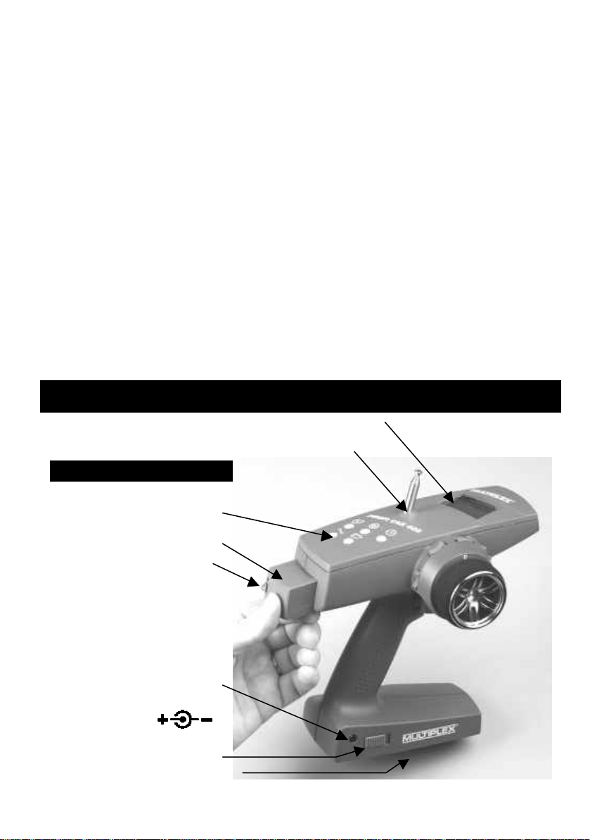
Use only
genuine
crystals
RF module
Charge socket
ON/OFF switch
Aerial (screw fitting)
Menu buttons
Screen
With thermal fuse!
dear fellow modeller,
we are delighted that you have decided to purchase a MULTIPLEX radio control system.
The „PROFI CAR“ is the first „pistol-grip“ transmitter designed and developed by MULTIPLEX.
Ergonomic efficiency and user-friendliness were our top priority during the development
process.
That’s not to say that we have neglected performance: the new system includes many
innovative and practical features, offering you facilities which until now have not been
available in systems of this class. They include:
v Interchangeable RF module, switchable to suit AM and FM receivers
v Up to 7 channels (steering, throttle/brake + 5 auxiliary channels)
v 2 steering servos and 2 brake servos (PROFI CAR 707 only)
v Separate throttle servo (PROFI CAR 707 only)
Of course, you don’t need to use these features; you can still operate the PROFI CAR as a
„completely normal“ set, i.e. with one steering servo and a second servo for throttle/brake.
We are confident that you will have many hours of pleasure with your PROFI CAR.
Yours the MULTIPLEX team
A quick look at the transmitter
Transmitter crystal
MULTIPLEX
maximum 600 mA
Transmitter battery in base
CAUTION:
2
Page 3

Contents
A quick look at the transmitter 2
Contents 3
Safety 5
System facilities 6
The transmitter controls in detail 7
The „instrument panel“ (screen) 8
The principle 9
Switching on for the first time 11
1.1. Charging the transmitter battery (maximum charge current 1 A) 11
1.2. Charging the receiver battery 11
1.3. Fitting the transmitter crystal 11
1.4. Adjusting the trigger loop 11
1.5. Testing the transmitter 12
2. Short and to the point 12
2.1. Selecting the vehicle TYPE 13
2.2. Setting the servo norm, direction of rotation, travels and centre 14
2.3. Adjusting STEERING L 15
2.4. Adjusting THROTTLE A 15
2.5. Adjusting BRAKE A 16
3. More about steering LL 17
3.1. Adjusting the steering servo („T“ menu) 17
3.2. Adjusting the steering trim („T“ menu) 19
3.3. Adjusting the steering CENTRE, accepting the trim setting 19
3.4. Setting the minimum steering TRAVEL 20
3.5. SLOW 21
3.6. EXPO 21
3.7. Auto Dual Rates for steering 21
3.7.1. Reduced Travel RT at full throttle 22
3.7.2. Auto Dual Rate delay 22
3.8. The second steering servo (PROFI CAR 707 only) 22
4. More about THROTTLE AA 23
4.1. 2-point throttle curve with EXPO 23
4.2. 5-point throttle curve 24
4.3. Automatic Start 25
4.3.1. Setting the „addition“ for Initial Throttle „IT+“ 25
4.3.2. Initiating the automatic start function using the trigger 26
4.3.3. Initiating the start function with the handle button or trigger 26
4.3.4. Terminating the automatic start phase 26
4.4. TC = traction control (nur PROFI CAR 707) 27
5. More about BRAKE 28
5.1. Two-point brake curve with EXPO 28
5.2. Trimming the Lock Point LP using rocker D 29
5.3. ABS = Advanced Braking System (PROFI CAR 707 only) 30
5.4. Braking with more than one servo (PROFI CAR 707 only) 31
3
Page 4

6. Timers and lap counters ºº 0000 33
6.1. Timer mode 33
6.2. Lap time memory 34
6.3. Setting the nominal time T-NOM 35
6.4. Setting the race duration (timer mode 3 only 35
6.4.1. Race duration by laps 35
6.4.2. Race duration by time 35
6.5. Checking the transmitter’s operating time 36
6.6. Erasing the timer ERASE 36
7. Model memories 11 37
7.1. Switching to a different model memory 37
7.2. Copying 37
7.3. Entering the model name 38
7.4. Erasing 38
7.5. Reverting to the PREVious state 38
8. Driving trucks 39
8.1. Selecting the model type 2+5 CH (truck) 40
8.2. Setting the control mode for the auxiliary channels 40
8.3. Adjusting travel and centre of the auxiliary channels 41
8.4. Truck steering and throttle/brake 41
9. The “toolbox” TT 41
9.1. Adjusting the trigger deadband („T “ menu, DEADB) 41
9.2. Switching between AM and FM („T “ menu, AM-FM) 42
9.3. Entering the owner’s name („T “ menu, NAME) 42
9.4. Selecting the display language („T “ menu, TEXT) 42
9.5. Setting the battery alarm threshold („T “ menu, ALARM) 42
10. Tips on installing the receiving system in the model 43
11. The system in use 44
11.1. Post Office Regulations for the U.K. 44
11.2. Range testing 44
11.3. Care of the transmitter 45
11.4. Maintenance 45
Specification, system characteristics 46
Menu summary for the PROFI CAR 403 and 707 47
4
Page 5

Safety
Radio-controlled models are not toys!
You can make a major contribution to safety when operating your models by acting
responsibly and handling your radio control system and model with due care.
v Check the electrical and mechanical connections in the model at regular
intervals.
v Check all moving parts regularly: they must be free to move, and must not
exhibit undue lost motion.
v Carry out regular range checks (see „Range testing“).
v When other drivers are present at the track, find out which channels are
already in use before you switch on.
v Before every run: extend the transmitter aerial to full length, and check that
it is in good condition and firmly seated.
v Check that you have selected the model memory corresponding to the
model you are running.
v Check all the working systems in your model before you start:
Do the servos rotate in the correct direction?
Are the travels correct?
v Are the transmitter and receiver battery adequately charged, and in well
maintained and roadworthy condition?
v Use only genuine MULTIPLEX crystals, batteries and accessories.
v If your receiving system includes components which are not covered by
these operating instructions, be sure to read the instructions supplied with
those items.
If you are in doubt on any point - don’t operate your model! Take your time, carefully
check the system again, and eliminate the fault. If you cannot solve the problem,
your local model shop or the MULTIPLEX customer service department will be
pleased to help you with advice and practical help.
Read and observe the notes in Chapter 11 on using the system!
!!
5
Page 6

System facilities
403 707
Model memories 6 12
Copy, reset, erase, enter model name
Steering
SLOW, separate for entering and exiting turns ü ü
EXPOnential steering curve (progressive / degressive) ü ü
Variable CENTRE and TRAVEL ü ü
Variable steering trim increment ü ü
Second steering servo - ü
Throttle
Automatic start system ü ü
EXPOnential throttle curve (progressive / degressive) ü ü
Separate THROTTLE / BRAKE servos - ü
5-point throttle curve ü ü
Traction-Control TC - ü
Brake
Variable engage point and lock point ü ü
EXPOnential brake curve (progressive / degressive ) ü ü
ABS (Advanced Braking System) - ü
Second brake servo (front / rear) - ü
Timer and lap counter
Operating time ü ü
Race duration by time / lap ü ü
Lap counter ü ü
Lap time memory 5 50
Mechanical features
Programmable trigger deadband
High-grip steering wheel lining
Ergonomic controls mounted on the handle
Angled screen for optimum legibility
Light weight
Signal transmission
FM or AM transmission, selectable for each model memory
Plug-in RF module (40/41 MHz and 72 MHz)
Externally accessible plug-in transmitter crystal
Power supply
600 mAh / 6-cell battery, approx. 3 hours operating time
Charge socket in transmitter base
6
Page 7
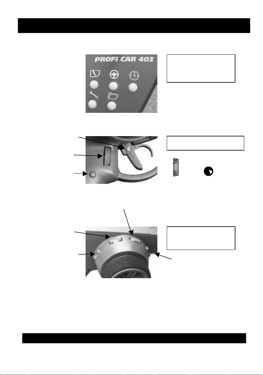
The transmitter controls in detail
HB
Handle Button
Digi Adjustor
Steering
Lock point
(throttle/brake servo)
„tuning centre“
Everything to hand
to the menus
adjustment screw
The three pictures below illustrate the essential controls.
The menu buttons
The trigger duster
Trigger loop
DA
The trim rockers
The „key“
DA HB
Initial throttle
rear brake
Repeat function
All trim rockers have an automatic repeat function when held pressed for longer than
about 1 second.
Special case – TRUCK:
If you wish to control a truck with your Profi Car, you have 5 auxiliary channels
available (see 8: Driving trucks). In this mode only the steering trim (rocker A) is
active; all the other rockers are used to control the auxiliary channels.
7
The
Switched channel or
lock point front brake
nd
(2
brake servo)
Page 8
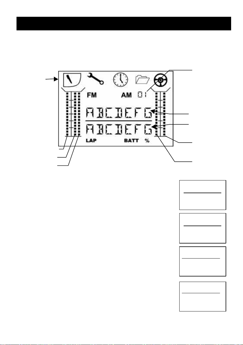
The „instrument panel“ (screen)
Steering travel
IT = Initial Throttle
Steering TRim
Brake 1
Brake 2
Text line 1
model memory
Text line 2
Menu
The picture below shows everything which the screen can display. What you actually
see at any one time depends on what you are doing: whether timers are active,
whether you are currently programming the transmitter, which type of vehicle you
have selected, etc.
A few examples are shown on this page.
Number of
Active
symbols
STV =
Operating display
Timer mode: OFF
If no timer function is active, the first text line displays the
model name you have entered. Text line 2 shows the
transmitter battery voltage.
STR =
BUGGY
7.4V
BATT
Timer Mode: LAP
The second text line shows the number of the lap on the lefthand side. To record the start and end of each lap you press the
handle button G.
Timer-Mode: L+T (Laps + Time memory)
In this mode the second text line shows the number of the lap
on the left (in our example 03) and the time for the current lap
on the right (in our example 28.3 sec).
Timer-Mode: L+T+E (Laps + Time memory + Race duration)
The first text line displays the total duration of the race (in our
example 2 min. 36.5 sec). The second text line shows the
number of laps and the time of the current lap, as in the
previous example.
BUGGY
03 7.4V
LAP BATT
BUGGY
03 28:3
LAP
2:36:5
03 28:3
LAP
8
Page 9

Special case: battery alarm with timer active
If one of the timer modes is active and the battery voltage falls to the alarm
threshold, the screen displays the current lap time and the battery voltage and BATT
warning, alternating at 2-second intervals.
When you are changing settings
When you are changing the transmitter settings, the first text
line shows the selected menu point (in our example: the
throttle curve). On the left of the second text line you see the
parameter which you have selected with the help of the handle
button (in our example full throttle). At bottom right the screen shows the current
value (in our example 87%) above the % symbol
G-CURV
FT 87
%
The principle
The five menu buttons on the PROFI CAR transmitter are the key to all set-up
processes. The button symbols tell you which menu points you can access with each
button.
Menu
button
A
L
U
T
F
Menu function
TRIGGER
Adjust everything which is concerned with the throttle, brake and
automatic start function;
on the PROFI CAR 707 it also includes TC (Traction Control) and ABS
STEERING
Adjust the steering to suit the track / vehicle / driver
Centre, travel, Dual Rates, Slow
TIMER
Select the timer mode (T-mode), set nominal time / lap data
Check and erase times
TOOLS
Select the vehicle type
Basic settings for servos, transmitter
MEMORY
Switch, copy, assign name, erase
9
Page 10
When you have found the menu point you want, you can continue by using the digiadjustor and the handle button.
HANDLE BUTTON (HB)
Select curve points
Confirm erasure, ...
DIGI-ADJUSTOR (DA)
Set values (travels, times, ...)
Select sub-menu points (if there is nothing to adjust)
Press any menu button (except the one you last used) to return to the operating
display.
When the operating display is on the screen (i.e. you have finished making
adjustments), the functions of the handle button and digit-adjustor are as follows:
HANDLE BUTTON (HB)
Operate timer functions
Lock brake (PROFI CAR 707 only)
DIGI-ADJUSTOR
Adjust steering travel
10
Page 11

Switching on for the first time
1.1. Charging the transmitter battery (maximum charge current 1 A)
First connect the charge lead (Order No. 12 5023) to the battery charger, then
connect the charge lead to the transmitter.
Charging the battery – important:
•• Automatic battery fuse
The battery of your PROFI CAR features an integral thermal fuse which protects the
battery from excessive currents if a short-circuit should occur.
This transmitter must be used with a genuine MULTIPLEX battery
fitted with this type of fuse!
If a short-circuit occurs and the fuse trips, the fuse element will reset itself about
!!
1 minute after the fault is corrected, and the unit will then work again normally.
•• Charging the battery - note:
If you charge at the standard (slow) rate, no restrictions apply.
If you fast-charge the battery using a charger with automatic termination, the charge
current must not exceed 600 mA. Exceeding this rate may cause the thermal fuse to
trip, and the charge process will be interrupted prematurely.
1.2. Charging the receiver battery
Observe the manufacturer’s notes on charging, as printed on the battery.
Do not exceed the stated charge currents!
1.3. Fitting the transmitter crystal
Transmitter crystals have a blue sleeve and bear the code letter „S“ before the
channel number. Ensure that the transmitter and receiver crystals are on the same
channel.
Plug the transmitter crystal into the RF module (see picture on page 2).
Please be very careful when handling crystals:
v Don’t drop them
v Don’t force a crystal into its socket
v Protect them from vibration in use and in storage
1.4. Adjusting the trigger loop
You can adjust the trigger loop to suit your finger size by loosening the screw in the
trigger.
CAUTION: don’t over-tighten the screw after making the adjustment, as this could
loosen the nut pressed into the other side!
11
Page 12

1.5. Testing the transmitter
Now you can switch on the transmitter and a receiving system and generally try
things out. All you need is a receiver, two servos connected to channels 1 and 2, and
a battery. If you prefer to use an existing model car, make sure that the steering servo
is connected to channel 1 and the throttle/brake servo to channel 2.
Now you can continue with Section 2.
2. Short and to the point
In this section you will discover the five simple steps required to get your first model
car „up to speed“. This is the procedure in brief:
2.1 Select the vehicle type
Adjust the transmitter to suit the model (number of channels, ...)
2.2 Set the servo norm, centre and travels
Adjust the servos to suit the mechanical system in your model
(the „S-NORM“ menu point includes direction of rotation)
2.3 Adjust the steering set up to suit your
2.4 Adjust the throttle personal preferences
2.5 Adjust the brake and the track characteristics
12
Page 13

2.1. Selecting the vehicle TYPE
Selecting the vehicle TYPE determines the channels which are to be used to control
your model.
The PROFI CAR 403 offers the following options.
TYPE Steering Throttle + Brake Special features
STANDSTAND
e.g.
electric car
2+1 CH2+1 CH
Servo
1
Servo
2
GP car
2+5 CH2+5 CH
Truck
The PROFI CAR 707 also includes:
v ABS Advanced Braking System
v TC Traction Control
v and two new vehicle types:
TYPE Steering Throttle/brake 2nd brake Special features
4 CH4 CH
TYPE Steering Throttle Brake Special features
5 CH5 CH
Profi
Servo
1 + 4
Servo
1 + 5
Servo
2
Servo 2 Servo
3 + 4
EXPO on THROTTLE
Switched channel for servo 3
5-point curve for THROTTLE
Switched channel for servo 3
Switched channels for servo 3 to 7
EXPO on THROTTLE
Servo
3
2 steering and 2 brake servos
5-point curve on THROTTLE
no auxiliary channel
2nd brake servo on channel 3
5-point curve on THROTTLE
no auxiliary channel
For your first attempts we recommend that you select the vehicle type STAND
(standard) or 2+1 CH.
13
Page 14
This is the procedure:
TYPETYPE
Search for menu
point
Select type
Confirm and
terminate
STAND
2+1CH
4CH
5CH
2+5CH
X Confirm. Beep
2.2. Setting the servo norm,
direction of rotation, travels and centre
If you select STAND or 2+1 CH as the vehicle type, all you need to do is set up the
servos: servo 1 „STEERING“ and servo 2 „THROTTLE/BRAKE“.
SS --NORMNORM
Search for menu point
Select servo
Select norm / direction,
check by moving trigger or
steering wheel
S-NORM
2: MR
UN UNI normal
UR UNI reverse
MN MPX normal
MR MPX reverse
SS --TRAVTRAV
L A
Search for menu point
Select servo
Example:
Servo 2, centre –12%
Right, centre, left
select by turning steering
wheel
(for servo 2 use trigger)
then set using digi-adjustor
S-TRAV
2: • -12
%
ŒŒ right 0 – 100 %
•• centre +/- 25 %
LL left 0 – 100 %
§ Press any button (except T ) to return to the operating display.
14
Page 15

2.3. Adjusting STEERING LL
Steering settings:
CECENTRNTR
TRAVTRAV
DUALDUAL
SLOWSLOW
EXPOEXPO
§ Use the L button to search for the menu point SLOW, EXPO, CENTR or
§ Set the value you want using the digi-adjustor
§ Press any button (except L ) to return to the operating display.
Servo centre (straight ahead) - 50% to + 50%
Minimum steering travel,
if set using digi-adjustor
Auto Dual Rates
DE = delay 0 to 5
RT = reduced travel
Retards steering movements
Enter/exit turn separately
Exponential steering curve
TRAV
30% to 100%
Switch off with „DE = 0“
50% to 100%
0.0 sec to 1.0 sec
+100% = soft
-100% = hard
2.4. Adjusting THROTTLE AA
You must set either a 2-point or 5-point throttle curve, depending on the vehicle
type you have selected.
For the STANDard and TRUCK vehicle types:
2 point throttle curve
LL
IT
FT
EXP
Idle 0% to 100%
Initial throttle =
initial throttle value when trigger
leaves deadband
Full Throttle 0% to 100%
Exponential throttle curve
with EXPO
0% to 100%
+100% = soft start
-100% = hard start
For the vehicle types „2+1 CH“, „4 CH“ and „5 CH“
5-point throttle curve
ID
IT
2T
3T
4T
FT
Idle 0% to 50 % 15%
Initial throttle = initial throttle value
when trigger leaves deadband
Points on the throttle curve 0% to 100%
Full throttle 0% to 100% 100%
15
Range Default setting
0% to 100% 30%
45%
60%
75%
Page 16

This is the procedure for setting the separate points on the throttle curve:
§ Search for the menu point T-CURV (throttle curve) using the A button
§ Search for the point to be adjusted using the handle button G
§ Set the value using the digi-adjustor
§ Press any button (except A ) to return to the operating display
2.5. Adjusting BRAKE A A
The settings for the brake are the same for all vehicle types. EXPO is also available in
all vehicle types.
Point to be adjusted Range
EPEP
LPLP
EXPEXP
IF you set EXPO to +100% the brake is applied „gently“; at -100% the brake is applied
hard. Setting EXPO to 0% switches exponential off.
Engage Point =
Brake setting when trigger leaves deadband
Lock point 0% to 100%
Exponential brake curve ±100%
§ Search for the menu point BREMS1 (brake curve for the throttle/brake
servo) using the AA button.
§ Search for the point to be adjusted (EP/LP/EXP)
using the handle button G.
§ Set the value you want using the digi-adjustor
§ Press any button (except A ) to return to the operating display
0% to 100%
üü That’s all you need to do. It should now be possible to run your car
and control it properly.
16
Page 17

3. More about steering LL
The PROFI CAR provides the following facilities for adjusting the steering:
• Servo centre and servo travel {3.1} (T menu, menu point „S-TRAV“, servo 1)
These facilities allow you to adjust the servo to suit the mechanical set-up in your
model, and at the same time set the maximum steering travel and centre setting
for accurate straight running.
• Steering CENTRE {3.3} (L menu, menu point „CENTRE“)
In this part of the menu you can correct the car’s straight running. The steering
trim also affects this value, and you can „automatically“ accept the trim value as
the centre in this menu point.
• Steering TRAVEL {3.4} (L menu, menu point „TRAVEL“)
At this point you can enter a value for the minimum steering travel which you
can set using the digi-adjustor when the car is running. This avoids the danger of
inadvertently setting such a low value that you suddenly run out of steering
travel when you most need it. 30% is the minimum value.
• SLOW {3.5} (L menu, menu point „SLOW“)
You can adjust the transit speed of the steering servo separately for entering
turns „••“ and for exiting turns „••“.
• EXPO {3.6} (L menu, menu point „EXPO“)
You may like to adjust the steering so that response to the wheel is more or less
sensitive than normal around the centre setting. This is achieved by setting a
value for EXPOnential.
• Auto Dual Rates (L menu, menu point „DUAL“)
Dual Rates means reduced servo travel, and Auto Dual Rates means that the
travel of the steering servo is reduced automatically when the throttle setting is
increased. At full throttle steering travel is small, at idle steering travel is large.
At the DUAL menu point you can
1. set the value at which reduced steering travel (RT) takes effect
2. set the delay (DE) which applies to the automatic travel reduction
• Increment size for steering travel and trim setting {3.2}
(T menu, menu point „STEP“)
Each movement of trim rocker A (steering centre) and of the digi-adjustor
(steering travel) produces one increment of change; the step size can be set to
any value between fine (1% increments) and coarse (10% increments).
3.1. Adjusting the steering servo („TT“ menu)
You must adjust the servo to suit the mechanical set-up in your model before you
alter the steering settings in the L menu. In more detail this means: setting the
direction of rotation / and pulse width (norm) of the servo, and setting appropriate
values for left ( ), straight ( ) and right.
17
Page 18

The diagram on the right
shows an example of the
settings you can change in
the „S-TRAV“ menu. The
stated angles (0° / 45°) show
the servo’s maximum physical travel. The adjustment
points „LL “ and „ŒŒ “ indicate
the maximum travel of the
steering servo which the
user has set. To adjust either
of these points you have to
turn the steering wheel in
the corresponding direction.
When the servo is at the „•• “ point you can adjust the servo setting for „straight“.
In the „S-NORM“ menu point
you can also set the direction of rotation for the servo, and choose between the
MULTIPLEX and UNIVERSAL signal formats. MULTIPLEX norm means that the signal
length (pulse width) for the centre setting is 1.6 ms, and the signal range is
+/- 0.55 ms. The UNIVERSAL norm means that the servos operate on 1.5 ms +/-0.5 ms.
This is the procedure:
SS --NORMNORM
Search for menu
point
SS --TRAVTRAV
L
Select servo 1
Select norm and
direction of
rotation
Search for menu
Point
Select servo 1
Select right, centre,
left by rotating
steering wheel,
then set using digiadjustor
S-NORM
1: MR
UN UNI normal
UR UNI reverse
MN MPX normal
MR MPX reverse
S-TRAV
1: •- 3
%
ŒŒ right 0 – 100 %
• • centre +/- 25 %
L L left 0 – 100 %
18
Page 19

3.2. Adjusting the steering trim („TT“ menu)
The steering is trimmed using the trim rocker A. You
can easily find this rocker „blind“ because its shape
and fluted surface differentiate it from the other
rockers
You can use the steering trim to adjust the centre of
the steering servo by 7 increments in each direction.
Each step offsets the centre by at least 1% (fine) and
at most 10% (coarse). You can select the size of the
trim increments in the menu point STEP of the „*“
menu. The default setting is 2%.
The screen shows the current trim settings in the form of a vertical bar.
STEP
STR 2
%
1 – 10%
T
STEPSTEP
Serrate for menu
point
Search for
parameter
STR =Steering TRim
Set size of
trim increment
3.3. Adjusting the steering CENTRE, accepting the trim setting
In this menu point you can do two things:
v Set the steering servo centre within the range -50% and +50%, and
v accept the trim setting
CENTRE
- 8
%
The current trim value is added to
the centre, and then reset to zero.
L
CENTRECENTRE
> 3 sec
Search for menu
point
Set the centre
(e.g.: -8%)
Accept the trim
setting as centre
19
Page 20

Accepting the trim is a practical and useful facility. For example, if
you suffer a „slight crash“ which knocks the basic setting out, you
can quickly and simply regain the full trim range.
The diagram on the right shows the screen display before and after
accepting the trim setting. On the left the centre is offset by 3 steps,
while on the right the setting has been accepted, and the trim
display is back to centre. If you have selected, say, 3% as the trim
increment when trimming the steering centre SC, this means that
„CENTRE“ is offset by 9% (3 increments of 3%).
3.4. Setting the minimum steering TRAVEL
During a race you can alter the steering travel with the digi-adjustor, so that it is
always accurately matched to the track you are using.
Please note: this only works if the screen shows the operating display!
The actual steering travel you have set is shown by the bar on the far right of
the screen. In our example 2/3 of the maximum possible range is available
between minimum and maximum.
To avoid the possibility of reducing steering travel to zero, you can at this
point set a value for the extent to which steering travel can be reduced using
the digi-adjustor, i.e. you can fix the minimum steering travel. The
adjustment range is 30% to 100%.
L
TRAVELTRAVEL
Search for
menu point
Set travel
(e.g.: 72%)
TRAVEL
72
%
Range: 30% to 100%
Increment: 1% to 10%%
Default setting: 44% travel
2% increment
' TIP !
Set the maximum steering travel by adjusting the basic mechanical set-up of the
steering servo (see 3.1).
Make adjustments in the „T“ menu, menu point „S-TRAVEL“, servo 1.
' TIP !
The rate at which the digi-adjustor affects the steering travel
increment size.
Make adjustments in the „T“ menu, menu point „STEP“, „STV“
20
is determined by the
Page 21

3.5. SLOW
SLOW retards the movement of the steering servo, and reduces the tendency for the
steering system to oscillate when the load on the wheels is light, and the steering
movements are rapid. The delay time is variable separately for „entering the turn“
and „exiting the turn“ (returning to straight running), in both cases within the range
0.1 to 1.0 sec.
If you select the vehicle TYPE „5 CH“, with two steering servos, SLOW affects both
servos simultaneously, as you would expect.
L
SLOWSLOW
Search for menu
point
e.g.: 0,7 sec for
“exit curve”
Search for
parameter
Set time Range: 0,0 to 1,0 sec
SLOW
•• 0.7
•••• enter curve
•••• exit curve
Increment: 0,1 sec
Default setting: 0,0 sec
3.6. EXPO
EXPO affects the steering response of your model car. If you set a positive value (e.g.
+50%), the steering travel around the centre is reduced, making it easier to steer the
model on straight stretches at high speeds.
A negative EXPO value produces the opposite effect, making the steering response
more direct around centre.
L
EXPOEXPO
Search for menu
point
e.g.: +70%
Adjust EXPO Range: -100% to 100%
EXPO
70
%
Increment: 5%
Default setting: 0%
3.7. Auto Dual Rates for steering
The effect of Auto Dual Rates is to produce an automatic reduction in steering travel
when you open the throttle (see 2.7.1.).
It is also possible to program a delay in the speed with which the automatic travel
reduction is applied, to ensure that short bursts of throttle don’t produce an
unwanted reduction in steering response (see 2.7.2.).
This function can be disabled by setting the delay value DE to „0“.
21
Page 22

3.7.1. Reduced Travel RT at full throttle
§ Search for the menu point „DUAL“ using the L
button
§ Search for RT with the handle button G
§ Use the digi-adjustor to set the value you want within the range 50% to
100% (example: 57%).
Finally you must set the delay DE (see next section) to a value within the range 1 to 5.
3.7.2. Auto Dual Rate delay
The delay can be set to any of 5 values. Set DE = 0 to switch the
function off.
§ Search for the menu point „DUAL“ with the L button
§ Search for DE using the handle button G
§ The value can now be set within the range 0 and 5 using the digi-adjustor
(example: 2).
DUAL
RT 57
%
DUAL
DE 2
' TIP !
Before you go onto the track, check the effect of your Auto Dual Rates settings with
the model in the pits (set the steering to full travel, then open the throttle).
3.8. The second steering servo (PROFI CAR 707 only)
At present two steering servos are generally used in models where one servo alone
cannot produce the power required. The two servos are mechanically connected,
and must be synchronised perfectly to avoid them counteracting each other.
You can use two steering servos (on channels 1 and 5) if you select the vehicle type
„5 CH“ on the PROFI CAR 707 transmitter.
IMPORTANT: all settings in the „LL“ menu apply to both servos !
!!
The two servos should be adjusted to suit the model’s mechanical set-up; this is done
in the menu points „S-NORM“ and „S-TRAV“ of the „T“ menu. You can compensate
for any differences between the two servos by making adjustments in the menu
point „S-TRAV“.
' TIP !
If you wish to alter the servo norm or travel, disconnect the mechanical link between
the two servos first to avoid the danger of placing an unnecessary strain on the
servos.
22
Page 23

4. More about THROTTLE AA
The PROFI CAR also has plenty of interesting facilities to offer for throttle:
v 2-point throttle curve with EXPO, or 5-point throttle curve
v Automatic Start
v TC (traction control) PROFI CAR 707 only!
v Separate throttle servo PROFI CAR 707 only!
To help you understand:
The diagram on the right shows
which servo settings are assigned
to the individual points on the
throttle-brake curve.
Between the points Initial Throttle
IT and Full Throttle FT the setting of
the throttle servo is proportional to
the position of the trigger.
At the idle setting (ID) the servo
does not move, provided that the
trigger stays within the deadband {variable: see 9.1}. As soon as the throttle trigger
moves into the working range, the throttle servo jumps to the Initial Throttle position
IT.
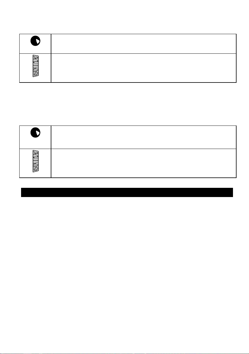
4.1. 2-point throttle curve with EXPO
The two-point throttle curve is generally adequate for electric-powered model cars.
With the help of the EXPO facility you can easily set up a throttle response curve
which gives you just the feeling of control you prefer.
Use the menu button A to locate the throttle curve, and the handle button
select the individual points on the curve. The advantage of this system is that you
don’t actually have to apply full throttle in order to adjust the full throttle point.
G
to
The diagram on the right shows the
correlation between the trigger move-met
and the servo travel in graphic form.
The area with the grey background is the
deadband. As long as the trigger stays within
this range, the throttle/brake servo stays at
the idle setting IDL.
Between the two points Initial Throttle IT and
Full Throttle FT the throttle curve is linear assuming that you have set EXPO to 0%. The
dotted lines show how EXPO affects the throttle curve
23
with EXPO
Page 24

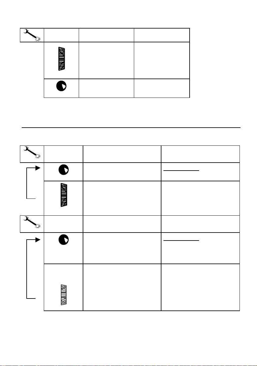
This is the procedure:
A
GG --CURVCURV
Search for menu
point
Search for point on
throttle curve
e.g.: Initial Throttle
35%
Set the value
4.2. 5-point throttle curve
The main advantage of the 5-point
throttle curve is to set up a
response curve which compensates
for the characteristics of the
carburettor of an internal combustion engine. Between the two
points Initial Throttle IT and Full
Throttle FT there are three further
points which you can set to the
values you find best.
The settings are adjusted using the
same procedure as described for
the 2-point throttle curve in the
preceding section 4.1.
G-CURV
IT 35
%
ID Idle
IT Initial Throttle
FT Full Throttle
EXP EXPO
The brake curve is the same for all
vehicle types.
24
Page 25

4.3. Automatic Start
The automatic start facility triggers a series of special functions once only at the start
of the race. The automatic start function must first be activated in the * menu. It can
be initiated (triggered) in two ways, depending on the vehicle TYPE you have
selected: either by the action of opening the throttle for the first time, or by pressing
the handle button at the same time.
When you activate the automatic start function, the following happens:
• All vehicle types: the timer and lap counter are set to starting values.
• Vehicle type STAND (standard) and 2+5 CH:
The throttle curve is altered for the start
phase. You will find the start value as „IT+“ in
the menu point „T-CURV“. The value which
you set here increases (or decreases if you
prefer) the „normal“ initial throttle setting.
However, this change only applies until the
initial start phase is finished (see below).
When the automatic start function is
triggered, the throttle response follows curve
Œ. If you stay within the working range of the automatic start function, with your
finger on the trigger, the throttle moves to a fixed setting. This setting can be
fine-tuned to suit your vehicle exactly. When you move the trigger into the
deadband, or above the Initial Throttle setting as increased using the „IT+“ value,
the throttle response reverts to curve •.
• Vehicle type 2+1 CH, 4 CH and 5 CH:
In the vehicle types which feature a 5-point
throttle curve the „addition to Initial
Throttle“ is effective over the first four
points of the throttle curve, as shown in
curve ΠOn this curve the automatic start
function continues in effect until the
throttle trigger exceeds point 4 on the
throttle curve (i.e. in the direction of full
throttle), or if the trigger is moved into the
deadband. From this moment the throttle
response reverts to curve •.
4.3.1. Setting the „addition“ for Initial Throttle „IT+“
' TIP ! The setting for „IT+“ can only be changed when the
automatic start function is active.
§ Search for the menu point „START“ using the A button.
§ Switch the function „ON“ using the digi-adjustor.
You will now see the TRIGGER symbol flashing at the top
left of the screen.
25
START
ON
Page 26

§ Proceed to „T-CURV“ using the A button.
%
§ Search for the „IT+“ value using the handle button G.
§ Set the value you want using the digi-adjustor.
In the example shown on the right the set value is 16%.
If you move back to the operating display by pressing any menu button (except A ),
the top line of the screen will alternate between the model name and „START“.
G-CURV
IT+ 16
' TIP !
The automatic start function can only be triggered when the operating display is on
the screen
4.3.2. Initiating the automatic start function using the trigger
This works with all vehicle types. When the trigger is moved from the deadband in
the direction of full throttle for the first time, the following things happen:
§ The timer and lap counter start running, and are shown on the screen (varies
according to the selected timer mode).
§ The set „addition“ for initial throttle comes into force (see 4.3.1.).
Once the automatic start is initiated, only the model name appears on the screen.
4.3.3. Initiating the automatic start function with the handle button or trigger
If your model is equipped with separate servos for throttle and brake (vehicle types
„3+1 CH“ and „5 CH“), there are two methods of starting:
§ Lock the brake by pressing the handle button G. Now you can blip the
throttle, and the car will not roll away.
§ When you release the handle button G the car will start - provided that the
trigger is not in the deadband.
§ If the trigger is in the deadband (idle) you can release the brake (handle
button). You can then start the car by squeezing the trigger, as described
below.
4.3.4. Terminating the automatic start phase
When the start phase ends, the program switches off the addition to the initial
throttle setting „IT+“, and the throttle response reverse to the „normal“ curve (2 or 5
points)..
The correlation between these values is illustrated in the diagrams in Section 4.3,
termed the „automatic start function working range“.
§ If a 2-point throttle curve is in use, the start phase ends when you move the
trigger to the deadband (idle), or when the throttle trigger exceeds the value
determined by Initial Throttle and IT+.
§ If you have set a 5-point throttle curve, the start phase ends when you move
the trigger into the deadband, or when the throttle trigger exceeds the
fourth point on the throttle curve „4T“.
26
Page 27

4.4. TC = traction control (PROFI CAR 707 only)
Traction Control is a variant of the SLOW function applied to THROTTLE, in this case
only working when you open the throttle. When you close the throttle, the servo (or
speed controller) responds normally, i.e. without any delay.
Traction Control prevents the wheels spinning during acceleration on a smooth
track. In the case of electric cars TC reduces current drain, because the motor is
controlled more „gently“.
There are two parameters to be set for Traction Control:
1. T = Time, between 0 and 2.0 sec
Time factor for retarding the throttle servo
2. ACC = Acceleration, between 0 and 10
works in a similar way to EXPO
The diagram on the right shows
how you can imagine the effect of
the TC function.
We will assume that you want the
throttle to move from the ACTUAL
position to the NOMINAL position
(see labels on graph), because you
have moved the trigger slightly in
the direction of full throttle.
Without TC this change takes place
at a rate determined by the servo’s
transit speed (see curve 1).
If you set the parameter T (= time) for Traction Control to the maximum value 2.0, the
movement of the servo is retarded, but the line of the graph remains linear (curve 2).
If we now add a little ACC to the mix, we obtain the desired line as shown by curve 3.
Initially the throttle opens slowly (thereby preventing the wheels spinning), but the
rate of opening then increases steadily. This set-up shortens the total duration of the
servo’s movement, but without losing the advantage of the „gentle“ start-up.
This is the procedure:
§ Search for the menu point TC using the A button.
§ Select T or ACC using the handle button G.
§ Set the value you want using the digi-adjustor.
Press any menu button (except A ) to return to the operating display.
27
Page 28

5. More about BRAKE
The PROFI CAR offers the following brake functions:
v 2-point brake curve with EXPO {see 5.1}
v ABS Advanced Braking System (PROFI CAR 707 only)
v Second brake servo (PROFI CAR 707 only)
To help you understand:
The diagram on the right shows the
servo positions which correspond
to the individual points on the
throttle-brake curve.
Between the engage point EP and
the locking point LP the servo
responds proportionally to the
movement of the trigger.
At the idle position IDL the servo
does not move, as long as the
trigger stays within the deadband {variable: see 9.1}. As soon as the trigger is moved
into the „brake“ working range, the servo jumps to the Engage Point EP.
5.1. Two-point brake curve with EXPO
Use the menu button A to locate the brake curve. The individual points on the
curve are selected using the handle button
The diagram on the right illustrates the
correlation between the trigger movement
and the servo travel in graphic form.
The area with the grey background is the
deadband. If the trigger stays within this
range, the throttle/brake servo stays at the
idle position IDL.
Between the engage point EP and the
locking point LP the brake curve is linear assuming that you have set EXPO to 0%. The dotted lines show how EXPO alters the
brake curve.
28
Page 29

This is the procedure:
BRAKE1
EP 27
%
IDL Idle -50% to +50%
A
BRABRAKE1KE1
Search for menu
point
Search for point on
brake curve
Example:
Engage point 27%
Set value
EP Engage point OFF or
1 – 100%
LP Lock Pint 0 – 100%
EXP EXPO ± 100%
If you are using a combined throttle/brake servo (all vehicle types except „5 CH“),
!!
the idle point „IDL“ exists on the throttle curve as well as the brake curve
5.2. Trimming the Lock Point LP using rocker D
The lock point of the brake normally changes
during a race, so it is helpful to be able to
compensate for that change. This is done by means
of trim rocker D. Rocker D affects the lock point of
the THROTTLE/BRAKE servo (servo 2) or servo 3 (first
brake servo) of the vehicle types 3+1 CH and 5 CH.
The brake trim allows you to adjust the lock point by
7 increments in each direction. Each increment
offsets the lock point by at least 1% (fine) and at
most 10% (coarse). You can select the size of the
trim increments in the menu point „STEP“ of the „T“ menu.
The default setting is 2%.
29
Page 30

The current trim setting is indicated on the screen by a vertical bar. In the example on
the right the lock point of the first brake servo has been offset in the direction of
„stronger braking effect“ by 3 trim increments.
STEP
LP 78
%
1 – 10%
T
STEPSTEP
Search for menu
point
Select parameter
LP = Lock Point
Set size of
trim increment
' TIP !
If you have a second brake servo (vehicle type „5 CH“), the increment size you select
applies to both trim rockers (B and D).
5.3. ABS = Advanced Braking System (PROFI CAR 707 only)
In the model car racing field ABS corresponds to an intermittent brake: instead of
being applied constantly, the brake is applied then released again continually at
short intervals. This method of braking keeps the vehicle on line better, making it
easier to steer under heavy braking.
In the PROFI CAR the ABS function is activated automatically when the steering
deflection exceeds a variable threshold (TH = threshold point).
' TIP !
If you set the threshold point to 0%, ABS is effective all the time.
This allows you to try out its effect on a straight stretch of track.
A A
ABSABS
Search for menu
point
Select parameter
Set value Effect
ABS
AB 3
%
TH threshold point 0 – 50%
EF Effect 0 – 4
0 OFF
1 soft
...
4 hard
30
Page 31

5.4. Braking with more than one servo (PROFI CAR 707 only)
If you have chosen the „4 CH“ or „5 CH“ vehicle type, you can use two brake servos;
this allows you to control the brakes for the front and rear axles separately.
In vehicle type „4 CH“ you have:
v servo 2 for throttle/brake (rear wheels)
v servo 3 for the second brake (front wheels)
In vehicle type „5 CH“ you have:
v servo 2 for throttle alone
v servo 3 for the first brake (rear wheels)
v servo 4 for the second brake (front wheels)
When you select one of these vehicle types, you can adjust the brakes using the „A “
menu, where you will find the menu points „BRAKE1“ and „BRAKE2“, both of which
feature the same parameters (idle ID, engage point EP, lock point LP and EXPO).
Setting of the brake servos when you open the throttle:
!!
If a combined throttle/brake servo is connected to channel 2, the servo responds to
the throttle and brake commands, but if there is a separate brake servo (servo 3 or 4),
it only moves when the trigger is moved into the brake range. As soon as you open
the throttle, these servos jump to a fixed position which we can term „brake fully off“.
The servo position for „brake fully off“ can be set for servos 3 and 4 in the menu point
„S-TRAV“ within the „T“ menu. To be able to change this value you must hold the
trigger in the throttle range. You will see the symbol „L“ on the screen.
' TIP !
Brake engaged when the trigger is in the deadband (finger relaxed):
If you want the brakes in
your model car to
operate in this way, you
must set the engage
point to 0. Instead of the
0 you will then see „OFF“
on the screen. If the
brake servo is programmed in this way it will
behave as shown in the
diagram at far right. The
servo no longer jumps to
the engage point when
the trigger is moved out of the deadband.
31
Page 32

The lock points for the two brake servos can be
B
D
trimmed using the rockers B and D (see picture). We
have selected these particular rockers so that you
can easily remember the assignment:
front rocker è front brake
rear rocker è rear brake
This is the procedure:
BRAKE2
LP 82
%
IDL Idle -50% to +50%
A
BRAKE1BRAKE1
BRAKE2BRAKE2
Search for menu
point
Select the brake
curve
Example:
Lock point 82%
Set value
EP Engage Point
0 (OFF) to 100%
LP Lock Point 0 to 100%
EXP EXPO ± 100%
Press any menu button (except A ) to return to the operating display.
32
Page 33

6. Timers and lap counters ºº 0000
The PROFI CAR (403 and 707) offers the following facilities for timing and lap
counting:
v Operating time
This timer can be reset to zero in the „T “ menu. It is used to record the
operating time of the transmitter battery or the transmitter itself. This timer
always runs when the transmitter is switched on.
v Nominal lap time
For practising you can set a „nominal time“ (target time) for a single lap. The
transmitter gives an audible signal to let you know whether you were faster
or slower than the set time.
v Race duration
You can enter the race duration in the form of a number of laps or a set time.
The transmitter alerts you to the start of the last lap with an audible signal.
v Memory for 50 lap times
Once you have selected the appropriate operating mode (timer mode), you
can „stop“ lap times with the handle button G . The transmitter’s memory
can store up to 50 lap times, and the times are retained even when you
switch off the transmitter or replace the battery.
v Total race time
A special memory (on-screen symbol „–“) is available as a stopwatch for the
entire race.
You can select the following menu points using the U button:
TT --MODEMODE
OPTIMEOPTIME
ERASEERASE
TIMESTIMES
TT --NOMNOM
DURADURA
Timer mode 6.1
Check transmitter operating time 6.5
Erase lap counter, time memory, nominal time,
race duration (time and lap count) and operating time
Check lap time memory 6.2
Enter the nominal time for a lap 6.3
Enter the race duration as a time or No. of laps 6.4
6.6
6.1. Timer mode
There are three different modes of operation for the timer. The fourth possible mode
is to switch off the timer functions entirely (T-MODE: OFF).
Mode Effect
OFFOFF
LAPSLAPS
L+TL+T
L+T+DL+T+D
All timer functions switched off
Lap counter active
Lap counter + lap time memory active
Lap counter + lap times + race duration
33
Page 34

The timer mode can be set differently for each model memory.
This is the procedure:
§ Search for the menu point T-MODE using º
§ Select the mode using the digi-adjustor
Press any menu button (except º ) to return to the operating display.
6.2. Lap time memory
The transmitter can store up to 50 lap times and call them up again. When a new lap
is completed, all the lap times already recorded are shifted back by one place. When
the lap memory is full, the oldest value is always erased to make room for the new
one.
§ The time memory „–“ contains the overall time of the last race.
§ The time memory 01 contains the last recorded lap time.
This memory stores all lap times, regardless of the model you are using for that race.
This could mean that you lose track of different races when leafing through the
times, so the screen always shows the number of the model memory associated with
the recorded time.
ºº
02
TIMES
Time memory No. 7 Lap time in sec.
End of lap = start of new lap:
A short press on the handle button triggers four functions:
§ the lap counter LAP is increased by 1,
§ the timing of the current lap halts,
§ the measured lap time is stored in the transmitter’s memory, and
§ the timing of the next lap starts.
End of race:
If you hold the handle button G pressed in for longer than 2 seconds, a long beep
sounds to signal that the transmitter has stopped timing and counting laps.
Calling up recorded lap times:
§ Search for the menu point TIMES using the º button.
§ Leaf through the timer memory 01 to 50 using the digi-adjustor.
„-“is the fifty-first memory containing the total race time.
Press any menu button (except º ) to return to the operating display.
07 17:9
LAP
Model used for the lap
time displayed
34
Page 35

6.3. Setting the nominal time T-NOM
You can enter a nominal time T-NOM for a lap, so that you can check your practice
times against the set value. The maximum variable time is 1 min. 59.9 sec.
When you finish a lap (short press on the handle button G), an audible signal
informs you of the result:
X 1 short beep = lap time equal to or lower than nominal lap
X X X 3 short beeps = lap time longer than nominal lap
This is the procedure for setting the nominal time:
§ Search for the menu point T-NOM using the º button
§ Alter the flashing number with the digi-adjustor
§ Press the handle button G to move to the next digit
Press any menu button (except º ) to return to the operating display.
6.4. Setting the race duration (timer mode 3 only
For practice purposes you can set a race duration, determined either by a particular
number of laps or by a particular time.
6.4.1. Race duration by laps
You can enter the number of laps to be run (max. 99) in the
menu point DURA, LAP. In the example on the right the set
number of laps is 17.
The start of the race is initiated by the automatic start function, or by pressing the
handle button. At the end of each lap you have to press the handle button, to signal
to the transmitter that a lap is finished, that lap timing should begin again, and that
the lap time should be stored.
The transmitter produces the following audible signals:
X X X 3 short beeps at the start of the last lap
DURA
LAP 17
XX 1 longer beep at the end of the race
6.4.2. Race duration by time
You can enter the race duration (max. 1 hour 59 min.) in the
menu point DURA, T. In the example on the right the set time is
12 minutes.
The start of the race is initiated by the automatic start function or by pressing the
handle button. At the end of each lap you have to press the handle button to signal
to the transmitter that a lap is finished, that lap timing should begin again, and that
the lap time should be stored.
The transmitter produces the following audible signals:
X X X 3 short beeps at the start of the last round
DURA
T 0:12
35
Page 36

The transmitter can only produce this signal if your car has completed at least six
laps. The transmitter computes the average time for the last six laps, then calculates
whether a further full lap can be completed in the time remaining to the end of the
race. If not, the 3-beep signal is given. When you next press the handle button the
transmitter stops the timing process.
This is the procedure:
§ Search for the menu point DURA using the º button
§ Select T (time) or LAP (laps) with the handle button G
§ Alter the value using the digi-adjustor
Press any menu button (except º ) to return to the operating display.
6.5. Checking the transmitter’s operating time
This menu point can only be used to check the operating time.
To erase the data you must proceed to the ERASE menu point.
§ Select the menu point OPER using the º button
The time is displayed in hours and minutes.
Press any menu button (except º ) to return to the operating display.
OPTIME
6:17
6.6. Erasing the timer ERASE
This menu point can be used to erase the following times (or settings):
Item this value is erased (reset to 0):
L+TL+T
NOMNOM
DURADURA
OPTIMEOPTIME
The lap counter and all time memories
Set nominal lap time
Time and lap count for the race duration
Operating time
This is the procedure:
§ Search for the menu point ERASE using the º button
§ M Use the digi-adjustor to select the item you wish to erase
§ Hold the handle button G pressed in for longer than 3 sec to erase the data
Press any menu button (except º ) to return to the operating display.
36
Page 37

7. Model memories 11
The model memories are used to store all the settings which you have entered for a
particular vehicle. These settings include:
v Modulation (FM/AM)
v Servo direction, signal format, centre, travels
v Settings for throttle, brake and steering
v Timer settings
v Trim settings
The information in the active model memory is updated when you switch off the
transmitter or switch to a different memory.
v PROFI CAR 403 6 model memories
v PROFI CAR 707 12 model memories
The memory space available is generous, and the spare memories can be exploited
to experiment with copying model data, or trying out different settings for a
particular race track.
7.1. Switching to a different model memory
§ Search for the menu point GO TO using the 1 button
§ Select the target memory with the digi-adjustor
The screen shows the name, memory number and trim
settings.
§ Hold the handle button G pressed in for longer than
3 sec to effect the switch.
A long beep confirms the switch, and the screen reverts to the operating display.
03
GO TO
STAMP
7.2. Copying
§ Search for the menu point COPY using the 1 button
§ Select the target memory with the digi-adjustor
Number
Name
§ Hold the handle button G pressed in for longer than
3 sec to confirm the copy.
The copy process is carried out, and the operating display re-appears. At the same
time the transmitter switches to the memory which you selected as destination for
the copy. The copy process copies the name as well as all the settings (but not the
trims). The previous contents of the target memory are overwritten by the new data.
37
05
KOPIE
BUGGY2
Page 38

7.3. Entering the model name
Six letters, numbers or symbols, are available for the model name. The following
characters can be used:
ABCDEFGHIJKLMNOPQRSTUVWXYZ-0123456789
§ Search for the menu point NAME using the 1 button
§ The first character flashes, and can be changed using
the digi-adjustor.
§ Press the handle button G to move on to the next
character, and from the last back to the first again.
Press any menu button (except 1) to return to the operating display.
NAME
MIRAGE
7.4. Erasing
There are two methods of erasing the contents of a model memory.
1. VALUES (just erases the variable values)
In this case erasing means: the values are reset to the
default settings corresponding to the selected vehicle
type.
The vehicle type, model name, servo norm, direction,
travels, and AM/FM selection are not erased
2. ALL (erases all data)
This option resets the model memory completely to the
default settings. These include:
The vehicle type STAND (standard) Servo travels 100%
§ Search for the menu point ERASE using the 1 button
§ Select the VALUE or ALL option using the digi-adjustor
§ Hold the handle button G pressed in for longer than 3 seconds to confirm.
Press any menu button (except 1 ) to return to the operating display.
ERASE
VALUES
ERASE
ALL
7.5. Reverting to the PREVious state
Any changes which you make to the settings for a particular model are not stored
permanently until you switch off the transmitter or switch to a different model. As a
result it is possible to switch back to the previous settings, and this is the menu point
you use. You can reverse any changes which you have carried out
v since you last switched memory, and/or
v since you last switched on the transmitter
This is a very useful option, as it makes it safe and easy to „try something out“.
§ Search for the menu point „PREV“ using the 1 button
§ Hold the handle button G pressed in for longer than
3 seconds to confirm the function.
Press any menu button (except 1 ) to return to the operating
display.
38
PREV
3
Page 39

8. Driving trucks
An outstanding feature of the PROFI CAR is that you can use it to control complex
trucks which feature auxiliary functions. The vehicle type „2+5 CH“ makes available a
further 5 auxiliary channels in addition to the two primary channels of steering and
throttle/brake. The additional channels are controlled by means of the trim rockers
(except for A - steering trim), the digi-adjustor and the
handle button.
The picture on the right shows the assignment of the
rockers to the auxiliary channels 3, 4 and 5. The
steering trim rocker retains its function.
The digi-adjustor controls channel 6.
Each of the auxiliary channels 3 to 6 can be operated in three different ways or
control modes.
v PR proportional (25 steps)
v FL Flashing
v 3ST 3 stages (left, centre, right)
The screen shot here shows the settings for the
auxiliary channels. Servo 3 is at centre, servos 4 and 5
are at their end-points. Servo 6 is proportionally
controlled and is about 8 steps away from centre.
The trim setting for the steering remains in the same
position on the screen.
When you first select the vehicle type „2+5 CH“ for a
model memory, all the auxiliary channels default to
the control mode „3ST“.
4
3
5
You can adjust the travel and centre for these functions in the menu point „S-TRAV“
of the T menu (see 8.3).
These are the options for controlling the auxiliary channels 3 to 6:
§ Control mode „PR“ (proportional)
Every time you press the associated rocker, the servo position alters by one
increment or step, and the maximum number of steps is 25. The digi-
adjustor controls servo 6 in a similar way.
§ Control mode „FL“ (flashing)
The term „flashing“ means that the servo switches from centre to one end-
point every 0.5 sec. You can switch the flashing on and off by pressing the
associated rocker briefly. The digi-adjustor controls servo 6 in a similar way.
39
Page 40

§ Control mode „3ST“ (3 stages)
In this mode the servo switches between centre and one end-point when
you briefly press the same side of the associated rocker. If you press the
other side of the rocker briefly, the servo switches immediately to the
opposite end-point. The digi-adjustor controls servo 6 in a similar way.
We recommend that you simply try out the different control modes with a servo.
Special case: channel 7 is controlled by the handle button G.
Channel 7 can only be used in the control mode „2ST“ (2 stages). When you press the
handle button, servo 7 runs to its second position, and stays there until you release
the button. The position of servo 7 is not shown on the screen.
You can adjust both servo positions in the menu point „S-TRAV“
of the menu T (see 8.3).
8.1. Selecting the model type 2+5 CH (truck)
If you just want to experiment with this option for a while, switch to a vacant model
memory (menu point „GO TO“).
§ Search for the menu point „TYPE“ using the T button.
§ Select „2+5 CH“ using the digi-adjustor.
• Hold the handle button
selection.
Press any menu button (except T ) to return to the operating display.
If you use the vehicle type „2+5 CH“ (TRUCK), no timer functions are available,
!!
although you can still check the transmitter’s operating time.
pressed in for longer than 3 seconds to confirm your
G
8.2. Setting the control mode for the auxiliary channels
(menu point „S-NORM“)
The control modes for the auxiliary channels are located in the same part of the
menu where you set the signal format and direction of servo rotation.
§ Search for the menu point „S-NORM“ using the T button.
§ Search for the servo you wish to adjust using the handle button G .
§ Use the digi-adjustor to select one of the control modes PRoportional,
FLashing or 3STages.
Press any menu button (except T ) to return to the operating display.
40
Page 41

8.3. Adjusting travel and centre of the auxiliary channels
(menu point „S-TRAV“)
The steering wheel is used to select the servo position to be adjusted for the auxiliary
channels.
§ Search for the menu point „S-TRAV“ using the „T “ button.
§ Search for the servo you wish to adjust using the handle button G.
§ Use the steering wheel to select left (L), centre (•) or right (Œ)
§ Change the setting using the digi-adjustor.
Press any menu button (except T ) to return to the operating display.
8.4. Truck steering and throttle/brake
The method of setting up these functions is exactly the same as with all other vehicle
types (see 1.3 to 1.5).
9. The “toolbox” TT
The „toolbox“ is opened with the T button, and in it you will find:
v All the settings which apply to the transmitter generally
When you select one of these settings, the screen displays the symbol „*“ instead of
the memory number. This is intended to remind you that the setting you have
chosen applies to the transmitter as a whole, and not to a specific model memory.
These settings are: user’s name, trigger deadband, display language, battery alarm
threshold, and confirmation beep ON/OFF.
The following parameters can be set for each model memory individually:
v Vehicle type
v Modulation (AM or FM)
v Base settings for the servos („S-NORM“ and „S-TRAV“)
v Increment (step) size for the trims and the digi-adjustor
Section 9 describes all the adjustment facilities which have not yet been covered.
9.1. Adjusting the trigger deadband („T “ menu, DEADB)
The deadband for the trigger functions prevents the throttle or brake responding
when you simply touch the trigger (or even just shake or disturb the transmitter). The
throttle would then jump from Idle ID to Initial Throttle IT, and the brake from „off“
(corresponding to the servo’s idle position) to the Engage Point EP.
The default setting for the deadband is 5%, but you can set it to any value within the
range 2% to 20%, depending on how „nervous“ your trigger finger is.
41
Page 42

This is the procedure:
§ Search for the menu point „DEADB“ using the „T “ button.
§ Adjust the deadband with the digi-adjustor.
Press any menu button (except T ) to return to the operating display.
9.2. Switching between AM and FM („TT “ menu, AM-FM)
One absolute innovation on the PROFI CAR system is the ability to use the transmitter
with AM (amplitude modulation) receivers as well as FM receivers (frequency
modulation) without changing the RF module. You can decide which modulation is
to be used for each model memory in the menu point AM-FM.
§ Search for the menu point „AM-FM“ using the „T “ button.
§ Select the modulation which matches the receiver in your model using the
digi-adjustor.
Press any menu button (except T ) to return to the operating display.
9.3. Entering the owner’s name („TT “ menu, NAME)
You can customise your transmitter by entering a name consisting of 6 characters,
and this will appear briefly on the screen when you switch on the transmitter. The
following characters are available:
ABCDEFGHIJKLMNOPQRSTUVWXYZ-0123456789
§ Search for the menu point „NAME“ using the „T “ button.
§ The first character flashes, and you can change it using the digi-adjustor.
§ Press the handle button G to move on to the next character, and also from
the last character back to the first.
Press any menu button (except T ) to return to the operating display.
9.4. Selecting the display language („T “ menu, TEXT)
The five optional languages for the screen display are:
GER=German, ENGL=English, FRANCE=French, ITAL=Italian, ESPAN=Spanish
§ Search for the menu point „TEXT“ using the „T “ button.
§ Use the digi-adjustor to select ENGL (English)
Press any menu button (except T ) to return to the operating display.
9.5. Setting the battery alarm threshold („T “ menu, ALARM)
The threshold for the battery alarm can be set to any value within the range 6.80 V to
7.20 V in increments of 0.05 V. The default alarm threshold is 6.80 V.
The higher you set the threshold, the more reserve time you have between the alarm
sounding and the transmitter giving up the ghost
42
Page 43

This is the procedure:
ALARM
§ Search for the menu point „ALARM“
using the „T “ button.
§ Set the alarm threshold to any value in the range 6.80 V
to 7.20 V in increments of 0.05 V.
Press any menu button (except T ) to return to the operating display.
6.80V
BATT
10. Tips on installing the receiving system in the model
There is usually very little scope for altering the arrangement of the receiving system
in a model car, but please take particular care over positioning and deploying the
receiver aerial.
The following points are particularly important:
• Keep the receiver as far as possible away from
- electric motors
- electrical ignition systems
- servos
- batteries
- cables (especially high-current leads)
• Deploy the aerial in as straight a line as possible, and run it out of the model by
the shortest possible route, arranging it vertically upwards.
• If you are obliged to shorten the aerial, note that the minimum length is 40 cm!
• Never wind up the aerial or leave it coiled inside the model.
• Do not deploy the aerial inside carbon fibre model components, and don’t stick or
tape it on top of any component which is reinforced with carbon fibre (shielding
effect).
• Protect the receiver from vibration
(wrap it in foam and stow it loosely in the model)
' TIP ! If your model is powered by an electric motor:
Separate the receiving system from the power system by as large a distance as
possible, as the high currents in the power circuit can produce interference. Ensure
that all electric motors are effectively suppressed.
With electric models it is wise to carry out a particularly thorough range check
before you run the model for the first time (see 11.2.).
43
Page 44

11. The system in use
11.1. Post Office Regulations for the U.K.
Radio controlled models are of two types - those which operate on the ground or on
water, known as „surface“ models, and those which operate in the air. The first group
includes model cars, trucks and buggies, and also model boats of all types. The
second encompasses fixed-wing model aircraft and rotary-wing machines (mainly
helicopters).
The frequency bands available for radio controlled models are 26.960 to 27.280 MHz
General use, 40.665 to 40.955 MHz (Channels 50 - 79 incl.) Surface only, and
458.500 to 459.500 MHz General. Since the 26/27 MHz band is also allocated for
Citizens Band radio and other users, and the 458/459 MHz band is also available for
use by telemetry and other equipment, radio controlled vehicles are generally
operated on the the 40 MHz band.
As of 1 January 1981 model control equipment was exempted from the licensing
requirements of the Wireless Telegraphy Act 1949. This simply means that no licence
is required to operate RC equipment in the U.K. If you need further information
please contact:
The Low Power Radio Section, Radio communications Agency
Room 712, Waterloo Bridge House, Waterloo Road, London SE1 8UA
11.2. Range testing
The range check is one those procedures which make an important contribution to
the operational security and safety of your model. We have many years of experience
in this matter, and have carried out many measurements; the result is an effective
recipe for a range check which will always keep you on the safe side:
§ Collapse the transmitter aerial completely and switch the transmitter on.
§ The test should be carried out with the model’s motor running.
Ask your assistant to hold the model, or pack it up in such a way that the
steering system and driven wheels can move freely.
§ Check that there are no large metal objects (cars, wire fence etc.) in the
vicinity.
§ Ensure that no other transmitters are switched on - even on other channels -
otherwise the test cannot be expected to give meaningful results.
§ Switch on the transmitter, then the receiver. Walk away from the model
holding the transmitter, and check the controls constantly. You should
obtain a safe range of about 30 m between transmitter and car, with the
model still responding immediately and correctly to control commands,
without making any unwanted movements.
' TIP !
If the effective radio range is inadequate, check the following points:
v Electric motors and electrical ignition systems may not be adequately
suppressed.
44
Page 45

v The receiver aerial may be damaged, too short (less than 40 cm) or badly
positioned.
v Ambient conditions may be poor (damp track surface, metal fences
shielding the signal, etc.).
If the range is not sufficient with the aerial collapsed, and you cannot locate the
source of the problem as described above, try the following alternative test: extend
the transmitter aerial fully, then repeat the check as described above. If the effective
range is 1.5 times longer than the farthest reach of the track, you should be safe to
operate the system.
If you are still in any doubt - don’t risk it and run the model! Take your time to
!!
check everything in peace and quiet, so that you can locate and solve the
problem before you place your valuable model at risk!
11.3. Care of the transmitter
Protect your transmitter from mechanical damage, temperatures above 60°C (direct
sun inside a car), damp, solvents, model fuel, combustion residues and dust. Kindly
bear in mind that a rapid change in temperature (e.g. moving the model from a
warm workshop to a cold car) can cause condensation on and in the transmitter, and
condensation may prevent the unit functioning correctly. If this should happen, it
makes sense to carry out a particularly thorough range check, and allow your
transmitter plenty of time to adapt to the ambient temperature. Check that the
transmitter is completely dry both inside (battery compartment) and out before
using it.
Cleaning the transmitter
The best tool for removing dust is a soft paintbrush. The transmitter case can be
cleaned with a slightly moist soft cloth and a mild household cleaner.
Check that no fluid gets inside the transmitter.
!!
11.4. Maintenance
Your transmitter contains no parts which require maintenance.
Nevertheless, we strongly recommend that you carry out a range check and
!!
examine all the working systems at regular intervals.
What should you do if problems arise or you have queries?
The first stop should be your local model shop, where advice is gladly given.
The addresses of our Service Centres are printed on the last page of these
instructions.
For technical queries, and questions regarding the use of the transmitter, please call
us on the MULTIPLEX hotline on +49-7233-7343.
You can also reach us by E-mail at this address: technik@multiplex-rc.de.
45
Page 46

Specification, system characteristics
PROFI CAR 403 PROFI CAR 707
Weight including battery ~ 600 g
Dimensions (W x H x D) 175 x 210 x 75 mm
Power supply 6 NC or NiMH cells
Current consumption
– including RF module ~ 190 mA
– excluding RF module ~ 25 mA
Operating time with RF module
– 600 mAh NC ~ 2.45 hr
– 1000 mAh NC ~ 4.30 hr
– 1500 mAh NiMH ~ 7.00 hr.
Integral thermal fuse in battery üü
Battery alarm
– Variable threshold 6,8 V – 7,2 V
Operating temperature range - 15° C to + 50° C
Switchable modulation AM – FM
Model memories 6 12
Channels (depending vehicle type) 3 – 7
Steering functions DUAL RATES/EXPO/SLOW
Steering trim accept üü
Brake functions EXPO
Throttle functions 2-point curve with EXPO
5-point curve
Traction-Control – üü
ABS (Advanced Braking System) – üü
Throttle/brake separate – üü
2nd brake servo – üü
2nd steering servo – üü
Selectable signal norm MPX/UNI üü üü
Timer/lap counter modes 3
Lap time memories 50
2nd timer for operating time üü üü
Nominal time entry üü üü
Race duration entry (laps/time) üü üü
Selectable display language German/English
46
Page 47

Menu summary for the PROFI CAR 403 and 707
Menu points with dark background: PROFI CAR 707 only
AA LL
ºº
TT FF
TT --CURVCURV CENTRECENTRE TT --MODEMODE TYPETYPE GO TOGO TO
Adjust
throttle curve
Select
vehicle type
Switch
model memory
BRAKE1BRAKE1 TRAVELTRAVEL OPTIMEOPTIME DEADBDEADB COPYCOPY
Brake curve 1
(rear)
Check
operating time
Set
trigger deadband
Copy
model memory
BRAKE2BRAKE2 DUALDUAL ERASEERASE AMAM-- FMFM NAMENAME
Brake curve 2
(front)
Threshold and
delay for
Auto Dual Rates
Operating time,
laps, nominal
time, duration
Set modulation to
suit receiver
Enter model name
ABSABS SLOWSLOW TIMESTIMES SS --NORMNORM PRPREVEV
Advanced Braking
System
Separate for
enter turn and
exit turn
Check times in
lap memory
Servo norm and
direction of
rotation
Reverse
last change
TCTC EXPOEXPO TT --NOMNOM SS --TRAVTRAV ERASEERASE
Traction Control Progressive and
degressive
Enter
nominal lap time
Select servo travel
left/centre/right
Erase model data
entirely or
partially
STARTSTART DURADURA STEPSTEP
Activate
automatic start
function
NAMENAME
Enter owner’s
Select language
ALARMALARM
Set battery alarm
SOUNDSOUND
Switch beeps off,
Enter
race duration in
laps or time
Select increment
size for trims, etc
name
TEXTTEXT
for display text
threshold
except battery
alarm
47
Page 48

Service addresses:
Belgium Jean Marie Servais, Jambes 081-304564
France
Germany MULTIPLEX Service, Niefern 07233-7333
Netherlands Jan van Mouwerik, Maasland 01-059-13594
Austria Heinz Hable, Wien 0732-321100
Sweden ORBO, Solna 08-832585
Switzerland
Claude Hubscher, Strasbourg
Werner Ankli, Zullwil
K. Elsener, Basel
03-88411242
0691-7919191
061-3828282
MULTIPLEX modelltechnik gmbh Ÿ Neuer Weg 15 Ÿ D-75223 Niefern
© MULTIPLEX 1999 (Ap) Printed in Germany.
Errors, alterations and omissions excepted.
# 85 5688
48
 Loading...