

Page 1
# 26 4291
Bauanleitung 2 ... 8
Building instructions 9 ... 15
Notice de construction 16 ... 26
Instruzioni di montaggio 27 ... 33
Instrucciones de montaje 34 ... 40
41-43
D
F
GB
I
ES
© Copyright by MUL
TIPLEX Modellsport GmbH & Co. KG 2013 Version 1.0
Ersatzteile
Replacement parts
Pièces de rechanges
Parti di ricambio
Repuestos
Abbildungen
Illustrations
Illustrations
Illnstrazioni
Iiustraciónes
... 21-24
#
26 4290
RR
RR
Page 2

Seite 2
Sicherheitshinweise für MULTIPLEX-Flugmodelle
Das Modell ist KEIN SPIELZEUG im üblichen Sinne.
Mit Inbetriebnahme des Modells erklärt der Betreiber, dass er den Inhalt der Betriebsanleitung, besonders zu Sicherheitshinweisen, Wartungsarbeiten, Betriebsbeschränkungen und Mängel kennt und inhaltlich nachvollziehen kann.
Dieses Modell darf nicht von Kindern unter 14 Jahren betrieben werden. Betreiben Minderjährige das Modell unter der
Aufsicht eines, im Sinne des Gesetzes, fürsorgepfl ichtigen und sachkundigen Erwachsenen, ist dieser für die Umsetzung
der Hinweise der BETRIEBSANLEITUNG verantwortlich.
DAS MODELL UND DAZUGEHÖRIGES ZUBEHÖR MUSS VON KINDERN UNTER 3 JAHREN FERNGEHALTEN
WERDEN! ABNEHMBARE KLEINTEILE DES MODELLS KÖNNEN VON KINDERN UNTER 3 JAHREN VERSCHLUCKT
WERDEN. ERSTICKUNGSGEFAHR!
Beim Betrieb des Modells müssen alle Warnhinweise der BETRIEBSANLEITUNG beachtet werden. Die Multiplex Modellsport GmbH & Co. KG ist nicht haftungspfl ichtig für Verluste und Beschädigungen jeder Art, die als Folge falschen
Betriebes oder Missbrauches dieses Produktes, einschließlich der dazu benötigten Zubehörteile entstehen. Dies beinhaltet
direkte, indirekte, beabsichtigte und unabsichtliche Verluste und Beschädigungen und jede Form von Folge-schäden.
Jeder Sicherheitshinweis dieser Anleitung muss unbedingt befolgt werden und trägt unmittelbar zum sicheren Betrieb
Ihres Modells bei. Benutzen Sie Ihr Modell mit Verstand und Vorsicht, und es wird Ihnen und Ihren Zuschauern viel
Spaß bereiten, ohne eine Gefahr darzustellen. Wenn Sie Ihr Modell nicht verantwortungsbewusst betreiben, kann dies
zu erheblichen Sachbeschädigungen und schwerwiegenden Verletzungen führen. Sie alleine sind dafür verantwortlich,
dass die Betriebsanleitungen befolgt und die Sicherheitshinweise in die Tat umgesetzt werden.
Bestimmungsgemäße Verwendung
Das Modell darf ausschließlich im Hobbybereich verwendet werden. Jede weitere Verwendung darüber hinaus ist nicht
erlaubt. Für Schäden oder Verletzungen an Menschen und Tieren aller Art haftet ausschließlich der Betreiber des Modells
und nicht der Hersteller.
Zum Betrieb des Modells darf nur das von uns empfohlene Zubehör verwendet werden. Die empfohlenen Komponenten
sind erprobt und auf eine sichere Funktion passend zum Modell abgestimmt. Werden andere Komponenten verwendet
oder das Modell verändert, erlöschen alle Ansprüche an den Hersteller bzw. den Vertreiber.
Um das Risiko beim Betrieb des Modells möglichst gering zu halten, beachten Sie folgende Punkte:
l Das Modell wird über eine Funkfernsteuerung gelenkt. Keine Funkfernsteuerung ist sicher vor Funkstörungen.
Solche Störungen können dazu führen, dass Sie zeitweise die Kontrolle über Ihr Modell verlieren. Deshalb müssen Sie beim Betrieb Ihres Modells zur Vermeidung von Kollisionen immer auf große Sicherheitsräume in allen
Richtungen achten. Schon beim kleinsten Anzeichen von Funkstörungen müssen Sie den Betrieb Ihres Modells
einstellen!
l Sie dürfen Ihr Modell erst in Betrieb nehmen, nachdem Sie einen kompletten Funktionstest und einen Reichwei-
tentest, gemäß der Anleitung Ihrer Fernsteuerung, erfolgreich ausgeführt haben.
l Das Modell darf nur bei guten Sichtverhältnissen gefl ogen werden. Fliegen Sie nicht in Richtung Sonne, um
nicht geblendet zu werden, oder bei anderen schwierigen Lichtverhältnissen.
l Ein Modell darf nicht unter Alkohol-Einfl uss oder Einfl uss von anderen Rauschmitteln oder Medikamenten be-
trieben werden, die das Wahrnehmungs- und Reaktionsvermögen beeinträchtigen.
l Fliegen Sie nur bei Wind- und Wetterverhältnissen, bei denen Sie das Modell sicher beherrschen können. Be-
rücksichtigen Sie auch bei schwachem Wind, dass sich Wirbel an Objekten bilden, die auf das Modell Einfl uss
nehmen können.
l Fliegen Sie nie an Orten, an denen Sie andere oder sich selbst gefährden können, wie z.B. Wohngebiete, Über-
landleitungen, Straßen und Bahngleise.
l Niemals auf Personen und Tiere zufl iegen. Anderen Leuten dicht über die Köpfe zu fl iegen ist kein Zeichen für
wirkliches Können, sondern setzt andere Leute nur ein unnötiges Risiko aus. Weisen Sie auch andere Piloten
in unser aller Interesse auf diese Tatsache hin. Fliegen Sie immer so, dass weder Sie noch andere in Gefahr
kommen. Denken Sie immer daran, dass auch die allerbeste Fernsteuerung jederzeit gestört werden kann. Auch
langjährige, unfallfreie Flugpraxis ist keine Garantie für die nächste Flugminute.
D
Page 3

Seite 3
Restrisiken
Auch wenn das Modell vorschriftsmäßig und unter Beachtung aller Sicherheitsaspekten betrieben wird, besteht immer
ein gewisses Restrisiko.
Eine Haftpfl ichtversicherung ist daher obligatorisch. Falls Sie in einen Verein oder Verband eintreten, können Sie diese
Versicherung dort abschließen. Achten Sie auf ausreichenden Versicherungsschutz (Modellfl ugzeug mit Antrieb). Halten
Sie Modelle und Fernsteuerung immer absolut in Ordnung.
Folgende Gefahren können im Zusammenhang mit der Bauweise und Ausführung des Modells auftreten:
l Verletzungen durch die Luftschraube: Sobald der Akku angeschlossen ist, ist der Bereich um die Luftschraube
freizuhalten. Beachten Sie auch, dass Gegenstände vor der Luftschraube angesaugt werden können oder Gegenstände dahinter weggeblasen werden können. Das Modell kann sich in Bewegung setzen. Richten Sie es
daher immer so aus, dass es sich im Falle eines ungewollten Anlaufen des Motors nicht in Richtung anderer
Personen bewegen kann. Bei Einstellarbeiten, bei denen der Motor läuft oder anlaufen kann, muss das Modell
stets von einem Helfer sicher festgehalten werden.
l Absturz durch Steuerfehler: Kann dem besten Piloten passieren, deshalb nur in sicherer Umgebung fl iegen; ein
zugelassenes Modellfl uggelände und eine entsprechende Versicherung sind unabdingbar.
l Absturz durch technisches Versagen oder unentdeckten Transport- oder Vorschaden. Die sorgfältige Überprüfung
des Modells vor jedem Flug ist ein Muss. Es muss jedoch immer damit gerechnet werden, dass es zu Materialversagen kommen kann. Niemals an Orten fl iegen, an denen man Anderen Schaden zufügen kann.
l Betriebsgrenzen einhalten. Übermäßig hartes Fliegen schwächt die Struktur und kann entweder zu plötzlichem
Materialversagen führen, oder bei späteren Flügen das Modell aufgrund von „schleichenden“ Folgeschäden
abstürzen lassen.
l Feuergefahr durch Fehlfunktion der Elektronik. Akkus sicher aufbewahren, Sicherheitshinweise der Elektro-
nikkomponenten im Modell, des Akkus und des Ladegerätes beachten, Elektronik vor Wasser schützen. Auf
ausreichende Kühlung bei Regler und Akku achten.
Die Anleitungen unserer Produkte dürfen nicht ohne ausdrückliche Erlaubnis der Multiplex Modellsport GmbH
& Co. KG (in schriftlicher Form) - auch nicht auszugsweise in Print- oder elektronischen Medien reproduziert
und / oder veröffentlicht werden.
D
Page 4

Seite 4
Machen Sie sich mit dem Bausatz vertraut!
MULTIPLEX – Modellbaukästen unterliegen während der Produktion einer ständigen Materialkontrolle. Wir hoffen, dass
Sie mit dem Baukasteninhalt zufrieden sind. Wir bitten Sie jedoch, alle Teile (nach Stückliste) vor Verwendung zu prüfen, da bearbeitete Teile vom Umtausch ausgeschlossen sind. Sollte ein Bauteil einmal nicht in Ordnung sein, sind
wir nach Überprüfung gern zur Nachbesserung oder zum Umtausch bereit. Bitte senden Sie das Teil, bitte ausreichend
frankiert, an unsere Modellbauabteilung und fügen Sie unbedingt den Kaufbeleg und eine kurze Fehlerbeschreibung bei.
Wir arbeiten ständig an der technischen Weiterentwicklung unserer Modelle. Änderungen des Baukasteninhalts in
Form, Maß, Technik, Material und Ausstattung behalten wir uns jederzeit und ohne Ankündigung vor. Bitte haben Sie
Verständnis dafür, dass aus Angaben und Abbildungen dieser Anleitung keine Ansprüche abgeleitet werden können.
Achtung!
Ferngesteuerte Modelle, insbesondere Flugmodelle, sind kein Spielzeug im üblichen Sinne. Ihr Bau und Betrieb
erfordert technisches Verständnis, ein Mindestmaß an handwerklicher Sorgfalt sowie Disziplin und Sicherheitsbewusstsein. Fehler und Nachlässigkeiten beim Bau und Betrieb können Personen- und Sachschäden zur Folge
haben. Da der Hersteller keinen Einfl uss auf ordnungsgemäßen Zusammenbau, Wartung und Betrieb hat, weisen
wir ausdrücklich auf diese Gefahren hin.
Warnung:
Das Modell hat, wie jedes Flugzeug, statische Grenzen! Sturzfl üge und unsinnige Manöver im Unverstand können zum
Verlust des Modells führen. Beachten Sie: In solchen Fällen gibt es von uns keinen Ersatz. Tasten Sie sich also vorsichtig
an die Grenzen heran. Das Modell ist auf den von uns empfohlenen unseren Antrieb ausgelegt, kann aber nur einwandfrei
gebaut und unbeschädigt den Belastungen standhalten.
Benötigtes Zubehör für das Modell Pilatus PC-6 Turbo Porter :
Li-BATT FX 3/1-2200 (M6) Best.-Nr. 157351
Empfänger RX-7-DR light M-LINK 2,4 GHz Best.-Nr. 55810
Optionales Zunehör für das Modell PC-6 Turbo Porter :
Schwimmerset Pilatus PC-6 Best.-Nr. 733060
Empfänger RX-9-DR M-LINK 2,4 GHz Best.-Nr. 55812
Strom-Sensor 35 A (M6) für M-LINK Empfänger Best.-Nr. 85403
MULTIlight, 5 LEDs Best.-Nr. 73020
Sender COCKPIT SX Best.-Nr. 45130/1/2
Combo MULTIcharger LN-3008 EQU mit Netzteil AC/DC 230V/12V 5,0A Best.-Nr. 92545
Ladekabel (M6) für MULTIcharger LN-3008 EQU Best.-Nr. 92516
D
Page 5

Seite 5
Wichtiger Hinweis
Dieses Modell ist nicht aus Styropor ™! Daher sind Verklebungen mit Weißleim, Polyurethan oder Epoxy nicht möglich.
Diese Kleber haften nur oberfl ächlich und platzen im Ernstfall einfach ab. Verwenden Sie nur Cyanacrylat-/Sekundenkleber mittlerer Viskosität, vorzugsweise Zacki -ELAPOR® # 85 2727, der für ELAPOR® Partikelschaum optimierte und
angepasste Sekundenkleber. Bei Verwendung von Zacki-ELAPOR® können Sie auf Kicker oder Aktivator weitgehend
verzichten. Wenn Sie jedoch andere Kleber verwenden, und auf Kicker/Aktivator nicht verzichten können, sprühen Sie
aus gesundheitlichen Gründen nur im Freien. Vorsicht beim Arbeiten mit allen Cyanacrylatklebern. Diese Kleber härten
u.U. in Sekunden, daher nicht mit den Fingern und anderen Körperteilen in Verbindung bringen. Zum Schutz der Augen
unbedingt Schutzbrille tragen! Von Kindern fernhalten! An einigen Stellen ist es auch möglich Heißkleber zu verwenden.
Wir weisen in der Anleitung ggf. darauf hin!
Arbeiten mit Zacki ELAPOR®
Zacki ELAPOR® wurde speziell für die Verklebung für unsere Schaummodelle aus ELAPOR® entwickelt.
Um die Verklebung möglichst optimal zu gestalten, sollten Sie folgende Punkte beachten:
• Vermeiden Sie den Einsatz von Aktivator. Durch ihn wird die Verbindung deutlich geschwächt.
Vor allem bei großfl ächiger Verklebung empfehlen wir, die Teile 24 h trocken zu lassen.
• Aktivator ist lediglich zum punktuellen Fixieren zu verwenden. Sprühen Sie nur wenig Aktivator einseitig auf.
Lassen Sie den Aktivator ca. 30 Sekunden ablüften.
• Für eine optimale Verklebung rauen Sie die Oberfl äche mit einem Schleifpapier (320 er Körnung) an.
Krumm - gibt es eigentlich nicht. Falls mal etwas z.B. beim Transport verbogen wurde, kann es wieder gerichtet
werden. Dabei verhält sich ELAPOR® ähnlich wie Metall. Etwas überbiegen, das Material federt ein Stück zurück
und behält dann aber die Form. Alles hat natürlich auch seine Grenzen - übertreiben Sie also nicht!
Krumm - gibt es schon! Wenn Sie Ihr Modell lackieren wollen, reiben Sie die Oberfl äche leicht mit MPX Primer #
602700 ab, so als wollten Sie das Modell putzen. Die Lackschichten dürfen keinesfalls zu dick oder ungleichmäßig
aufgetragen werden, sonst verzieht sich das Modell. Es wird krumm, schwer und oft sogar unbrauchbar! Mattlacke
bringen optisch das beste Ergebnis.
Technische Daten:
Spannweite: 1250 mm
Länge über alles: 930 mm
Fluggewicht: 1100 g
Gesamtfl ächeninhalt: 23,8 dm²
Gesamtfl ächenbelastung: 46 g/dm²
Steuerkanäle: 6
RC-Funktionen: Seitenruder, Höhenruder, Querruder, Landeklappen, Motor
Flugzeit: ca. 7 min (3S ~2200Ah)
Hinweis: Bildseiten aus der Mitte der Bauaneitung heraustrennen!
Page 6

Seite 6
Herzlichen Glückwunsch zu Ihrer neuen MULTIPLEX
Pilatus PC-6!
Die Pilatus PC-6 Turboporter ist im Original ein einmotoriges, siebensitziges, universell einsetzbares STOL (Short
Take-off and Landing) Arbeitsfl ugzeug von dem schweizer
Hersteller Pilatus Aircraft. Es wird oft als Busch-, Versorgungs- und Sanitätsfl ugzeug, zum Fallschirmspringertransport und auch als Sprühfl ugzeug eingesetzt. Angetrieben
wird das Original von einem Turboproptriebwerk.
Die ELAPOR® -Pilatus PC-6 ist als Semiscale-Modell sehr
detailliert ausgeführt. So sind sämtliche Nieten und Blechstöße, Antennen, ein verglastes Cockpit, ein vorbildgetreues, gefedertes Fahrwerk, und eine attraktive Lackierung
vorhanden. Die Tragfl ächen und das Höhenleitwerk sind
abnehmbar.
Das Modell ist für den fortgeschrittenen Piloten konzipiert
und wird Sie nicht nur seiner Optik wegen begeistern,
denn auch der Fun-Faktor kommt hier nicht zu kurz! Wir
haben der Pilatus-PC-6 große Ruderklappen, ordentlich
Power und sehr ausgewogene Flugeigenschaften verpasst, so dass auch senkrechte Steigfl üge, Kunstfl ug mit
Messerfl ügen, und sogar Torquerollen möglich sind! Durch
die großen Landeklappen lässt sich das Modell, wie das
Original extrem kurz starten und landen.
Als Zubehör bieten wir für die Pilatus PC-6 einen Schwimmersatz an, welcher auf dem Wasser einen Riesenspaß
macht.
Highlights:
• Zwei attraktive Dekore erhältlich
• Modell fertig gebaut, lackiert und dekoriert
• Gefedertes Scalefahrwerk mit großen Rädern
• Offset-Landeklappen für steile Abstiege und kurze
Starts
• Optionaler Schwimmerbausatz erhältlich
Zusammenbau:
Zum Bau des Modells benötigen Sie folgendes Werkzeug:
• Kreuzschlitzschraubendreher klein
• Kreuzschlitzschraubendreher groß
• Spitzzange
• 10er Gabelschlüssel
• Schraubensicherungslack
• Kreppband oder Tesafi lm
• Federstahldraht, bzw. Blumendraht
• Zacki Elapor
Überprüfen Sie die gelieferten Teile auf Ihre Vollständigkeit
mittels der Stückliste auf Seite 20 (pic. 01 & 02).
1. Befestigung des Fahrwerks (pic. 03-08):
Schrauben Sie die oberen Federbeinhälften 9 mit den
Schrauben 10 (M3x20 mm) an die dafür vorgesehene Position des Rumpfes 3 im Bereich unterhalb des Cockpits.
Stecken Sie die Federn 8 (Ø 7x23 mm) auf die oberen
Federbeinhälften 9. Fügen Sie nun die beiden Federbeine,
bestehend aus der am Modell angeschraubten oberen
Hälfte, und der am Hauptfahrwerk 7 befi ndlichen unteren
Hälfte, zusammen, und fädeln Sie dabei das Fahrwerk in
die unteren Nuten am Rumpf 3, bis es hörbar einrastet.
2. Montage des Höhenleitwerks (pic. 09-13):
Entfernen Sie die untere Servowartungsklappe 5 und legen
Sie diese zur Seite.
Schieben Sie das Höhenleitwerk 11 zur Hälfte in die
Aussparung am Rumpf 3. Lösen Sie die M2 Kreuzschlitzschraube am Höhenruderservo (in Flugrichtung linkes
Servo) und ziehen Sie das Höhenrudergestänge etwas
nach hinten. Hängen Sie nun mithilfe einer Spitzzange das
Höhenrudergestänge vorn rechts in das Ruderhorn des
Höhenleitwerks ein. Schieben Sie nun das Höhenleitwerk
samt Anlenkungsgestänge komplett in den Schlitz am
Rumpf. Achten Sie darauf, dass das Gestänge wieder in die
Bohrung des Gestängeanschlusses eintaucht. Sichern Sie
das Höhenleitwerk mit der Kreuzschlitzschraube 24 (M4x45
mm) von unten. Ziehen Sie die Schraube nur handfest an,
damit Sie den Schaum nicht zusammendrücken.
Schalten Sie Ihre Fernsteuerung ein und stellen Sie das
Höhenruderservo auf Neutralstellung. Geben Sie nun
etwas Schraubensicherungslack an die M2 Schraube zur
Sicherung des Höhenrudergestänges und ziehen Sie diese
fest an. Benützen Sie zum Gegenhalten eine Spitzzange.
Bringen Sie die Servowartungsklappe wieder an.
3. Befestigung der Luftschraube und des Spinners
(pic. 14-16):
Wuchten Sie die Luftschraube 16 vor allen weiteren Arbei-
ten sorgfältig aus. Wir empfehlen dazu unser PropellerWuchtgerät # 33 2355.
Schieben Sie den vormontierten Propeller, bestehend
aus Spannzange 20, Spannkonus 21, Spinnerrückplatte
17, Luftschraube 16, U-Scheibe 22 und Mutter 23 auf die
Motorwelle.
Ziehen Sie die Mutter mit einem Gabelschlüssel SW10 fest
an und überprüfen Sie den Rundlauf der Spinnerrückplatte,
indem Sie den Propeller per Hand drehen.
Montieren Sie nun die Spinnerkappe 18. Ziehen Sie dazu
die beiden Schrauben 19 (Ø 2,3x8 mm) zur Befestigung
gefühlvoll fest und überprüfen Sie den Rundlauf. Sollte die
Spinnerkappe geringfügig eiern, dann lösen Sie die Schrauben etwas, oder versetzen Sie die Spinnerkappe um 180°
und probieren es erneut, bis der Spinner exakt rund läuft.
Page 7

Seite 7
4. Befestigung der Flächen (pic. 17-22):
Entfernen Sie den Akkudeckel 4, damit sie eine freie Sicht
in den Innenraum haben.
Fädeln Sie nun den CFK Holm 15 (Ø 10x395 mm) in eine
Flächenhälfte 13/14. Kleben Sie beide Servostecker der
Fläche mit etwas Kreppband oder Tesa! lm zusammen,
damit Sie diese einfacher durch die Öffnung am Rumpf
bekommen und fädeln Sie die Kabel durch. Stecken Sie
nun die Trag" äche komplett an den Rumpf. Gehen Sie bei
der anderen Trag" äche ebenso vor.
Sichern Sie beide Trag" ächen mit den Sicherungsschrauben in Rumpfnähe und ziehen Sie diese fest an. Die Trag" äche, bzw. der Holm wird durch diese Umfangsklemmung
sicher am Rumpf gehalten.
Befestigen Sie nun die Trag" ächenstreben mit den Splinten
25.
àTipp: binden Sie die Splinte mit einer ca. 2cm langen
Schnur so an der Trag" äche fest, dass Sie die Splinte heraus und hinein bekommen, sie aber nicht verloren gehen
können.
Befestigen Sie die Finne 06 in der Nut der Rumpfoberseite
mit etwas Zacki.
5. Empfängereinbau:
Biegen Sie sich nun aus Federstahl- oder Blumendraht
einen ca. 25cm langen Fanghaken. So können Sie bequem
durch die vordere Akkuklappe alle Servokabel „! schen“
und zuordnen.
Die Ziffern auf den Steckern haben folgende Zuordnung:
1. Querruder links
2. Höhenruder
3. Seitenruder
4. Motor
5. Querruder rechts
6. Landeklappe links
7. Landeklappe rechts
Stecken Sie die Servostecker in den Empfänger.
Befestigen Sie den Empfänger mit etwas Klettband 26&27
unterhalb der Trag" äche.
6. Dekoration:
Zur Dekoration liegen dem Modell noch zwei Flammenaufkleber 28 bei. Positionieren Sie diese gemäß den Abbildun-
gen der Verpackung.
7. Auswiegen (pic. 23):
Schieben Sie den Antriebsakku auf der Akkurutsche so
in Position, dass der Schwerpunkt bei 58 mm liegt (gemessen von der Trag" ächenvorderkante in Rumpfnähe).
Befestigen Sie den Akku mit den beiliegenden Klettbändern.
Für eine feste Verbindung des Klettbandes am Rumpfboden
empfehlen wir ein paar Tropfen Zacki anzugeben.
8. Empfohlene Ruderausschläge:
Seitenruder: rechts/links 30 mm ~35°, ca. 40% Expo
Höhenruder: hoch 25mm, runter 12 mm, ca. 50% Expo
Querruder: hoch 13 mm, runter 12mm ca. 50% Expo
Landeklappen: runter 90°, Tiefenruderzumischung ca.
4mm, ca 0,8 sec Zeitverzögerung
Page 8

Seite 8
Stückliste Pilatus PC 6 # 264290 / # 264291
lfd. Nr Stück Bezeichnung
Material Abmessungen
1 1 Bauanleitung Pilatus PC-6 Papier DIN A4
2 1 Reklamationsbearbeitung Modelle, Papier DIN A4
3 1 Rumpf (fertig montiert mit Motor, Regler, HR- & SR-Servos), Elapor, Fertigteil
4 1 Akkudeckel Elapor Fertigteil
5 1 Servodeckel Elapor Fertigteil
6 1 Finne Kunststoff Fertigteil
7 1 Hauptfahrwerk (fertig montiert) Kunststoff/ Metall Fertigteil
8 2 Federn für Hauptfahrwerk Metall Ø 7mm x 23 mm
9 2 obere Federbeinhälfte Kunststoff Fertigteil
10 2 Linsenkopfschrauben Metall M3x20 mm
11 1 Höhenleitwerk (Dämpfungsfl äche und Ruder fertig montiert), Elapor, Fertigteil
12 1 Seitenruder (fertig mit Rumpf verklebt), Elapor Fertigteil
13 1 Tragfl ächen links (fertig montiert mit QR-Servos), Elapor, Fertigteil
14 1 Tragfl ächen rechts (fertig montiert mit QR-Servos), Elapor, Fertigteil
15 1 Steckungsrohr CFK Rohr Ø 10 mm, Länge 395 mm
16 1 Luftschraube 11x5,5“ Kunststoff 12x8“ 3-Blatt
17 1 Spinnerrückplatte Kunststoff Ø 50 mm
18 1 Spinnerkappe Kunststoff Ø 50 mm
19 2 Schrauben für Spinnerkappe Metall 2,3x8 mm
20 1 Spannzange Aluminium Ø 4,6 mm innen/ außen
21 1 Spannkonus Aluminium Fertigteil
22 1 U-Scheibe Stahl Ø 6,2 mm innen
23 1 Mutter Stahl M6
24 1 Kreuzschlitz - Linsenkopfschraube für Höhenleitwerk, Metall, M4x45 mm
25 2 Splint Metall Fertigteil
26 2 Klettband Hakenseite Kunststoff Fertigzuschnitt 20x140
27 2 Klettband Schlaufenseite Kunststoff Fertigzuschnitt 20x140
28 1 Flammenaufkleber r+l Kunststoff" lm Fertigteil
29 1 Minikatalog Papier Din A5
Page 9

Seite 9
GB
Safety Information for MULTIPLEX model aircraft
This model is NOT A TOY in the usual sense of the term.
By operating the model the owner af! rms that he is aware of the content of the operating instructions, especially those
sections which concern safety, maintenance, operating restrictions and faults, and is capable of ful! lling these requirements.
This model must not be operated by any child under fourteen years of age. If a person below this age operates the model
under the supervision of a competent adult who is acting as the child’s guardian within the legal sense of the term, this
individual is responsible for the implementation of the information in the OPERATING INSTRUCTIONS.
THE MODEL AND ASSOCIATED ACCESSORIES MUST BE KEPT OUT OF THE REACH OF CHILDREN UNDER THREE
YEARS OF AGE! MODELS CONTAIN SMALL DETACHABLE PARTS WHICH MAY BE SWALLOWED BY CHILDREN
UNDER THREE YEARS. CHOKING HAZARD!
All the warnings in the OPERATING INSTRUCTIONS must be observed whenever the model is operated. Multiplex
Modellsport GmbH & Co. KG accepts no liability for loss or damage or any kind which occurs as a result of incorrect
operation or misuse of this product, including the accessories required for its operation. This includes direct, indirect,
deliberate and accidental loss and damage, and all forms of consequent damage.
Every safety note in these instructions must always be observed, as all the information contributes to the safe operation of your model. Use your model thoughtfully and cautiously, and it will give you and your spectators many hours of
pleasure without constituting a hazard. Failure to operate your model in a responsible manner may result in signi! cant
property damage and severe personal injury. You alone bear the responsibility for the implementation of the operating
instructions and the safety notes.
Approved usage
The model is approved exclusively for use within the modelling hobby. It is prohibited to use the model for any other
purpose than that stated. The operator of the model, and not the manufacturer, is responsible for damage or injury of
any kind resulting from non-approved use.
The model may only be operated in conjunction with those accessories which we expressly recommend. The recommended components have undergone thorough testing, are an accurate match to the model, and ensure that it functions
safely. If you use other components, or modify the model, you operate it at your own risk, and any claim under guarantee
is invalidated.
To minimise the risk when operating the model, please observe the following points:
l The model is guided using a radio control system. No radio control system is immune to radio interference, and
such interference may result in loss of control of the model for a period of time. To avoid collisions, you must
therefore ensure at all times that there is a wide margin of safety in all directions when operating your model. At
the slightest sign of radio interference you must cease operating your model!
l Never operate your model until you have successfully completed a thorough check of the working systems, and
carried out a range-check as stipulated in the instructions supplied with your transmitter.
l The model may only be # own in conditions of good visibility. You can avoid being temporarily blinded by not # ying
towards the sun, or in other dif! cult light conditions.
l A model must never be operated by a person who is under the in# uence of alcohol, drugs or medication which
have an adverse effect on visual acuity and reaction time.
l Only # y your model in conditions of wind and weather in which you are able to maintain full control of the model.
Even when the wind is light, bear in mind that turbulence can form at and around objects which may have an
effect on the model.
l Never # y in any location where you may endanger yourself of others, e.g. close to residential areas, overhead
cables, open roads and railway lines.
l Never # y towards people or animals. You may think that # ying low over other people’s heads is proof of your
piloting skill, but all it does is place others at unnecessary risk. It is in all our interests that you let other pilots
know that this is what you think. Always # y in such a way that you do not endanger yourself or others. Bear in
mind that even the best RC system in the world is subject to outside interference. No matter how many years of
accident-free # ying you have under your belt, you have no idea what will happen in the next minute.
Page 10

Seite 10
Residual risks
Even if the model is operated in the correct manner, and you observe all safety aspects, there is always a certain residual
risk.
For this reason it is mandatory to take out third-party liability insurance. If you join a club or fl ying association, insurance
is usually available or included in the annual fee. Make sure that your insurance cover is adequate (i.e. that it covers
powered model aircraft). Always keep your models and your radio control equipment in perfect order.
The following hazards may occur owing to the model’s construction and type:
l Injury caused by the propeller: you must keep well clear of the area around the propeller from the moment that
the battery is connected. Please bear in mind that objects in front of the propeller may be sucked into it, and
objects behind the propeller may be blown away by it. The model may start moving when the propeller starts
to turn. You must therefore position the model in such a way that it cannot move towards other persons if the
motor should unexpectedly start running. When you are carrying out adjustment work involving the running
motor, you must ensure that the model is always held securely by an assistant.
l Crash caused by pilot error: this can happen even to the best of pilots, so it is essential to fl y exclusively in a
safe environment: an approved model fl ying site and suitable insurance are basic essentials.
l Crash caused by technical failure or unnoticed damage in transit or in the workshop. A thorough check of the
model before every fl ight is essential. However, you should also take into account at all times that material
failures can and do occur. Never fl y in a location where your model may damage or injure others.
l Keep within the stated operating limits. Excessively violent fl ying will weaken the airframe, and may result in
sudden material failure, or may cause the model to crash during a subsequent fl ight due to “creeping” consequent damage.
l Fire hazard caused by electronic failure or malfunction. Store batteries safely, and always observe safety
notes which apply to the airborne electronic components, the battery and the battery charger. Protect all electronic equipment from damp. Ensure that the speed controller and battery are adequately cooled.
The instructions which accompany our products must not be reproduced and / or published, in full or in part, in
print or any electronic medium, without the express written approval of Multiplex Modellsport GmbH & Co. KG.
GB
Page 11

Seite 11
Examine your kit carefully!
MULTIPLEX model kits are subject to constant quality checks throughout the production process, and we sincerely
hope that you are completely satis! ed with the contents of your kit. However, we would ask you to check all the parts
before you start construction, as we cannot exchange components which you have already worked on. If you ! nd
any part is not acceptable for any reason, we will readily correct or exchange it. Just send the component to our Model
Department. Please be sure to include the purchase receipt and a brief description of the fault.
We are constantly working on improving our models, and for this reason we must reserve the right to change the kit
contents in terms of shape or dimensions of parts, technology, materials and ! ttings, without prior noti! cation. Please
understand that we cannot entertain claims against us if the kit contents do not agree in every respect with the instructions and the illustrations.
Caution!
Radio-controlled models, and especially model aircraft, are by no means playthings. Building and operating them
safely requires a certain level of technical competence and manual skill, together with discipline and a responsible attitude at the fl ying fi eld. Errors and carelessness in building and fl ying the model can result in serious
personal injury and damage to property. Since we, as manufacturers, have no control over the construction,
maintenance and operation of our products, we are obliged to take this opportunity to point out these hazards
and to emphasise your personal responsibility.
Warning:
Like every aeroplane, this model has static limits. Steep dives and senseless manoeuvres inappropriate to the type
may result in the loss of the aircraft. Please note: we will not replace the model in such cases. It is your responsibility to
approach the airframe’s limits gradually. It is designed for the power system recommended in these instructions, but is
only capable of withstanding the " ight loads if built exactly as described and if it is in an undamaged state.
Recommended equipment:
Li-BATT FX 3/1-2200 (M6) Item number: 157351
Receiver RX-9-DR M-LINK 2.4 GHz
Item number: 55810
Optional equipment:
Floats Pilatus PC-6 Item number: 733060
Receiver RX-7 M-LINK 2,4 GHz Item number: 55812
Current sensor 35 A (M6) for receivers M-LINK Item number: 85403
MULTIlight, 5 LEDs Item number: 73020
COCKPIT SX M-LINK classic, transmitter 2,4 GHz Item number: 45130/1/2
Combo MULTIcharger LN-3008 EQU w.Mains PSU, AC/DC 230V/12V 5,0A Item number: 92545
Charge lead w. high current plug (M6) Item number: 92516
GB
Page 12

Seite 12
Important note
This model is not made of Styrofoam™, and it is not possible to glue the material using white glue, polyurethane or
epoxy; these adhesives only produce super! cial joints, and simply break away under stress. Please be sure to use
medium-viscosity cyano-acrylate glue exclusively, preferably Zacki ELAPOR® # 59 2727, which is optimised speci! cally
for ELAPOR® particle foam. If you se Zacki ELAPOR® there is usually no need for cyano ‘kicker’ or activator. However,
if you wish to use a different adhesive which requires the use of activator, please note that these materials are injurious
to health, and should always be applied in the open air. Take care when handling all cyano-acrylate adhesives, as they
harden in seconds, so don’t get them on your ! ngers or other parts of the body. We strongly recommend the use of
goggles to protect your eyes. Keep the adhesive out of the reach of children! For certain joints it is also possible to use
hot-melt adhesive; the instructions indicate where this is the case.
Working with Zacki ELAPOR®
Zacki ELAPOR® has been developed speci! cally for glued joints in our models which consist of moulded ELAPOR®
foam parts.
Please observe the following points in order to obtain perfect joints:
• Avoid the use of activator. ‘Kicker’ signi! cantly weakens the joint. We advise leaving joined parts for 24 hours to obtain
maximum strength, particularly when the glued area is large.
• Activator should only be used for temporary, small-area joints (‘tacking’). Spray a little activator on one surface, and
allow it to air-dry for about thirty seconds.
• To obtain maximum joint strength you should lightly sand the surface with 320-grit abrasive paper before applying glue.
Bent parts - actually don’t exist. If you ! nd that a component has taken up a curve, perhaps after being transported, it is easy to straighten again. In this respect ELAPOR® behaves in a similar way to metal: bend the
component back slightly beyond the correct position, and the material will then spring back to its proper shape
when released, and maintain it. There are limits, however - don’t overdo it"
Bent parts - really do exist. If you wish to paint your model, apply MPX Primer # 60 2700 to the surfaces, wiping it on
very lightly as if you were cleaning the model. Paint must always be applied thinly and evenly, otherwise the component
will warp. Then you really will have bent parts, and they will also be heavy and perhaps even unusable. We have found
that matt-! nish paints produce the best visual effect.
Technical information Pilatus PC-6 Turbo Porter:
Wingspan: 1250 mm
Overall length: 930 mm
All-up weight: 1100 g
Total surface area: 23,8 dm²
Wing loading: 46 g/dm²
Channels: 6
RC Functions: rudder, elevator, aileron, $ aps, motor
Flight time: ca. 7 min (3S ~2200Ah)
Note: please remove the pictures from the center of the instructions"
Page 13

Seite 13
Congratulations from the MULTIPLEX team on your
choice of the new Pilatus PC-6!
The full-size Pilatus PC-6 Turbo Porter is a single-engined,
seven-seater STOL aircraft (Short Take-off and Landing),
designed as a highly versatile workhorse, and made by the
Swiss manufacturer Pilatus Aircraft. It is widely employed as
a bush aircraft, support machine, air ambulance, skydiver
transport and crop-duster. The original aeroplane is powered
by a single turbo-prop engine.
The ELAPOR® Pilatus PC-6 takes the form of a semi-scale
model incorporating many detail features. For example, it
includes all the simulated rivets and panel lines, aerials, a
glazed cockpit, a scale sprung undercarriage and an attractive painted ! nish. The wings and tailplane are detachable.
The model is very attractive on two counts: its intriguing appearance and its high fun factor - the machine offers plenty
of the latter! Our Pilatus PC-6 has large control surfaces,
ample power and beautifully balanced handling in the air,
with the result that it is perfectly capable of vertical climbs,
aerobatic manoeuvres including knife-edge passes, and
even torque rolls! With its large landing # aps the aeroplane
can also manage extremely short take-off and landing runs
- just like the full-size machine.
A # oats set is available for the Pilatus PC-6 as an optional
extra. Fit the # oats, and you can look forward to hours of
fun # ying from snow as well as water.
Highlights:
• Powerful brushless electric motor
• Available in two attractive colour schemes
• Factory-assembled, painted ! nish, decals already
applied
• Sprung scale undercarriage with large wheels
• Offset-hinged landing # aps for steep descents and
short take-off runs
Assembly:
The following tools are required to build the model:
• Small cross-point screwdriver
• Large cross-point screwdriver
• Pointed-nose pliers
• 10 mm A/F open-ended spanner
• Thread-lock # uid
• Paper masking tape or Tesa tape
• Spring steel wire or # orist’s wire
• Zacki Elapor adhesive
Please check that all components are present by referring
to the Parts List on page 15 (pic 01 & 02).
1. Attaching the undercarriage (pic. 03-08):
Screw the upper spring strut components 9 to the fuselage 3 in the marked position below the cockpit using the
retaining screws 10 (M3 x 20 mm). Slip the compression
springs 8 (7 Ø x 23 mm) onto the upper spring struts 9. Join
the two strut components, i.e. the upper part attached to
the fuselage, and the lower part (which is integral with the
main undercarriage 7), pushing the wire undercarriage into
the channels in the bottom of the fuselage 3; you will hear
it snap into place.
2. Attaching the tailplane (pic. 09-13):
Remove the servo access hatch 5 on the underside of the
fuselage 3, and place it to one side. Slide the tailplane 11
half-way into the slot in the fuselage as shown. Locate the
connector barrel on the elevator servo (L.H. servo, as seen
from the tail), loosen the M2 cross-point screw as shown,
and pull the elevator pushrod aft slightly. Use pointed-nose
pliers to connect the elevator pushrod to the elevator horn,
working from the right-hand side as shown below. Now push
the tailplane - with pushrod connected - fully into the slot
in the fuselage, checking that the pushrod is still located in
the hole in the connector barrel at the servo. Secure the
tailplane by ! tting the cross-point screw 24 (M4 x 45 mm)
from the underside. Tighten the screw only lightly, otherwise
you could compress the foam excessively.
Switch your radio control system on, and set the elevator
servo to centre (neutral). Apply a drop of thread-lock # uid to
the M2 screw in the swivel connector to prevent the elevator
pushrod working loose, then tighten the clamping screw
! rmly; use pointed-nose pliers to prevent the connector
barrel rotating. The servo access hatch can now be re-! tted.
3. Mounting the propeller and spinner (pic14-16):
The propeller 16 must be balanced carefully before it is
installed. We recommend our propeller balancer, # 33
2355, for this.
Assemble the propeller, i.e. the taper collet 20, the taper
collet adapter 21, the spinner backplate 17, the propeller 16,
the washer 22 and the retaining nut 23, and ! t this assembly
on the motor shaft.
Tighten the retaining nut ! rmly using a 10 mm A/F open-ended spanner, then turn the propeller by hand to check that
the spinner backplate runs true.
Now ! t the spinner cone 18, and cautiously tighten the two
retaining screws 19 (2.3 Ø x 8 mm) to secure it. Check again
that the spinner runs true. If the tip of the spinner “wobbles”,
loosen the retaining screws slightly, or remove the spinner
cone, turn it through 180° and try again. Check once more,
and continue adjusting until the spinner runs exactly true.
Page 14

Seite 14
4. Fitting the wings (pic. 17-22):
Remove the battery hatch 4 to gain an unobstructed view
of the interior of the fuselage.
Slide the CFRP wing joiner 15 (10 Ø x 395 mm) into one
wing panel 13 / 14. Wrap tape around the two servo connec-
tors which exit the wing, as this makes it easier to handle
them. Thread the connectors through the opening in the
fuselage before pushing the wing up against the fuselage.
Repeat the procedure with the other wing.
Fit the retaining screws in the holes in the underside of
both wings close to the fuselage, and tighten them ! rmly.
The clamping screws hold the wing joiner - and with it the
wings - securely against the fuselage.
Now ! t the wire body clips 25 as shown to secure the wing
struts.
àTip: it is a good idea to tie the body clips to the wing with a
short piece of thread (about 2 cm long), so that they can still
be inserted and withdrawn, but cannot fall off and disappear.
Glue the strake 06 in the channel in the top of the fuselage
using a drop of Zacki.
5. Receiver installation:
Now bend to shape a wire hook about 25 cm long using
spring steel or mild steel wire. This tool provides an easy
method of “! shing” for all the servo leads through the front
battery hatch, prior to assigning them for connection to the
receiver.
Key to the numbers on the servo connectors:
1. Left aileron
2. Elevator
3. Rudder
4. Throttle
5. Right aileron
6. Left landing " ap
7. Right landing " ap
The servo connectors can now be plugged into the receiver.
Fix the receiver under the wing using a small piece of hookand-loop tape 26 / 27.
6. Decoration:
The model is supplied with two " ame stickers 28 for decorating the aircraft. Apply these in the position sho wn in the
illustrations on the packaging.
7. Balancing (pic. 23):
Position the " ight battery on the battery tray in such a way
that the model balances at the 58 mm point (measured
from the wing leading edge on both sides of the fuselage).
When you are satis! ed, ! x the battery in place using the
hook-and-loop straps supplied.
We recommend applying a few drops of Zacki to the hookand-loop straps to ! x them permanently to the bottom of
the fuselage.
8. Recommended control surface travels:
Rudder: 30 mm (~35°) right / left, approx. 40% Expo
Elevator: 25 mm up, 12 mm down, approx. 50% Expo
Ailerons: 13 mm up, 12 mm down, approx. 50% Expo
Landing " aps: 90° down, with approx. 3mm down-elev.
trim compensation, approx. 0.8 sec. delay
Page 15

Seite 15
Parts List - Pilatus PC-6 Turbo Porter # 264290 / # 264291:
Part No. Qty Description Material Dimensions
1 1 Pilatus PC-6 building instructions Paper DIN A4
2 1 Model complaint processing form Paper DIN A4
3 1 Fuselage (factory-assembled, with motor controller, ELE and RUD servos),
Elapor foam Ready made
4 1 Battery access hatch Elapor foam Ready made
5 1 Servo access hatch Elapor foam Ready made
6 1 Aerial strake Plastic Ready made
7 1 Main undercarriage (factory-assembled) Plastic / metal Ready made
8 2 Main undercarriage compression spring Metal 7 Ø x 23 mm
9 2 Upper spring strut Plastic Ready made
10 2 Mushroom-head screw Metal M 3 x 20 mm
11 1 Tailplane (tailplane and elevator, factory-assembled), Elapor foam Ready made
12 1 Fin and rudder (glued to fuselage) Elapor foam Ready made
13 1 Left wing (factory-assembled, with AIL servo), Elapor foam Ready made
14 1 Right wing (factory-assembled, with AIL servo), Elapor foam Ready made
15 1 Wing joiner tube CFRP tube 10 Ø, length 395 mm
16 1 Propeller, 11 x 5.5“ Plastic 12 x 8“, 3-blade
17 1 Spinner backplate Plastic 50 mm Ø
18 1 Spinner cone Plastic 50 mm Ø
19 2 Spinner cone retaining screw Metal 2.3 x 8 mm
20 1 Taper collet Aluminium 4 mm I.D., 6 mm O.D.
21 1 Taper collet adapter Aluminium Ready made
22 1 Washer Steel 6.2 mm I.D.
23 1 Nut Steel M6
24 1 Cross-point mushroom-head screw for tailplane, Metal M4 x 45 mm
25 2 Wire body clip Metal Ready made
26 2 Hook-and-loop tape, hook Plastic Strip, 20 x 140
27 2 Hook-and-loop tape, loop Plastic Strip,20 x 140
28 1 Flame sticker, r + l Plastic ! lm Ready made
29 1 Mini-catalogue Paper DIN A5
Page 16

Seite 16
Consignes de sécurités pour les modèles volants MULTIPLEX
Le modèle n’est PAS UN JOUET.
En utilisant ce modèle, le propriétaire de celui-ci déclare avoir pris connaissance du contenu de la notice d’utilisation,
particulièrement concernant les consignes de sécurités, l’entretien ainsi que les restrictions et défauts d’utilisations, et
qu’il a bien compris le sens de ces consignes
Ce modèle ne doit pas être utilisé par des enfants de moins de 14 ans. Si des personnes mineures devaient utiliser ce
modèle sous la surveillance d’une personne responsable, au sens légal du terme, et expérimentée, celui-ci porte donc
la responsabilité concernant le respect des consignes contenu dans la NOTICE D’UTISATION!
LE MODÈLE AINSI QUE TOUT L’ÉQUIPEMENT NÉCESSAIRE DOIT ÊTRE ÉLOIGNÉ DES ENFANTS DE MOINS DE
3 ANS! LES PARTIES AMOVIBLES DU MODÈLE PEUVENT ÊTRES AVALÉES PAR LES ENFANTS DE MOINS DE 3
ANS. DANGER D’ÉTOUFFEMENT!
Lors de l’utilisation de votre modèle il est impératif de respecter toutes les indications relatives aux dangers décrits dans
la NOTICE D’UTISATION. La société Multiplex Modellsport GmbH & Co. KG ne peut pas être tenue pour responsable
concernant la perte ou tout type d’endommagement de votre modèle résultant à un abus ou une mauvaise utilisation de
ce produit, ainsi que des accessoires. Cela comprend également la perte ou les dommages directs ou indirects, ainsi
que de toute forme de dommages résultants
Chaque consigne de sécurité contenue dans la notice doit obligatoirement être respectée et contribue directement à une
utilisation sécurisée de votre modèle. Utilisez votre modèle intelligemment et avec prudence, cela procurera beaucoup
de plaisir à vous et à vos spectateurs sans pour autant les mettre en danger. Si vous n’utilisez pas correctement votre
modèle, ceux-ci peut conduire à des dommages sur lui-même ou des blessures plus ou moins graves sur vous ou autrui.
Vous seul êtes responsables de la transposition correcte des indications contenues dans la notice
Utilisation conforme
Ce modèle doit exclusivement être utilisé dans le domaine du modèle réduit. Toute utilisation dans un autre domaine
est absolument interdite. Pour tout dommage ou blessure sur des personnes ou des animaux résultant d’une utilisation
non conforme, c’est l’utilisateur qui en porte la responsabilité et non le fabricant.
N’utilisez votre modèle qu’avec les accessoires conseillés. Les composants/accessoires conseillés sont testés sur leur
fonctionnalité et compatibilité par rapport au modèle. Si vous deviez en utiliser d’autres ou modi" er le modèle, vous
utiliserez celui-ci à vos risques et périls, sans oublier que les différentes garanties constructeur / revendeur ne sont plus
valables.
A" n de minimiser les risques lors de l’utilisation de votre modèle, il est important de respecter les points suivants:
l Le modèle est piloté au travers d’un émetteur. Malheureusement aucun émetteur n’est à l’abri de problèmes
d’émissions. Ce genre de perturbations peut entraîner une perte momentanée du contrôle de votre modèle.
De ce fait, et a" n de minimiser au maximum les collisions potentielles, il est vital d’utiliser votre modèle d’une
manière la plus sécurisé possible à tout point de vue. Dès que vous semblez détecter la moindre anomalie de
fonctionnement il faut absolument arrêter de l’utiliser!
l Vous ne devez réutiliser votre modèle qu’après avoir effectué un test complet de toutes les fonctions ainsi qu’un
test de portée, en fonction des indications de la notice de votre émetteur.
l Le modèle ne doit être utilisé que par temps clair et avec une bonne visibilité. Ne volez pas dans le soleil a" n
de ne pas être ébloui, ou, si la lumière environnante devait être trop faible pour assurer la bonne visibilité de
votre modèle.
l Le modèle ne doit pas être utilisé si vous êtes sous l’in# uence d’alcool, autres drogues ou médicaments pouvant
alterner votre perception et vos ré# exes, entraînant ainsi une diminution de votre vitesse de réaction.
l Ne volez que par un temps sans vent et par lequel vous ne rencontrez pas de problème pour garder en per-
manence votre modèle sous contrôle. Pensez toujours que, même par faible vent, il peut y avoir des tourbillons
induits par le relief pouvant avoir des in# uences sur votre modèle.
l Ne volez jamais à des endroits où vous pourriez mettre en danger autrui ou vous-même, par exemple près des
habitations, lignes à haute tension, routes ou vois ferrée.
F
Page 17

Seite 17
l Ne volez jamais directement vers les personnes ou animaux. Volez le plus près possible au-dessus de per-
sonnes n’est pas une preuve de votre savoir-faire, mais expose ces personnes inutilement à un danger. Dans
l’intérêt de tous, veillez en informer également les autres pilotes. Volez toujours de telle manière à ce que vous
ne mettiez personne en danger. Pensez toujours que même la meilleure radiocommande peut être perturbée
par des phénomènes externes. Avoir beaucoup d’expérience et des années de vols sans problèmes derrière soi
ne garantie pas qu’il n’y en aura pas dans les prochaines minutes de vol.
Risques
Même si votre modèle respecte toutes les consignes de sécurités et est utilisé conformément il persiste toujours un
risque potentiel.
De ce fait une assurance est obligatoire. Si vous vous inscrivez dans un club ou une association, il est possible de
souscrire une telle assurance auprès de ceux-ci. Veillez à ce que celle-ci vous assure suf! samment (modèle avec propulsion). Veillez à toujours bien entretenir votre modèle et votre émetteur.
Les dangers suivants peuvent survenir en relation avec la construction ou la mise en œuvre du modèle:
l Blessures par hélice: dès que l’accu de propulsion est branché il faut avoir dégager la zone autour de l’hélice.
Veillez également observer, que tout objet non ! xé peut être aspiré si posé devant ou souf" é si posé derrière
l’hélice par celle-ci. Le modèle peut se mettre en mouvement. De ce fait diriger votre modèle toujours de telle
manière à ce que celui-ci n’aille jamais vers les personnes dans le cas ou le moteur venait à démarrer. Lors
de travaux de réglages, pour lesquels le moteur est en marche ou peut démarrer, il est impératif qu’une tierce
personne tienne votre modèle.
l Crash suite à une erreur de pilotage: cela peut arriver au meilleur pilote, de ce fait il faut évoluer dans une zone
sécurisée comme un terrain de modélisme par exemple, et en ayant obligatoirement souscrit une assurance
avec une bonne couverture.
l Crash suite à un problème technique ou dommages cachés à cause d’un mauvais transport ou autre raison. La
véri! cation soigneuse de votre modèle avant chaque vol est une obligation. Néanmoins il faut toujours garder en
mémoire qu’une défaillance du matériel peut survenir à tout moment. De ce fait ne volez jamais à des endroits
où vous risquez de nuire à autrui.
l Respectez les limites d’utilisations. Effectuer des manœuvres trop brutales entraîne un stress inutile de votre
modèle et peut avoir comme conséquence une défaillance subite, ou par la suite au travers de dommages
‘’sournois’’, de la structure ou du matériel.
l Danger de combustion par défaillance de l’électronique. Stockez vos accus toujours dans un lieu sécurisé,
respectez les consignes de sécurités des composants électroniques dans votre modèle, des accus ainsi que
du chargeur utilisé et protégez l’électronique de toute projection d’eau. Assurez-vous que le régulateur et l’accu
aient un refroidissement suf! sant.
Toute reproduction / publication sous forme papier ou électronique, même partielle, des notices de nos différents
produits sont strictement interdit sauf par autorisation exclusive de le société Multiplex Modellsport GmbH &
Co. KG (sous forme écrite).
Page 18

Seite 18
Famillarisez-vous avec le kit d’assemblage!
Les kits d’assemblages MULTIPLEX sont soumis pendant la production à des contrôles réguliers du matériel. Nous
espérons que le contenu du kit répond à vos espérances. Nous vous prions de véri! er le contenu (suivant la liste des
pièces) du kit avant l’assemblage, car les pièces utilisées ne sont pas échangées. Dans le cas où une pièce ne serait
pas conforme, nous sommes disposé à la recti! er ou à l’échanger après contrôle. Veuillez retourner la pièce à notre unité
de production sans omettre de joindre le coupon de caisse ainsi qu’une petite description du défaut.
Nous essayons toujours de faire progresser technologiquement nos modèles. Nous nous réservons le droit de modi! cations de la forme, dimensions, technologie, matériel et contenu sans préavis. De ce fait, nous ne prenons donc pas en
compte toutes réclamations au sujet des images ou de données ne correspondants pas au contenu du manuel.
Attention!
Les modèles radiocommandés, surtout volants, ne sont pas des jouets au sens propre du terme. Leur assemblage
et utilisation demande des connaissances technologiques, un minimum de dextérité manuelle, de rigueur, de
discipline et de respect de la sécurité. Les erreurs et négligences, lors de la construction ou de l’utilisation, peuvent conduire à des dégâts corporels ou matériels. Du fait que le producteur du kit n’a plus aucune infl uence sur
l’assemblage, la réparation et l’utilisation correcte, nous déclinons toute responsabilité concernant ces dangers.
Avertissement:
Comme tous les appareils volants votre modèle possède également ses limites statiques! Des vols en piqués ou des
manœuvres irresponsables peuvent entraîner la perte de votre modèle. Veillez noter que dans de tels aucun remplacement sera consenti. Essayez de trouver progressivement les limites de votre modèle. Celui-ci est adapté pour accueillir la
propulsion que nous vous conseillons, néanmoins que suite à un assemblage irréprochable et exempt de tout dommage
a! n de pouvoir résister aux contraintes.
Equipement nécessaires pour le Pilatus PC-6 Turbo Porter:
Li-BATT FX 3/1-2200 (M6) Référence: 157351
Récepteur RX-7-DR light M-LINK 2,4 GHz Référence: 55810
Accessoires en option pour le Pilatus PC-6 Turbo Porter:
Flotteurs Pilatus PC-6 Référence: 733060
Récepteur RX-9-DR M-LINK 2,4 GHz Référence: 55812
Current sensor 35 A (M6) for receivers M-LINK Référence: 85403
MULTIlight, 5 LEDs Référence: 73020
COCKPIT SX M-LINK classic, transmitter 2,4 GHz Référence: 45130/1/2
Combo MULTIcharger LN-3008 EQU w.Mains PSU, AC/DC 230V/12V 5,0A Référence: 92545
Charge lead w. high current plug (M6) Référence: 92516
F
Page 19

Seite 19
Information importante
Ce modèle n’est pas en polystyrène™! De ce fait un collage avec de la colle blanche, polyuréthane ou époxy n’est pas
possible. Ces colles ne tiennent que super" ciellement et cassent sous une contrainte trop importante. N’utilisez que
des colles cyanoacrylate / colle rapide de viscosité moyenne, de préférence notre Zacki-ELAPOR® # 59 2727 qui est
optimisé pour la mousse type ELAPOR® et colle rapide correspondante.
Si vous utilisez notre Zacki-ELAPOR® vous pouvez vous passer d’activateur ou de Kicker. Néanmoins, si vous utilisez
d’autres colles, et que vous ne pouvez pas vous passer d’activateur, veillez utiliser se dernier dans un endroit bien aéré
voir ou de préférence à l’extérieur.
Attention lorsque vous travaillez avec une colle cyanoacrylate. Celle-ci durcie en l’espace de quelques secondes, et
de ce fait, évitez tout contacte avec les doigts ou autres parties du corps. Portez des lunettes pour protéger les yeux!
Tenez ces produits loin de la portée des enfants! Essayez le plus possible d’utiliser de la colle chaude. Vous trouverez
également une remarque à ce sujet dans la notice!
Utilisation de notre Zacki ELAPOR®
Zacki ELAPOR® a été spécialement conçu pour le collage de nos modèles en mousse ELAPOR®.
A" n d’effectuer un collage d’une manière optimale, il faut respecter les différents points ci-dessous:
• Evitez l’utilisation d’activateur. Celui-ci affaiblira nettement le joint de colle.
Surtout pour le collage de grandes surfaces nous vous conseillons de laisser sécher les pièces pendant 24 h.
• L’activateur est utilisable pour des collages ponctuels. N’aspergez qu’un peu d’activateur sur un côté.
Laissez aérer l’activateur pendant environ 30 secondes.
• Pour un collage optimal, rendez les surfaces concernées un peu rugueuses à l’aide de papier de verre " n (grain type
320).
Tordu - cela n’existe normalement pas. Dans le cas ou quelque chose serait tordue suite par exemple au transport, il est possible de le redresser. En effet la mousse ELAPOR® se comporte comme du métal. Tordez un peu
plus dans le sens contraire, l’élasticité de la matière replacera la partie dans sa position et conserve la forme.
Naturellement tout à ses limites - n’exagérez donc pas!
Tordu - cela est possible! Si vous souhaitez laquer votre modèle, frottez la surface délicatement avec notre
MPX Primer # 602700, de telle manière à nettoyer le modèle. Les couches de laques ne doivent surtout pas être vaporisées d’une manière trop épaisse et irrégulière, sinon le modèle se déforme. Celui-ci sera déformé, lourd et souvent
même inutilisable! Des laques satinées procurent un plus bel effet optique.
Données techniques Pilatus PC-6 Turbo Porter:
Envergure: 1250 mm
Longueur hors tout: 930 mm
Poids en vol: 1100 g
Surface alaire: 23,8 dm²
Charge alaire: 46 g/dm²
Voies de commande: 6
Fonctions RC: Direction, Profondeur, Ailerons, Flaps, Moteur
Durée de vol: ca. 7 min (3S ~2200Ah)
Remarque: s‘il vous plaît supprimer les photos du centre de la notice!
Page 20

Seite 20
Tout le Team MULTIPLEX vous félicite pour l’acquisition
de votre nouveau Pilatus PC-6!
En version originale, vraie grandeur, le Pilatus PC-6 Turboporter est un appareil polyvalent monomoteur, 7 places de
type STOL (Short Take-off and Landing) conçu et réalisé
par la société suisse Pilatus Aircraft. Il est souvent utilisé
en tant qu’appareil de transport, de ravitaillement dans les
endroits les plus reculés, et en tant qu’appareil sanitaire,
ambulance, pour le transport de parachutistes ou pour
l’épandage. Il est motorisé par un moteur turbo propulseur.
Le modèle réduit du Pilatus PC-6 est une semi-maquette,
en ELAPOR®, jusque dans les moindres détails, avec
rivets apparents, raccords des tôles, antennes, Cockpit
transparent, train d’atterrissage amorti comme l’original et
une décoration attrayante. Les ailes et le stabilisateur sont
démontables.
Ce modèle ne séduit non seulement par son aspect exté-
rieur, mais également par le facteur Fun qu’il dégage ! Nous
avons équipé ce Pilatus-PC-6 de gouvernes largement
dimensionnées, de suf" samment de puissance pour obte-
nir de saines qualités de vol de manière à rendre possible
des montées à la verticale, et même de la voltige avec des
vols tranche et des Torque-rolls! Grâce à ses grands volets
d’atterrissage, le modèle, tout comme l’original, est capable
de se poser et de décoller sur de très courtes distances.
Pour le Pilatus PC-6, nous proposons également une paire
de # otteurs qui, que ce soit sur l’eau ou sur la neige, vous
procurera une immense satisfaction.
Highlights:
• Puissante motorisation Brushless
• Disponible en deux coloris très attrayants
• Entièrement monté, peint et décoré
• Train maquette amorti, avec de grandes roues
• Volets d’atterrissage Offset, pour des descentes
verticales et décollages courts
Assemblage:
Pour l’assemblage du modèle, il vous faut l’outillage suivant:
• Tournevis à empreinte cruciforme, petit format
• Tournevis à empreinte cruciforme, grand format
• Pince à bec
• Cle plate de 10
• Frein-" lets
• Ruban adhésif ou ruban de type Tesa" lm
• Corde à piano
• Colle Zacki Elapor
Véri" ez et contrôlez l’intégralité de toutes les pièces livrées
à l’aide de la nomenclature qui " gure en page 26 (pic. 01
& 02).
1. Fixation du train d’atterrissage (pic. 03-08):
Vissez la jambe de train supérieure 9 avec les vis 10 (M3x20
mm) sur son emplacement du fuselage 3, juste en-dessous du Cockpit. Montez les ressorts 8 (Ø 7x23 mm) sur
les jambes supérieures du train 9. Assemblez maintenant
les deux jambes de train, composées des deux jambes
supérieures vissées sur le modèle avec les deux jambes
inférieures du train principal 7, puis clipsez le train dans la
rainure inférieure du fuselage 3, de manière à ce que le clic
d’enclenchement soit audible.
2. Montage du stabilisateur (pic.09-13):
Sur le dessous du fuselage 3, retirez la trappe 5 d’accès
au servo et posez-la de coté. Montez de moitié le stabilisateur 11 dans le dégagement du fuselage. Dévissez la vis
à empreinte cruciforme M2 du servo de commande de la
profondeur (servo gauche dans le sens du vol), et décalez la
tringle de commande de la profondeur un peu vers l’arrière.
Avec une pince à bec, " xez la tringle de commande, à
l’avant droit, dans le guignol de la gouverne de profondeur.
En" lez maintenant complètement le stabilisateur, avec la
tringle de commande montée, dans le dégagement du fuselage. Veillez à ce que la tringle de commande disparaisse
à nouveau dans le perçage du raccord de tringle. Fixez le
stabilisateur par le dessous, avec la vis à empreinte cruciforme 24 (M4x45 mm). Serrez juste ce qu’il faut, pour ne
pas écraser la mousse.
Allumez la radiocommande et mettez le servo de commande
de la profondeur au neutre. Mettez maintenant une goutte
de frein-" lets sur la vis M2 pour assurer la " xation de la
tringle de commande de la profondeur puis serrez la vis.
Pour contrer, utilisez une pince à bec. Remontez la trappe
d’accès au servo.
3. Fixation de l’hélice et du cône (pic. 14-16):
Avant de poursuivre, équilibrez minutieusement l’hélice
16. Pour ce faire, nous vous conseillons d’utiliser notre
équilibreur # 33 2355.
Montez l’ensemble hélice pré-assemblé, composé d’une
pince de serrage 20, d’un cône de serrage 21, d’un plateau
17, d’une hélice 16, d’une rondelle U 22 et d’un écrou 23
sur l’arbre du moteur.
Serrez fermement l’écrou avec un clé plate de 10 et véri" ez, en tournant l’hélice à la main, si le plateau du cône
tourne rond.
Montez maintenant le cône 18. Pour cela, serrez avec
précaution les deux vis 19 (Ø 2,3x8 mm) et véri" ez sa
concentricité. S’il devait y avoir un léger faux-rond au niveau
du cône, desserrez légèrement les vis ou décalez le cône
de 180° et réessayez jusqu’à ce que le cône tourne rond.
Page 21

Seite 21
pic. 02
pic. 01
25
14
11
13
4 15
3
5
8
9
10
19
18
17
26
27
23
22
21
20
16
8
7
9
24
6
12
Page 22

Seite 22
pic. 03 pic. 04
pic. 05 pic. 06
pic. 07 pic. 08
8
pic. 09 pic. 10
9
10
3
8
8
9
9
7
3
1
1
Page 23

Seite 23
pic. 11 pic. 12
pic. 13 pic. 14
pic. 15 pic. 16
pic. 17 pic. 18
24
16
Page 24

Seite 24
pic. 19 pic. 20
pic. 21 pic. 22
pic. 23
25
58 mm
Page 25

Seite 25
4. Montage des ailes (pic. 17-22):
Retirez le couvercle 4 du logement accu pour avoir un libre
accès à l’intérieur.
Montez maintenant la clé CFK 15 (Ø 10x395 mm) dans une
des ailes 13/14. Collez les deux prises servos ensemble
avec du ruban adhésif ou du ruban de type Tesa! lm pour
pouvoir les passer plus facilement à travers l’ouverture du
fuselage. Montez maintenant l’aile complètement sur le
fuselage. Procédez de la même manière pour l’autre aile.
Au niveau du fuselage, assurez les deux ailes avec les
vis de ! xation et serrez-les fermement. Par ce serrage, le
longeron, c’est-à-dire les ailes, seront maintenues plaquées
contre le fuselage.
Fixez maintenant les haubans des ailes avec les goupilles
25.
àConseil: Attachez la goupille avec un bout de ! celle de
2 cm de long env. à l’aile de manière à encore pouvoir la
monter et la retirer, sans la perdre.
Collez l’aileron 06 dans la rainure du dessus du fuselage
avec une goutte de colle Zacki.
5. l’installation du récepteur:
Faites maintenant un crochet d’environ 25 cm de long à
partir d’une corde à piano ou autre ! l de fer, pour pouvoir
attraper et affecter tous les cordons servos à travers le
trappe du logement de l’accu.
Les chiffres qui ! gurent sur les prises ont les attributions
suivantes:
1. Aileron gauche
2. Profondeur
3. Direction
4. Moteur
5. Aileron droit
6. Volet d’atterrissage gauche
7. Volet d’atterrissage droit
Branchez les ! ches servos sur les sorties du récepteur.
Fixez le récepteur sous l’aile avec de la bande crochetée
de type Velcro 26&27.
6. Décoration:
Pour la décoration, deux adhésifs 28 de type « Flammes »
sont encore livré avec le modèle. Positionnez-les selon les
photos de l’emballage.
7. Centrage (pic. 23):
Positionnez l’accu sur sa rampe de manière à ce que le
centre de gravité se situe à 58 mm du bord d’attaque de
l’aile. Fixez ensuite l’accu avec de la bande Velcro.
Pour une bonne tenue de la bande Velcro dans le fond du
fuselage, nous vous conseillons de mettre quelques gouttes
de colle Zacki.
8. Débattements conseillés:
Direction: 300 mm vers la gauche/droite ~35°,
Expo ~ 40%
Profondeur: 25 mm vers le haut, 12 mm vers le bas ,
Expo ~ 50%
Ailerons: 13 mm vers le haut, 12 mm vers le bas,
Expo ~ 50%
Volets: 90° vers le bas, avec un mixage piqueur
à la profondeur d’env. 4 mm et un différé
d’env. 0,8 sec.
Page 26

Seite 26
Liste de pièces Pilatus PC-6 Turbo Porter # 264290 / # 264291:
Numérotation Quantité Désignation Matériel Dimensions
continue
1 1 Notice de montage Pilatus PC-6 Papier DIN A4
2 1 Fiche de réclamation Papier DIN A4
3 1 Fuselage (monté, terminé, avec moteur, variateur,
servos de prof. et de direction) Elapor Pièce terminée
4 1 Couvercle logement accu Elapor Pièce terminée
5 1 Trappe accès servos Elapor Pièce terminée
6 1 Aileron Plastique Pièce terminée
7 1 Train principal (monté) Plastique/ Métal Pièce terminée
8 2 Ressorts pour train principal Métal Ø 7mm x 23 mm
9 2 Jambe de train supérieure Plastique Pièce terminée
10 2 Vis tête ronde bombée Métal M3x20 mm
11 1 Stabilisateur (gouverne de profondeur montée), Elapor Pièce terminée
12 1 Dérive/gouverne de direction (collée sur le fuselage), Elapor Pièce terminée
13 1 Aile gauche (montée, avec servo de commande des ailerons), Elapor
14 1 Aile droite (montée, avec servo de commande des ailerons), Elapor
15 1 Clé d‘aile Tube CFK Ø 10 mm, Lg 395 mm
16 1 Hélice 11x5,5“ Plastique Tri-pale 12x8“
17 1 Plateau du cône Plastique Ø 50 mm
18 1 Cône Plastique Ø 50 mm
19 2 Vis de ! xation du cône Métal 2,3x8 mm
20 1 Pince de serrage Aluminium Ø 4 mm int., 6 mm ext.
21 1 Cône de serrage Aluminium Pièce terminée
22 1 Rondelle U Acier Ø 6,2 mm int.
23 1 Ecrou Acier M6
24 1 Vis à tête bombée - à empreinte cruciforme pour la ! xation du stabilisateur
Métal M4x45 mm
25 2 Goupille Métal Pièce terminée
26 2 Bande Velcro, coté crochets Plastique Coupé à long. 20x140
27 2 Bande Velcro, coté velours Plastique Coupé à long. 20x140
28 1 Autocollant „Flammes“ gauche + droit Film plastique Pièce terminée
29 1 Mini Catalogue Papier Din A5
Page 27

Seite 27
Sicurezza per gli aeromodelli MULTIPLEX
Il modello NON È UN GIOCATTOLO nel senso comune del termine.
Con la messa in funzione del modello l’utente dichiara di conoscere e aver capito il contenuto delle istruzioni per l’uso,
in particolare le avvertenze sulla sicurezza, gli interventi di manutenzione, le limitazioni di funzionamento e i vizi.
Questo modello non deve essere messo in funzione da bambini di età inferiore ai 14 anni. Se minorenni utilizzano il
modello sotto la sorveglianza di un adulto con obbligo di assistenza secondo la legge ed esperto, quest’ultimo è responsabile af! nche le avvertenze delle ISTRUZIONI PER L’USO vengano rispettate.
IL MODELLO E I RELATIVI ACCESSORI DEVONO ESSERE TENUTI LONTANI DAI BAMBINI DI ETÀ INFERIORE AI 3
ANNI! LE MINUTERIE RIMOVIBILI DEL MODELLO POSSONO ESSERE INGOIATE DA BAMBINI DI ETÀ INFERIORE
AI 3 ANNI. PERICOLO DI ASFISSIA!
Durante il funzionamento del modello si devono osservare tutte le avvertenze delle ISTRUZIONI PER L’USO. La Multiplex Modellsport GmbH & Co. KG non è responsabile per perdite e danni di qualunque tipo che si vengono a creare
come conseguenza di utilizzo sbagliato o abuso di questi prodotti, compresi i relativi accessori. Ciò comprende perdite
e danni diretti, indiretti, voluti e involontari e ogni forma di danni successivi.
Ogni avvertenza di sicurezza di queste istruzioni deve essere assolutamente rispettata e contribuisce ad un utilizzo
sicuro del vostro modello. Utilizzate il vostro modello con intelligenza ed attenzione, e sarà un bel divertimento per voi e
per gli spettatori, senza rappresentare alcun pericolo. Se non utilizzate il vostro modello responsabilmente, si potranno
veri! care notevoli danni materiali e lesioni gravi. Voi soli siete responsabili che le istruzioni per l’uso vengano rispettate
e che le avvertenze sulla sicurezza vengano applicate.
Impiego conforme alla destinazione d’uso
Il modello può essere utilizzato solo in campo hobbistico. Ogni altro tipo di utilizzo è proibito. Per i danni o gli infortuni
di ogni tipo a persone e animali risultanti da un utilizzo improprio è responsabile esclusivamente l’utente del modello e
non il costruttore.
Per l’uso del modello è permesso utilizzare solo gli accessori da noi consigliati. I componenti consigliati sono già collaudati
e adattati al modello ai ! ni di un funzionamento sicuro. Se si utilizzano altri componenti o se il modello viene modi! cato,
vengono a mancare tutti i diritti di garanzia del costruttore e/o rivenditore.
Per mantenere basso il rischio durante il funzionamento del modello, osservare i seguenti punti:
l Il modello viene comandato tramite radiocomando. Nessun radiocomando è protetto da radiodisturbi. Tali disturbi
possono causare la perdita di controllo temporanea sul modello. Per questo motivo durante il funzionamento del
vostro modello per evitare collisioni bisogna sempre rispettare grandi distanze di sicurezza in tutte le direzioni.
Già al primo avvisaglio di radiodisturbi dovete smettere di utilizzare il vostro modello!
l Dovete mettere in funzione il vostro modello solo dopo aver eseguito con successo un completo test di funzio-
namento e un test della ricezione, secondo le istruzione del vostro radiocomando.
l Il modello deve essere messo in volo solo a condizioni di visibilità buone. Non volare in direzione del sole per
non essere abbagliati o a condizioni di visibilità cattive.
l Un modello non deve essere messo in funzione sotto l’in# usso dell’alcool o di sostanze stupefacenti o medicinali
che limitano la capacità di reazione.
l Fare volare il modello solo se le condizioni atmosferiche e il vento vi permettono di controllarlo bene. Anche a
vento debole tenere conto che intorno ad oggetti si formano vortici che possono in# uenzare il modello.
l Non far volare mai il modello in luoghi in cui potete mettere in pericolo voi stessi o altri, come p.es. in centri
abitati, su elettrodotti, strade o binari.
l Non guidare mai il modello verso persone né animali. Volare a raso sulla testa di altre persone non è un segno
di particolare bravura, ma espone gli altri ad un rischio inutile. Nell’interesse di tutti segnalare questo fatto anche
agli altri piloti. Fate volare il modello sempre in modo che né voi né gli altri siano in pericolo. Pensare sempre
che anche il miglior radiocomando può in ogni momento essere disturbato. Anche una pratica di volo di lunghi
anni, priva di incidenti non è una garanzia per il prossimo minuto di volo.
I
Page 28

Seite 28
Rischi residui
Anche se il modello viene messo in funzione secondo le norme e tenendo conto di tutti gli aspetti di sicurezza, sussiste
sempre un determinato rischio residuo.
Quindi è obbligatorio stipulare un’assicurazione di responsabilità civile. Nel caso foste socio di un’associazione o
federazione, potete stipulare l’assicurazione anche in questa istituzione. Fare attenzione ad avere una protezione assicurativa suf! ciente (aeromodello con motorizzazione). Mantenere i modelli e il radiocomando sempre in perfetto stato.
I seguenti pericoli possono veri! carsi in relazione alla costruzione e all’esecuzione del modello:
l Lesioni dovute all’elica: appena il pacco batteria è collegato, tenere libera la zona dell’elica. Osservare anche che
gli oggetti di fronte all’elica possono essere aspirati o che gli oggetti dietro possono essere spinti via. Il modello
si può mettere in moto. Quindi orientarlo sempre in modo che nel caso di un avvio involontario del motore non si
possa muovere in direzione di altre persone. Durante le regolazioni in cui il motore è in funzione o può mettersi
in funzione, il modello deve sempre essere tenuto da un aiutante.
l Precipitazione dovuto ad errore di comando: Può succedere anche al miglior pilota, quindi far volare il modello
solo in ambiente sicuro: un terreno omologato per aeromodelli è una relativa sicurezza sono indispensabili.
l Precipitazione dovuta ad errore tecnico o danni dovuti al trasporto o danni precedenti non conosciuti. È obbli-
gatorio controllare attentamente il modello prima di ogni messa in volo. Ma bisogna sempre tenere conto che si
può veri! care un guasto del materiale. Non fare mai volare il modello in luoghi in cui si possono causare lesioni
agli altri.
l Rispettare i limiti di funzionamento. Un volo estremamente duro indebolisce la struttura e può o comportare un
guasto improvviso del materiale, o la precipitazione del modello durante voli successivi dovuta a danni successivi „latenti“.
l Pericolo d’incendio dovuto a malfunzionamento dell’elettronica. Conservare i pacchi batteria in modo sicuro, ris-
pettare le avvertenze di sicurezza dei componenti elettronici nel modello, del pacco batteria e del caricabatteria,
proteggere l’elettronica dall’acqua. Fare attenzione che il regolatore e il pacco batteria siano suf! cientemente
raffreddati.
Le istruzioni dei nostri prodotti non devono essere riprodotte e /o pubblicate senza espressa autorizzazione
della Multiplex Modellsport GmbH & Co. KG (per iscritto) - neanche solo in parte né sotto forma di stampa né
in formato elettronico.
I
Page 29

Seite 29
Familiarizzate con il contenuto della scatola di montaggio!
Le scatole di montaggio per modelli della MULTIPLEX vengono sottoposte costantemente a controlli del materiale durante la produzione. Speriamo che siate soddisfatti del contenuto della scatola di montaggio. Vi preghiamo tuttavia, di
controllare tutte le parti (consultando la lista materiale) prima dell’utilizzo, visto che le parti già lavorate non potranno
essere sostituite. Se una parte dovesse essere difettosa, saremo anche disposti, dopo averla controllata, a ripararla
e sostituirla. Vi preghiamo di inviare la parte in questione al nostro reparto modellismo allegando assolutamente lo
scontrino ! scale e la comunicazione di reclamo debitamente compilata (formulario). Ci adoperiamo di continuo ai ! ni
del perfezionamento tecnico dei nostri modelli. Con la riserva di apportare in ogni momento modi! che al contenuto della
scatola di montaggio, in forma, dimensioni, tecnica, materiali ed accessori senza preavviso. Si prega di avere comprensione per il fatto che dalle informazioni né dalle illustrazioni di queste istruzioni sussiste alcun diritto
Importante!
Modelli radiocomandati e soprattutto gli aeromodelli non sono giocattoli nel comune senso del termine. La loro
costruzione e il loro funzionamento richiedono conoscenze tecniche, un minimo ad accuratezza manuale e disciplina e consapevolezza dei rischi. Errori e imprecisioni durante la costruzione ed il funzionamento possono
causare lesioni alle persone e danni materiali. Visto che il costruttore non ha alcuna infl uenza su un assemblaggio,
una manutenzione e un funzionamento corretti, vogliamo espressamente porre l’attenzione su questi pericoli.
Avvertenza:
Il modello ha come ogni aereo, dei limiti dal punto di vista statico! Voli in picchiata e altre manovre rischiose senza pensarci possono comportare la perdita del modello. Osservare quanto segue: in tali casi non forniamo alcuna sostituzione.
Avvicinarsi con attenzione ai limiti. Il modello è previsto per la motorizzazione da noi consigliata, ma può resistere perfettamente e senza danni ai carichi solo se assemblato in modo perfetto.
Accessori necessari per il modello Pilatus PC-6 Turbo Porter:
Li-BATT FX 3/1-2200 (M6) Art.nr. 157351
Ricevente RX-7-DR light M-LINK 2,4 GHz Art.nr. 55810
Accessori opzionali per il modello Pilatus PC-6 Turbo Porter:
Set galleggianti Art.nr. 733060
Ricevente RX-9-DR M-LINK 2,4 GHz Art.nr. 55812
Sensore di corrente 35 A (M6) per riceventi M-LINK Art.nr. 85403
MULTIlight, 5 LEDs Art.nr. 73020
COCKPIT SX M-LINK classic, 2,4 GHz, solo radio Art.nr. 45130/1/2
Combo MULTIcharger LN-3008 EQU e Aliment. AC/DC 230V/12V 5,0A Art.nr. 92545
Cavo caricabatteria alta tensione (M6) Art.nr. 92516
I
Page 30

Seite 30
Nota importante
Questo modello non è in Styropor ™! Pertanto non è possibile incollare con colla vinilica, poliuretano o colla epoxy.
Queste colle aderiscono solo super" cialmente e non tengono in caso di emergenza. Utilizzare unicamente colla istanta-
nea in cianoacrilato a viscosità media, preferibilmente Zacki ELAPOR® # 59 2727, perfezionata e adattata all’espanso
ELAPOR®. Se utilizzate i prodotti Zacki-ELAPOR® potete rinunciare per lo più all’uso di kicker e attivatore. Se invece
utilizzate altre colle, e non potete rinunciare a kicker/attivatore, spruzzare questi prodotti esclusivamente all’aperto, per
ragioni di salute. Attenzione durante il lavoro con tutte le colle in cianoacrilato. Queste colle induriscono nel giro di pochi
secondi, per cui va evitato il contatto con le dita o altre parti del corpo. Per proteggere gli occhi portare assolutamente
occhiali protettivi! Tenere lontano dalla portata dei bambini! In alcuni punti è anche possibile utilizzare colla a caldo. Nelle
istruzioni, se necessario, lo indichiamo!
Come lavorare con Zacki ELAPOR®
Zacki ELAPOR® è stata sviuppata appositamente per incollare i nostri modelli in schiuma ELAPOR® .
Per effettuare l’incollaggio in modo ottimale, bisogna osservare i seguenti punti:
• Evitare l’utilizzo di attivatore. L’attivatore rende il collegamento nettamente più debole.
Soprattutto nel caso di incollaggi di grandi super" ci consigliamo di far essiccare i componenti per 24 h.
• L’attivatore è da utilizzarsi esclusivamente per il " ssaggio a punti. Spruzzare solo poco attivatore su un lato.
Lasciar seccare l’attivatore per ca. 30 secondi.
• Per un incollaggio ottimale irruvidire la super" cie con carta abrasiva (grana da 320).
Curvo - non esiste. Nel caso qualcosa venisse piegato p.es. durante il trasporto, lo si può riparare. In questo caso
ELAPOR® è simile al metallo. Ricomporre qualcosa di piegato, il materiale è leggermente elastico ma mantiene
la forma. Tutto ha però dei limiti - non esagerate!
Curvo - si che esiste! Se volete verniciare il Vostro modello, sfregare leggermente la super" cie con MPX Primer #
602700 come se voleste pulire il modello. Gli strati di vernice non devono essere in alcun caso troppo grossi o ir-
regolari , altrimenti il modello si deforma. Diventa curvo, pesante e spesso per" no inutilizzabile! Vernici opache danno
spesso il miglior risultato estetico.
Dati tecnici Pilatus PC-6 Turbo Porter:
Apertura alare: 1250 mm
Lunghezza complessiva: 930 mm
Peso in ordine di volo: 1100 g
Super" cie alare: 23,8 dm²
Carico alare: 46 g/dm²
Comandi: 6
Funzioni RC: elevatore, timone di direzione, alettoni, $ aps, motore
durata di volo: ca. 7 min (3S ~2200Ah)
Nota: Per una più facile consultazione, staccate dal centro le pagine con i disegni!
Page 31

Seite 31
Congratulazioni per aver acquistato il nuovo Pilatus
PC-6 da parte del team della MULTIPLEX!
Il Pilatus PC-6 Turboporter originale è un aereo da lavoro STOL (Short Take-off and Landing) ad un motore,
a 7 posti impiegabile universalmente(Short Take-off
and Landing) del costruttore svizzero Pilatus Aircraft.
Viene utilizzato spesso come aereo di addestramento, aereo
di rifornimento e aereo sanitario per il trasporto di paracadutisti e anche come aereo per irrorazione. L’originale viene
azionato da un propulsore turboelica.
Il PIlatus PC-6 in ELAPOR® ha una dotazione molto dettagliata come modello Semiscale. Quindi sono disponibili
tutti i rivetti e le giunzioni in lamiera, le antenne un cockpit
vetrato un carrello ammortizzato fedele all’originale e una
verniciatura attraente. Le super! ci alari e l’impennaggio
elevatore sono rimovibili.
Il modello entusiasma non solo per via del suo look, anche
il fattore divertimento non viene trascurato! Abbiamo dotato
il Pilatus-PC-6 di grandi timoni alari, un bel po’ di potenza e
delle proprietà di volo molto equilibrate, in modo che siano
possibili sia impennate verticali, che voli acrobatici con voli
a coltello e addirittura Torque rolls! Grazie ai grandi freni di
atterraggio il modello può prendere il volo e atterrare molto
velocemente, proprio come l’originale.
Come accessori per il Pilatus PC-6 offriamo un set galleggiante che garantisce un bel divertimento sull’acqua e
anche su neve.
Highlights:
• potente azionamento Brushless
• disponibile in due colori attraenti
• già montato, verniciato e decorato
• telaio scale ammortizzato con ruote grandi
• freni di atterraggio Offset per abbassamenti ripidi
e decolli corti
Assemblaggio:
per costruire del modello si ha bisogno dei seguenti utensili:
• cacciavite con punta a croce piccolo
• cacciavite con punta a croce grande
• pinza appuntita
• chiave a bocca da 10
• frena! letti
• nastro crespato o scotch
• ! lo in acciaio per molle e/o acciaio per ! ori
• Zacki Elapor
Controllare se i componenti forniti sono completi in base
alla lista materiale a pagina 33 (pic. 01 & 02).
1. Come fi ssare il carrello (pic. 03-08):
Avvitare la metà superiore della gamba ammortizzatrice
9 con le viti 10 (M3x20 mm) all’apposita posizione della
fusoliera 3 nella zona sotto il cockpit. Inserire le molle 8 (Ø
7x23 mm) sulla metà superiore gamba ammortizzatrice 9.
Mettere ora insieme le due gambe ammortizzatrici composte dalla metà superiore avvitata al modello, e dalla metà
inferiore che si trova al carrello principale 7, facendo ciò
in! lare il carrello nelle scanalature inferiori della fusoliera
3, sino a quando si percepisce che si blocca.
2. Come montare l’impennaggio elevatore (pic. 09-13):
Sulla parte inferiore della fusoliera 3 rimuovere il # ap di ma-
nutenzione del servo 5 e poggiarlo lateralmente. Spostare
l’impennaggio elevatore 11 sino alla metà della cavità alla
fusoliera. Svitare la vite con intaglio a croce M2 al servo
dell’impennaggio elevatore (in direzione di volo il servo a
sinistra) e tirare leggermente indietro le aste di comando
dell’impennaggio elevatore. Appendere con l’ausilio della
pinza appuntita le aste di comando dell’impennaggio elevatore anteriormente a destra nella squadretta per timone
dell’impennaggio elevatore. Inserire ora l’impennaggio elevatore insieme ai rinvii completamente nella fessura della
fusoliera. Fare attenzione che i rinvii rientrino nel foro del
collegamento dei rinvii. Assicurare l’impennaggio elevatore
con la vite con intaglio a croce 24 (M4x45 mm) dal basso.
Serrare la vite solo a mano, in modo da non comprimere
l’espanso.
Accendere il vostro radiocomando e regolare il servo
dell’impennaggio elevatore su posizione neutra. Applicare
quindi un po’ di frena! letti sulla vite M2 per ! ssare i rinvii
dell’impennaggio elevatore e quindi serrarla. Utilizzare una
pinza appuntita per bloccare. Riapplicare il # ap di manutenzione servo.
3. Come fi ssare l’elica e l’ogiva:
Equilibrare accuratamente l’elica 16 prima di eseguire
tutti gli altri lavori. A tal scopo consigliamo l’apparecchio di
equilibratura per eliche # 33 2355.
Spostare l’elica premontata costituita da pinza di serraggio
20, cono di serraggio 21, piattello dell’ogiva 17, elica 16,
rondella a U 22 e dado 23 sull’albero del motore.
Serrare bene il dado con la chiave a bocca con apertura
chiave 10 e controllare la rotazione concentrica del piattello
dell’ogiva, girando l’elica a mano.
Montare quindi la testata dell’ogiva 18. A tal scopo serrare delicatamente ambedue le viti 19 (Ø 2,3x8 mm) per il
! ssaggio e veri! care la rotazione concentrica. Nel caso la
testata dell’ogiva dovesse leggermente ballare, allentare
leggermente le viti o spostare la testata dell’ogiva di 180° e
riprovare sino a quando l’ogiva ruota in modo concentrico.
Page 32

Seite 32
4. Come montare le super• ci alari (pic. 17-22):
Rimuovere il coperchio del pacco batteria 4, in modo da
avere una vista libera nel vano interno.
Inserire quindi la baionetta plastica rinforzata in ! bra di
carbonio 15 (Ø 10x395 mm) in una semiala 13/14. Incollare
ambedue le prese del servo della super! cie con un po’ di
nastro crespato o scotch, in modo da in! larli più facilmente
nell’apertura della fusoliera e in! lare i cavi. Quindi inserire la
semiala completamente nella fusoliera. Per l’altra semiala
procedere allo stesso modo.
Fissare ambedue le super! ci alari con le viti di sicurezza
vicino alla fusoliera e serrarle bene. La semiala, e/o la baionetta viene tenuta in modo sicuro alla fusoliera grazie a
questo bloccaggio del perimetro.
Fissare quindi le aste delle super! ci alari con delle copiglie
25.
àConsiglio: legare la copiglia con una fune lunga 2cm
ca. alla semiala, in modo da potere inserire ed estrarre la
copiglia, ma da non perderla.
Fissare la pinna 06 nella scanalatura della parte superiore
della fusoliera con un po’ di Zacki.
5. Installazione del ricevitore:
Quindi piegare il ! lo di ferro in acciaio per molle o per ! ori
a forma di un gancio di fermo laterale lungo 25cm ca. In
questo modo potete “pescare” tutti i cavi del servo attraverso
il portello del pacco batteria.
I numeri sulle prese hanno la seguente assegnazione:
1. alettone a sinistra
2. timone di quota
3. direzionale
4. motore
5. alettone a destra
6. freno di atterraggio a sinistra
7. freno di atterraggio a destra
Inserire la presa servo nella ricevente.
Fissare la ricevente con un po’ di nastro velcro 26&27 sotto
la semiala.
6. Decorazione:
per decorare nella fornitura del modello sono compresi anche due adesivi ! amme 28 . Posizionarli secondo le ! gure
sulla confezione.
7. Equilibrare (pic. 23):
Spostare il pacco batteria di azionamento sullo scivolo del
pacco batteria in una posizione tale che il baricentro sia a
58 mm (misurati dal bordo anteriore della super! cie alare
vicino alla fusoliera). Fissare il pacco batteria con i nastri
velcro allegati.
Per un collegamento ! sso del nastro velcro sul fondo della
fusoliera consigliamo di aggiungere alcune gocce di Zacki.
8. Escursioni del timone consigliate:
direzionale: destra/sinistra 30 mm ~35°,
ca. 40% Expo
timone di quota: verso l’alto 25mm, verso il basso
12 mm, ca. 50% Expo
alettoni: verso l’alto 13mm, verso il basso
12 mm, ca. 50% Expo
freno di atterraggio: verso il basso 90°, miscelazione
timone di profondità ca. 4mm,
ritardo ca. 0,8 sec
Page 33

Seite 33
Distinta base Pilatus PC-6 Turbo Porter # 264290 / # 264291:
Numero Pezzo Designazione Materiale Dimensioni
ascendente
1 1 Istruzioni per l‘uso Pilatus PC-6 Carta DIN A4
2 1 Evasione reclami modelli Carta DIN A4
3 1 Fusoliera (già montata con motore, regolatore, servi timone di quota&direzionale)
4 1 coperchio pacco batteria Elapor ! nito
5 1 coperchio servo Elapor ! nito
6 1 Penna Materiale plastico ! nito
7 1 Carrello principale (già montato) Materiale plastico / metallo ! nito
8 2 Molle per carrello principale Metallo Ø 7mm x 23 mm
9 2 Metà superiore gamba ammortizzatrice Materiale plastico ! nito
10 2 Viti a testa cilindrica Metallo M3x20 mm
11 1 Impennaggio elevatore (super! cie di ammortizzamento e timone già montati)
12 1 Direzionale (già incollata alla fusioliera) Elapor ! nito
13 1 Super! ci alari a sinistra (già montate con servi alettoni), Elapor ! nito
14 1 Super! ci alari a destra (già montate con servi alettoni), Elapor ! nito
15 1 Tubo di collegamento, Tubo in plastica rinforzata in ! bra di carbonio
Ø 10 mm, lunghezza 395 mm
16 1 Elica 11x5,5“ Materiale plastico 12x8“ a 3 pale
17 1 Piattello dell‘ogiva Materiale plastico Ø 50 mm
18 1 Tappo dell‘ogiva Materiale plastico Ø 50 mm
19 2 Viti per tappo dell‘ogiva Metallo 2,3x8 mm
20 1 Cono di serraggio Alluminio, Ø 4 mm interno, 6 mm esterno
21 1 Cono di serraggio Alluminio ! nito
22 1 Rondella a U Acciaio Ø 6,2 mm interno
23 1 Dado Acciaio M6
24 1 Intaglio a croce - viti a testa cilindrica per impennaggio elevatore, Metallo, M4x45mm
25 2 Copiglia Metallo ! nito
26 2 Velcro lato uncino Materiale plastico Finito 20x140
27 2 Velcro lato anello Materiale plastico Finito 20x140
28 1 Adesivo ! amme dx+l Pellicola in plastica ! nito
29 1 Mini-catalogo Carta Din A5
Page 34

Seite 34
Cuaderno de seguridad para modelos de aviones MULTIPLEX
El modelo NO ES UN JUGUETE en el sentido habitual de la palabra.
Con la puesta en marcha del modelo, el operador declara que conoce el contenido del manual de instrucciones, especialmente lo respectivo a consejos de seguridad, trabajos de mantenimiento y limitaciones de uso y carencias, pudiendo
cumplir todo lo requerido.
Este modelo no debe ser manejado por menores de 14 años. El manejo del modelo por menores queda supeditado a
ser realizado bajo la supervisión de un adulto que, según la ley, sea responsable y competente, siendo éste responsable
de la aplicación de las advertencias del MANUAL DE INSTRUCCIONES.
¡EL MODELO Y LOS ACCESORIOS CORRESPONDIENTES DEBEN QUEDAR LEJOS DEL ALCANCE DE LOS
MENORES DE 3 AÑOS! ¡LAS PEQUEÑAS PIEZAS SUELTAS DEL MODELO PUEDEN SER TRAGADAS POR LOS
MENORES DE 3 AÑOS! ¡PELIGRO DE ASFIXIA!
Al manejar el modelo deben respetarse todas las advertencias del MANUAL DE INSTRUCCIONES. Multiplex Modellsport
GmbH & Co. KG no será responsable de las pérdidas y daños de cualquier tipo que puedan ocurrir debido a un manejo
erróneo y/o indolente de este producto, incluyendo cualquiera de los accesorios necesarios para su uso. Esto incluye,
de manera directa e indirecta, pérdidas o daños con o sin intención y cualquier tipo de daños a las cosas.
Cada advertencia de seguridad de estas instrucciones debe ser observada forzosamente y contribuyen de manera directa
a un manejo seguro del modelo. Utilice su modelo con juicio y cuidado, y éste le divertirá a Usted y sus espectadores
sin ponerlos en riesgo alguno. Si maneja su modelo de manera poco responsable, éste podría producir serios daños
materiales y provocar graves heridas. Usted será el único responsable de seguir el manual de instrucciones y llevar a
la práctica las advertencias de seguridad.
Uso acorde al contrato
El modelo debe usarse exclusivamente en el ámbito del hobby. Cualquier otro uso queda expresamente prohibido. Ante
lesiones o daños de cualquier tipo causados a personas o animales, la responsabilidad recaerá exclusivamente en el
usuario del modelo y no en el fabricante.
Para utilizar el modelo deben ser utilizados, exclusivamente, los accesorios recomendados por nosotros. Lo componentes
recomendados han sido probados y adaptados para garantizar el funcionamiento seguro del modelo. Si se modi" ca el
modelo o se usan componentes distintos, ni el fabricante ni el distribuidor podrán ser responsabilizados.
Para mantener al mínimo el riesgo al utilizar el modelo, tenga en cuenta los siguientes puntos:
• El modelo se maneja mediante una emisora de radio control. Ninguna emisora de radio control está libre de inter-
ferencias. Este tipo de interferencias pueden provocar que se pierda puntualmente el control de su modelo. Por
tanto, durante el manejo de su modelo debe disponer del máximo espacio posible en todas direcciones para evitar
colisiones. ¡A la menor señal de interferencias deberá dejar de usar su modelo!
• Solo debe manejar su modelo tras haber realizado y superado una completa prueba de funcionamiento y una prueba
de alcance, siguiendo las instrucciones de su emisora.
• El modelo solo debe ser pilotado en buenas condiciones de visibilidad. Nunca vuele en dirección al sol para no
quedar cegado, ni en condiciones difíciles de visibilidad.
• Un modelo no debe ser pilotado bajo los efectos del alcohol o de cualquier otro estupefaciente, o de medicación que
pueda alterar su capacidad de atención o reacción.
• Vuele solo cuando las condiciones climatológicas le permitan controlar el modelo de manera segura. Tenga en cuenta
que, incluso con poco viento, se pueden formar turbulencias sobre los objetos que pueden llegar a in# uir sobre el
modelo.
• Nunca vuele en lugares en los que pueda ponerse en riesgo, a Usted o a terceros, como por ejemplo: Viviendas,
tendidos eléctricos, carreteras y vías férreas.
• Nunca vuele en dirección a personas o animales. Realizar pasadas por encima de las cabezas de la gente no es
una demostración de saber hacer, sino de poner en riesgo innecesario a otras personas. Llame la atención a otros
pilotos, por el bien de todos, si se comportan de esta manera. Vuele siempre de manera que no se ponga a nadie
en peligro, ni a Usted, ni a otros. Recuerde que hasta el equipo de radio control más puntero puede verse afectado
por interferencias externas. Haber estado exento de accidentes durante años, no es una garantía para el siguiente
minuto de vuelo
ES
Page 35

Seite 35
Otros riesgos
Incluso utilizando el modelo según las normas y respetando todos los aspectos de seguridad, siempre hay un riesgo
determinado.
Por tanto, un seguro de responsabilidad civil es obligatorio. En caso de que vaya a entrar en un club o una asociación,
puede realizar la gestión del seguro por esa vía. Preste atención a los aspectos cubiertos por el seguro (aviones con
motor). Mantenga siempre los modelos y la emisora en perfecto estado.
Los siguientes riesgos pueden derivarse ya durante el montaje y la preparación del modelo:
• Heridas causadas por la hélice: Mantenga libre la zona cercana a la hélice tan pronto como conecte la batería. No
olvide retirar también cualquier objeto que pueda ser absorbido por la hélice o cualquier objeto que, quedando por
detrás, pueda ser „soplado“ por ésta. El modelo puede comenzar a moverse. Oriéntelo de tal manera que, en el caso
de ponerse en marcha inesperadamente, su trayectoria no sea en dirección a otras personas. Durante las tareas
de ajuste, en las que el motor funcione o pueda funcionar, un ayudante deberá sostener el modelo con seguridad.
• Accidentes por fallos de pilotaje: Hasta al mejor piloto le pasa: Volar en un entorno seguro, utilizar una pista auto-
rizada y utilizar el seguro correspondiente son cosas imprescindibles.
• Accidentes debidos a fallos técnicos, daños previos o de transporte inadvertidos. La comprobación cuidadosa del
modelo antes de cada vuelo es una obligación. Siempre se debe tener en cuenta que todos los materiales sufren
de fatiga. Nunca vuele en lugares en los que se puedan producir daños a terceros.
• Respete los límites de uso. Los vuelos demasiado agresivos debilitan la estructura y pueden provocar roturas inme-
diatas del material, o hacer que el modelo se estrellen en un vuelo posterior por culpa de esos daños „no inmediatos“.
• Riesgo de incendio provocado por funcionamiento defectuoso de la electrónica. Conserve las baterías de manera
segura, respete las recomendaciones de seguridad de los componentes electrónicos empleados en el modelo, de
las baterías y los cargadores. Proteja la electrónica del agua. Procure la su! ciente ventilación del regulador y la
batería.
Las instrucciones de nuestros productos no pueden ser reproducidas ni distribuidas sin el consentimiento
expreso y por escrito de Multplex Modellsport GmbH & Co. KG, ya sea en forma impresa y/o por cualquier otro
medio electrónico.
ES
Page 36

Seite 36
¡Familiarícese con su Kit!
Durante la producción, los materiales de los kits MULTIPLEX se someten a continuos controles. Esperamos que el
contenido del kit sea de su agrado. Aun así, le rogamos, que compruebe que todas las piezas (según la lista de componentes) están incluidas antes de empezar a montar, ya que cualquier pieza que haya sido manipulada no podrá
cambiarse. En caso de que en alguna ocasión una pieza esté defectuosa, estaremos encantados de corregir el defecto
o reemplazar la pieza una vez realizadas las comprobaciones pertinentes. Por favor, envíe la pieza a nuestro departamento de construcción de modelos, con el franqueo su! ciente, incluyendo sin falta la hoja (formulario) de reclamación
debidamente cumplimentada. Trabajamos constantemente en la evolución técnica de nuestros modelos. Nos reservamos
el derecho de modi! car el contenido del kit de construcción, tanto en su forma como en su tamaño, técnica, material o
equipamiento en cualquier momento y sin previo aviso. Les rogamos que comprendan, que no se pueden hacer reclamaciones basándose en los datos, textos o imágenes, de este manual.
¡Atención!
Los modelos radio controlados, especialmente los aviones, no son juguetes en el sentido habitual de la palabra.
Su montaje y manejo requieren de conocimientos técnicos, cuidado, esmero y habilidad manual, así como disciplina y responsabilidad. Errores o descuidos durante la construcción y su posterior vuelo pueden conllevar a
daños personales y materiales. Dado que el fabricante no tiene ninguna infl uencia sobre la correcta construcción, cuidado y uso, advertimos especialmente acerca de estos peligros.
Aviso:
¡El modelo tiene, al igual que cualquier otro avión, sus propios límites! Los picados o las maniobras sin sentido pueden
acabar con el modelo. Tenga en cuenta: En estos casos no le ofreceremos ningún sustituto. Por tanto, sea muy cuidadoso a la hora de explorar sus límites. El modelo está diseñado para el propulsor que le recomendamos, solo de este
modo se podrá montar sin esfuerzo y soportar las cargas sin daños.
Accesorios necesarios para la Pilatus PC-6 Turbo Porter :
Li-BATT FX 3/1-2200 (M6) Num.Ped. 157351
Receptor RX-7-DR light M-LINK 2,4 GHz Num.Ped. 55810
Los accesorios opcionales para la Pilatus PC-6 Turbo Porter :
Flotadores Pilatus PC-6 Num.Ped. 733060
Receptor RX-9-DR M-LINK 2,4 GHz Num.Ped. 55812
Sensor de corriente 35 A (M6) para receptores M-LINK Num.Ped. 85403
MULTIlight, 5 LEDs Num.Ped. 73020
COCKPIT SX M-LINK classic, 2,4 GHz, emisora Num.Ped. 45130/1/2
Combo MULTIcharger LN-3008 EQU AC/DC 230V/12V 5,0A Num.Ped. 92545
Cable de carga de corriente alta (M6) Num.Ped. 92516
ES
Page 37

Seite 37
Herramientas:
Cuchilla, alicates de corte, destornillador (para M3 y M5), llave torx SW 13, pistola para cola caliente.
Aviso importante:
¡Este modelo no es de Styropor ™! Por tanto, no debe usar cola blanca, poliuretano o Epoxy para las uniones.
Estos pegamentos solo producen una unión super" cial y que se despega fácilmente. Utilice exclusivamente pegamentos
con base de cianocrilato de viscosidad media, preferentemente Zacki -ELAPOR® # 59 2727, que está optimizado para
las partículas de ELAPOR® y un pegamento instantáneo compatible. Al utilizar Zacki-ELAPOR® podría ahorrarse el
uso de activador. Sin embargo, si quiere utilizar otro pegamento y no desea prescindir del activador, deberá aplicarlos
sobre el modelo en exteriores, por razones de seguridad. Cuidado al trabajar con pegamentos a base de cianocrilato.
Estos pegamentos fraguan en cuestión de segundos, y por este motivo no deben entrar en contacto con los dedos u
otras partes del cuerpo. ¡No olvide usar gafas para proteger sus ojos!
¡Mantener lejos de los niños! En algunos puntos también puede usarse cola termo-fusible. ¡Se lo advertiremos adecuadamente en las instrucciones!
Trabajar con Zacki ELAPOR®
Zacki ELAPOR® ha sido desarrollado especí" camente para el pegado de nuestros modelos de espuma fabricados con
ELAPOR®
Para que el pegado sea óptimo, debe respetar los siguientes puntos:
• Evite la utilización de activador. Con él, la unión se debilita notablemente.
Ante todo, al pegar grandes super" cies le recomendamos dejar secar las piezas durante 24 horas.
• El activador tan solo debería usarse para " jaciones puntuales. Aplique un poco de activador en uno de los lados.
Deje que se ventile el activador durante unos 30 segundos aproximadamente.
• Para un pegado óptimo, lije suavemente la super" cie con un papel de lija (grano tipo 320).
¿Se dobló? – ¡No pasa nada!. En caso de que algo se haya doblado, por ejemplo durante el transporte, se puede
volver a enderezar. El ELAPOR® se comporta como si fuse metal. Si lo dobla un poco en el sentido contrario,
el material vuelve a su estado normal, manteniendo la forma. Por supuesto, todo tiene un límite - ¡No lo fuerce
demasiado”
¿Se dobló? – ¡Ya está!. Si quiere pintar su modelo, aplique una ligera capa de imprimación MPX Primer # 602700, como
si limpiase su modelo. Bajo ningún concepto debe aplicar gruesas capas o de manera irregular, podría estropear su
modelo. ¡Se torcerá, se volverá pesado y a menudo hasta frágil! Con una pintura mate conseguirá los mejores resultados.
Características técnicas Pilatus PC-6 Turbo Porter :
Envergadura: 1250 mm
Longitud total: 930 mm
Peso: 1100 g
Super" cie alar: 23,8 dm²
Carga alar: 46 g/dm²
Canales de mando RC: 6
Funciones RC: Profundidad, dirección, alerones, $ aps, motor
autonomía de vuelo: ca. 7 min (3S ~2200Ah)
Aviso: ¡Separe las ilustraciones del cuadernillo central!
Page 38

Seite 38
¡El equipo MULTIPLEX le da la enhorabuena por su
nuevo Pilatus PC-6!
El Pilatus PC-6 Turboporter original es un modelo de
trabajo, de un solo motor, siete plazas y uso universal,
STOL (aterrizaje y despegue en pistas cortas). Una avión
del fabricante suizo Pilatus Aircraft. Se suele utilizar como
avión forestal, de suministros y sanitario, como transporte
de paracaidistas y también como avión para fumigar. El
original está propulsado por un motor turbo hélice.
El Pilatus PC-6 ELAPOR ELAPOR® está, como buen
semi-escala, muy bien detallado. De este modo, incorpora
remaches, costuras, antenas, una cabina acristalada, un
tren de aterrizaje con amortiguadores como el original y
una atractiva pintura. Las alas y el estabilizador horizontal
son desmontables.
¡El modelo no solo le asombrará por su aspecto, sino también por la diversión que no se queda atrás! Hemos introducido en el Pilatus-PC-6 grandes super" cies de mando,
una potencia su" ciente y unas cualidades de vuelo muy
equilibradas, de modo que pueda realizar trepadas en vertical, acrobacias y vuelo a cuchillo, ¡incluso puede realizar
toneles! Gracias a sus grandes # aps, el modelo le permitirá
realizar despegues y aterrizajes extremadamente cortos.
Como accesorios para el Pilatus PC-6 le ofrecemos un kit
de # otadores con los que aumentar la diversión incluso en
el agua o la nieve.
Características destacadas:
• Potente propulsor sin escobillas
• Disponible en dos atractivas composiciones de
color
• Ya montado, pintado y decorado
• Tren de aterrizaje a escala con amortiguación y
grandes ruedas.
• Flaps sobredimiensionados para trepadas bruscas
y cortos despegues.
Montaje del conjunto:
Para montar el modelo necesitará las siguientes herramientas:
• Destornillador de estrella, pequeño
• Destornillador de estrella, grande
• Alicantes de punta
• Llave " ja del 13
• Líquido " ja tornillos
• Cinta adhesiva o Tesa" lm
• Varilla de metal y/o alambre revestido
• Zacki ELAPOR
Compruebe que las piezas suministradas son de su satisfacción con el apoyo de la lista de piezas de la página 40
(pic. 01 & 02.
1. Fijación del tren de aterrizaje (pic. 03-08):
Atornille la mitad superior del soporte del tren de aterrizaje
9 con los tornillos 10 (M3x20 mm) en el lugar provisto en
el fuselaje 3 en la zona inferior de la cabina. Introduzca los
muelles 8 (Ø 7x23 mm) en la mitad superior del soporte
del tren de aterrizaje 9. Ahora, coloque las dos patas amortiguadas, partiendo de las mitades superiores que ya ha
" jado al modelo, y conformando el tren de aterrizaje 7 que
se encuentra en la mitad inferior, enganchando para ello
el tren de aterrizaje en las ranuras inferiores del fuselaje 3,
hasta que el encaje sea audible.
2. Montaje del estabilizador horizontal (pic. 09-13):
Retire de la parte inferior del fuselaje 3 la trampilla para
mantenimiento de los servos 5 y déjela a un lado. Inserte
el estabilizador horizontal 11 hasta la mitad de la ranura del
fuselaje. Suelte el tornillo de estrella M2 del servo del timón
de profundidad (el izquierdo, desde la cola al morro) y tire
un poco hacia atrás de la varilla del timón de profundidad.
Utilizando unos alicates de punta, enganche la varilla del
timón de profundidad en el horn, delante, a la derecha,
del estabilizador horizontal. Introduzca por completo el
estabilizador horizontal junto a la varilla de transmisión en
la ranura del fuselaje. Compruebe que la varilla vuelve a
entrar en el agujero del retén de varilla. Fije el estabilizador horizontal desde abajo con el tornillo de estrella 24
(M4x45mm). Apriete el tornillo, a mano, de manera que la
espuma no quede unida entre sí.
Encienda su emisora y coloque el servo del timón de profundidad en posición neutral. Aplique un poco de líquido " ja
tornillos en el tornillo M3 para asegurar la varilla del timón de
profundidad y apriételo. Como bloqueo, use unos alicates
de punta. Vuelva a colocar la trampilla de mantenimiento
del servo.
3. Fijado de la hélice y el cono (pic. 14-16):
Equilibre la hélice 16 con cuidado antes de seguir con el
resto de tareas. Para ello le recomendamos nuestro equilibrador de hélices # 33 2355.
Encaje el conjunto de la hélice, que habrá montado con
anterioridad, compuesto de la mordaza 20, el cono 21, la
pletina posterior del cono 17, la hélice 16, la arandela 22
y la tuerca 23.
Apriete la tuerca con la llave " ja SW10 y compruebe que la
pletina trasera del cono gire perfectamente mientras mueve
la hélice con la mano.
Instale el capuchón del cono 18. Para ello, apriete ambos
tornillos 19 (Ø 2,3x8 mm) para " jarlo, con cuidado, y compruebe el correcto funcionamiento. Si el cono se tambalea
un poco, a# oje ligeramente los tornillos, gire el cono 180º y
vuelva a probar hasta que el cono funcione sin problemas.
Page 39

Seite 39
4. Montaje de las alas (pic. 17-22):
Quite la tapa de las baterías 4, para tener una visión limpia
del espacio interior.
Introduzca el larguero de carbono 15 (Ø 10x395 mm.) en
una de las mitades del ala 13/14. Pegue ambos conectores de servos del ala usando un poco de cinta adhesiva o
Tesa! lm, de modo que estos puedan ser accedidos cómodamente por la abertura del fuselaje e introduzca el cable.
Una completamente la otra mitad del ala con el fuselaje.
Proceda del mismo modo que con el otro ala.
Fije ambas alas usando los tornillos de ! jación a la costura del fuselaje, apretándolos a continuación. Las alas,el
larguero, se mantienen ! jas al fuselaje por medio de esta
sujeción.
Fije ahora los estribos del ala con los clips 25.
àNota: Una el clip con un hilo de unos dos cm. de largo
al ala, de manera que pueda poner y quitar el clip sin que
pueda perderse.
Usando un poco de Zacki, ! je la aleta 06 en la ranura de
la parte superior del fuselaje.
5. La instalación del receptor:
Haga una gancho de alambre o alambre esmaltado de
unos 25 cm. De este modo podrá „pescar“ con comodidad y
ordenar todos los cables de servos desde la tapa delantera
de la batería.
Los número de los conectores tienen el siguiente signi! cado:
1. Alerón izquierdo
2. Profundidad
3. Timón de dirección
4. Motor
5. Alerón derecho
6. Flap izquierdo
7. Flap derecho
Conecte los servos al receptor.
Fije los conectores de los servos al receptor usando un trozo
de velcro adhesivo 26&27 por debajo del ala.
6. Decoración:
Para su decoración, el modelo incluye también dos adhesivos con llamas 28. Colóquelos según las ilustraciones
del embalaje.
7. Equilibrado (pic. 23):
Deslice la batería sobre su soporte de modo que el centro
de gravedad quede a 58 mm. (medidos desde el borde
de ataque de las alas en el punto más cercano al fuselaje)
Fije la batería utilizando las cintas de velcro suministradas.
Para una mejor ! jación del velcro adhesivo al fuselaje le
recomendamos que aplique un par de gotas de Zacki.
8. Recorridos recomendados de los timones:
Timón de dirección: derecha/izquierda 30 mm. ~35°,
aprox. 40% Expo
Timón de profundidad: hacia arriba 25mm., hacia abajo
12 mm., aprox. 50% Expo
Alerones: hacia arriba 13 mm., hacia abajo
1 2mm., aprox. 50% Expo
Flaps: hacia abajo 90º,
Mezcla con profundidad aprox.
4mm., aprox 0,8 seg. de retardo.
Page 40

Seite 40
Lista de partes Pilatus PC-6 Turbo Porter # 264290 / # 264291:
Ordinal Pieza Descripción Material Dimensiones
1 1 Instrucciones Pilatus PC-6 Papel Papel
2 1 Hoja de reclamaciones de modelos Papel Papel
3 1 Fuselaje (ya montado, con motor, regulador, servos timón prof. y dirección)
Elapor Pieza prefabricada
4 1 Tapa de la batería Elapor Pieza prefabricada
5 1 Tapa del servo Elapor Pieza prefabricada
6 1 Aleta Plástico Pieza prefabricada
7 1 Tren principal (ya montado) Plástico/Metal Pieza prefabricada
8 2 Amortiguación para tren de aterrizaje Metal Ø 7mm x 23 mm.
9 2 Soporte superior del tren de aterrizaje Plástico Pieza prefabricada
10 2 Tornillos cabeza avellanada Metal M3x20 mm.
11 1 Estabilizador horizontal (Deriva y timón ya montados), Pieza prefabricada
12 1 Timón de dirección (ya pegado al fuselaje), Elapor Pieza prefabricada
13 1 Semiala izquierda (ya montada con servo de alerones) Pieza prefabricada
14 1 Semiala derecha (ya montada con servo de alerones), Pieza prefabricada
15 1 Bayoneta, Tubo de ! bra de vidrio Ø 10 mm., longitud 395 mm
16 1 Hélice 11x5,5“ Plástico 12x8“ tripala
17 1 Pletina trasera del cono Plástico Ø 50 mm.
18 1 Cono Plástico Ø 50 mm.
19 2 Tornillos para el capuchón del cono Metal 2,3x8 mm.
20 1 Mordaza Aluminio,Ø 4 mm. interior, 6 mm. exterior
21 1 Cono tensor Aluminio Pieza prefabricada
22 1 Arandela Acero Ø 6,2 mm. interior
23 1 Tuerca Acero M6
24 1 Tornillo avellanado de estrella para estabilizador horizontal, Metal, M4x45mm.
25 2 Sujeción Metal Pieza prefabricada
26 2 Velcro adhesivo, rugoso Plástico Troquelado 20x140
27 2 Velcro adhesivo, suave Plástico Troquelado 20x140
28 1 Adhesivo llamas d+i Lámina de plástico Pieza prefabricada
29 1 Mini catálogo Papel DIN A5
Page 41

Seite 41
# 22 4360
Rumpf (Ohne RC, Akkudeckel,
Motorhaube)
Fuselage (without electrics,
cowling, battery cap)
# 22 4361
Akkudeckel
Battery cap
# 22 4365
Servoabdeckung
Servo cover
# 22 4362
Hauptfahrwerk inkl. Schrauben
Main landing gear with screws
# 22 4363
Spornfahrwerk Schrauben /
Tailwheel including
screws
# 22 4364
Höhenleitwerk
Elevator
# 224372
Federn Fahrwerk
landing gear springs
# 22 4366
Tragfl ächen (Ohne Servos,
Steckungsrohr)
Wings (without servos, spar
tube)
# 22 4364 # 22 4372
Ersatzteile / Spareparts
# 22 4361 # 22 4365
# 224362 # 224363
Page 42
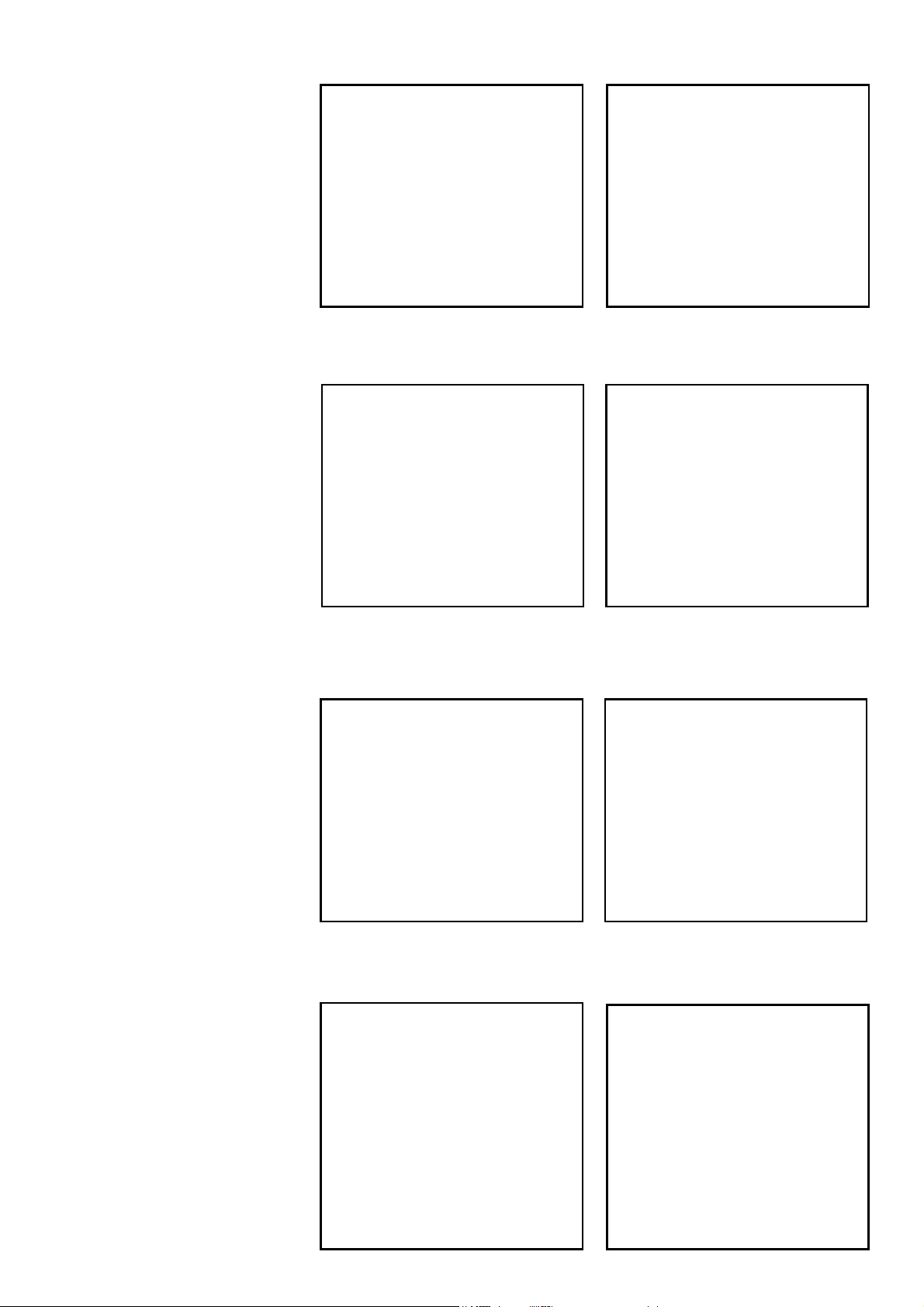
Seite 42
# 22 4367
Steckungsrohr
Wing spar
# 73 3179
Dreiblatt Luftschraube 1
1x5,5“
Propeller 11x5,5“
# 22 4369
Spinner inkl. Spinnerschrauben
Spinner including screws
# 22 4370
Luftschraubenmitnehmer/
Prop adapter
# 22 4375
Splinte /Slpints
# 22 4375
Kleinteilesatz/ small items set
# 82 5884
Aussenläufer E-Motor PERMAX
BL-O 3530-1100
# 7 2234
Regler MULTIcont BL-40 SD
# 22 4367 # 73 3179
# 22 4369 # 22 4370
# 22 4375 # 22 4375
# 82 5884 # 7 2234
Page 43

Seite 43
# 22 4368
Flächenverstrebungen /
wing holders
# 22 4373
Dekorbogen Pilatus PC-6 blau /
Decal sheet Pilatus PC-6 blue
# 22 4374
Dekorbogen Pilatus PC-6 rot /
Decal sheet Pilatus PC-6 red
OPTION:
# 73 3060
Schwimmerset Pilatus PC-6 /
Floats Pilatus PC-6
Page 44

Seite 44
MULTIPLEX Modellsport GmBH & Co. KG. Westliche Gewerbestrasse 1 D-75015 Bretten-Gölshausen
www.multiplex-rc.de
 Loading...