

Page 1
22
Electric model aircraft
MULTIPLEX Modelltechnik GmbH
zz
zz
zNeuer Weg 15
zz
zz
zD-75223 Niefern
zz
zz
zwww.multiplex-rc.de
# 21 4111
The beginner’s model with flair
Super flying qualities
Ideal for the beginner - flies great all by itself
Quick to assemble
Complete it in one afternoon
No finishing required
The model components are moulded in coloured plastic foam, and
come out of the mould as finished items
Can even be flown with only two channels
Fixed elevator
Flies in a very small space - even on a football pitch!
PiCO CUB
PiCO CUB
Version 2 07/2001
GB
Page 2

23
[1. Examine your kit carefully!
MULTIPLEX models are subject to constant quality checks throughout the production process, and we sincerely hope that you are
happy with the contents of your kit. However, we would ask you to check all the parts before you start construction, with reference to
the parts list, as we cannot exchange components which you have already worked on. If you find any part is not acceptable for any
reason, we will readily correct or exchange it once we have examined it. Just send the component to our Model Department. Please be
sure to include a brief description of the fault.
We are constantly working on improving our models, and for this reason we must reserve the right to change the kit contents in terms
of shape or dimensions of parts, technology, materials and fittings, without prior notification. Please understand that we cannot entertain
claims against us if the kit contents do not agree in every respect with the instructions and the illustrations.
Caution!
Radio-controlled models, and especially model aircraft, are by no means playthings in the normal sense of the word. Building
and operating them safely requires a certain level of technical competence and manual skill, together with discipline and a
responsible attitude at the flying field. Errors and carelessness in building and flying the model can result in serious personal
injury and damage to property. Since we, as manufacturers, have no control over the construction, maintenance and operation
of our products, we are obliged to take this opportunity to point out these hazards, and to emphasise your personal
responsibility. Please check that your private third-party insurance policy covers the flying of model aircraft of this type. If you
are not sure, expand your insurance cover, or ask for help from your national body. In the U.K. this is:
British Model Flying Association (BMFA),
Chacksfield House, St. Andrew’s Road, Leicester, LE2 8RE
Telephone: 0116-2440028
E-Mail: admin@bmfa.org
Adhesives:
MULTIPLEX 5-minute epoxy dispenser # 60 2740
and/or
White glue e.g. Bindan express (supplied in the kit)
Tools:
Scissors, combination pliers, balsa knife, screwdrivers (slot-head, cross-point), 3.5 Ø + 4.5 Ø drills,
small round file, 150-grit abrasive paper, sawblade (junior hacksaw).
Specification Wingspan 1160 mm
Fuselage length 785 mm
Wing area (FAI) approx. 28.3 dm²
Weight approx. 590 - 675 g
Wing loading approx. 20 g/dm²
Wing section Benedek mod., thickened
Tailplane section Flat plate
Controls Elevator, rudder and motor
Important note
For all joints involving the styrofoam components it is essential that you avoid the use of solvent-based adhesives, and instant
or cyano-acrylate glue (cyano, or CA) in particular. These materials will melt and destroy a large volume of foam, and the
component will be completely ruined.
Use solvent-free adhesives, such as 5-minute epoxy or white glue.
Using 5-minute epoxy
This adhesive should only be used at normal room temperature. The maximum working time (“pot life”) of the mixed resin is about 5
minutes, so you should only mix up the quantity required for the job in hand. Take great care to mix equal quantities of the two
components, and mix the epoxy quickly and thoroughly. Apply the glue to one side of the joint only, and don’t use excessive amounts.
Press the parts together immediately and tape or clamp the joint for at least 10 minutes. Freshly mixed epoxy can be wiped off the
model readily using methylated spirits on a rag. Do not use any other type of solvent, as the solvent itself may attack and destroy the
foam and ABS parts of your model. Be sure to read and observe the safety notes provided by the adhesive manufacturer.
Using white glue
White glue should be used at normal room temperature. The maximum working time of the glue is about 5 minutes. Apply a thin layer
of the glue to one side of the joint only. Press the parts together immediately and tape or clamp the joint for at least 15 - 30 minutes.
Excess glue can easily be wiped off using water. Don’t use solvent for this, as the foam and vacuum-moulded parts of the kit might be
damaged. White glue is only suitable for gluing wooden parts and styrofoam parts. Be sure to read and observe the safety notes
provided by the adhesive manufacturer.
PiCO CUB - Building instructions
Page 3
24
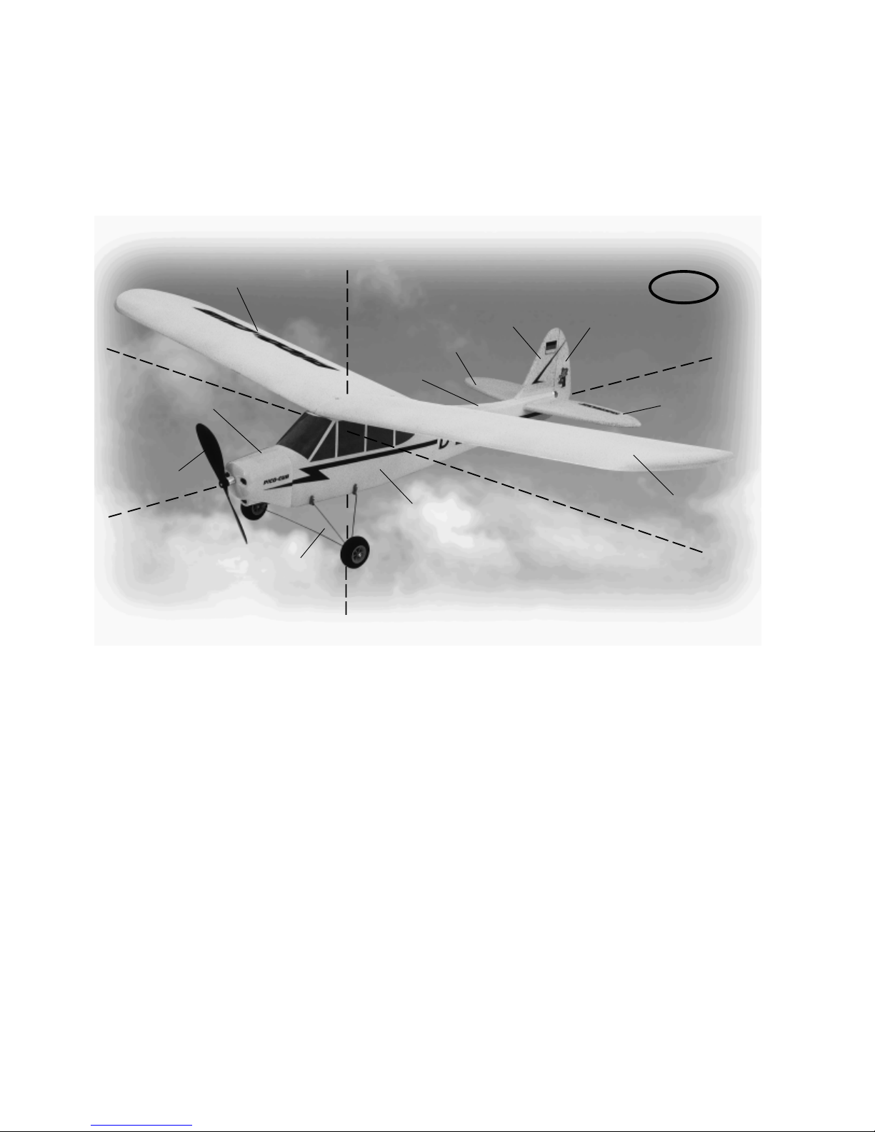
Motor cowl
Propeller
Fuselage
Undercarriage set
L.H. wing panel
Seitenruder
Höhenruder
Fin
Tailplane
Fuselage turtle
deck
R.H. wing panel
Längsachse
Querachse
Hochachse
PiCO CUB
GB
Basic information relating to model aircraft
Any aircraft, whether full-size or model, can be controlled around the three primary axes: vertical (yaw), lateral (pitch) and longitudinal
(roll).
When you operate the elevator, the model’s attitude alters around the lateral axis. If you apply a rudder command, the model swings
around the vertical axis. If you move the aileron stick, the model rolls around its longitudinal axis. As our PICO-CUB has considerable
wing dihedral, ailerons are not required for roll control. In this case the rudder is used both to turn the model around the vertical axis,
and also to roll it (longitudinal axis). External influences such as air turbulence may cause the model to deviate from its intended flight
path, and when this happens the pilot must control the model in such a way that it returns to the required direction. The basic method
of controlling the model’s height (altitude) is to vary motor speed (motor, gearbox and propeller). The rotational speed of the motor is
usually altered by means of a speed controller. Applying up-elevator also causes the model to gain height, but at the same time it
loses speed, and this can only be continued until the model reaches its minimum airspeed and stalls. The maximum climb angle varies
according to the power available from the motor.
Longitudinal axis, lateral axis, vertical axis
Wing section
The wing features a cambered airfoil section over which the air
flows when the model is flying. In a given period of time the air
flowing over the top surface of the wing has to cover a greater
distance than the air flowing under it. This causes a reduction in
pressure on the top surface, which in turn creates a lifting force
which keeps the aircraft in the air. Fig. 1
Centre of Gravity (CG)
To achieve stable flying characteristics your model aircraft must
balance at a particular point, just like any other aircraft. It is
absolutely essential to check and set the correct CG position
before flying the model for the first time.
The CG position is stated as a distance which is measured aft from
the wing root leading edge, i.e. close to the fuselage. Support the
model at this point on two fingertips (or - better - use the MPX
CG gauge, # 69 3054); the model should now hang level. Fig. 2
If the model does not balance level, the installed components
(e.g. flight battery) can be re-positioned inside the fuselage. If this
is still not sufficient, attach the appropriate quantity of trim ballast
(lead or plasticene) to the fuselage nose or tail and secure it
carefully. If the model is tail-heavy, fix the ballast at the fuselage
nose; if the model is tail-heavy, attach the ballast at the tail end of
the fuselage.
The longitudinal dihedral is the difference in degrees between
the angle of incidence of the wing and of the tail. Provided that
you work carefully and attach the wing and tailplane to the
fuselage without gaps (using glue or screws), the longitudinal
dihedral will be correct automatically.
If you are sure that both these settings (CG and longitudinal
dihedral) are correct, you can be confident that there will be no
major problems when you test-fly the model. Fig. 3
Control surfaces, control surface travels
The model will only fly safely, reliably and accurately if the control
surfaces move freely and smoothly, follow the stick movements
in the correct “sense”, and move to the stated maximum travels.
The travels stated in these instructions have been established
during the test-flying programme, and we strongly recommend
that you keep to them initially. You can always adjust them to
meet your personal preferences later on.
Transmitter controls
The transmitter features two main sticks which the pilot moves
to control the servos in the model, which in turn operate the
control surfaces.
The functions are assigned according to Mode A, although other
stick modes are possible.
The transmitter controls the control surfaces as follows:
Rudder (left / right) Fig. 4a
Elevator (up / down) Fig. 4b
Throttle (motor off / on) Fig. 5
Unlike the other controls, the throttle stick must not return to the
neutral position automatically. Instead it features a ratchet so that
it stays wherever you put it. Please read the instructions supplied
with your radio control system for the method of setting up and
adjusting the transmitter and receiving system.
Page 4

25
Assembling the model:
Preparation:
Check all the styrofoam parts carefully, and clean up any rough
edges using 150-grit abrasive paper before starting construction.
Start with the tailplane 15: locate the hinge channel on the
underside, and mark it carefully on the top surface. Run a soft,
rounded-point pencil along the hinge line on the top surface. This
ensures that the foam bends exactly along the recessed line, rather than “giving” randomly around individual foam particles. For
safety’s sake apply a strip of adhesive tape (e.g. Tesa multifilm)
centrally along the top of the hinge line. Repeat the procedure
with the hinge line of the rudder 16.
Fig. 6
At the bottom of the rudder 16 and the tail end of the fuselage
cut a slot for the leaf hinge 27; it should be exactly in line with the
main rudder hinge line.
Fig. 7
Glue the elevator joiner 48 to the elevators using 5-minute epoxy.
Lay the elevators down flat and weight them until the glue has
set hard, to ensure that they are exactly parallel.
Fig. 8
Glue the tailplane and fin 15/16 to the fuselage 5. Hold the
fuselage turtle deck in place to help you position the fin correctly,
but don’t glue the turtle deck in place at this stage. Glue the hinge 27 to the fuselage and rudder as you do this. Check that the
rudder is aligned correctly, and deflects freely to both sides of
neutral. Before the glue sets hard, carefully align the fin and
tailplane relative to the wing (tailplane / fin angle: 90°).
Fig. 9
Completing the fuselage:
Using a small round file (a screwdriver also works well) cut the
tunnels through the fuselage from the motor to the battery box
on the underside of the fuselage, and from the battery box to the
RC compartment.
Fig. 10
The undercarriage reinforcements 44 fit in slots on both sides of
the battery compartment on the underside of the fuselage. Before
installing the reinforcements, use a fine-tooth hacksaw blade to
cut slots 3 mm deep and 1.5 mm wide in them at the marked
points; the undercarriage units fit in these slots later. Drill two 3.5
mm Ø holes in both reinforcements at the marked points. Hold
the undercarriage reinforcements against the outside of the
fuselage, and drill 3.5 mm holes half-way through the styrofoam
from each side, using the reinforcements as a template. The
reinforcements can now be glued in the fuselage using 5-minute
epoxy. Cut two pieces of 3/2 mm Ø plastic tube 64 80 mm long,
and push them through the fuselage at front and rear to form
undercarriage attachment dowels. Set the tubes central while the
epoxy is still soft. Cut slots across the underside of the fuselage
for the undercarriage legs, using the 3 x 1.5 mm slots in the
reinforcements as a guide.
Fig. 11
Installing the RC system components in the fuselage:
The rudder and elevator control systems are based on the “snakes”
60/61, which run through holes cut in the tail end of the fuselage.
In order to position these holes accurately it is necessary to install
the servos in the fuselage. Screw the two servos to the mounting
rails 47 and check that this assembly fits in the fuselage. Shorten
the rails if necessary. Finally glue the servo rails 47 to the fuselage
sides, with the servos still attached.
Fig. 12a
If your model is # 21 4048, the kit does not include the RC system
components. In this case you can decide for yourself whether to
install individual servos or an “Einstein” or “The Brick” module (=
MULTIPLEX module containing receiver, two servos and switch).
Fig. 12b
Using side-cutters, a short pair of scissors or a saw blade, cut off
the lower part of the T-piece of the horns 20 leaving just a short
stub. Fit a pushrod connector 32 in the outermost hole of the
elevator and rudder horns 20. Slip the M2 washers 33 over the
threaded shank, then fit and tighten the nuts 34. Fit the socketcap screws 35 in the threaded hole in the pushrod connectors,
and tighten them using the allen key 76. Now glue the horns in
the recesses moulded into the control surfaces, with the row of
holes facing forward in each case.
Fig. 13
The holes for the snake outers 60/61 must be positioned to give
the wire pushrods 62/63 as straight a run as possible from the
servos to the control surfaces. The linkages must run smoothly
and easily.
Pierce the tunnels at the tail end of the fuselage using a small
round file or a screwdriver, and temporarily fit the snakes. Note
the position of the rudder and elevator horns 20 when you do
this. The snake outers should exit the fuselage side about 85 mm
forward of the tail end of the fuselage. Slip the pushrods (0.8 mm
Ø steel wire) into the outers and check that they run smoothly.
When you are satisfied, glue the snake outers to the fuselage using
5-minute epoxy.
Fig. 14
Form a Z-bend in one end of each of the steel pushrods, and
connect them to the fourth hole of the servo output arm (approx.
10 mm from the pivot axis).
If you are using an “Einstein” or “The Brick” module, bend the final
5 mm of the pushrods 62/63 at 90° at the servo end, and connect
them to the servo output arms (second hole from the centre approx. 10 mm lever length), fitting the plastic spacers 29 (0.8 to
1.6 mm) at the same time. Secure them with a drop of 5-minute
epoxy.
Fig. 12b
Check that the fuselage turtle deck 6 is a snug fit, trim it if
necessary, and glue it to the fuselage using 5-minute epoxy. While
you have a little spare epoxy mixed up, glue the tailskid 45 into
the tail end of the fuselage.
Fig. 15
The wing is attached to the fuselage by plastic screws which
engage in the wing plates 41 + 42; press the captive nuts 21 into
these and glue them with 5-minute epoxy. At the same time glue
the wing plates in the recesses in the fuselage. Be sure to keep
the epoxy out of the threaded part of the nuts.
Fig. 16
Page 5

26
Installing the motor (# 21 4111 only):
The standard power system for the model is the direct-drive Permax 400 6V motor 71. The first step is to separate the motor plate
49 from the die-cut sheet; note that the in-fill piece 50 is not
required and should be cut out. The motor plate should butt up
against the fuselage at the rear. The bulkhead is intentionally
narrower than the surface on which it rests; this allows for the
thickness of the motor cowl, which is fitted later. Check that the
motor fits snugly in the motor plate, and glue the parts together
by applying a narrow fillet of 5-minute epoxy on both sides.
Fig. 17a
Run the motor power leads back into the battery compartment.
Temporarily fit the motor cowl, and adjust the position of the
motor and motor plate if necessary. When you are satisfied, glue
the motor plate to the fuselage using 5-minute epoxy.
Installing a motor with integral circular controller
If your power system includes a motor with integral circular
controller, it can be mounted as follows: the motor bulkhead 49/
50 is not used, and instead the wooden spacer 53 is glued in the
motor well, flush at the front. The motor can now be placed on
this and positioned accurately: it should project by 12 mm at the
front. Check this by fitting the motor cowl over it. When everything
fits, glue the motor to the foam on both sides and the wooden
spacer 53 at the bottom with a small fillet of 5-minute epoxy. Use
a small strip of tape to hold it in place while the glue sets.
Fig. 17b
Optional upgrade:
If you decide to install a geared motor, leave the in-fill piece 50
in the motor plate rather than cutting it out. Apply a few drops of
cyano to the die-cut slots to restore the plate’s strength. Drill 2.5
mm Ø holes in the motor plate at the punched points. With the
motor plate in position on the fuselage, hold the geared motor
against the plate. Drill 2 mm Ø holes in the gearbox flange, working
through the existing holes in the motor plate, and fix the gearbox
to the plate using the screws 28. Place this assembly in the
fuselage again, and ascertain the correct position with the help
of the motor cowl, as described earlier. Check that the motor plate
rests flat on the fuselage, and open up the space under the motor
slightly if necessary. The motor case should end flush with the
front face of the fuselage. When you are sure that everything fits
correctly, glue the motor plate to the fuselage using 5-minute
epoxy.
Fig. 18
Motor cowl:
Cut out the cowl 7 and drill holes at the marked points. If you
have installed a geared motor, open up the hole for the output
shaft to the larger marked diameter. Check that the cowl fits really
accurately, trim where necessary, then drill 2.5 mm Ø holes on
both sides for the retaining screws. Screw the cowl to the retaining
plates 51 using the screws 28, then apply 5-minute epoxy to the
edge of the plates facing the fuselage. Taking care not to wipe
the epoxy off, position the motor cowl on the model, push it back
into position on both sides and tape it to the fuselage. This ensures
that the cowl retaining plates are correctly positioned. Allow the
epoxy to set hard, then undo the screws to remove the cowl.
Fig. 19
Installing the undercarriage:
The undercarriage is assembled from the wire legs 80 - 82 and
the spacer sleeves 84. A simple jig is required to ensure correct
alignment. Take a piece of card and draw two parallel lines on it
spaced 100 mm apart. The undercarriage legs are later glued
together and taped down directly over these lines.
Sand the ends of the undercarriage legs, fit the washers 86 on
them, apply 5-minute epoxy, then fit the spacer sleeves 84 and
the wheels 83, and fit the screws 85 while the glue is still soft. Be
sparing with the epoxy, and on no account allow it to get onto
the outside of the spacer sleeves. It is a good idea to grease the
outside of the sleeves lightly before gluing the parts together, as
this effectively prevents them becoming stuck to the wheels. Align
the undercarriage components accurately and leave the assembly
until the epoxy has set hard.
Fig. 20
Joining the wing panels
The first step is to assemble the spar 40 from the two strips of
balsa supplied. Work carefully, exactly as shown in the drawing,
and weight the parts down flat until the glue has set hard.
Fig. 21
Check that the wing panels 10/11 fit together accurately, and trim
the root faces slightly if necessary so that the panels fit together
without any gaps. Pack up one wing tip by about 12 cm, e.g. on a
pile of books, to produce the correct dihedral of about 12°. Use
the prepared spar to aid alignment.
Place the vacuum-moulded wing reinforcement 12 over the rear
part of the wing to fill the opening, and glue the moulding in
place from the underside using 5-minute epoxy. Glue the in-fill
strip 52 in the wing reinforcement at the same time.
Glue the prepared spar and the front wing reinforcement 43 (hole
facing wing leading edge) in the wing. When the glue has set hard,
drill a 4.5 mm Ø hole vertically through the foam from the
underside. Open up this hole on the top surface to accept the
screw sleeve 26.
Fig. 22
Seal the hole in the front wing reinforcement 43 with a strip of
tape, and fill it with epoxy to the point where there is still just
enough space for the reinforcing sleeve 26 itself. Push the sleeve
into place and carefully wipe off excess resin. Apply a strip of
adhesive tape over the top until the glue has set hard. When the
glue has cured, remove the tape and run a 4.5 mm Ø drill bit
through the sleeve and the front reinforcement to clear the hole.
Cut a hole in the recess in the top of the vacuum-moulded rear
reinforcement. Check that the holes line up with the captive nuts
in the fuselage when the wing screws 24/25 are fitted. Trim the
holes as necessary to compensate for any inaccuracy in
construction.
Assembling the model:
Using 5-minute epoxy, glue the “hook” tape 22 in the battery
compartment to take the speed controller and flight pack. Note
that the adhesion of the self-adhesive tape is not sufficient by
itself on styrofoam; glue is required.
Attach the undercarriage using the four rubber bands 30: fit a
rubber band over one of the undercarriage dowels, wind it round
the dowel and the undercarriage leg as many times as possible
whilst keeping the band slightly taut, then slip it over the dowel
again. Repeat the procedure with the other three dowels.
Fig. 23
You are now ready to carry out the first test run using the radio
control system.
Page 6

27
48
15
1
27
2
3
4a
6
7 8
4b
Auftriebskraft
X
α
5
Page 7

28
9
10
11
14
13
16
34
31
33
32
20
15
5
44
44
47
61
60
64
44
44
44
12b
12a
60/61
29
60/61
Page 8

29
50
18
19
17a
7
51
51
49
71
17b
16
21
42
41
53
12mm
15
32
49
Page 9

30
20
22
21
24
23
40
11 10
2
25
26
64
81
30
82
80
84
86
83
85
81
26
25
24
12
52
43
12
Page 10

31
Connect the power cables from the motor to the speed controller,
and stow the wires away neatly so as to save space. Connect the
controller to the receiver and the flight battery, and carry out an
initial “test-run” of the working systems. Check the direction of
rotation of the motor, and the “sense” of the rudder and elevator
(right stick = right rudder etc.). Correct the control surface neutrals
if necessary. To do this first set the servo output arms to neutral,
and then adjust the control surfaces using the pushrod connectors
32 - 34 (using the allen key 35).
The last job is to mount the propeller 70 on the output shaft:
start by sanding the motor shaft using fine abrasive paper. Apply
a little 5-minute epoxy to the propeller hub on the tip of a pin,
then push the propeller onto the shaft as far as it will go.
Wait until the epoxy has set hard before running the motor.
Wing struts, aerobatics and flight loads
The PiCO Cub is designed primarily as a gentle park-fly model,
and for indoor flying in large halls. In either case the wings do not
need the additional strength afforded by working struts. However,
if you intend flying simple aerobatics with your PiCO Cub, or if
relatively abrupt pull-out manoeuvres are likely because you are
going to use the model for teacher-pupil flying, we recommend
that you install wing struts, otherwise the wings could fail under
stress in the air.
The first step is to cut slots in the wing for the horns 38. They
should be located 25 cm from the centre of the wing, 5 cm back
from the wing leading edge, and pointing towards the rear
undercarriage mounting. Cut the slots with a balsa knife, tease
out the foam with a small screwdriver, and then glue the horns in
the slots using 5-minute epoxy. Cut two 500 mm lengths of 0.8
mm Ø steel wire 55, and solder a threaded coupler 36 to one end
of each. Screw the M2 clevises 37 on the couplers, and connect
them to the horns mounted in the wings. Fit the other end of the
wire strut in the slot for the rear undercarriage leg, where it is
held in place by the same rubber bands. Bend the wire slightly on
each side of the fuselage so that the struts run straight from the
fuselage to the wing. Adjust the clevises so that the wing is under
no more than very slight downward tension.
Even with the struts fitted, the CUB is not permitted to fly
negative-G manoeuvres - this applies to full-size aircraft of
the same class, too. (Negative manoeuvres: inverted flight,
outside loops etc.)
Finally - giving the model that finishing touch:
The kit is supplied with a decal sheet, part 2. Cut out the individual
name placards and emblems and apply them to the model in the
arrangement shown in the illustrations, or use your own
imagination. The cabin window decals include marks which will
help you position them correctly. You will see a fine line on either
side of the side windows, and these should be cut out together
with the decals. Position the rear line on the edge of the fuselage.
The front lines are a guide to the location of the front screen.
Fig. 24
Centre of Gravity (CG), control surface travels:
As with all aircraft, your “PiCO Cub” offers inherently stable flying
characteristics, but only if balanced at the correct point. Assemble
the model completely, ready to fly, and install the flight battery.
Support the model under the wing spar on two fingertips. The
model should now balance level, i.e. should not tip forward or
back.
(CG = 60 mm aft of the wing root leading edge, +/- 5 mm).
If you need to correct the CG, it is permissible to add a few
grammes of lead ballast to the nose or tail.
Fig. 25
The travel of the control surfaces should be as follows, measured
at the widest point of the panels:
Rudder = +/- 18 mm
Elevator = +/- 12 mm
Pre-flight preparations
Wait for a day with flat calm conditions, or only a very slight breeze.
The evening hours often provide the most favourable conditions.
Be sure to carry out a range check before attempting the first
flight:
Charge up the transmitter and flight batteries in the prescribed
manner. Before you switch on the transmitter, ensure that no other
modeller is already using that channel.
Collapse the transmitter aerial completely, and ask your assistant
to walk away from the model holding the transmitter.
Ask your assistant to operate one control function constantly,
while you watch the servos carefully: the non-controlled one
should remain stationary up to a distance of about 80 m, and the
controlled one should follow the transmitter stick movements
smoothly and immediately. This test only gives valid results if the
radio band is clear of interference, and if no other radio control
systems are in use, even on other channels. Repeat the test with
the motor running. The effective range should still be at least 70m.
If you are not sure that all is well, do not be tempted to fly the
model. Send the entire system, complete with battery, switch
harness and servos, to the RC system manufacturer’s Service
Department for checking.
The first flight ...
Hand-glides do not give useful results with this model.
The model should be hand-launched (always into the wind).
If you have not flown a radio-controlled model before, please
ask an experienced pilot to help during the initial stages.
Fig. 26
Allow the model to climb to a safe altitude, then adjust the controls
using the trim sliders on the transmitter until the model flies
straight ahead “hands off”.
At a safe height switch the motor off and fly the model on the
glide to get a “feel” for the model’s control response on the landing
approach. Carry out a series of simulated landing approaches at
a reasonable height, so that you will be prepared for the landing
when the flight pack actually runs out.
Until you are confident of the model’s control response, do not
attempt tight turns close to the ground, especially when you are
landing. It is far better to land safely some distance away, than to
force the model back to your feet and in so doing crash it.
If the landing is not quite perfect ...
If the model suffers a really hard landing it may well suffer damage;
one of the tail panels or even a wing may break off entirely. Don’t
panic: five-minute epoxy can be used on the field to get you back
in the air quickly.
Apply a little 5-minute epoxy to the broken surfaces, push the
parts together and hold for about five minutes. Leave the glue to
cure for a further 10 minutes - and you’re ready to fly again.
Don’t use too much epoxy; excess glue doesn’t make the joint
stronger, and it usually looks awful.
If you have time to repair the joint at your leisure, it is better to
use white glue to re-join the broken parts. White glue makes an
almost invisible joint, but you must leave the glue overnight to
harden, and this means jigging or packing the model up to
prevent the parts slipping out of alignment.
Page 11

32
Safety
Safety is the First Commandment when flying any model aircraft.
Third party insurance should be considered a basic essential. If
you join a model club suitable cover will usually be available
through the organisation. It is your personal responsibility to
ensure that your insurance is adequate (i.e. that it covers powered
model aircraft).
Make it your job to keep your models and your radio control
system in perfect order at all times. Check the correct charging
procedure for the NC batteries used in your RC set. Make use of
all sensible safety items and precautions which are advised for
your system. An excellent source of practical accessories is the
MULTIPLEX main catalogue, as our products are designed and
manufactured exclusively by practising modellers for other
practising modellers.
Always fly with a responsible attitude. You may think that flying
low over other people’s heads is proof of your piloting skill; others
know better. The real expert does not need to prove himself in
such childish ways. Let other pilots know that this is what you
think too. Always fly in such a way that you do not endanger
yourself or others. Bear in mind that even the best RC system in
the world is subject to outside interference. No matter how many
years of accident-free flying you have under your belt, you have
no idea what will happen in the next minute.
We - the MULTIPLEX team - hope you have many hours of pleasure
building and flying your new model.
MULTIPLEX Modelltechnik GmbH
Klaus Michler
Model Development
PiCO-Cub replacement parts list
Motor cowl#72 4308
Undercarriage and wheels # 72 4309
Wooden parts and fittings # 72 4310
Decal sheet # 72 4311
Moulded fuselage and tail components # 21 4311
Moulded wing panels # 21 4310
Replacement parts can be ordered through your local model shop.
The Complete Set (A+B+C = All-In Pack) - PICO CUB
A+B+C 35 MHz # 1 3023
A+B+C 40/41 MHz # 1 3024
A - PICO CUB complete model
- Kit of ready-made components
- Decal sheet
- Electric motor and propeller
- Speed controller for motor
- 2 servos
- Battery (flight pack)
B - PiCO-line radio control system
- Transmitter and NC battery, 35 MHz or 40/41 MHz
- HC charge lead
- PICO 4/5 receiver
- Pair of crystals to choice (# 160+channel)
C - PiCO-line Auto-Charger
- For recharging transmitter and flight battery from 12 V (e.g. car
battery)
Parts list - radio control system and accessories
Applies to # 1 3023 and # 1 3024
Part No. Description Type
No. off
90 1 Radio control system Pico-Line
91 1 Receiver Pico 4/5 UNI
92 2 Servos MS-X3 UNI
93 1 Speed controller Pico-control 400 round UNI
94 1 Pair of cr ystals 35 / 40 / 41 MHz (to choice)
95 1 Charge lead HC (high-current)
96 1 Battery charger Pico-Line Auto-Charger
Page 12

33
Optional accessories
Please refer to our brochures, flyers and catalogues for information
about currently available accessories and extra equipment.
PiCO-line transmitter tray# 8 5039
- Carbon-look plastic with support bars, neckstrap and fittings
PiCO CUB “Tuning”:
If you equip the model with the 400L geared motor you can obtain
longer flight times from the same size of battery.
At the same time the motor provides more thrust for ground takeoffs and powerful climbs.
If you wish to use the optional floats we strongly recommend
that you install the 400L geared motor.
Flight battery 7/500 AR HC
# 15 5648
400L gearbox alone # 33 2690
- 2.3:1 gearbox (excl. motor and propeller) - use motor supplied
in the kit.
See below for suitable propeller
- Detailed assembly instructions
Propeller for 400L geared motor # 73 2691
- 7 x 6.5” propeller alone
or: 400L geared motor, complete# 33 2691
- 2.3:1 gearbox with Permax 400 / 6 V and 7 x 6.5” propeller
- Detailed assembly instructions
or: 400L geared motor, with PiCO-Control 380 round speed
controller (UNI) # 33 2692
- 2.3:1 gearbox with Permax 400 / 6 V and 7 x 6.5” propeller
- With factory-fitted speed controller and gearbox
- Detailed assembly instructions
Float kit # 73 3068
- Moulded Elapor components
- Set of wire parts and fittings
- Detailed instructions
Page 13

34
Parts list - PICO-CUB
Part No. Description Material Dimensions
No. off
1 1 Building instructions A4
2 1 Name placard / decal set Printed adhesive film Ready made
Fuselage
5 1 Fuselage Moulded styrofoam Ready made, yellow
6 1 Fuselage turtle deck Moulded styrofoam Ready made, yellow
7 1 Motor cowl Vac. moulded plastic Ready made
Wings
10 1 L.H. wing panel Moulded styrofoam Ready made, yellow
11 1 R.H. wing panel Moulded styrofoam Ready made, yellow
12 1 Wing reinforcement Vac. moulded plastic Ready made
Tail panels
15 1 Tailplane Moulded styrofoam Ready made, yellow
16 1 Fin Moulded styrofoam Ready made, yellow
Accessories
20 2 Glue-fitting horn Plastic Ready made
21 2 Captive nut Metal M4
22 2 Velcro tape, “hook” Plastic 25 x 60 mm
23 2 Velcro tape, “loop” Plastic 25 x 60 mm
24 1 Cheesehead wing screw Plastic M4 x 20 mm
25 1 Countersunk wing screw Plastic M4 x 20 mm
26 1 Reinforcing bush for wing screw Plastic Ready made
27 1 Plastic leaf hinge Plastic Ready made
28 9 Cowl / gearbox screw Metal 2.2 x 6.5 mm
29 2 Pushrod retainer sleeve Plastic Ready made
30 4 Rubber bands for undercarriage Rubber 1 x 1 x 15 mm Ø
31 2 screw Metal M 3 x 3 mm
32 2 Pushrod connector Metal Ready made
33 2 M2 washer Metal Ready made
34 2 Self-locking nut Metal M2
35 1 Allen key Metal 1.5 mm A/F
36 2 Threaded coupler Metal M2
37 2 Clevis Plastic Ready made
38 2 Wing strut horn Plastic Ready made
Wooden parts
40 1 Spar (two parts) Hard balsa Ready made
41 1 Front wing plate Plywood Die-cut, 3 mm
42 1 Rear wing plate Plywood Die-cut, 3 mm
43 1 Front wing reinforcement Plywood Die-cut, 3 mm
44 2 Undercarriage reinforcement Plywood Die-cut, 3 mm
45 1 Tailskid Plywood Die-cut, 3 mm
46 1 Pushrod support Plywood Die-cut, 3 mm
47 2 Servo support rail Balsa 10 x 12 x 35 mm
48 1 Elevator joiner Obechi 5 x 5 x 50 mm
49 1 Motor plate Plywood Die-cut, 3 mm
50 1 Motor plate in-fill piece Plywood Die-cut, 3 mm
51 2 Motor cowl screw plate Plywood Die-cut, 3 mm
52 1 Reinforcement Balsa 6 x 6 x 60 mm
53 1 Wooden spacer (motor mount) Balsa 10 x 17 x 45 mm
Wire and rod
60 1 Rudder snake outer sleeve Plastic 2/1 Ø x 500 mm
61 1 Elevator snake outer sleeve Plastic 2/1 Ø x 500 mm
62 1 Rudder pushrod Metal 0.8 Ø x 500 mm
63 1 Elevator pushrod Metal 0.8 Ø x 500 mm
64 1 Undercarriage dowel (tube) Plastic 3/2 Ø x 200 mm
65 1 Bracing wire Metal 0.8 Ø x 500 mm
Power set
70 1 Propeller Plastic 125 x 110 mm
71 1 Electric motor Permax 400 6V Ready made
Undercarriage set
80 1 Front undercarriage unit Spring steel Pre-formed, 55 mm
81 1 Rear undercarriage unit Spring steel Pre-formed, 90 mm
82 1 Undercarriage spreader Spring steel 1.3 Ø x 250 mm
83 2 Wheels Plastic 51 mm Ø
84 2 Spacer sleeves Brass 4 Ø x 0.45 x 17 mm
85 2 Screws Steel M3x6 DIN 84 4.8 ZN
86 2 Washer Brass M3
Page 14

35
20 (2x) 21 (2x) 22(2x) + 23 (2x) 24 (1x) 25 (1x)
26 (1x)
27 (1x)
30 (4x)
28 (8x)
32 (2x) 33 (2x) 34 (2x)
35 (1x)
31 (2x)
40 (1x)
40 (1x)
48 (1x)
52 (1x)
47 (2x)
51
46
49
45
44
42
43
41
50
44
51
29 (2x)
53 (1x)
36 (2x)
37 (2x) 38 (2x)
 Loading...