

Multiplex ND21TS04, ND21RS00, ND21RS02, ND21TS03, ND21TS01 Installation, Operation & Maintenance Manual
...Page 1
Nitrogen Beverage Dispensers
Installation, Operation & Maintenance Manual
This manual is updated as new information and models are released. Visit our website for the latest manual.
Original Document
Part Number: 9290312 October/22/2018
Page 2
Safety Notices
DEFINITIONS
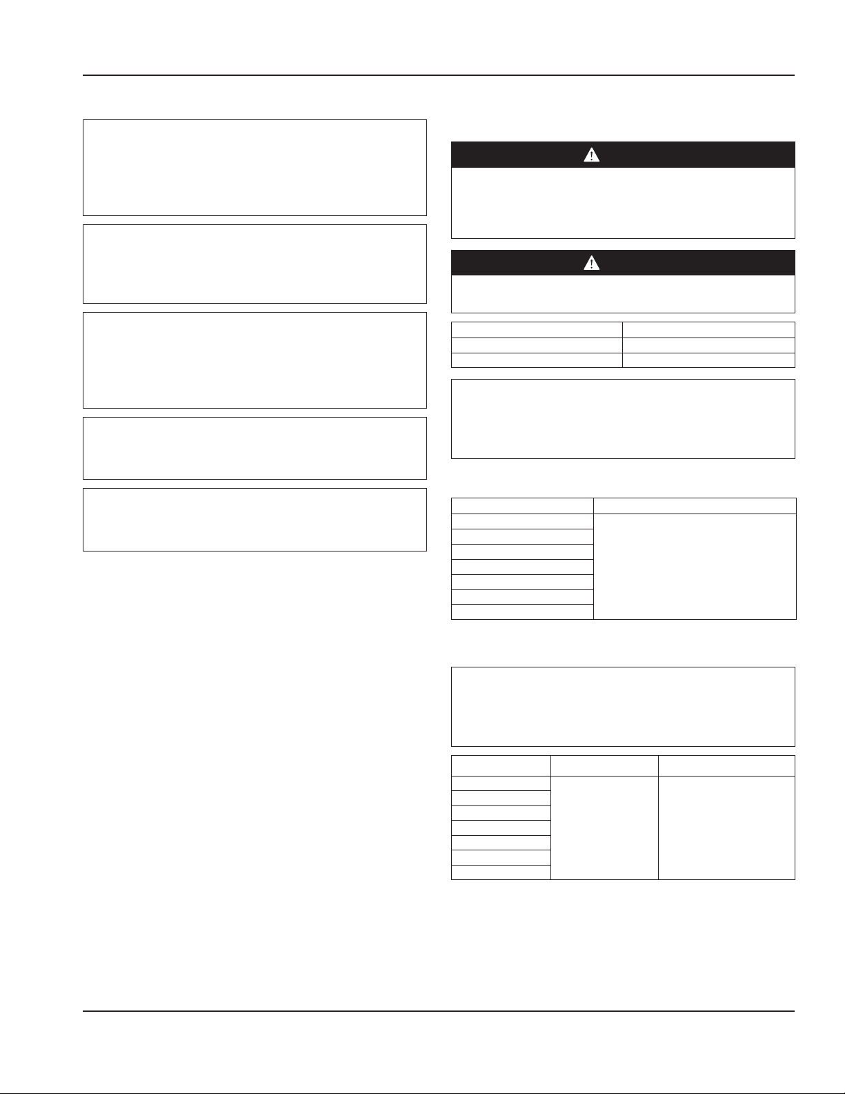
DANGER
Indicates a hazardous situation that, if not avoided, will
result in death or serious injury. This applies to the most
extreme situations.
Warning
n
Indicates a hazardous situation that, if not avoided,
could result in death or serious injury.
NOTE: Indicates useful, extra information about the procedure you are performing.
Indicates a hazardous situation that, if not avoided,
could result in minor or moderate injury.
Indicates information considered important, but not
hazard-related (e.g. messages relating to property
damage).
Caution
,
Notice
Page 3

Section 1
General Information
Section 2
Installation
Table of Contents
Safety Notices ..................................................................................................................... 2
Definitions.................................................................................................................................................2
Read This Manual ............................................................................................................... 5
About N2Fusion™ ................................................................................................................ 5
Unit Inspection ................................................................................................................... 5
Model Numbers .................................................................................................................. 5
Serial Number Location ..................................................................................................... 5
Warranty Information ........................................................................................................ 5
Specifications .....................................................................................................................6
Dimensions ...............................................................................................................................................6
Capacity & Weight ..................................................................................................................................6
Product Delivery Location ...................................................................................................................7
Refrigerant Charge .................................................................................................................................7
Electrical ....................................................................................................................................................8
Section 3
Operation
Step-by-Step Installation .................................................................................................11
Pre-installation Checklist .................................................................................................................. 11
Remote Tower Installation ............................................................................................................... 12
Nitrogen Regulator & Tank Assembly ..........................................................................................13
Nitrogen Installation/Replacement .............................................................................................. 13
Nitrogen Connections & Pressures ...............................................................................................14
N2 Quick Disconnect & Drain ........................................................................................................... 14
Keg & Pump Regulators .................................................................................................................... 15
Keg Connections ................................................................................................................................. 15
Plumbing Diagram ..............................................................................................................................17
Door Hinge Reversal........................................................................................................................... 18
Machine Operation ..........................................................................................................19
Controls/Programming/Settings ................................................................................................... 19
Prime / Clean Button .......................................................................................................................... 19
Clearing Error Code ............................................................................................................................ 20
Priming the System ............................................................................................................................20
Taps & Nozzles ...................................................................................................................................... 20
Keg Change ........................................................................................................................................... 21
Nitrogenator ......................................................................................................................................... 22
Part Number: 9290312 October/22/2018 3
Page 4

Section 4
Maintenance
Section 5
Troubleshooting
Table of Contents (continued)
Cleaning & Sanitizing ....................................................................................................... 23
General Cleaning ................................................................................................................................. 24
Cleaning Supplies ............................................................................................................................... 24
Manual Keg Cleaning ......................................................................................................................... 25
Level 1 - Daily Cleaning ..................................................................................................................... 26
Level 2 - Weekly Cleaning (Single Step Method) ..................................................................... 29
Level 2 - Weekly Cleaning (Three Step Method) ...................................................................... 31
Level 3 - Monthly Cleaning .............................................................................................................. 34
Other Operations ............................................................................................................. 35
Doors & Hinges .................................................................................................................................... 35
Troubleshooting Charts ...................................................................................................37
Dispensing Issues ................................................................................................................................ 37
Refrigerator Cabinet Issues .............................................................................................................. 38
Pouring ....................................................................................................................................................39
4 Part Number: 9290312 October/22/2018
Page 5
Section 1
General Information
Read This Manual
Manitowoc Foodservice developed this manual as a
reference guide for the owner/operator and installer of this
equipment. Please read this manual before installation or
operation of the machine. A qualified service technician
must perform installation and start-up of this equipment.
Consult Section 4 within this manual for service assistance.
If you cannot correct the service problem, consult
Manitowoc KitchenCare at 1-844-724-CARE. Always have
your model and serial number available when you call.
Your Service Agent _______________________________
Service Agent Telephone Number ____________________
Your Local Distributor______________________________
Distributor Telephone Number ______________________
Model Number __________________________________
Serial Number ___________________________________
Installation Date _________________________________
About N2Fusion™
Class A: EMC Registration is done on this equipment for business
use only (Class A). Product seller and user should notice that this
equipment is not for household use.
Model Numbers
This manual covers the following models:
N2Fusion™ Nitrogen Beverage Dispenser
ND21TS00, ND21TS01, ND21TS02, ND21TS03, ND21TS04,
ND21RS00, ND21RS02
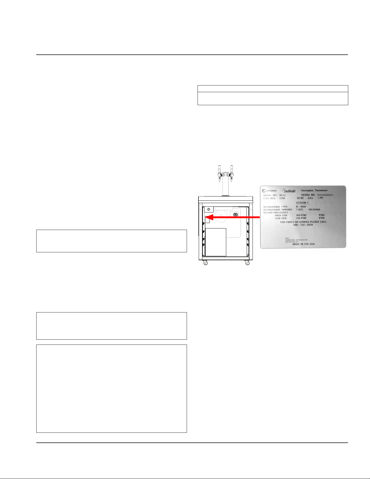
Serial Number Location
The serial number on N2Fusion™ Nitrogen Beverage
Dispenser is printed on the left side of the interior wall.
Always have the serial number of your unit available
when calling for parts or service.
Unit Inspection
Thoroughly inspect the unit upon delivery. Immediately
report any damage that occurred during transportation
to the delivery carrier. Request a written inspection report
from a claims inspector to document any necessary claim.
See “Warranty Information” on page 5.
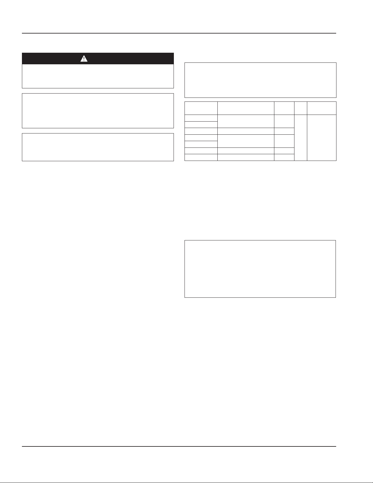
Warning
n
Do not damage the refrigeration circuit when installing,
maintaining or servicing the unit.
Warning
n
Do not operate equipment that has been misused, abused,
neglected, damaged, or altered/modified from that of
original manufactured specifications.
This appliance is not intended for use by persons (including
children) with reduced physical, sensory or mental
capabilities, or lack of experience and knowledge, unless
they have been given supervision concerning use of the
appliance by a person responsible for their safety. Children
should be supervised to ensure that they do not play with
the appliance.
Sample Serial Tag
Warranty Information
Consult your local Service Agent or Representative for terms
and conditions of your warranty. Your warranty specifically
excludes all general adjustments, cleaning, accessories and
related servicing.
Your warranty card must be returned to activate the
warranty on this equipment. If a warranty card is not
returned, the warranty period can begin when the
equipment leaves the factory.
No equipment may be returned without a written Return
Materials Authorization (RMA). Equipment returned without
an RMA will be refused at the dock and returned to the
sender at the sender’s expense.
Please contact your local distributor for return procedures
“Part Number: 9290312” October/22/2018 5
Page 6
General Information Section 1
Specifications
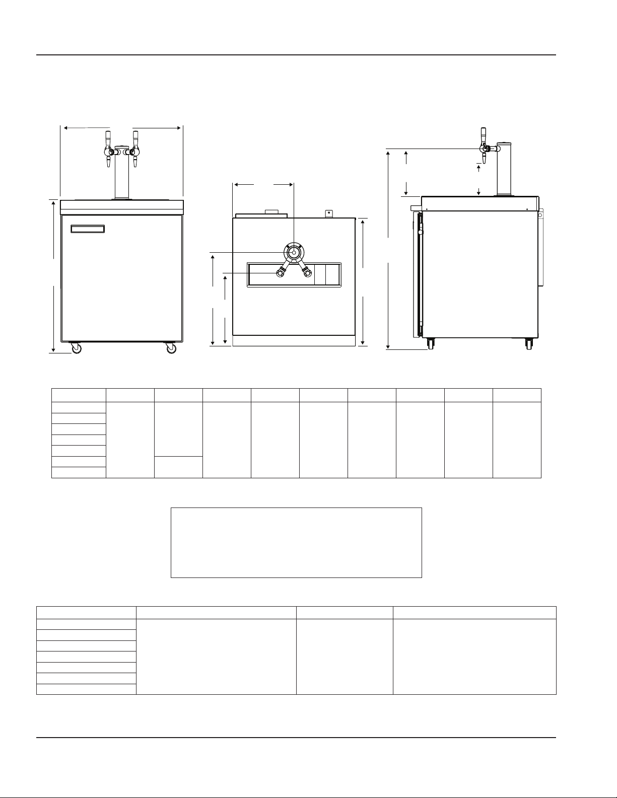
DIMENSIONS
A
H
F
I
G
B
C
D
E
Model A B C D E F G H I
ND21TS00
ND21TS01
ND21TS02
ND21TS03
ND21TS04
ND21RS00 30.75"
ND21RS02
27.3"
(69 cm)
34.0"
(86 cm)
(78 cm) *
28.4"
(72 cm)
20.7"
(53 cm)
13.6"
(35 cm)
16.1"
(41 cm)
44.6"
(113 cm)
10.6"
(27 cm)
7.3"
(19 cm)
* This dimension represents units using 1.25" (3.175 cm) low profile casters, regular casters are 1.25" (3.175 cm) taller.
Warning
n
To avoid instability the installation area must be capable
of supporting the weight of the equipment. Additionally
the equipment must be level side to side and front to
back.
CAPACITY & WEIGHT
Model Max Capacity Volume Weight
ND21TS00
ND21TS01
ND21TS02
ND21TS03
ND21TS04
ND21RS00
ND21RS02
3 - 3 Gallon (11.36L) Coffee Kegs 5.7Ft3 (161L) 168lbs (76kg)
6 Part Number: 9290312 October/22/2018
Page 7
Section 1 General Information
PRODUCT DELIVERY LOCATION
Warning
n
This equipment must be positioned so that the plug is
accessible unless other means for disconnection from
the power supply (e.g., circuit breaker or disconnect
switch) is provided.
Warning
n
Adequate means must be provided to limit the
movement of this appliance without depending on or
transmitting stress to the electrical conduit or gas lines.
Warning
n
To avoid instability the installation area must be capable
of supporting the combined weight of the equipment
and product. Additionally the equipment must be level
side to side and front to back.
Warning
n
This equipment is intended for indoor use only. Do not
install or operate this equipment in outdoor areas.
Warning
n
Do not position the air intake vent near steam or heat
exhaust of another appliance.
The location selected for the equipment must meet the
following criteria. If any of these criteria are not met, select
another location.
• Units are intended for indoor use only.
• The location MUST be level both front to back and side to
side, stable and capable of supporting the weight of the
equipment.
• Position the equipment so it will not tip or slide.
• Recommended air temperature is 41° - 86°F (5° - 30°C), and
must not exceed 90°F (32°C), climate class 4.
• Location must have proper ventilation, DO NOT install in an
enclosure/enclosed cabinet with no access to ambient air.
• The location must not be near heat-generating equipment
or in direct sunlight and must be protected from weather.
• Verify floor of install location is within 1/2" (1.3 cm) of level
front to back, side to side.
• Keep equipment area clear of combustible material.
• Do not install the equipment directly over a drain. Steam
rising up out of the drain will adversely affect operation, air
circulation, and damage electrical /electronic components
• Do not install in an area where a high-pressure water jet
could be used for cleaning.
Clearances
DANGER
Minimum clearance requirements are the same for
noncombustible locations as for combustible locations.
The flooring under the appliance must be made of a
noncombustible material.
DANGER
Risk of fire/shock. All minimum clearances must be
maintained. Do not obstruct vents or openings..
Sides 0" (0 cm)
Back 3" (76 mm)
Front 30" (76 cm)
Warning
n
Do not obstruct machine vents or openings this includes
installing in an enclosed cabinet where the unit will not
have access to ambient air.
Heat of Rejection
Model BTU/hr
ND21TS00
ND21TS01
ND21TS02
ND21TS03
ND21TS04
ND21RS00
ND21RS02
REFRIGERANT CHARGE
1430 (0.42 kW)
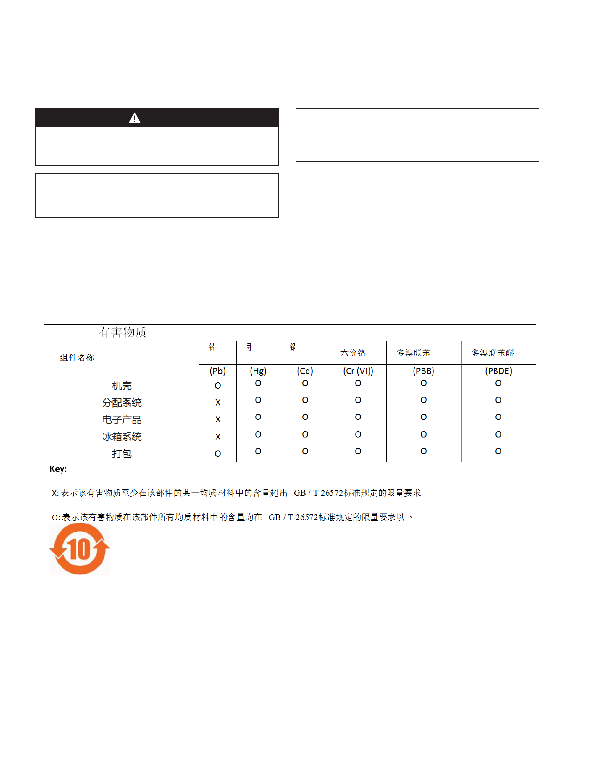
Important
Due to continuous improvements, this information is for
reference only. Please refer to the serial number tag to
verify.
Model Type Refrigerant Charge
ND21TS00
ND21TS01
ND21TS02
ND21TS03
ND21TS04
ND21RS00
ND21RS02
R404A 7.0 oz (198g)
Part Number: 9290312 October/22/2018 7
Page 8
General Information Section 1
ELECTRICAL
DANGER
Check all wiring connections, including factory
terminals, before operation. Connections can become
loose during shipment and installation.
Minimum Circuit Amperage Chart
Important
Due to continuous improvements, this information is for
reference only. Please refer to the serial number tag to
verify.
Warning
n
If the supply cord is damaged, it must be replaced by a
special cord or assembly available from the manufacturer
or its service agent.
Warning
n
The machine must be wired and grounded in accordance
with national and local electrical codes.
Model Voltage/Cycle/Phase
ND21TS00
ND21RS00
ND21TS01 220/60/1 2.5 A
ND21TS02
ND21RS02
ND21TS03 100/60/1 6.0 A
ND21TS04 100/50/1 6.0 A
115/60/1 6.0 A
220-230/50/1 2.5 A
Total
Amps
Breaker
HP
Size (Max)
1/5 15 A
Minimum Circuit Ampacity
The minimum circuit ampacity is used to help select the
wire size of the electrical supply. (Minimum circuit ampacity
is not the N2Fusion System’s running amp load.) The wire
size (or gauge) is also dependent upon location, materials
used, length of run, etc., it must be determined by a
qualified electrician.
Voltage
A dedicated electrical circuit is required, a power cord
is provided with all units. Some models are available in
different voltages and may be equipped with a different
plug.
The following precautions must be observed:
• The equipment must be grounded.
• A separate fuse/circuit breaker must be provided for
each unit.
• A qualified electrician must determine proper wire size
dependent upon location, materials used and length
of run (minimum circuit ampacity can be used to help
select the wire size).
• The maximum allowable voltage variation is ±10% of
the rated voltage at equipment start-up (when the
electrical load is highest).
• Check all green ground screws, cables and wire
connections to verify they are tight before start-up.
Preparing the power cord (International units only)
The following instructions cover the installation of a 220
VAC, 50/60 Hz (international) unit. An appropriate 3-wire
power receptacle must be located within 6 ft (1.8 m) of the
unit. Unpack the unit from its transportation packaging and
visually check for any signs of damage.
NOTE: Only use an approved plug for the country in which
the unit is being installed.
Important
The wires in the power cord/mains lead are colored in
accordance with the following code:
• Green / Yellow = Ground/Earth
• Blue = Neutral
• Brown = Line/Live
1. Locate a 3-terminal plug. This plug (not furnished with
unit) must have a ground-wire-connecting terminal.
2. Locate the loose end of the power cord attached to
the unit. All three (3) wires are stripped to 1/2" (1.3 cm)
length from the end.
3. Connect all three (3) wires to the plug using the
1/2" (1.3 cm) stripped ends or any other terminal
requirements. Different plugs and terminals may
require different stripped lengths.
4. Inspect the cord and plug connection for any loose or
bare wires.
8 Part Number: 9290312 October/22/2018
Page 9
Section 1 General Information
Grounding Instructions
This appliance must be grounded/earthed. In the event
of malfunction or breakdown, grounding provides a
path of least resistance for electric current to reduce the
risk of electric shock. This appliance is equipped with a
cord having an equipment-grounding conductor and
a grounding plug. The plug must be plugged into an
appropriate outlet that is properly installed and grounded/
earthed in accordance with all local codes and ordinances.
Check with a qualified electrician or serviceman if the
grounding instructions are not completely understood or if
in doubt as to whether the product is properly grounded.
Do not modify the plug provided; if it will not fit the outlet,
have the proper outlet installed by a qualified electrician.
Do not use an extension cord or an adapter plug with this
equipment.
NOTE: For 220-240 VAC, 50/60 Hz International Units, a
ground male plug must be supplied at the installation of
the unit.
Warning
n
When using electric appliances, basic precautions must
always be followed, including the following:
A. Read all the instructions before using the
appliance.
B. To reduce the risk of injury, close supervision
is necessary when an appliance is used near
children.
C. Do not contact moving parts.
D. Only use attachments recommended or sold by
the manufacturer.
E. Do not use outdoors.
F. For a cord-connected appliance, the following
must be included:
• Do not unplug by pulling on cord. To unplug,
grasp the plug, not the cord.
• Unplug from outlet when not in use and
before servicing or cleaning.
• Do not operate any appliance with a
damaged cord or plug, or after the appliance
malfunctions or is dropped or damaged in
any manner. Contact the nearest authorized
service facility for examination, repair, or
electrical or mechanical adjustment.
G. Follow applicable lock out tag out procedures
before working on equipment.
H. Connect to a properly grounded outlet only. See
Grounding Instructions.
Part Number: 9290312 October/22/2018 9
Page 10

General Information Section 1
THIS PAGE INTENTIONALLY LEFT BLANK
10 Part Number: 9290312 October/22/2018
Page 11
Section 2
Installation
Step-by-Step Installation
These instructions are provided to assist the qualified installer. Contact your Manitowoc Foodservice Service Agent or call
Manitowoc Foodservice for information regarding start-up services.
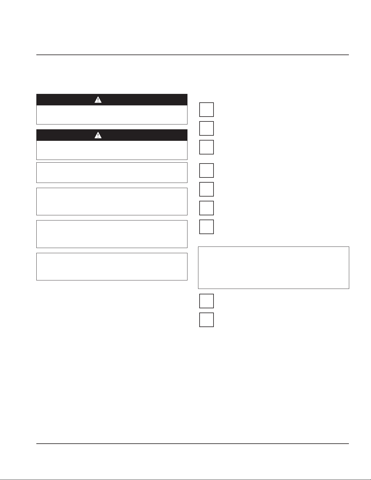
DANGER
Use appropriate safety equipment during installation
and servicing.
DANGER
Installation must comply with all applicable fire and
health codes in your jurisdiction.
Warning
n
Remove all removable panels before lifting and installing.
Warning
n
Do not damage the refrigeration circuit when installing,
maintaining or servicing the unit.
PREINSTALLATION CHECKLIST
Any damage should be noted and reported to the
delivering carrier immediately.
Check the lower portion of the unit to be sure
casters are not bent.
Visually inspect the refrigeration package,
compressor compartment housing. Be sure lines
are secure and base is still intact.
Inspect installation location behind the unit for
electrical outlet location and Nitrogen (N2).
Power unit up by plugging into power source.
Check for correct voltage at outlet dedicated for
the Nitrogen Beverage Dispenser.
Important
All plumbing must conform to local, state and national
codes.
Important
Failure to follow these installation guidelines may affect
warranty coverage.
Verify floor of install location is within 1/2" (1.3 cm)
of level front to back, side to side and all casters are
touching the floor.
Warning
n
The mass of this appliance will allow it to move
uncontrolled on an inclined surface. Adequate means
must be provided to prevent uncontrolled movement
at all times.
Check that internal connections are secure and did
not vibrate loose during shipment.
Installation location has proper ventilation where
unit has access to ambient air.
Part Number: 9290312 October/22/2018 11
Page 12
Installation Section 2
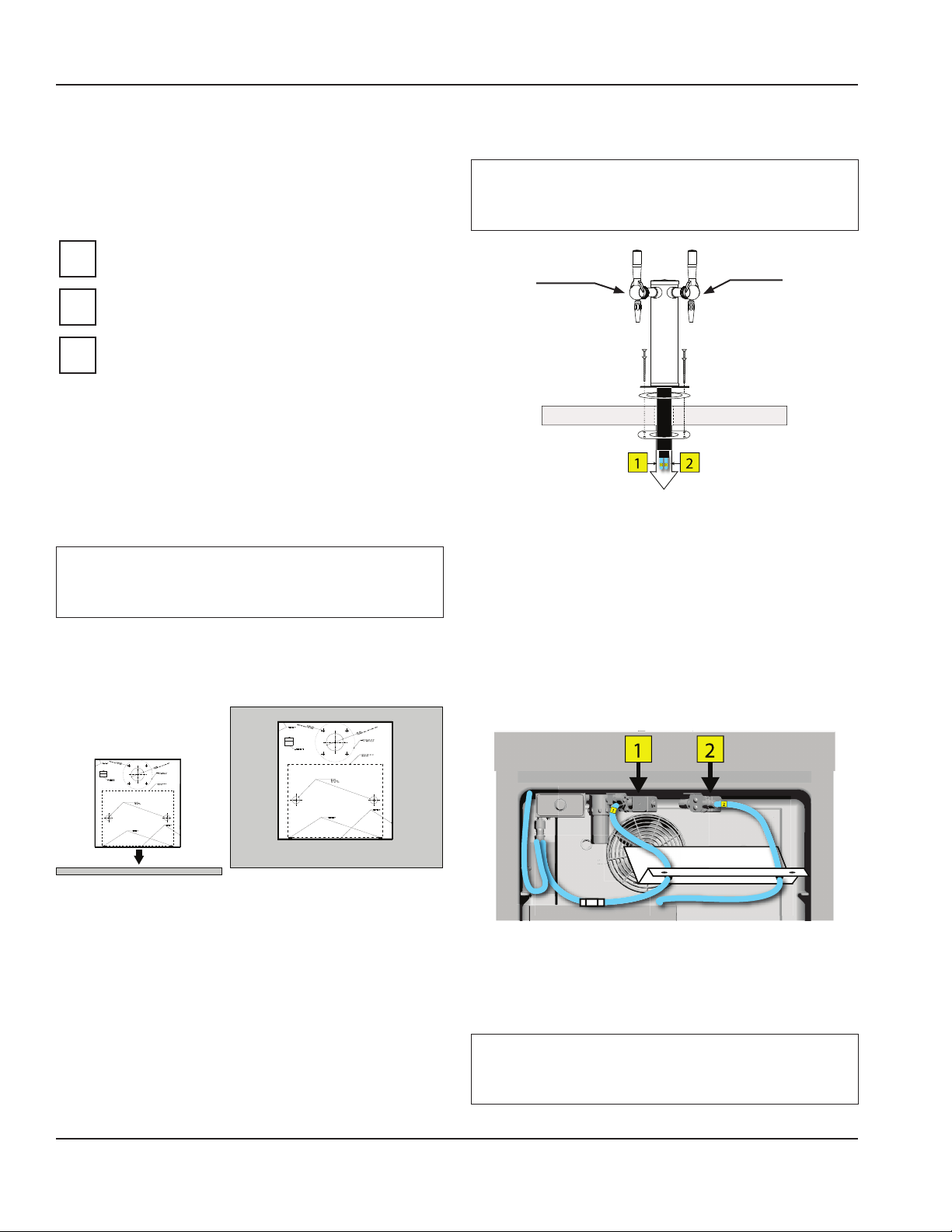
REMOTE TOWER INSTALLATION
These instructions are only for units that require remote
Mounting & Routing
placement of the dispensing tower. If this is a self contained
unit with out remote setup continue to “Nitrogen Regulator
& Tank Assembly” on page 13.
Checklist
Make sure the rubber counter top gasket is in place on
the tower before routing conduit and mounting tower.
Important
Tower location should be no more than 20.70"
(53 cm) from edge of the counter.
TAP #2
Nitro/Gas
Mount tower within 6 linear ft (1.83 m) from side of
TAP #1
Plain
base cabinet.
Make sure location has space for the drip tray
shipped with the unit.
NOTE: Drip trays equipped with a drain are also available
but are not standard equipment.
Location
1. Identify the counter top location for the tower making
To Cabinet
sure there is room for the drip tray, conduit routing
under the counter, and is away from any heat source.
Important
If the drip tray is equipped with a drain make sure install
location is near a floor drain.
2. Using the provided counter top template mark where
the 2" (5 cm) conduit and tower mount screw holes will
be drilled.
4. Route conduit from the tower down through the 2in
(5 cm) hole and mount the tower to the counter top
with the provided plate and screws.
NOTE: Make sure the rubber gasket is properly seated on
the tower and seals to the counter top.
5. Run the conduit from the tower to the N2Fusion™ cabinet.
6. Remove the two (2) screws from the solenoid cover
mounted to the inside top of the cabinet to gain access
to solenoids 1 and 2.
3. Cut and drill holes in the counter using the markings.
NOTE: Drip trays equipped with a drain will need a 7/8"
(2.22 cm) hole drilled into the counter using the provided
template for routing to a floor drain.
7. Route tubing through the top of the cabinet and attach
to the corresponding solenoids.
NOTE: Tubing already routed to the solenoids in the cabinet
should be marked with yellow 1 & 2 stickers.
Warning
n
Do not add line to the conduit this can cause poor drink
quality and the unit may not perform properly.
12 Part Number: 9290312 October/22/2018
Page 13

Section 2 Installation
C
D
A
Important
Allow four (4)ft (1.22m) of tubing for a service loop to
allow the cabinet to be pulled out during service and
cleaning. Cut off extra tubing if needed.
8. Once connections have been made put the solenoid
cover back into place.
Drip tray
9. Place drip tray or drain pan in proper location lined up
below the dispensing taps.
Important
Drip trays equipped with a drain need to be sealed to
the counter top, be sure to follow all local codes.
NITROGEN REGULATOR & TANK ASSEMBLY
DANGER
Tank under high pressure. Do not drop or allow tank to
fall over. Tank must be chained and secured to prevent
movement as per OSHA requirements. Do not attempt to
handle or connect to tank unless properly trained.
NITROGEN IS AN ASPHYXIANT GAS. A LEAK IN AN
ENCLOSED AREA COULD DISPLACE OXYGEN AND CAUSE
ASPHYXIATION. ALWAYS TEST GAS HANDLING SYSTEMS
FOR LEAKS. A N2 GAS DETECTOR IS RECOMMENDED.
Nitrogen cylinders contain high-pressure gas which can
be hazardous if not handled properly. Make sure you READ
and UNDERSTAND the following procedures for nitrogen
cylinders BEFORE installation.
6. ALWAYS check the D.O.T. test date on the cylinder neck
before installation. Ask your gas supplier for D.O.T. test
requirements.
7. NEVER connect a product container unless there is
a safety in the pressure system at or on the nitrogen
regulator.
NITROGEN INSTALLATION/REPLACEMENT
NOTE: During initial installation of the unit a bracket for the
nitrogen cylinder must be installed to solid wall nearby and
a chain used to secure it to the bracket.
Warning
n
Verify gauge orientation
before setting pressures!
B
E
NITROGEN
NITROGEN
TO PRODUCT
CONTAINER
INTEGRAL SAFETY
DEVICE
Important
Use only food grade nitrogen (99.5% pure).
1. ALWAYS connect the nitrogen cylinder to the primary
regulator and NEVER directly to the unit, keg, or
dispensing system. Failure to do so could result in
an explosion with possible death or injury when the
cylinder valve is opened.
2. ALWAYS follow correct procedures when cylinders are
changed.
3. ALWAYS secure the cylinder in an upright position with
a chain.
4. NEVER drop or throw a nitrogen cylinder.
5. ALWAYS keep a nitrogen cylinder away from heat.
1. Make sure cylinder valve “A” is closed.
2. Unscrew (counter clockwise) regulator key “B” as far out
as it will go. (The regulator is now in the off position.)
3. Remove regulator from empty cylinder at “D”.
4. Remove dust cap from new cylinder at “D”. Open and
close valve “A” quickly to blow dust from outlet.
5. With cylinder valve “A” in closed position, re-attach
regulator to cylinder at “D”.
6. Open valve “A” all the way. (This is important because
this cylinder valve seals in two places.)
7. Screw regulator key “B” in (clockwise) until required
pressure is reached “E”.
NOTE: Drinks will not pour if outlet valve “A” is closed.
Store extra cylinders in a cool place (preferably 70°F).
Securely fasten with a chain in an upright position
when storing.
Part Number: 9290312 October/22/2018 13
Page 14
Installation Section 2
NITROGEN CONNECTIONS & PRESSURES
1. Set inlet from food grade nitrogen tank to back of the
dispenser to 85 - 90 psi
(.586 - .621 MPa, 586 - 621 kPa, 5.86 - 6.21 bar).
Line OUT
Pressure to Unit
Line IN
N Tank Pressure
Warning
n
Line Out Pressure
Do Not exceed 90 psi
(.621 MPa, 621 kPa, 6.21 bar)
to the unit!
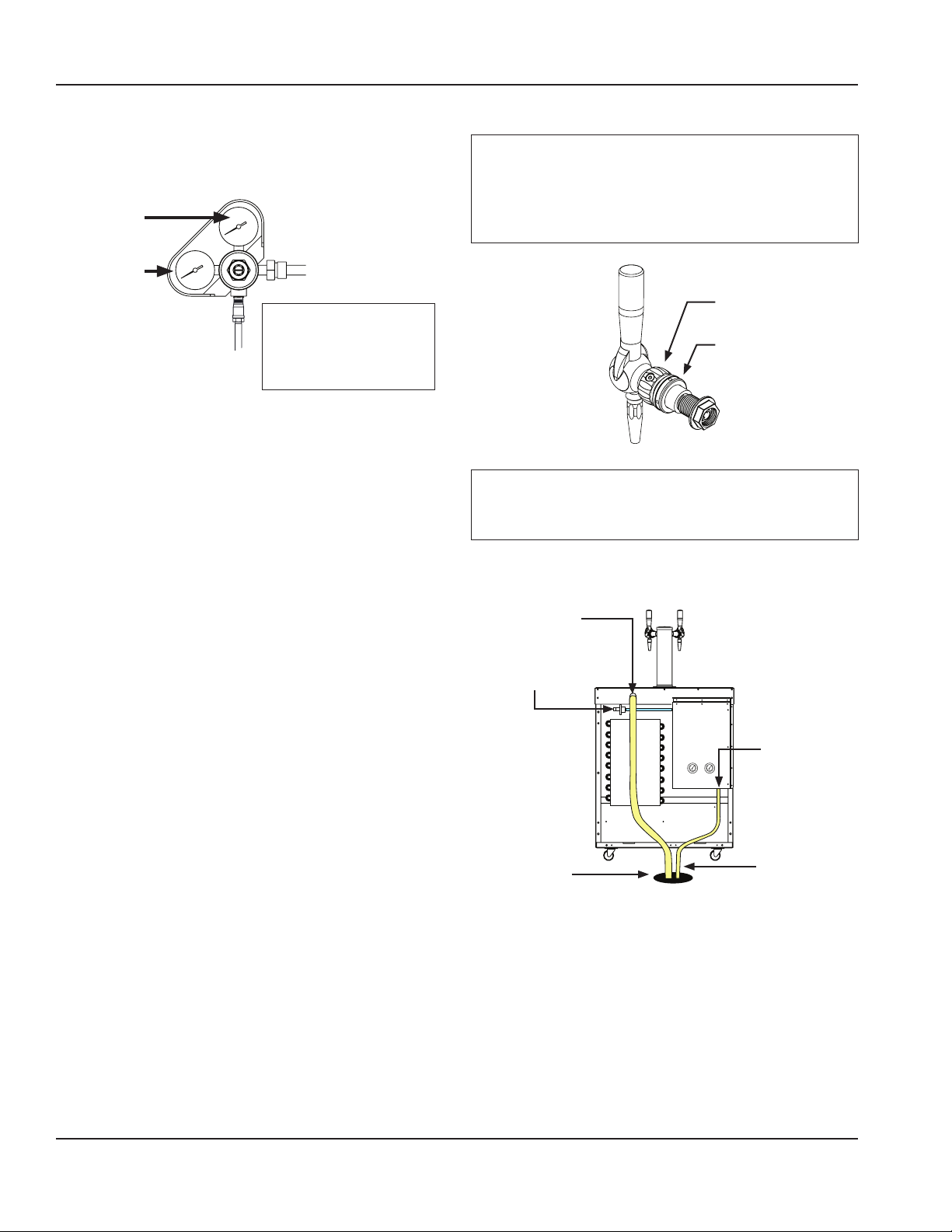
N2 QUICK DISCONNECT & DRAIN
Caution
,
Installer should always check the locking collars on the
taps are tight prior to connecting the Nitrogen supply
line. If these collars are loose they can leak at the tower
shank when pressurized.
Flow
Control
Locking
Collar
Important
All plumbing must conform to local, state and national
codes.
2. Hook up nitrogen supply line to quick disconnect.
3. Run drip pan drain line and purge tube to floor drain.
Drain Line
N2 Supply
Connection
N2 Purge Tube
Floor Drain
2" Air Gap
NOTE: Purge tube releases under pressure, make sure it is
fastened down.
4. Ensure drain line is not kinked or otherwise blocked for
proper drainage.
14 Part Number: 9290312 October/22/2018
Page 15

Section 2 Installation
KEG & PUMP REGULATORS
5. Once the nitrogen line is hooked up to the unit check the
pressures on the two (2) regulators located in the back of
the unit.
Regulator 1
Keg
Regulator 2
Nitrogenator
For 60Hz machines
6. Verify or set Regulator 1- Nitrogen Supply to Coffee Keg.
• Set to 16 psi +/- 2 psi
(.110 MPa, 110 kPa, 1.10 bar).
7. Verify or set Regulator 2- Nitrogen Supply to Nitrogenator.
• Set to 34 psi +/- 2 psi
(.234 MPa, 234 kPa, 2.34 bar).
For 50Hz machines
8. Verify or set Regulator 1- Nitrogen Supply to Coffee Keg.
• Set to 22 psi +/- 2 psi
(.152 MPa, 152 kPa, 1.52 bar).
9. Verify or set Regulator 2- Nitrogen Supply to Nitrogenator.
• Set to 44 psi +/- 2 psi
(.303 MPa, 303 kPa, 3.03 bar).
If adjustments are needed the installer or technician will
need to remove the rear cover to access the regulators.
KEG CONNECTIONS
DANGER
Never stand directly over keg when connecting,
disconnecting, or when keg is pressurized.
Important
Only use AEB Kegs. Available from Manitowoc
FoodService.
Keg Post Collars
1. Locate post collars and match the black to OUT post
and gray to IN post.
Gray collar on
IN connection
of each keg
NOTE: Color coding allows partners to match the black
connector to black collar and gray connector to gray collar.
2. Press each collar over the IN and OUT posts until they
seat in the grove below the taper.
Black collar on
OUT connection
of each keg
DANGER
ELECTRICAL SHOCK HAZARD! The power supply is
located in the upper right behind the cover and has live
heat sinks. Unplug from power source when removing
cover.
Part Number: 9290312 October/22/2018 15
Collar Groove
Page 16

Installation Section 2
Connecting the Keg
DANGER
Never stand directly over keg when connecting,
disconnecting, or when keg is pressurized.
Important
Only use AEB Kegs. Available from Manitowoc
Foodservice.
3. First connect the Black quick connect line to the
connection labeled OUT on the coffee keg. This
supplies coffee to Tap 1 and 2.
Important
Hook the OUT line up to the coffee keg first, this helps prime
the system once the nitrogen IN line is connected to the tank.
Pull ring
while
connecting
to post then
release to
lock into
place.
7. The pump may run for up to twenty (20) seconds while
priming.
NOTE: If priming fails to complete the system will go into
an error state and the Prime/Clean button LED will blink
continuously until the error is cleared. See “Clearing Error
Code” on page 20
8. Once the system is primed it is ready to pour drinks.
9. Check the regulators to make sure the pressures have
not changed and pour a few drinks from each tap to
verify proper flow. Adjust pressures if needed.
10. Check for leaks inside the cabinet and at the taps.
11. Close cabinet door and unit is ready for use.
4. Connect the Gray quick connect line second to the
connection labeled IN on the coffee keg. This line
supplies Nitrogen into tank. See “Keg Change” on page
21 & “Priming the System” on page 20
5. The system is now ready to be primed.
6. Press the Prime/Clean button, located in the upper left
corner of the refrigeration cabinet, once to prime the
coffee line. The LED around the button will flash ON
once, then OFF signifying that the Prime function has
been activated.
16 Part Number: 9290312 October/22/2018
Page 17

Section 2 Installation
PLUMBING DIAGRAM
TAP 2
NITRO
COFFEE
TAP 1
PLAIN
COFFEE
DEVICE
SENSOR
LDD
FILTER/STRAINER
PLAIN CHILLED COFFEE
VALVE
SOLENOID
PLAIN CHILLED COFFEE TO TAP 1
VALVE
SOLENOID
PUMP
COFFEE TO
PLAIN CHILLED
NITROGENATOR
LIQUID
DETECTION
KEG
16 psi +/- 2
REGULATOR 1 *
TO TAP 2
N SUPPLY TO COFFEE KEG
(.110 MPa, 110 kPa, 1.10 bar)
REGULATOR 2 **
N SUPPLY TO
NITROGENATOR
34 psi +/- 2
(.234 MPa, 234 kPa, 2.34 bar)
COFFEE OUT
NITROGENATED
N
TANK
NITROGENATOR
PRESSURE
SWITCH
PRV
DRAIN
** Regulator 2 on 50Hz Units
44 psi +/- 2 psi
* Regulator 1 on 50Hz Units
22 psi +/- 2 psi
(.303 MPa, 303 kPa, 3.03 bar)
(.152 MPa, 152 kPa, 1.52 bar)
PRIMARY REGULATOR
85-90 psi
(.586 - .621 MPa, 586 - 621 kPa, 5.86 - 6.21 bar)
SUPPLY TANK
DO NOT EXCEED 90 PSI (621 MPa, 621 kPa, 6.21 bar)
REGULATOR
PRESSURE RELIEF VALVE
NITROGEN
COFFEE
NITRO COFFEE
N
TANK
SUPPLY
Part Number: 9290312 October/22/2018 17
Page 18

Installation Section 2
DOOR HINGE REVERSAL
Instructions for installations that require the cabinet door to
be reversed.
1. Use a screwdriver to remove the bottom hinge pin.
NOTE: Lock-tight was used during factory installation, so
extra force may be required.
2. Tilt door out from bottom and slide top pin out of the
hinge bracket.
3. Remove top hinge pin from door.
4. Use a putty knife or similar tool to remove both plugs
from door to expose alternate hinge pin locations and
re-install the plugs in original hinge pin locations.
5. Install top hinge pin on new hinge side.
6. Remove top and bottom hinge brackets from cabinet
face.
7. Locate etch marks on the opposite side of cabinet face
and drill 1/8" (0.3175 cm) holes.
8. Install top and bottom hinge brackets in new locations.
9. Slide top door hinge pin into top hinge bracket and
close door onto cabinet face.
10. Install bottom hinge pin through hinge bracket and
into door.
18 Part Number: 9290312 October/22/2018
Page 19

Machine Operation
Section 3
Operation
CONTROLS/PROGRAMMING/SETTINGS
After the unit is connected to power it will automatically
begin operating. With the doors closed, the temperature of
the cabinet should reach 36°F to 40°F (2°C to 4°C) in about
one hour.
A thermostat located in the evaporator housing on interior
rear of the unit, controls the temperature in the unit. The
factory setting for the control is 4 and maintains about 38°F
(3°C) in the box. Set toward 1 for higher temperatures and
toward 7 for lower temperatures.
Refrigerators defrost automatically with every cycle of the
compressor. The water generated is routed to a pan on the
rear of the unit and is evaporated by the heat given off by
the compressor.
NOTE: During normal operation the evaporator fan may
cycle and/or pulse independently of the compressor.
PRIME / CLEAN BUTTON
The Prime/Clean button is located in the upper left corner
of the refrigeration cabinet. This button is used for priming
the system with coffee, cleaning, and displaying error codes
using the blue LED ring around the button.
The following table lists the Prime/Clean Button functions
and state the LED is in during each mode.
PRIME /CLEAN BUTTON FUNCTIONS
Mode LED
Dispense
and/or Keg
Change
Prime Blinks once then OFF when button is pressed
Cleaning ON constant after button pressed and held
Error Blinks constantly
NOTE: Error mode can be caused by the following;
A. Keg Needs Primed or Failed to Prime
B. Keg is Empty
OFF
Important
DO NOT put unit into cleaning mode with coffee keg
connected! This empty the keg and pump coffee down
the drain!
NOTE: If cleaning mode is accidentally entered with a coffee
keg attached immediately press and hold the Prime/Clean
button until the LED turns OFF. Priming may be required to
put the unit back into dispense mode.
Part Number: 9290312 October/22/2018 19
Page 20

Operation Section 3
CLEARING ERROR CODE
Important
Prime/Clean button LED will blink continuously and unit
will not dispense until the error is cleared.
To clear the error;
1. Press and hold the Prime/Clean button until the LED
around the button turns OFF.
2. Once the error has been cleared, press and release the
Prime/Clean button again to prime the unit.
PRIMING THE SYSTEM
Important
Priming is always required during keg change.
1. Press the Prime/Clean button, located in the upper left
corner of the refrigeration cabinet, once to prime the
coffee line. The LED around the button will flash ON
once, then OFF signifying that the Prime function has
been activated.
TAPS & NOZZLES
For best performance do not allow both taps to remain fully
opened for extended periods of time.
TAP #1
Surface
Important
TAP #2 Contains an o-ring,
diffuser disc, and diffuser.
TAP #2
• Tap 1 - Regular Coffee
• Tap 2 - Nitrogenated Coffee
Important
Coffee on tap 2 will not be nitrogenated properly if the
correct nozzle with diffuser is not installed.
“How to Remove Nozzles” on page 26 & “How to Install
Nozzles” on page 26
2. The pump may run for up to twenty (20) seconds while
priming.
Important
If priming fails to complete the system will go into an
error state and the Prime/Clean button LED will blink
continuously until the error is cleared.
NOTE: If error occurs See “Clearing Error Code” on page 20
3. Once the system is primed it is ready to pour drinks.
4. Close cabinet door and unit is ready for use.
Flow Control & Locking Collar
DO NOT adjust the flow control, it is set at the factory.
The locking collar keeps the tap tightened to the tower. A
special tool is required for proper adjustment.
Flow
Control
Locking
Collar
20 Part Number: 9290312 October/22/2018
Page 21

Section 3 Operation
KEGS
Important
Only use AEB Kegs. Available from Manitowoc
FoodService.
Pressure
Relief Valve
IN Post
(Gray
Nitrogen
Connector)
Warning
n
Lid
OUT Post
(Black
Coffee
Connector)
Do not attempt to remove lid until all pressure has been
relieved from keg.
KEG CHANGE
When a coffee keg is empty product will no longer
dispense.
Important
Make sure new coffee keg has been chilled to the
operating temperature range of 45° - 36°F (7° - 2°C)
before use or may cause foaming in the system.
Pull ring
to relieve
pressure
3. Pull up on the pressure relief ring on top of the keg
(illustrated above) to vent the nitrogen from the keg
and the system plumbing shown above.
NOTE: Hold the ring up until the system is fully vented
(hissing gas stops).
4. Disconnect the COFFEE OUT (black) fitting from the keg
and remove the keg.
5. Place new keg in cabinet
6. Connect the COFFEE OUT (black) fitting to the keg first
then connect the GAS IN (gray) fitting.
7. Prime system by pressing the Prime/Clean button. See
“Priming the System” on page 20
8. Pour a drink out of each tap to see if beverage comes
out, if not See “Troubleshooting Charts” on page 37.
DANGER
Never stand directly over keg when connecting,
disconnecting, or when keg is pressurized.
1. Disconnect the GAS IN (gray) fitting from the keg by
pulling up on the ring around the connector to release
from the post.
Pull up on
ring around
connector
to release.
2. Leave the COFFEE OUT (black) fitting connected to the
keg.
Part Number: 9290312 October/22/2018 21
Page 22

Operation Section 3
NITROGENATOR
Nitrogen tank is equipped with a pressure relief valve that
will automatically purge when pressure exceeds operating
limit of the system of 100 psi (.689 MPa, 689 kPa, 6.89 bar).
When valve relieves there may be a quick pressure relief
sound heard coming from cabinet. Relief sound shouldn’t
last more than a few seconds and may not be noticeable on
an audible level.
Liquid Inlet
(3/8" Flare)
N₂ Inlet
(1/4" Flare)
Common Probe
Low Probe
(Black)
(White)
High Probe
(Red)
Liquid Outlet
(3/8" Flare)
PRV Pressure
Relief Valve
(1/4" Barb)
22 Part Number: 9290312 October/22/2018
Page 23

Cleaning & Sanitizing
Section 4
Maintenance
NOTE: Cleaning items, other than the nozzle cleaning hoses,
are not supplied with the N2Fusion™ Nitrogen Beverage
Dispenser.
DANGER
It is the responsibility of the equipment owner to
perform a Personal Protective Equipment Hazard
Assessment to ensure adequate protection during
maintenance procedures.
DANGER
Failure to disconnect the power at the main power
supply disconnect could result in serious injury or death.
The power switch DOES NOT disconnect all incoming
power.
DANGER
Disconnect electric power at the main power disconnect
for all equipment being serviced. Observe correct
polarity of incoming line voltage. Incorrect polarity can
lead to erratic operation.
Important
When cleaning interior and exterior of unit, care should
be taken to avoid electrical components and wiring.
Keep water and/or cleaning solutions away from these
parts.
Warning
n
Do not damage the refrigeration circuit when installing,
maintaining or servicing the unit.
Warning
n
Never Use Steel Pads, Wire Brushes or Scrapers!
Important
Never use a high-pressure water jet for cleaning or hose
down or flood interior or exterior of units with water. Do
not use power cleaning equipment, steel wool, scrapers
or wire brushes on stainless steel or painted surfaces.
MAINTENANCE SCHEDULE
Maintenance At
Start-up
Kegs X X
Interior X X X
Gasket
Exterior X X X
Drain X X X
Condenser Coil X X X
Casters X X X
Nitrogenator PRV X
NOTE: The Pressure Relief Valve (PRV) on the nitrogenator tank needs to be replaced every 5 years by a trained technician or
service agent.
Part Number: 9290312 October/22/2018 23
X X X X
Daily Weekly Monthly After Prolonged
Shutdown
Every 5 Years
Page 24

Maintenance Section 4
GENERAL CLEANING
Interior Cleaning
Notice
When cleaning interior and exterior of unit, care should
be taken to avoid the rear power cord. Keep water and/or
cleaning solutions away from electrical parts.
Important
Never use a high-pressure water jet for cleaning or hose
down or flood interior or exterior of units with water. Do
not use power cleaning equipment, steel wool, scrapers
or wire brushes on stainless steel or painted surfaces.
The interior can be cleaned using soap and warm water. If
this isn’t sufficient, try ammonia and water or a nonabrasive
liquid cleaner.
Exterior Cleaning
Caution
,
Never use an acid-based cleaning solution! Many food
products have an acidic content, which can deteriorate
the finish. Be sure to clean the stainless steel surfaces of
ALL food products.
Clean the area around the unit as often as necessary to
maintain cleanliness and efficient operation.
Wipe gasket and surfaces with a damp cloth rinsed in water
to remove dust and dirt from the outside of the unit. Always
rub with the “grain” of the stainless steel to avoid marring
the finish. If a greasy residue persists, use a damp cloth
rinsed in a mild dish soap and water solution. Wipe dry with
a clean, soft cloth.
Never use steel wool or abrasive pads for cleaning. Never
use chlorinated, citrus based or abrasive cleaners.
Stainless steel exterior panels have a clear coating that
is stain resistant and easy to clean. Products containing
abrasives will damage the coating and scratch the panels.
Daily cleaning may be followed by an application of
stainless steel cleaner which will eliminate water spotting
and fingerprints. Early signs of stainless steel breakdown
are small pits and cracks. If this has begun, clean thoroughly
and start to apply stainless steel cleaners in attempt to
restore the steel.
CLEANING SUPPLIES
1. Gather an approved cleaner and sanitizer.
• Only use approved cleaners and sanitizers.
APPROVED CLEANERS
• Urnex® Cafiza® Espresso Machine Cleaner mixed
one (1) teaspoon per gallon, must be used. This
cleaner is compatible with equipment metals
and materials.
• KAY-5® Sanitizer/Cleaner mixed one (1) packet in
2.5 gallons (9.5L) of lukewarm water to equal 100
ppm chlorine. This is also used for the single step
weekly cleaning page 29
APPROVED SANITIZERS
• KAY-5® Sanitizer/Cleaner mixed one (1) packet in
2.5 gallons (9.5L) of lukewarm water to equal 100
ppm chlorine. This is also used for the single step
weekly cleaning page 29
• Quat based Urnex® Complete Cafe’™ mixed 1/2
oz per gallon providing 400 ppm. Used in 3 step
weekly cleaning page 31
Warning
n
Powdered cleaners and sanitizers must be thoroughly
mixed into water/solution to prevent crystals from
remaining and causing damage to system components.
2. Three (3) clean and sanitized three (3) gallon (11.36L)
pressure kegs.
• One (1) for cleaning solution.
• Two (2) for sanitizing solution.
NOTE: Only 1 keg will be needed during single step weekly
cleaning page 29
Important
Kegs used for cleaning, sanitizing solutions and rinse
water should be emptied and cleaned before reuse.
24 Part Number: 9290312 October/22/2018
Page 25

Section 4 Maintenance
3. Towels, wipes, brushes, and buckets.
• Use clean towels for any spilled fluid during
cleaning process.
• Small cleaning wipes for cleaning top, sides, and
interior of unit.
• A small brush is useful to clean keg connections
• Small bucket should be available for dipping
keg connections into sanitizer.
4. Spray bottles and PPE (gloves, goggles).
MANUAL KEG CLEANING
This is to be performed when a product keg is empty prior
to filling the keg with new product.
1. Empty remaining product from the keg into the
3-compartment sink.
2. Add QSR Heavy Duty Multi-Purpose Sink Detergent™
from the dispenser at the back room sink, or other
approved cleaning solution mixed to the proper
concentration, with warm tap water in the keg.
3. Use the urn brush to scrub the inside of the keg and lid,
loosening coffee soils, oils, and residue.
4. Empty the dirty soapy water into the 3-compartment sink.
NOTE: Take care not to damage the inner parts of the keg
including the stem.
Warning
n
When in contact with cleaning and sanitizing solution
chemicals gloves and safety glasses are recommended.
• Use spray bottle when wiping down surfaces
and other exterior parts.
• Gloves and eye protection should be worn to
lessen chance of irritation or injury.
5. Fill half the keg with clean water, replace the lid, and
agitate the keg to thoroughly rinse the inside of the keg.
6. Empty the rinse water into the 3-compartment sink.
7. Mix proper concentration of approved sanitizing
solution (400 ppm Quat concentrate) in the keg with
warm tap water.
8. Replace the lid and agitate the keg to thoroughly
sanitize the inside of the keg.
9. Allow the sanitizer to sit inside of the keg for at least
one minute.
10. Empty the sanitizer solution into the 3-compartment sink.
11. Store the keg and lid in a location that protects the keg
from overhead contamination.
12. Allow the keg and lid to fully air dry before next use.
Part Number: 9290312 October/22/2018 25
Page 26

Maintenance Section 4
LEVEL 1 DAILY CLEANING
Cleaning
1. Put on gloves and safety goggles before cleaning unit.
2. Spray each tap with cleaner, wipe down, look for
obstructions, and check for proper flow.
Sanitizing
1. Add approved sanitizer to spray bottle mixed to
appropriate ppm concentration and spray all external
surfaces. Allow to remain for 15 minutes, or as directed
by manufacturer, before wiping off.
Spray with
cleaner and
wipe
Remove &
wash in sink
TAP #1
Surface
TAP #2
Important
TAP #2 Contains an o-ring,
diffuser disc, and diffuser.
3. Drain gate should be removed, interior of drain pan
cleaned, and wiped dry.
4. Wash drain gate in sink and allow to dry.
5. Spray top surface of unit with cleaner and wipe dry.
6. Check interior for any spills or drips, spray with cleaner
and wipe down.
DO NOT Spray
Electronic
Components!
Wipe down
interior surfaces
and any spills
Caution
,
Attention and care should be used to avoid spraying
any electrical component (fans, thermostat and sensor
connections) with any of the fluids.
2. Spray each nozzle and allow to air soak for 15 minutes,
or as directed by manufacturer, before wiping off.
NOTE: If removing tap nozzles to clean/sanitize, tap 2
contains an o-ring and diffuser. DO NOT lose the diffuser and
make sure it is put back on tap 2 after cleaning/sanitizing.
HOW TO REMOVE NOZZLES
A. Rotate nozzle counter-clockwise by hand, no tool
should be required for removal.
NOTE: Be aware of the diffuser and o-ring in the tap 2 nitro
nozzle. If they are taken out of the nozzle replace in the
correct order as illustrated above.
HOW TO INSTALL NOZZLES
A. To re-install the nozzle, thread the nozzle back
onto the tap by turning clockwise and firmly
hand tighten to prevent leaks, no tool required for
installation.
Important
Coffee on tap 2 will not be nitrogenized properly if the
correct nozzle with diffuser are not installed.
3. Spray internal surfaces and allow to air soak for 15 minutes,
or as directed by manufacturer, before wiping off.
Caution
7. Pull unit out and clean around the cabinet.
,
Attention and care should be used to avoid spraying
any electrical component (fans, thermostat and sensor
connections) with any of the fluids.
26 Part Number: 9290312 October/22/2018
Page 27

Section 4 Maintenance
Rinsing
Wipe down each nozzle with wet clean towel and allow to
air dry. If Keg was disconnected and cleaned/sanitized, wipe
down connectors with clean wet towel and allow to air dry.
Clean In-line Strainer
1. Locate the in-line coffee strainer on the celling of the
refrigeration cabinet.
Bowl
HOW TO REMOVE STRAINER
A. First depressurize the system and disconnect the
keg. See “Keg Change” on page 21
B. Put down a towel or small cloth to catch any coffee
that may still be in the line or bowl during removal.
C. Grasp the bowl and rotate counterclockwise to
loosen and remove the bowl.
Strainer
Gasket
Bowl
NOTE: The strainer is a metal mesh ring that will be located
inside the bowl. Also be careful not to damage the rubber
gasket that is seated in the bowl.
D. Visually inspect the clear strainer bowl for debris
and coffee grinds.
E. Rinse under tap water, scrub thoroughly inside and
out with the tube brush included with the unit.
F. Clean and sanitize before putting back into place.
G. Reassemble the bowl with mesh and gasket back in place.
H. Rotate bowl clockwise and hand tighten.
I. Reconnect the keg and check for leaks.
Important
Strainer should be cleaned at minimum once a day.
Part Number: 9290312 October/22/2018 27
Page 28

Maintenance Section 4
THIS PAGE INTENTIONALLY LEFT BLANK
28 Part Number: 9290312 October/22/2018
Page 29

Section 4 Maintenance
LEVEL 2 WEEKLY CLEANING SINGLE STEP METHOD
Important
One of the Level 2 methods is to be performed daily on
the Milk line.
NOTE: Only to be performed using KAY-5® Sanitizer/Cleaner,
if KAY-5® Sanitizer/Cleaner is not available the three step,
Clean, Rinse, Sanitize method must be performed. See “Level 2 -
Weekly Cleaning (Three Step Method)” on page 31
1. Approved Sanitizer / Cleaner.
APPROVED CLEANER/SANITIZER
• KAY-5® Sanitizer/Cleaner mixed one (1) packet in
2.5 gallons (9.5L) of lukewarm water to equal 100
ppm chlorine. This sanitizer / cleaner is compatible
with equipment metals and materials.
NOTE: The cleaner / sanitizer must provide 100 ppm chlorine,
use the provided 2.5 (9.5L) measuring bucket to ensure
proper ratio.
Warning
n
Powdered cleaners and sanitizers must be thoroughly
mixed into water/solution to prevent crystals from
remaining and causing damage to system components.
Make sure one (1) properly cleaned and sanitized cleaning
keg is available to perform proper weekly cleaning. See
“Manual Keg Cleaning” on page 25 & “Level 3 - Monthly
Cleaning” on page 34
Coffee Delivery System Cleaning & Sanitizing
1. Disconnect coffee keg and set aside.
Clean In-line Strainer
2. De-pressurize the system. See “Keg Change” on page
21 then See “Clean In-line Strainer” on page 27.
Bowl
3. Reassemble the bowl with mesh and gasket back in place.
Cleaning the System
4. Mix proper concentration of KAY-5® Sanitizer/Cleaner
solution in the three (3) gallon cleaning keg with warm
tap water.
5. Connect the outlet (OUT) then inlet (IN) keg connectors
cleaning solution keg.
6. Press and release the Prime/Clean button to prime
the system with cleaning/sanitizing solution. The LED
around the button will flash ON then OFF.
Cleaning
Hoses
Prime/Clean
Button
Sanitizing
Keg
5 Gallon
Bucket
7. Place a clean five (5) gallon bucket on the floor in front of unit.
8. Place clear nozzle cleaning hose over nozzles of both the
(plain and nitrogen coffee) taps and place other end of clear
hoses in the five (5) gallon bucket.
9. Open both the plain and nitrogen coffee taps.
10. Press and hold the Prime/Clean button until the LED around
the button turns on to place the unit into cleaning mode.
NOTE: Cleaning button will illuminate blue in color around the
button indicating unit is in cleaning mode.
Part Number: 9290312 October/22/2018 29
Page 30

Maintenance Section 4
11. Unit will automatically run through the cleaning/
sanitizing process.
12. Towards the end of cleaning /sanitizing process there will
be a system purge process and once bubbles are seen
coming from five (5) gallon bucket, close plain coffee tap.
13. Once cleaning /sanitizing process is complete the LED
will not be illuminated, which indicates cleaning is
complete and both product taps can now be closed.
NOTE: To abort cleaning mode at any time press and hold
the cleaning button until the LED around the Prime/Clean
button turns OFF. This exits cleaning mode into keg change
mode and LED will no longer be illuminated.
NOTE: Priming is required after aborting cleaning or
clearing an error. See “Priming the System” on page 20
Important
If cleaning mode is accidentally aborted or aborted because
of an issue/reason, then the cleaning process will need to
start over from the beginning after a two (2) minute wait.
NOTE: If an error is encountered at any time during cleaning
process the cleaning button will blink ON/OFF rapidly
indicating unit is in an error state and cleaning process has
stopped. See “Clearing Error Code” on page 20.
14. Disconnect cleaning keg and set aside.
15. Disconnect clear drain hoses from tap nozzles, empty
five (5) gallon bucket and store for use during next
weekly cleaning.
Important
Kegs used for cleaning & sanitizing solutions should be
emptied and cleaned before reuse.
Clean In-line Strainer
16. Once the cleaning/sanitizing is complete the strainer
will need cleaned again to ensure no new debris have
been trapped in the filter.
17. De-pressurize the system. See “Keg Change” on page
21 then See “Clean In-line Strainer” on page 27.
18. Reassemble the bowl with mesh and gasket back in place.
19. Complete all other weekly cleaning tasks before
reconnecting coffee keg to unit. See “Interior/Exterior
Cleaning, Sanitizing & Rinse” on page 34, and See “Keg
Connector Cleaning” on page 33.
30 Part Number: 9290312 October/22/2018
Page 31

Section 4 Maintenance
LEVEL 2 WEEKLY CLEANING THREE STEP METHOD
1. Approved cleaner and sanitizer.
• Only use approved cleaners and sanitizers.
APPROVED CLEANERS
• Urnex® Cafiza® Espresso Machine Cleaner mixed
one (1) teaspoon per gallon, must be used. This
cleaner is compatible with equipment metals
and materials.
• KAY-5® Sanitizer/Cleaner mixed one (1) packet in
2.5 gallons (9.5L) of lukewarm water to equal 100
ppm chlorine.
APPROVED SANITIZERS
• KAY-5® Sanitizer/Cleaner mixed one (1) packet in
2.5 gallons (9.5L) of lukewarm water to equal 100
ppm chlorine.
• Quat based Urnex® Complete Cafe’™ mixed 1/2
oz per gallon providing 400 ppm. Used in 3 step
weekly cleaning page 31
Make sure three (3) properly cleaned and sanitized cleaning
kegs are available to perform proper weekly cleaning. See
“Manual Keg Cleaning” on page 25 & “Level 3 - Monthly
Cleaning” on page 34
Coffee Delivery System Cleaning & Sanitizing
1. Disconnect coffee keg and set aside.
Clean In-line Strainer
2. De-pressurize the system. See “Keg Change” on page
21 then See “Clean In-line Strainer” on page 27.
Bowl
3. Reassemble the bowl with mesh and gasket back in place.
Cleaning the System
4. Mix proper concentration of cleaning solution in one of
the three (3) gallon kegs with warm tap water.
5. Connect the outlet (OUT) then inlet (IN) keg connectors
cleaning solution keg.
6. Press and release the Prime/Clean button to prime the
system with cleaning solution. The LED around the
button will flash ON then OFF.
Cleaning
Hoses
Prime/Clean
Button
Cleaning
Keg
5 Gallon
Bucket
7. Place a clean five (5) gallon bucket on the floor in front of unit.
8. Place clear nozzle cleaning hose over nozzles of both
the (plain and nitrogen coffee) taps and place other
end of clear hoses in the five (5) gallon bucket.
9. Open both the plain and nitrogen coffee taps.
10. Press and hold the Prime/Clean button until the LED
around the button turns on to place the unit into
cleaning mode.
NOTE: Cleaning button will illuminate blue in color around
the button indicating unit is in cleaning mode.
11. Unit will automatically run through the cleaning process.
12. Towards the end of cleaning process there will be a
system purge process and once bubbles are seen coming
from five (5) gallon bucket, close plain coffee tap.
13. Once cleaning process is complete the LED will not be
illuminated, which indicates cleaning is complete and
both product taps can now be closed.
14. Empty the five (5) gallon bucket and place ends of clear
nozzle drain hoses back into bucket.
15. Disconnect cleaning solution keg and set aside, then
continue to “Rinsing & Sanitizing the System” on page 32.
NOTE: To abort cleaning mode at any time press and hold
the cleaning button until the LED around the Prime/Clean
button turns OFF. This exits cleaning mode into keg change
mode and LED will no longer be illuminated.
Part Number: 9290312 October/22/2018 31
Page 32

Maintenance Section 4
NOTE: Priming is required after aborting cleaning or
clearing an error. See “Priming the System” on page 20
Important
If cleaning mode is accidentally aborted or aborted because
of an issue/reason, then the cleaning process will need to
start over from the beginning after a two (2) minute wait.
NOTE: If an error is encountered at any time during cleaning
process the cleaning button will blink ON/OFF rapidly
indicating unit is in an error state and cleaning process has
stopped. See “Clearing Error Code” on page 20.
Rinsing & Sanitizing the System
1. Mix proper concentration of approved sanitizing
solution (400 ppm Quat concentrate) in the second
three (3) gallon keg with warm tap water.
NOTE: If this is the second time sanitizing use the third and
final three (3) gallon keg.
2. Connect the outlet (OUT) then inlet (IN) keg connectors
of unit to sanitizing solution keg.
Cleaning
Hoses
Prime/Clean
Button
Sanitizing
Keg
5 Gallon
Bucket
7. Unit will automatically run through the cleaning process.
8. Towards the end of sanitizing process there will be a
system purge process and once bubbles are seen coming
from five (5) gallon bucket, close plain coffee tap.
9. Once sanitizing process is complete cleaning button
will not be illuminated, which indicates sanitizing is
complete and both product taps should be closed.
10. Empty the five (5) gallon bucket and place ends of clear
nozzle drain hoses back into bucket.
11. Disconnect sanitizer solution keg two (2) and set aside.
12. Repeat “Rinsing & Sanitizing the System” Step 1 through
Step 11 to completely sanitize the system before
continuing to Step 13.
13. Disconnect clear drain hoses from tap nozzles, empty
five (5) gallon bucket and store for use during next
weekly cleaning.
Important
Kegs used for cleaning & sanitizing solutions should be
emptied and cleaned before reuse.
Clean In-line Strainer
14. Once the final sanitizing is complete the strainer will
need cleaned again to ensure no new debris have been
trapped in the filter.
15. De-pressurize the system. See “Keg Change” on page
21 then See “Clean In-line Strainer” on page 27.
16. Reassemble the bowl with mesh and gasket back in
place.
17. Complete all weekly cleaning tasks before
reconnecting coffee keg to unit. See “Interior/Exterior
Cleaning, Sanitizing & Rinse” on page 34, and See “Keg
Connector Cleaning” on page 33.
3. Press and release the Prime/Clean button to prime the
system with sanitizing solution. The LED around the
button will flash ON then OFF.
4. Make sure the cleaning hoses are connected to the taps
and the other ends are in the 5 gallon bucket.
5. Open both the plain and nitrogen coffee taps.
6. Press and hold the Prime/Clean button until the LED
around the button turns on to place the unit into
cleaning mode.
NOTE: Cleaning button will illuminate blue in color around
the button indicating unit is in cleaning mode.
32 Part Number: 9290312 October/22/2018
Page 33

Section 4 Maintenance
Keg Connector Cleaning
1. If keg is not disconnected, then do so and set keg aside.
Warning
n
NEVER ATTEMPT TO REMOVE KEG LID WITHOUT FIRST
DE-PRESSURIZING KEG!
Pull ring to
release from
post
NOTE: An alternative method is to heavily spray both
of the connectors with sanitizing solution and allow
sanitizer to remain for fifteen (15) minutes or as directed by
manufacturer.
2. Once keg connectors are cleaned and sanitized each
2. Spray cleaner on one keg connector and wipe down
with clean towel.
one should be immersed into clean water for at least
five (5) minutes for rinsing.
3. If required a brush can be used for stains or residue
build-up.
4. Repeat Step 1 and 2 for other keg connectors.
Keg Connector Sanitizing
• Frequency: Every week or as required.
1. Mix proper concentration of approved sanitizing
solution in clean bucket and place keg connectors into
bucket and allow to soak for 15 minutes , or as directed
by manufacturer.
Part Number: 9290312 October/22/2018 33
Page 34

Maintenance Section 4
Interior/Exterior Cleaning, Sanitizing & Rinse
1. Put on gloves and safety goggles before cleaning unit.
2. Spray each tap with cleaner, wipe down, look for
obstructions, and check for proper flow.
3. Drain gate should be removed and interior of drain pan
cleaned and wiped dry.
4. Wash drain gate in sink and allow to dry.
5. Spray top surface of unit with cleaner and wipe dry.
6. Check interior for any spills or drips, spray with cleaner
and wipe down.
Perform the a weekly cleaning on all six (6) store kegs, three
(3) product and three (3) cleaning. This can be performed
during the weekly cleaning once a month.
DO NOT Spray
Electronic
Components!
Wipe down
interior surfaces
and any spills
Caution
,
Attention and care should be used to avoid spraying
any electrical component (fans, thermostat and sensor
connections) with any of the fluids.
Connect Keg & Prime System
Once all cleaning has been completed the keg can be
reconnected to the system.
Important
Make sure new coffee keg has been chilled to the
operating temperature range of 45° - 36°F (7° - 2°C)
before use or may cause foaming in the system.
• See “Keg Change” on page 21
• Close cabinet door and unit is ready for use.
LEVEL 3 MONTHLY CLEANING
In Place Keg Cleaning
34 Part Number: 9290312 October/22/2018
Page 35

Section 4 Maintenance
Other Operations
DOORS & HINGES
Over time and with heavy-use doors, the hinges may
become loose. If this happens, tighten the screws that
mount the hinge brackets to the frame of the unit. Loose
or sagging doors can cause the hinges to pull out of the
frame, which may damage both the doors and the hinges.
In some cases this may require qualified service agents or
maintenance personnel to perform repairs.
Door Adjustment
If the door needs lowering at the handle, use a 5/16” (8 mm)
wrench to loosen the hinge screws and install a spacer
outside of the hinge. Tighten the screws.
If the door needs to be higher at the handle, use a 5/16”
(8 mm) wrench to loosen the hinge screws and install a
spacer inside of the hinge. Tighten the screws.
Part Number: 9290312 October/22/2018 35
Page 36

Maintenance Section 4
THIS PAGE INTENTIONALLY LEFT BLANK
36 Part Number: 9290312 October/22/2018
Page 37

Section 5
Troubleshooting
Troubleshooting Charts
Prior to contacting Service please find the issue in one of the charts and perform the correction, if the issue is not listed or
persists then contact Service.
DISPENSING ISSUES
Problem Cause Correction
Coffee does not dispense Power Is there power to the unit? Plug in unit.
Product keg is empty Change out the product keg. See “Keg Change” on
page 21
Keg connectors not connected Check keg connectors. See “Keg Change” on page
21
Low / No Nitrogen pressure. Open Nitrogen tank valve, adjust pressure, or
change N2 supply tank. See “Nitrogen Installation/
Replacement” on page 13
Nitrogen supply tank is empty Change out the Nitrogen supply tank. See
“Nitrogen Installation/Replacement” on page 13
Debris in in-line strainer/filter Clean filter. See “Clean In-line Strainer” on page
31
Product line is not primed Press the Prime/Clean button for one second to
prime system
Stuck in clean cycle Is Prime/Clean LED ON , press & hold till turns
OFF
Error mode, Prime/Clean button blinking See “Clearing Error Code” on page 20
Nitrogen Supply Tank OFF Turned OFF when tank was swapped/installed. Check Nitrogen tank. See “Nitrogen Installation/
Tank incorrectly shut OFF during keg change.
The coffee seems to be watery Is the cleaning / purge light button on Finish cycle & replace the product keg. See “Keg
The coffee is warmer than expected Verify the thermometer reads below 50°F Refer to refrigeration section checklist. See
“Controls/Programming/Settings” on page 19
Coffee keeps leaking from the clear
drain hose
There is a hissing sound coming from
the nitrogen tank
There is a puddle of product on the
floor
The drain pan under the taps has
standing coffee
Product does not appear to be
nitrogenated
Product flowing slow from valve Debris in nozzle Remove nozzle and clean. See “How to Remove
Foam dispensing from valve Cold brew temp above 45 degrees Attach keg of cold brew that is chilled to below
The nitrogenator tank relief valve is stuck open Close or replace.
Regulator nut Tighten regulator nut. See “Nitrogen Regulator &
Check for missing washer inside of regulator nut.
Drain tube Check to see of cabinet drain is in the floor drain.
See “N2 Quick Disconnect & Drain” on page 33
Pinched or clogged drain line Clean out drain line.
Nitro Coffee nozzle does not have diffuser
installed
Debris in filter Remove and Clean Filter. See “Clean In-line
Check Nitro pressure gauge Make sure pressures are set correctly. See
Nitrogen pump not running Call for service
If no other cause was found, the flow control
collar on valve may be out of adjustment
Check cold brew nozzle to see if nozzles were
reversed. Nozzle with diffuser disc is intended to
be installed on the Nitro side of the tower.
“Nitrogen Connections & Pressures” on page 14
Replacement” on page 13
Change” on page 21
and “Keg Change” on page 21
Tank Assembly” on page 13
Replace drain line.
Nozzles” on page 26
Strainer” on page 27
and “Keg & Pump Regulators” on page 15
Call Service to have adjusted.
45°F. See “Keg Change” on page 21
Part Number: 9290312 October/22/2018 37
Page 38

Troubleshooting Section 5
DISPENSING ISSUES
Problem Cause Correction
Cleaning button blinking ON/OFF
rapidly
Keg connectors won’t go onto the keg
posts
Unit is in an error state and cleaning process
has stopped., keg empty.
System fails to prime.
Pump runs continuously for >5 minutes.
Incorrect connector Make sure the IN connector is gray and the OUT
Not pulling up on the connector release ring
while connecting
Hold Prime/Clean button until the LED turns
OFF. (See “Clearing Error Code” on page 20)
Replace keg if needed then press and release the
Prime/Clean button again to prime the new keg.
Cleaning process can be started over after a two
(2) minute wait.
connector is black. See “Keg Change” on page 21
Pull up on the ring around the connector to allow
it to slip over the IN or OUT post and lock into
place. See “Keg Change” on page 21
REFRIGERATOR CABINET ISSUES
Problem Cause Correction
Cabinet not running Fuse blown or circuit breaker tripped. Replace fuse or reset circuit breaker.
Power cord unplugged. Plug in power cord.
Thermostat set too high. Set thermostat to lower temperature.
Condensing unit runs for long periods
or continuously
Cabinet temperature is too high Thermostat set too high. Set thermostat to lower temperature.
Excessive amount of warm product placed in
cabinet.
Prolonged door openings or door(s) ajar. Make sure door(s) are closed when not in use.
Door gasket(s) not sealing properly. Check gasket condition. Adjust door or replace
Dirty condenser coil. Clean the condenser coil.
Evaporator coil iced over. Turn unit off and allow coil to defrost. Make
Allow adequate time for product to cool down.
Avoid prolonged door openings.
gasket if necessary.
sure thermostat is not set too cold.
Also, check gasket condition.
Poor air circulation in cabinet. Re-arrange product to allow proper air
circulation.
Excessive amount of warm product placed in
cabinet.
Prolonged door openings or door(s) ajar. Make sure door(s) are closed when not in use.
Dirty condenser coil. Clean the condenser coil.
Evaporator coil iced over. Turn unit off and allow coil to defrost. Make
Cabinet is noisy Loose part(s). Locate and tighten loose part(s).
Refrigerator is freezing product Thermostat is set too low. Set thermostat to higher temperature.
Dirty condenser coil. Clean the condenser coil.
Not enough cabinet clearance for proper
refrigeration system operation.
Compressor will not start Low voltage to cabinet. Check and correct incoming voltage to cabinet.
Leaking internally Check the in-line filter bowl and o-ring. May need to depressurize the unit and remove
Allow adequate time for product to cool down.
Avoid prolonged door openings.
sure thermostat is not set too cold.
Also, check gasket condition.
Move cabinet or make other adjustments to
gain proper cabinet clearances.
the filter bowl to check. See “How to Remove
Strainer” on page 27
38 Part Number: 9290312 October/22/2018
Page 39

Section 5 Troubleshooting
POURING
If coffee does not pour out of taps items to check are;
1. Verify connections to keg and if coffee keg is empty. If
keg is empty follow replacement steps on page 16.
2. If keg has coffee check nitrogen level at nitrogen tank.
• If outlet pressure drops below 85 - 90 PSI (.586
- .621 MPa, 586 - 621 kPa, 5.86 - 6.21 bar) or
tank volume is low replace tank and connect as
shown on page 14.
Part Number: 9290312 October/22/2018 39
Page 40

Troubleshooting Section 5
THIS PAGE INTENTIONALLY LEFT BLANK
40 Part Number: 9290312 October/22/2018
Page 41

Page 42

Page 43

Page 44

MULTIPLEX
2100 FUTURE, SELLERSBURG, IN 47172
800-367-4233
WWW.WELBILT.COM
WWW.WELBILT.COM
Welbilt provides the world’s top chefs, and premier chain operators or growing independents with industry leading equipment and solutions. Our cutting-edge
designs and lean manufacturing tactics are powered by deep knowledge, operator insights, and culinary expertise.
All of our products are backed by KitchenCare® – our aftermarket, repair, and parts service.
CLEVELAND
CONVOTHERM®
©2017 Welbilt Inc. except where explicitly stated otherwise. All rights reserved.
Part Number: 9290312 October/22/2018
DELFIELD®
FITKITCHEN™
FRYMASTER®
GARLAND
KOLPAK®
LINCOLN
MANITOWOC®
MERCO®
MERRYCHEF®
MULTIPLEX®
 Loading...