

Page 1
Multiplex Beverage Systems
Operations Manual for
Model MV2000
Beverage System
Operations Manual
Multiplex Beverage Systems
e-mail: info@multiplex-beverage.com w www.multiplex-beverage.com
In accordance with our policy of continuous product development and
improvement, this information is subject to change at any time without notice.
Multiplex Company, Inc.
250 Old Ballwin Road w St. Louis, Missouri 63021-4800
Tel: 636.256.7777 w Fax: 636.527.4313
Printed in The United States of America
EI902005
Issued August 1999
Page 2

Page 3

Multiplex Company, Inc. Beverage Systems Operations Manual
Table of Contents
English Section ...................................................................................................................... 1
Caution: To Avoid Serious Injury ................................................................................................................. 2
Introduction ................................................................................................................................................ 3
Unpacking the support stand and its components ..................................................................................... 3
Setting-up the support stand ..................................................................................................................... 3
Mounting the Standard Accessories ............................................................................................................. 4
Accumulator Tank Kit .............................................................................................................................. 4
CO2 Control Panel ................................................................................................................................... 4
Water Filter Package ................................................................................................................................ 4
CO2 Tank Bracket .................................................................................................................................... 4
Procedure for mounting the refrigeration unit to the support stand ............................................................... 5
Mounting the optional accessories............................................................................................................... 5
Water Booster Pump Assembly ................................................................................................................ 5
Air Compressor Assembly ........................................................................................................................ 6
Accessories Switch Box............................................................................................................................ 6
Procedure for connecting the water supply to the equipment package ......................................................... 7
How to connect the CO2 (Air) supply to the equipment package .................................................................. 7
Connecting the refrigeration units supply conduits ...................................................................................... 8
Routing the syrup supply conduit and connecting it to the pumps ............................................................. 8
Connecting the Recirculating Conduit ...................................................................................................... 8
Loading the Bag-In-Box Syrup Supply ....................................................................................................... 8
Starting the system up ................................................................................................................................. 8
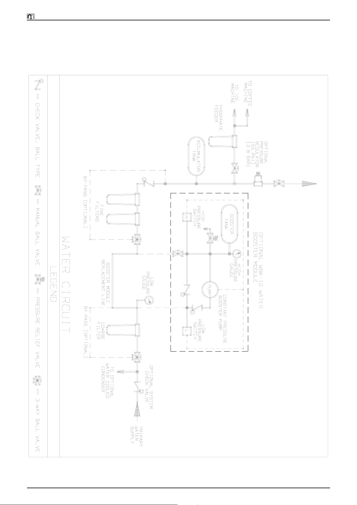
Model MV2000 Water Circuit Diagram ....................................................................................................... 9
French Section .................................................................................................................... 11
Avertissement: Pour éviter de graves accidents ......................................................................................... 12
Introduction .............................................................................................................................................. 13
Déballage du Comptoir et de ses composants......................................................................................... 13
Installation du Comptoir......................................................................................................................... 13
Montage des Accessoires Standard ............................................................................................................ 14
Kit du Réservoir dEmmagasinage........................................................................................................... 14
Panneau de Commande de CO2 ............................................................................................................. 14
Dispositif de Filtration dEau .................................................................................................................. 14
Support de Réservoir de CO2 ................................................................................................................. 14
Procédure de montage du dispositif de réfrigération sur le Comptoir .......................................................... 15
Montage des accessoires optionnels ............................................................................................. ............. 15
Groupe Pompe de Surpresseur dEau .............................................................................................. ....... 15
Groupe Compresseur dAir ....................................................................................................... ............. 16
Boîtier de Commande des Accessoires ............................................................................................ ....... 16
Procédure de raccordement de lalimentation deau à léquipement .......................................................... 17
Comment brancher lalimentation (dair) de CO2 à léquipement ............................................................... 17
Branchement des conduites dalimentation du dispositif de réfrigération .................................................... 18
Installation et raccordement aux pompes de la conduite dalimentation de sirop ..................................... 18
Branchement de la Conduite de Recirculation ........................................................................................ 18
Chargement de lalimentation en Sirop des cubitainers ...........................................................................18
Mise en route du système .......................................................................................................................... 18
Schéma de Circuit de lEau du Modèle MV2000........................................................................................ 19
EI902005 Table of Contents Issued (TFB/BT/BM/KAZ) 08/18/99
Page 4

Multiplex Company, Inc. Beverage Systems Operations Manual
Table of Contents (continued)
Italian Section ..................................................................................................................... 21
Attenzione: per evitare lesioni gravi .......................................................................................................... 22
Introduzione ............................................................................................................................................. 23
Disimballaggio del banco di supporto e dei suoi componenti ................................................................. 23
Allestimento del banco di supporto ........................................................................................................ 23
Montaggio degli accessori standard ........................................................................................................... 24
Kit di montaggio serbatoio di accumulo ................................................................................................. 24
Pannello di controllo CO2 ...................................................................................................................... 24
Unità filtrante per lacqua....................................................................................................................... 24
Supporto per serbatoio CO2 ................................................................................................................... 24
Procedura per il montaggio dellunità di refrigerazione sul banco di supporto ............................................ 25
Montaggio degli accessori supplementari .................................................................................................. 25
Gruppo pompa di sovralimentazione acqua ........................................................................................ ... 25
Gruppo compressore daria .................................................................................................................... 26
Scatola interruttori supplementari ........................................................................................................... 26
Procedura per il collegamento dalimentazione idrica allapparecchio ....................................................... 27
Come collegare lalimentazione di CO2 (aria) allapparecchio .................................................................... 27
Collegamento delle condutture di alimentazione dellunità di refrigerazione ............................................. 28
Definizione della conduttura di alimentazione dello sciroppo e suo collegamento alle pompe................ 28
Collegamento delle condutture di ricircolo............................................................................................. 28
Caricamento del rifornimento dello sciroppo alle Bag-in-Box.................................................................. 28
Avviamento del sistema ............................................................................................................................ 28
Schema idrico Modello MV2000 ............................................................................................................... 29
German Section .................................................................................................................. 31
Warnhinweise: zur Vermeidung schwerwiegender Verletzungen .............................................................. 32
Einführung ................................................................................................................................................ 33
Auspacken des Trägergestells und seiner Teile ....................................................................................... 33
Aufstellen des Trägerständers ................................................................................................................. 33
Einbau des Standard-Zubehörs................................................................................................................... 33
Tankbehälterset ..................................................................................................................................... 33
CO2 Kontrolltafel ................................................................................................................................. 34
Wasserfilterpaket ................................................................................................................................... 34
CO2 Flaschenhalter .............................................................................................................................. 34
Verfahren zum Einbau des Kühlgeräts am Trägergestell ............................................................................. 35
Einbau des wahlweisen Zubehörs.............................................................................................................. 35
Aufbau der Wasser-Druckaufbaupumpe ................................................................................................. 35
Luftkompressor ...................................................................................................................................... 36
Zubehör-Schaltkasten............................................................................................................................. 36
Verfahren zum Anschluß des Wasserzulaufs zum Gerätesystem
(siehe Wasserzulaufdiagramm) .................................................................................................................. 36
Anschluß der CO2 (Luft)-Zuleitung an die Gerätegruppe ............................................................................ 37
Anschluß der Versorgungsleitungen der Kühlvorrichtung ...........................................................................38
Anschluß der Umlaufleitung .................................................................................................................. 38
Beschickung der Bag-In-Box-Sirupversorgungsleitung ........................................................................... 38
Einschalten des Geräts .............................................................................................................................. 38
Wasserkreislauf-Diagramm Typ MV2000................................................................................................... 39
EI902005 Table of Contents Issued (TFB/BT/BM/KAZ) 08/18/99
Page 5

Multiplex Beverage Systems
Operations Manual for
Model MV2000
Beverage System
English Section
Page 6
Multiplex Company, Inc. Beverage Systems Operations Manual
Caution: To Avoid Serious Injury
Important: Read the following warnings before beginning an installation. Failure to
do so may result in possible death or serious injury.
DO Adhere to all National and Local Plumbing and Electrical Safety Codes.
DO Turn off incoming electrical service switches when servicing, installing, or repairing
equipment.
DO Check that all flare fittings on the carbonation tank(s) are tight. This check should be
performed with a wrench to ensure a quality seal.
DO Inspect pressure on Regulators before starting up equipment.
DO Protect eyes when working around refrigerants.
DO Use caution when handling metal surface edges of all equipment.
DO Handle CO2 cylinders and gauges with care. Secure cylinders properly against
abrasion.
DO Store CO2 cylinder(s) in well ventilated areas.
DO NOT Throw or drop a CO2 cylinder. Secure the cylinder(s) in an upright position with a
chain.
DO NOT Connect the CO2 cylinder(s) directly to the product container. Doing so will result in
an explosion causing possible death or injury. Best to connect the CO2 cylinder(s) to
a regulator(s).
DO NOT Store CO2 cylinders in temperature above 125°F (51.7°C) near furnaces, radiator or
sources of heat.
DO NOT Release CO2 gas from old cylinder.
DO NOT Touch Refrigeration lines inside units, some may exceed temperatures of 200°F
(93.3°C).
EI902005 Page 2 Issued (TFB/BT/BM/KAZ) 08/18/99
(English Section)
Page 7
Multiplex Company, Inc. Beverage Systems Operations Manual
Introduction
The Multiplex MV2000 Beverage System is a compact rack
storage system. This rack system provides storage for eight
(8) Bag-In-Box complete with Beverage Pumps and
Change-over Valves. The other standard components provided with this stand include a Water Accumulator Tank
and a CO2 Supply Control Panel. The Water Accumulator
Tank maintains a constant water pressure to the system.
The CO2 Supply Control Panel provides a regulated CO2
supply to the Beverage Pumps as well as to the Soda Factory.
The accessories for the MV2000 Beverage System include
an Air Compressor, a Water Booster Pump, a Water Filter
Package, and a CO2 Tank Bracket. This Stand is designed to
mount most of the components directly to the stand. The
accessories may be mounted to a wall if the store layout
requires.
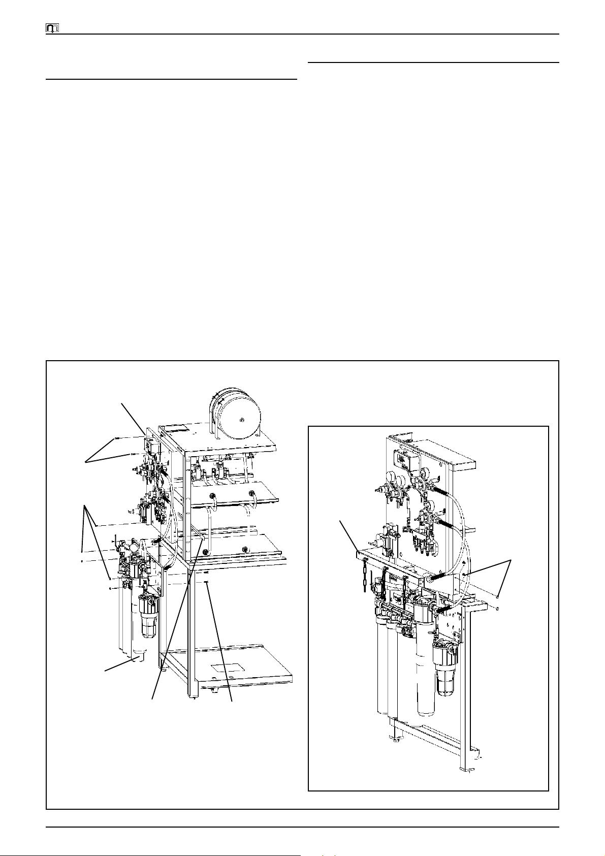
Unpacking the support stand and its components
1. Carefully remove the packaging material from the stand
Be careful not to discard any components when disposing of the carton.
2. Remove all of the components packed inside the stand
(Drip Pan, Accumulator Tank Kit, CO2 Control Panel,
Water Booster, and all of the installation hardware).
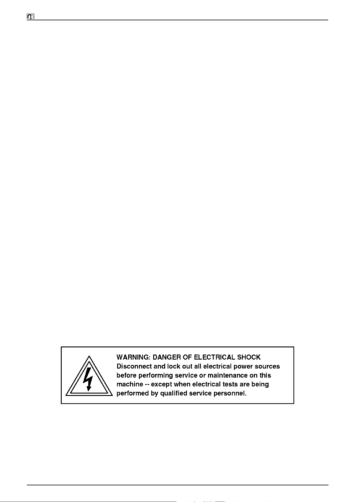
3. Remove the upper Bag-In-Box rack from the inside of
the lower stand (refer to figure 1). Remove the lower
shelf.
Un-packing the Support Stand
Lower Stand
Refrigeration Unit
Roll-out Tray
Support Stand Set-up
1
/4"-20 x 7/8"
HexHeadscrew
Note: Secure the top rack to the
lower stand with four (4) Hex
Head screws and Locking Nuts.
Lower Shelf
Upper Rack
Upper Rack for
Bag-In-Box Storage
Drip Pan
Setting-up the support stand
1. Place the upper rack on top of the lower stand. Align
the slots on both the Stand and Rack.
2. Locate the four (4) 1/4"-20 x 3/4" Hex Head screw and
Locking Nuts supplied in the bag of hardware. Bolt the
Upper Rack to the Lower Stand with the bolts and nuts.
Note: Do not tighten until the rack and stand are aligned.
3. Locate the upper rack with the back side of the rack
and stand flush. Tighten the bolts.
4. Position the Drip Pan in between the side channels of
the lower stand.
5. Roll the Roll-out Tray away from the support stand. To
do so, pull the rod on each side of the trays front until
a threaded hole is visible just behind the front legs on
each side (refer to figure 1).
6. Locate the two (2) 1/4"-20 x 1 1/2" Long Bolts, 1/4"-20
nuts, and split lock washers. Thread one (1) nut onto
each bolt, then insert a bolt each into the threaded holes.
The bolts should stop the trays forward motion (refer
to figure 1, Detail A).
7. Place the assembled stand into the desired location.
Level the stand by adjusting the feets level bolts located on all four (4) legs. Replace the lower shelf to its
original location.
1
/4"-20 StainlessSteel
Locking Nuts
Lower Stand
Refrigeration Unit
Roll-out Tray
Hex
Nut
1 1/2"
LongBolt
Lower Stand Leg
Lock
Washer
Roll-out Tray
Detail A: Tray Stop
Figure 1
8. The stand is now ready to install the Multiplex Refrigeration Unit and any standard accessories.
EI902005 Page 3 Issued (TFB/BT/BM/KAZ) 08/18/99
(English Section)
Page 8
Multiplex Company, Inc. Beverage Systems Operations Manual
Water Accumulator Tank Kit
Upper Rack
Top Plate
Thread fitting assembly onto the tank. Direct the
fittings towards the location of the Water Filter.
Figure 2
Mounting the Standard Accessories
Accumulator Tank Kit (refer to figure 2)
1. Locate the kit packaged with the stand. Remove all of
the components from the carton. Locate the fitting assembly and thread the fitting onto the tank.
Note: Use thread sealant to avoid leaks.
2. Identify the four (4) mounting holes located on the top
of the Upper Rack.
3. Mount the four (4) straps using the four (4) #10-32 screws
and nuts supplied in the kit.
4. Place the Accumulator Tank with the fittings facing the
rear of the stand and towards the side in which the
filter will be mounted to. Form the straps to match the
radius of the tank.
5. Bolt the two (2) strap sets together using the two (2)
1
/4"-20 screws and nuts (refer to figure 2).
CO2 Control Panel (refer to figure 3)
The CO2 Control Panel may be mounted on either side of
the stand or on the wall adjacent to the stand (not shown).
1. Locate the CO2 Control Panel also packed with the stand
and remove all components from the carton.
2. Determine on the stand the location of the Filter Package and the CO2 Control Panel.
3. Locate the two (2) mounting holes on the side of the
top of the Rack.
4. Mount the CO2 Control Panel using these two (2) holes
with the two (2) 1/4"-20 x 3/4" Long Screws and 1/4"-20
nuts provided with the stand installation kit.
5. Locate the lower hold-down Angle and two (2)
#10-32x1/2" Long Screws.
6. Attach the Angle to the backside of the Panel with
screws from the front side.
Tank Strap Hold Down
(forms to the tanks diameter)
#10-32 Mounting Screws and Nuts
(four [4] required)
Note: Rotate the gauges so they are visible from the front.
Turn gauges clockwise to tighten the threads to avoid any
leaks.
Water Filter Package (refer to figure 3)
1. Remove the Filter Package from the carton and locate
the mounting hardware.
Note: Mount the Filter Package on either the right or left
side of the stand. However, the left side is the recommended
side.
2. Locate the mounting slots on the lower stand legs. Insert the 1/4"-20 x 7/8" Long Screws from the inside of the
leg. Attach the 1/4"-20 Cap Nuts on the outside.
Note: Do not tighten these bolts completely (refer to figure3).
3. Position the Filter Panel on the bolts through the keyhole slots on the panel. Tighten the nuts completely.
CO2 Tank Bracket
1. Unpack the kit. Identify the Tank bracket and the mounting hardware supplied with the kit. (The optional mounting brackets supplied with the kit are not used for the
MV2000 Stand.)
2. Determine the side for the CO2 tanks. Identify the slots
on the upper rack for mounting.
Note: The tank bracket will clear the Filter Package so the
tank(s) may be on the same side as the Filter Package.
3. Attach the bracket to the legs of the stand with the
1
/2"-20x1/2" Hex Head Bolts and 1/4"-20 Cap Nuts.
Note: Insert Bolts from the inside of the leg and use the
Cap Nut on the outside of the leg. This must be done so the
removable shelf can be removed.
4. Tighten all nuts completely.
EI902005 Page 4 Issued (TFB/BT/BM/KAZ) 08/18/99
(English Section)
Page 9
Multiplex Company, Inc. Beverage Systems Operations Manual
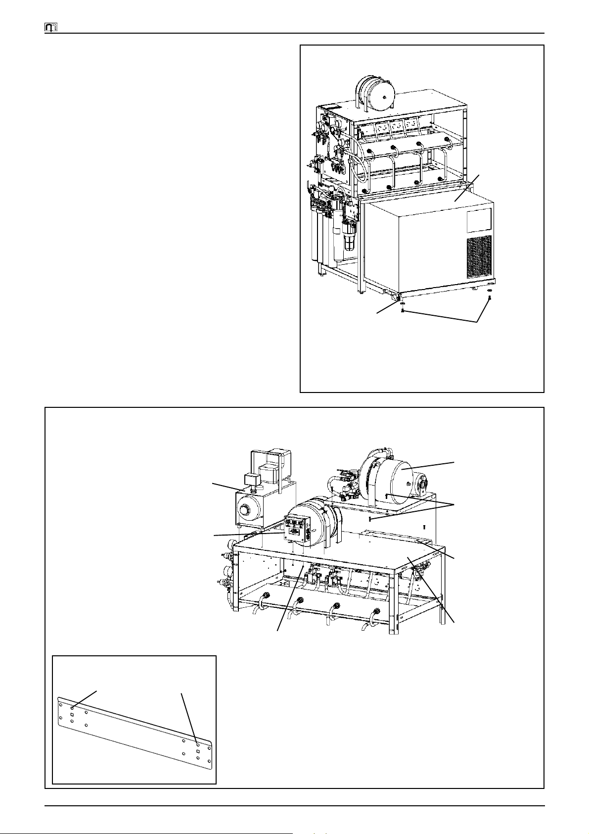
Procedure for mounting the refrigeration
unit to the support stand (refer to figure4)
1. Roll the Unit Tray out and block the front wheels while
placing the Refrigeration Unit onto the tray.
2. Place the unit on the tray towards the front and all the
way to the right (refer to figure 4).
3. From under the tray, align the two (2) holes up with the
bolt holes of the unit. Bolt the unit down using the bolt
supplied with the Refrigeration Unit installation kit.
4. Complete the remaining installation as stated in the
installation instructions provided with the unit.
Note: Additional instructions for routing the supply lines
are covered later in this publication. When connecting the
unit to the incoming power source, note that the unit will
need to be able to move forward approximately 30". When
the remote condenser unit is used, a minimum of two (2)
24" diameter coils must be used at the rear of the refrigeration unit to also allow it to be rolled out.
Mounting the optional accessories
Note: All accessories may not be required for all installations.
Water Booster Pump Assembly (refer to figure 5)
The Multiplex Model WBK10 Water Booster mounts on
the top right side of the upper rack.
1. Remove the Water Booster Pump from the carton.
2. Locate the mounting bracket supplied with the Booster
Assembly. Attach the bracket to the rear of the top with
raised lip towards the back of the stand. Fasten it with
two (2) 1/4"-20 x 3/4" Long Screws and 1/4"-20 nuts provided with the stand installation kit (refer to figure 5,
DetailA).
3. Place the Water Booster Pump Assembly on the top
over the bracket. Slide the assembly forward to allow
the rear of the panel to slip under the mounting bracket.
4. Attach the front of the panel to the top with two (2)
1
/4"-20 x 3/4" Long Screws and 1/4"-20 nuts provided with
the stand installation kit.
CO2 Control
Mounting Screws
and Nuts
(supplied with the
Support Stand)
CO2 Control Panel Mounting with Rack Style Water Filter Package
Panel
CO2 Tank Hold
Down Bracket
Mounting Screws
and Nuts
(supplied with the
Support Stand)
Water Filter
System
Angle
CO2 Control Panel
Mounting Bracket
Mounting Screws
and Nuts
(supplied with the
Support Stand)
Figure 3A
Figure 3
EI902005 Page 5 Issued (TFB/BT/BM/KAZ) 08/18/99
(English Section)
Page 10
Multiplex Company, Inc. Beverage Systems Operations Manual
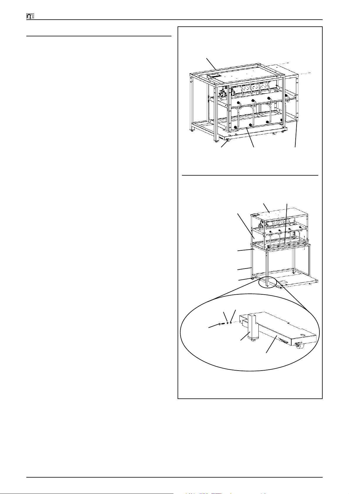
Air Compressor Assembly (refer to figure 5)
The Air Compressor mounts to the top of the upper rack on
the left side.
1. Remove the Air Compressor from the carton and remove the assembly from the shipping board.
2. Locate the four (4) mounting holes in the top and position the Air Compressor in place. Attach the Air Compressor using the hardware suppled with the Air Compressor.
3. Make the electrical connections to the compressor per
the instructions provided with the Air Compressor.
Accessories Switch Box (refer to figure 5)
1. Locate the Switch Control Box and the two (2) mounting screws.
2. Mount the Control Box with the switches facing toward
the front with the two (2) mounting screws from the
bottom side of the top.
3. Refer to figure 6 Accessory Switch Control Box Wir-
ing Diagram for component wiring connections.
Mounting the Refrigeration Unit to the Support Stand
Refrigeration Unit
Block Wheels
(prevents tray from rolling
while placing unit on tray)
Unit Mounting Bolts
(supplied with unit)
Detail A
Optional
AirCompressor
Accessories Switch
Control Box
Water Booster Pump Assembly
Switch Control Box
Mounting Screws
(supplied with Control Box)
Figure 4
Model WBK10
Water Booster System
Water Booster
Mounting Screws
and Nuts
(supplied with the
Water Booster)
Water Booster
Mounting Bracket
(supplied with the
Water Booster)
(refer to Detail A)
Top Plate of the Upper
Bag-In-Box Rack
Use these mounting holes
Figure 5
EI902005 Page 6 Issued (TFB/BT/BM/KAZ) 08/18/99
(English Section)
Page 11
Multiplex Company, Inc. Beverage Systems Operations Manual
Procedure for connecting the water
supply to the equipment package
(refer to the Water Circuit Diagram)
1. Identify the Main Water Supply. The supply should comply with all local plumbing codes and be equipped with
a Manual Shut-off Valve.
2. Locate the 1/2" ID blue poly tubing supplied with the
Filter Package.
3. Connect one (1) end of the tube to the Water Supply
and the other end to the Filter Package Inlet per the
filter installation instructions.
3. Route another piece of tubing out of the Filter Package
Outlet to the Accumulator Tank up the side of the stand
and over the top to the tank.
Note: If the optional Booster Pump is required, connect it
between the Course Filter and the Fine Filter. Refer to the
Booster Pump installation instructions for the correct connection method.
4. Route all tubing up the side of the stand and over the
top to the Booster Pump.
5. Connect the tube per the installation instructions provided with the Filter Package. Route another piece of
tubing from the Accumulator tank to the Water Regulator located on the CO2 Control Panel.
6. Connect the tube per the installation instructions supplied with the CO2 Control Panel.
7. Locate the Inlet water line supplied on the Refrigeration Unit. Route the line out the conduit opening and
up to the CO2 Control Panel Water supply to the Refrigeration unit.
Note: Loop the line towards the unit tray to allow the unit
to moved in and out for service.
8. Connect the line per the installation instructions provided with the Refrigeration Unit.
How to connect the CO2 (Air) supply to the equipment package
1. Identify the CO2 Supply source. Route a line to the CO2
Control Panel and connect it to the manifold on the
CO2 Control Panel per the installation instructions.
Note: If CO2 Tank Kit is required, attach the Regulator
Manifold Assembly to the tank(s). Route the line to the CO2
Control Panel per the installation instructions.
2. If the Optional Air Compressor Kit is required, route
the outlet line from the Air Compressor through the
CO2 Control Panel and connect per the Installation instructions.
3. Uncoil the line located on the last pump on the Bag-InBox Pump Panel.
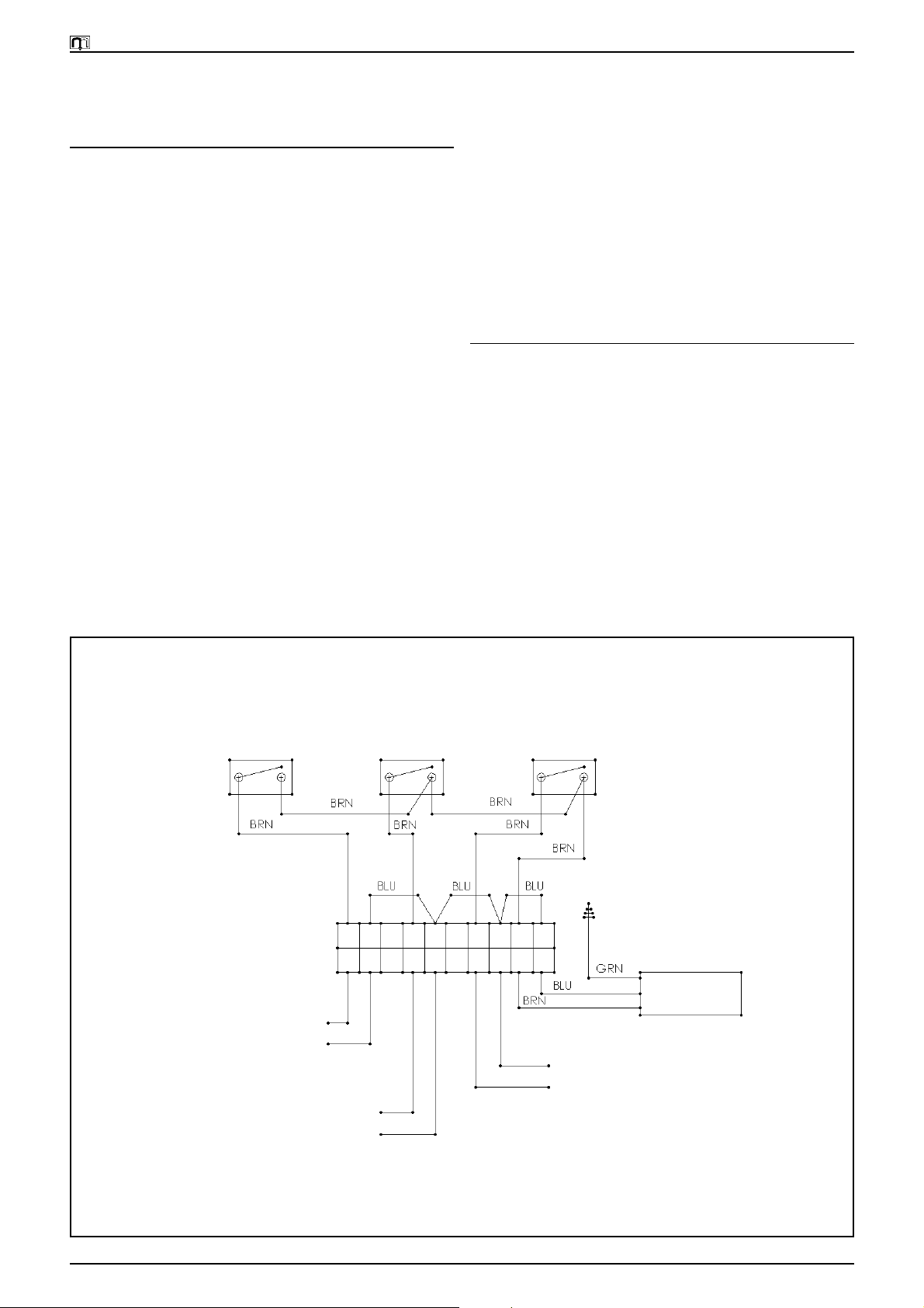
Accessory Switch Control Box Wiring Diagram
Air Compressor CO2 Alarm Water Booster
Connect the
AirCompressor here
220 VAC, 50Hz
Connect the
CO2Alarm here
Figure 6
EI902005 Page 7 Issued (TFB/BT/BM/KAZ) 08/18/99
(English Section)
Page 12
Multiplex Company, Inc. Beverage Systems Operations Manual
4. Route the line out the side and to the CO2 Regulator on
the CO2 Control Panel.
5. Connect the line to the CO2 Control Panel Regulator
per the installation instructions provided with the CO2
Control Panel.
6. Locate the CO2 Supply Line inside the Refrigeration
Unit.
7. Route the line out the conduit opening and to the CO2
Control Panel (refer to figure 6). Be sure to loop the
line down towards the unit tray to allow the unit to roll
in and out for service.
8. Connect the line to the CO2 Control Panel per the installation instructions of the CO2 Control Panel.
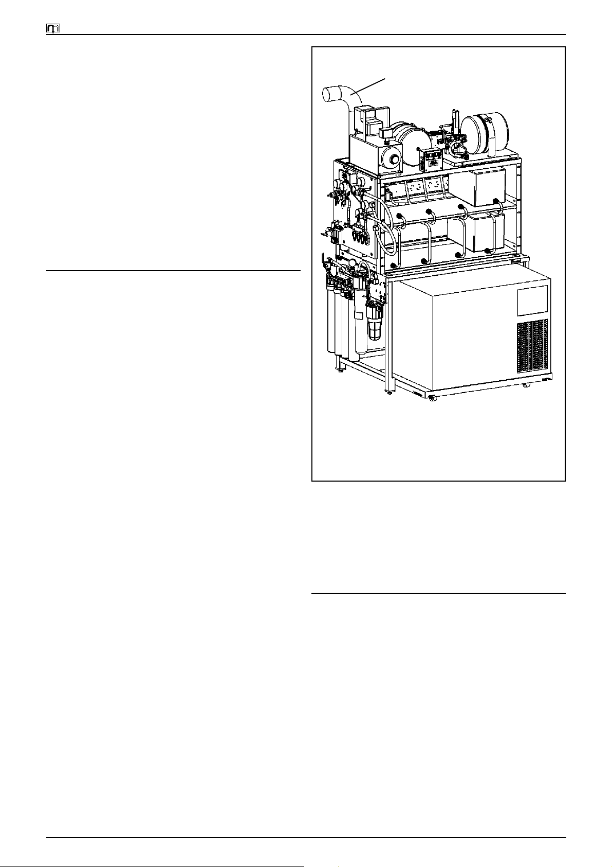
Connecting the refrigeration units
supply conduits (refer to figure 7)
Routing the syrup supply conduit and connecting it to the pumps
1. With the Roll-out tray pulled out, remove the top cover
and locate the Syrup Supply Lines.
2. Route the tubes out of the side conduit opening and
bundle these lines together.
Connecting the Refrigeration Units Supply Conduits
Recirculating Conduit
3. Loop the bundle towards the tray and then back to the
pump panel. This ensures there is enough length to
allow the tray to roll in and out.
4. Connect the product supply lines to the pump. Be sure
the match the numbers on the lines to the numbers on
the pump.
5. Clamp the lines in place using the clamps provided
with the Refrigeration installation kit.
Connecting the Recirculating Conduit
1. Locate the Recirculating Conduit at the conduit chase.
For overhead conduit, route the conduit through the
square hole in the top of the upper rack and down the
back side of the stand.
2. Loop the conduit towards the tray and back up through
the side conduit opening to guarantee there is enough
length to allow the tray to roll in and out.
3. Connect the conduit to the cooling coils per the installation instructions provided with the Refrigeration Unit.
Loop Recirculating Conduit and Syrup Lines
(towards the bottom of the tray as shown to
allow the tray to be rolled in and out)
Figure 7
Loading the Bag-In-Box Syrup Supply
The numbering configuration for the Bag-In-Box is the odd
numbers go on the top shelf and the even numbers are on
the bottom. Each syrup flavor will require two (2) Bag-InBox on the shelf, side by side. Load the shelves with the
required products and install the connectors to the Bag-InBox.
Starting the system up
The system should now be ready for start-up. The Refrigeration Unit installation instructions will provide the steps
required to start the System. After completing those instructions, the Multiplex MV2000 Beverage System installation
is complete.
EI902005 Page 8 Issued (TFB/BT/BM/KAZ) 08/18/99
(English Section)
Page 13
Multiplex Company, Inc. Beverage Systems Operations Manual
Model MV2000 Water Circuit Diagram
EI902005 Page 9 Issued (TFB/BT/BM/KAZ) 08/18/99
(English Section)
Page 14

Page 15

Instructions de Montage pour Appareil de
Boissons Multiplex pour le
Distributeur de Boissons
Modèle MV2000
French Section
Page 16

Multiplex Company, Inc. Beverage Systems Operations Manual
Avertissement: Pour éviter de graves accidents
Important: Lisez les avertissements suivants avant de débuter linstallation afin
déviter tout risque daccident grave ou de danger de mort.
RESPECTEZ tous les Codes de Sécurité de Plomberie et Electriques,
Nationaux et Locaux.
PLACEZ tous les interrupteurs électriques sur la position «arrêt» pendant
lentretien, linstallation et la réparation de lappareil.
VERIFIEZ que tous les raccords coniques sur le (les) réservoir (s) de
carbonatation sont bien étanches. Utilisez une clé lors du
contrôle pour obtenir des joints de bonne qualité.
CONTROLEZ la pression des Régulateurs avant la mise en route de lappareil.
PROTEGEZ-VOUS les yeux lorsque vous travaillez à proximité des réfrigérants.
SOYEZ TOUJOURS PRUDENT lorsque vous manipulez les bords des surfaces métalliques de
lappareil.
MANIPULEZ les bouteilles de CO2 et les indicateurs avec soin. Protégez les
bouteilles contre labrasion.
STOCKEZ la (les) bouteille (s) de CO2 dans des endroits bien ventilés.
NE JETEZ PAS et ne pas laissez tomber une bouteille de CO2. Maintenez la (les)
bouteille (s) en position debout à laide dune chaîne.
NE RACCORDEZ PAS la (les) bouteille (s) de CO2 directement au récipient de produit.
Cela peut provoquer une explosion et tuer ou blesser quelquun.
La (les) bouteille (s) doivent dabord être raccordées à un (des)
régulateur (s).
NE STOCKEZ PAS les bouteilles de CO2 près de fourneaux, de radiateurs ou de
sources de chaleur où la température est supérieure à 125°F
(51,7° C).
NE TENTEZ PAS DE VIDER le gaz CO2 dune bouteille usagée.
NE TOUCHEZ PAS les Conduites de Réfrigération situées à lintérieur des unités.
Leur température peut parfois dépasser 200°F (93,3°C).
EI902005 Page 12 Issued (TFB/BT/BM/KAZ) 08/18/99
(French Section)
Page 17

Multiplex Company, Inc. Beverage Systems Operations Manual
Introduction
Le Distributeur de Boissons Multiplex MV2000 est un
système de stockage compact en rack. Ce système en rack
permet de stocker huit (8) cubitainers avec les Pompes à
Boissons et les Vannes dInversion. Les autres composants
standard fournis avec ce Comptoir sont notamment un
Réservoir dEmmagasinage dEau et un Panneau de
Commande dAlimentation en CO2. Le Réservoir
dEmmagasinage dEau maintient une pression deau
constante dans le système. Le Panneau de Commande
dAlimentation en CO2 régule lalimentation en CO2 des
Pompes à Boissons et de la Fabrique de Soude.
Le Distributeur de Boissons MV2000 est fourni avec un
Compresseur dAir, une Pompe de Surpresseur dEau, un
Dispositif de Filtration dEau et un Support de Réservoir de
CO2. La plupart des composants peuvent être montés
directement sur le Comptoir. Les accessoires peuvent être
installés sur un mur si la disposition du magasin lexige.
Déballage du Comptoir et de ses composants
1. Retirez soigneusement les matériaux demballage du
Comptoir. Vérifiez quaucun composant na été oublié
dans le carton avant de le jeter.
2. Retirez tous les composants emballés à lintérieur du
Comptoir (Collecteur de Condensat, Kit du Réservoir
dEmmagasinage, Panneau de Commande de CO2,
Surpresseur dEau et tous les éléments de montage).
3. Retirez le rack supérieur de Cubitainers de lintérieur
du Comptoir inférieur (voir figure 1). Retirez létagère
inférieure.
Installation du Comptoir
1. Placez le rack supérieur sur le Comptoir inférieur.
Utilisez les fentes pour les aligner.
2. Repérez les quatre (4) Vis à Tête Hexagonale et Ecrous
de Blocage 1/4"-20 x 3/4" fournis dans le sac de visserie.
Fixez le Rack Supérieur sur le Comptoir Inférieur à laide
des boulons et des écrous.
Remarque: Ne serrez pas avant davoir aligné le Rack et le
Comptoir.
Déballage du Comptoir
Comptoir Inférieur
Plateau Roulant du
Dispositif de
Réfrigération
Montage Du Comptoir
Vis à tête hexagonale
1
/4"-20 x 7/8"
Remarque: Fixez le rack
supérieur sur le Comptoir
inférieur à laide des quatre
(4) Vis à tête hexagonale et
Ecrous de blocage.
Ecrous de blocage 1/4"-20
en Acier Inoxydable
Comptoir Inférieur
Plateau Roulant du
Dispositif de Réfrigération
Rondelle
Ecrou
hexagonal
Etagère
Inférieure
Rack Supérieur
Frein
Rack Supérieur
pour Stockage des
Cubitainers
Collecteur de
Condensat
3. Repérez lendroit où larrière du Rack supérieur et le
Comptoir se touchent. Serrez les boulons.
4. Installez le Collecteur de Condensat entre les profilés
Grand
Boulon 11/2"
Pied du Comptoir Inférieur
latéraux du Comptoir inférieur.
5. Sortez le Plateau Roulant du Comptoir. Pour cela, tirez
sur la tige située de chaque côté de lavant du plateau
Plateau Roulant
Détail A: Arrêt du Plateau
jusquà ce quun trou taraudé apparaisse juste derrière
les pieds avant de chaque côté (voir figure 1).
6. Repérez les deux (2) Grands Boulons 1/4"-20 x 1 1/2",
les écrous 1/4"-20 et les rondelles de blocage fendues.
Installez un (1) écrou sur chaque boulon, puis
introduisez les boulons dans les trous taraudés. Les
boulons doivent stopper le mouvement en avant du
plateau (voir figure 1, Détail A).
7. Installez le Comptoir assemblé à lendroit souhaité.
Réglez la hauteur du Comptoir à laide des boulons de
réglage situés sur les quatre (4) pieds. Réinstallez
létagère inférieure dans sa position dorigine.
Figure 1
8. Le Dispositif de Réfrigération Multiplex et les
accessoires standard peuvent à présent être installés sur
le Comptoir.
EI902005 Page 13 Issued (TFB/BT/BM/KAZ) 08/18/99
(French Section)
Page 18

Multiplex Company, Inc. Beverage Systems Operations Manual
kit du Réservoir dEmmagasinage dEau
Plaque Supérieure du
Rack Supérieur
Installez les éléments de montage sur le réservoir.
Orientez les fixationsvers lemplacement du Filtre dEau.
Butée dancrage de Sangle du réservoir
Figure 2
Montage des Accessoires Standard
Kit du Réservoir dEmmagasinage (voir figure 2)
1. Repérez le kit emballé avec le Comptoir. Retirez tous
les composants du carton. Repérez les éléments de
montage et installez-les sur le réservoir.
Remarque: Utilisez du mastic détanchéité pour éviter les
fuites.
2. Repérez les quatre (4) trous de montage sur le dessus
du Rack Supérieur.
3. Installez les quatre (4) sangles à laide des quatre (4) vis
et écrous #10-32 fournis avec le kit.
4. Installez le Réservoir dEmmagasinage avec les fixations
face à larrière du Comptoir et du côté où le filtre sera
installé. Réglez les sangles en fonction de la position
du réservoir.
5. Vissez les deux (2) jeux de sangles ensemble à laide
des deux (2) vis et écrous 1/4"-20 (voir figure 2).
Panneau de Commande de CO2 (voir figure 3)
Le Panneau de Commande de CO2 peut être monté dun
côté ou de lautre du Comptoir ou sur le mur adjacent au
Comptoir (non représenté).
1. Repérez le Panneau de Commande de CO2 également
emballé avec le Comptoir et retirez tous les composants
du carton.
2. Déterminez sur le Comptoir lemplacement du
Dispositif de Filtration et du Panneau de Commande
de CO2.
3. Repérez les deux (2) trous de montage en haut du Rack,
sur le côté.
4. Installez le Panneau de Commande de CO2 en utilisant
ces deux (2) trous et à laide des deux (2) Grandes Vis
1
/4"-20 x 3/4" et des écrous 1/4"-20 fournis dans le kit de
montage du Comptoir.
(forme le diamètre du réservoir)
Vis et Ecrous de Montage #10-32
(quatre [4])
5. Repérez lAngle de retenue inférieur et deux (2) Grandes
Vis #10-32 x 1/2".
6. Fixez lAngle à larrière du Panneau à laide des vis de
la face avant.
Remarque: Tournez les indicateurs de façon à ce quils
soient visibles de lavant. Tournez-les dans le sens horaire
pour serrer les filetages et empêcher les fuites.
Dispositif de Filtration dEau (voir figure 3)
1. Retirez le Dispositif de Filtration du carton et repérez
les éléments de montage.
Remarque : Vous pouvez installer le Dispositif de Filtration sur le côté droit ou gauche du Comptoir. Il est toutefois
conseillé de choisir le côté gauche.
2. Repérez les fentes de montage sur les pieds du Comptoir
inférieur. Introduisez les Grandes Vis 1/4"-20 x 7/8" à
lintérieur du pied. Fixez les Ecrous Borgnes 1/4"-20 à
lextérieur.
Remarque: Ne serrez pas complètement ces boulons (voir
figure 3).
3. Positionnez le Panneau Filtrant sur les boulons à laide
des fentes en trou de serrure du panneau. Serrez les
écrous complètement.
Support de Réservoir de CO2
1. Déballez le kit. Repérez le Support de Réservoir et les
éléments de montage livrés avec le kit. (Les supports
de montage optionnels fournis avec le kit ne sont pas
utilisés avec le Comptoir MV2000.)
2. Déterminez de quel côté seront placés les Réservoirs
de CO2. Repérez les fentes de montage sur le Rack
supérieur.
Remarque: Le support du réservoir cachera le Dispositif de
Filtration; le (les) réservoir(s) peut (peuvent) donc être du
même côté que le Dispositif de Filtration.
EI902005 Page 14 Issued (TFB/BT/BM/KAZ) 08/18/99
(French Section)
Page 19

Multiplex Company, Inc. Beverage Systems Operations Manual
3. Fixez le support sur les pieds du Comptoir à laide des
Boulons à Tête Hexagonale 1/2"-20 x 1/2" et des Ecrous
Borgnes 1/4"-20.
Remarque: Introduisez les Boulons à lintérieur du pied et
utilisez un Ecrou Borgne à lextérieur du pied. Cela permet
de retirer létagère amovible.
4. Serrez complètement tous les écrous.
Procédure de montage du dispositif de
réfrigération sur le Comptoir
(voirfigure4)
1. Sortez le Bloc Plateau et bloquez les roues avant pendant que vous installez le Dispositif de Réfrigération
sur le plateau.
2. Placez le dispositif sur le plateau, vers lavant et à droite
(voir figure 4).
3. Alignez les deux (2) trous sous le plateau avec les trous
de boulon du dispositif. Fixez le dispositif à laide des
boulons fournis dans le kit de montage du Dispositif de
réfrigération.
4. Terminez linstallation conformément aux instructions
de montage fournies avec le dispositif.
Remarque : Des instructions supplémentaires concernant
linstallation des conduites dalimentation sont fournies plus
loin. Pour pouvoir être raccordé à une source dalimentation
électrique, le dispositif devra pouvoir savancer denviron
30". Si le groupe compresseur-condensateur séparé est
utilisé, au moins deux (2) bobines de diamètre 24" seront
également nécessaires à larrière du dispositif de
réfrigération pour pouvoir lavancer.
Montage des accessoires optionnels
Remarque: Tous les accessoires ne seront peut-être pas nécessaires pour linstallation.
Groupe Pompe de Surpresseur dEau (voir figure 5)
Le Surpresseur dEau Multiplex Modèle WBK10 sinstalle
sur le côté supérieur droit du Rack supérieur.
1. Retirez la Pompe de Surpresseur dEau du carton.
2. Repérez le support de montage fourni avec le Groupe
de Surpression. Fixez le support en haut à larrière, avec
la lèvre remontée tournée vers larrière du Comptoir.
Fixez-le à laide de deux (2) Grandes Vis 1/4"-20 x 3/4"
et des écrous 1/4"-20 fournis avec le kit de montage du
Comptoir (voir figure 5, Détail A).
Montage du Panneau de Commande de CO2 avec Dispositif de Filtration dEau en Rack
Panneau de
Commande de CO2
Vis et Ecrous de
Montage
(fournis avec le
Comptoir)
CO2 Tank Hold
Down Bracket
Vis et Ecrous de
Montage
(fournis avec le
Comptoir)
Système de
Filtration dEau
Angle
CO2 Control Panel
Mounting Bracket
Vis et Ecrous de
Montage
(fournis avec le
Comptoir)
Figure 3A
Figure 3
EI902005 Page 15 Issued (TFB/BT/BM/KAZ) 08/18/99
(French Section)
Page 20

Multiplex Company, Inc. Beverage Systems Operations Manual
3. Placez le Groupe Pompe de Surpresseur dEau sur le
dessus du support. Faites coulisser le groupe en avant
pour que larrière du panneau puisse glisser sous le
support de montage.
4. Fixez lavant du panneau sur la partie supérieure à laide
de deux (2) Grandes Vis 1/4"-20 x 3/4" et des écrous 1/4"20 fournis avec le kit de montage du Comptoir.
Groupe Compresseur dAir (voir figure 5)
Le Compresseur dAir sinstalle sur le haut du Rack
supérieur, du côté gauche.
1. Retirez le Compresseur dAir du carton et Retirez les
fixations de leur carton demballage.
2. Repérez les quatre (4) trous de montage en haut et
positionnez le Compresseur dair. Fixez-le à laide des
éléments de montage fournis.
3. Effectuez les branchements électriques conformément
aux instructions fournies avec le Compresseur dAir.
Boîtier de Commande des Accessoires (voir figure 5)
1. Repérez le Boîtier de Commande ainsi que les deux
(2) vis de montage.
2. Installez le Boîtier de Commande, les commutateurs
face à lavant, sur le côté inférieur du haut. Utilisez
pour cela les deux (2) vis de montage.
3. Voir figure 6 «Schéma de Câblage du Boîtier de
Commande des Accessoires» pour le branchement des
composants.
Montage du Dispositif de Réfrigération sur le Comptoir
Dispositif de
Réfrigération
Roues de Blocage
(empêchent le plateau
davancer pendant le
positionnement du
dispositif sur le plateau)
Boulons de Montage du
Dispositif (fournis avec
le dispositif)
Figure 4
Compresseur
dAir Optionnel
Boîtier de Commande
des Accessoires
Détail A
Utilisez ces trous de
montage
Groupe Pompe de Surpresseur dEau
Vis de Montage du Boîtier de
Commande (fournies avec le
Boîtier de commande)
Surpresseur dEau
Modèle WBK10
Vis et Ecrous de
Montage du
Surpresseur dEau
(fournis avec le
Surpresseur dEau)
Support de
Montage du
Surpresseur dEau
(fourni avec le
Surpresseur dEau)
(voir détail A)
Plaque Supérieure du
Rack Supérieur de
Cubitainers
Figure 5
EI902005 Page 16 Issued (TFB/BT/BM/KAZ) 08/18/99
(French Section)
Page 21

Multiplex Company, Inc. Beverage Systems Operations Manual
Procédure de raccordement de
lalimentation deau à léquipement
(voir Schéma de Circuit de lEau)
1. Repérez lAlimentation dEau Principale. Lalimentation
doit être conforme à tous les codes de plomberie locaux
et comprendre une Vanne de Coupure Manuelle.
2. Repérez le tubage en plastique bleu 1/2" fourni avec le
Dispositif de Filtration.
3. Connectez (1) un bout du tube à lAlimentation dEau
et lautre extrémité à lEntrée du Dispositif de Filtration, conformément aux instructions de montage du
filtre.
4. Connectez un autre morceau de tube entre la Sortie du
Dispositif de Filtration et le Réservoir dEmmagasinage
en le faisant passer sur le côté du Comptoir et par le
haut.
Remarque: Si la Pompe de Surpresseur optionnelle est
utilisée, branchez-la entre le Filtre Dégrossisseur et le Filtre
Fin. Consultez les instructions de montage de la Pompe de
Surpresseur pour connaître la méthode correcte de
connexion.
5. Connectez tous les tubes à la Pompe de Surpresseur en
les faisant passer sur le côté du Comptoir et par le haut.
6. Connectez le tube conformément aux instructions de
montage fournies avec le Dispositif de Filtration.
Connectez un autre morceau de tube entre le Réservoir
Schéma de Câblage du Boîtier de Commande des Accessoires
dEmmagasinage et le Régulateur dEau situé sur le
Panneau de commande de CO2.
7. Connectez le tube conformément aux instructions de
montage fournies avec le Panneau de commande de
CO2.
8. Repérez la conduite dentrée deau sur le Dispositif de
Réfrigération. Connectez la conduite à louverture de
conduite et à lAlimentation dEau du Dispositif de
Réfrigération sur le Panneau de commande de CO2.
Remarque: Enroulez la conduite à côté du Bloc Plateau de
façon à pouvoir ouvrir et fermer le bloc pour lentretien.
9. Branchez la conduite conformément aux instructions
de montage fournies avec le Dispositif de Réfrigération.
Comment brancher lalimentation (dair)
de CO2 à léquipement
1. Repérez la Source dalimentation de CO2 et raccordez
une conduite au collecteur du Panneau de Commande
de CO2, conformément aux instructions de montage.
Remarque : Si le Kit Réservoir de CO2 est utilisé, fixez le
Groupe Collecteur Régulateur au(x) réservoir (s). Connectez
la conduite au Panneau de Commande de CO2
conformément aux instructions de montage.
2. Si le kit Compresseur dAir Optionnel est utilisé,
connectez la conduite de sortie du Compresseur dAir
Compresseur dAir Alarme CO2 Surpresseur dEau
Branchez le Compresseur
dAir ici
Branchez lAlarme
CO2 ici
220 V c.a., 50 Hz
Figure 6
EI902005 Page 17 Issued (TFB/BT/BM/KAZ) 08/18/99
(French Section)
Page 22

Multiplex Company, Inc. Beverage Systems Operations Manual
dans le Panneau de Commande de CO2 conformément
aux instructions de montage.
3. Déroulez la conduite située sur la dernière pompe du
Panneau de Pompes de Cubitainers.
4. Branchez la conduite sur le Régulateur de CO2 du
Panneau de commande de CO2, en passant sur le côté.
5. Effectuez le branchement de la conduite sur le
Régulateur du Panneau de commande de CO2
conformément aux instructions de montage fournies
avec le Panneau de commande de CO2.
6. Repérez la Conduite dAlimentation de CO2 à lintérieur
du Dispositif de Réfrigération.
7. Connectez la conduite à louverture de conduite et au
Panneau de Commande de CO2 (voir figure 6). Veillez
à bien enrouler la conduite à côté du bloc plateau pour
que ce dernier puisse être ouvert et refermé pour
lentretien.
8. Effectuez le raccordement de la conduite sur le Panneau
de Commande de CO2 conformément aux instructions
de montage du Panneau de Commande de CO2.
Branchement des conduites
dalimentation du dispositif de
réfrigération (voir figure 7)
Branchement des Conduites dAlimentation du
Dispositif de Réfrigération
Conduite de Recirculation
Installation et raccordement aux pompes de la conduite
dalimentation de sirop
1. Ouvrez le plateau roulant puis retirez le couvercle
supérieur et repérez les Conduites dAlimentation de
Sirop.
2. Connectez les tubes à louverture de conduite latérale
puis attachez-les ensemble.
3. Enroulez-les à côté du plateau et du panneau des
pompes pour que la longueur soit suffisante pour ouvrir
et refermer le plateau.
4. Connectez les conduites dalimentation de produit à la
pompe. Veillez à bien respecter les numéros indiqués
sur les conduites et sur la pompe.
5. Fixez les conduites à laide des fixations fournies dans
le kit de montage de Réfrigération.
Branchement de la Conduite de Recirculation
1. Repérez la Conduite de Recirculation sur le châssis de
conduite. Les conduites en hauteur doivent passer dans
le trou carré en haut du Rack supérieur et descendre
au dos du Comptoir.
2. Enroulez la conduite à côté du plateau et de louverture
de conduite latérale de façon à disposer dune longueur
suffisante pour ouvrir et fermer le plateau.
Enroulez la Conduite de Recirculation et les
Conduites de Sirop (à côté du plateau,
comme indiqué, pour permettre louverture
et la fermeture du plateau)
Figure 7
3. Connectez la conduite aux serpentins de
refroidissement, conformément aux instructions de
montage fournies avec le Dispositif de Réfrigération.
Chargement de lalimentation en Sirop des cubitainers
Le système de numérotation des cubitainers est le suivant:
les numéros impairs vont sur létagère supérieure, les
numéros pairs vont en bas. Il devra y avoir deux (2)
Cubitainers côte à côte sur létagère pour chaque arôme de
sirop. Remplissez les étagères avec les produits souhaités
et installez les connecteurs des Cubitainers.
Mise en route du système
Le système est maintenant prêt à lemploi. Les instructions
de montage du Dispositif de Réfrigération décrivent les
étapes à suivre pour la mise en route du Système. Une fois
ces instructions mises en pratique, linstallation du
Distributeur de Boissons MV2000 Multiplex est terminée.
EI902005 Page 18 Issued (TFB/BT/BM/KAZ) 08/18/99
(French Section)
Page 23

Multiplex Company, Inc. Beverage Systems Operations Manual
Schéma de Circuit de lEau du Modèle MV2000
EI902005 Page 19 Issued (TFB/BT/BM/KAZ) 08/18/99
(French Section)
Page 24

Page 25

Istruzioni per linstallazione di un distributore
di bevande Multiplex
Sistema di distribuzione
bevande Modello MV2000
Italian Section
Page 26

Multiplex Company, Inc. Beverage Systems Operations Manual
Attenzione: per evitare lesioni gravi
Importante: Leggere le seguenti avvertenze prima di procedere con linstallazione.
La mancata osservanza potrebbe portare a rischio di morte o di gravi lesioni.
DA FARE Rispettare tutte le normative nazionali e locali riguardo la sicurezza idraulica ed
elettrica.
DA FARE Mettere in posizione off (spento) tutti gli interruttori di servizio elettrici in entrata
mentre si eseguono lavori si assistenza, installazione o riparazione sullapparecchio.
DA FARE Controllare che tutti gli innesti sul /sui serbatoio/i di carbonatazione siano a tenuta.
Questo controllo va eseguito con laiuto di una chiave inglese, per garantire una
valida sigillatura.
DA FARE Verificare la pressione sui Regolatori prima di avviare lapparecchio .
DA FARE Proteggere gli occhi mentre si eseguono lavori in prossimità di refrigeranti.
DA FARE Usare cautela quando si maneggiano i bordi delle superfici di metallo
dellapparecchio.
DA FARE Maneggiare con cura le bombole e gli indicatori di livello di CO2. Assicurare
adeguatamente le bombole contro le abrasioni.
DA FARE Riporre le bombole di CO2 in zone ben ventilate.
NON Rovesciare o far cadere una bombola di CO2. Bloccare la bombola (bombole) in
posizione verticale per mezzo di una catena.
NON Collegare direttamente la/le bombola/e di CO2 al contenitore del prodotto. Tale
operazione porterebbe ad unesplosione che potrebbe causare morti o feriti. E più
opportuno collegare la/le bombola/e di CO2 ad un regolatore (regolatori).
NON Riporre le bombole di CO2 in presenza di temperature superiori ai 125°F (51.7°C),
vicino a caldaie, caloriferi o fonti di calore.
NON Far fuoriuscire lanidride carbonica da vecchie bombole.
NON Toccare le linee di refrigerazione allinterno degli apparecchi, alcune potrebbero
avere temperature superiori ai 200°F (93.3°C).
EI902005 Page 22 Issued (TFB/BT/BM/KAZ) 08/18/99
(Italian Section)
Page 27

Multiplex Company, Inc. Beverage Systems Operations Manual
Introduzione
Il Sistema di distribuzione bevande Multiplex MV2000 è
un sistema compatto di distribuzione da banco. Il sistema è
in grado di contenere fino a otto (8) Bag-in-Box complete di
pompe di distribuzione bevande e valvole di conversione.
Gli altri componenti standard forniti con il banco
comprendono un serbatoio di accumulo per lacqua ed un
pannello di controllo alimentazione CO2. Il serbatoio di
accumulo dellacqua mantiene costante la pressione
dellacqua nel sistema. Il pannello di controllo
alimentazione CO2.alimenta sia le pompe di distribuzione
bevande sia lunità di produzione della soda.
Gli accessori per il Sistema di distribuzione bevande
MV2000 comprendono un compressore daria, una pompa
di sovralimentazione acqua, ununità filtrante per lacqua
ed un supporto per il serbatoio di CO2. Il banco è progettato
in modo da poter montare la maggior parte dei componenti
direttamente sul banco stesso. Gli accessori possono essere
montati su di una parete se la configurazione lo richiede.
Disimballaggio del banco di supporto e dei suoi componenti
1. Rimuovere attentamente il materiale di imballaggio dal
banco. Prestare attenzione a non eliminare nessuno dei
componenti nel gettare via il cartone.
2. Togliere tutti i componenti imballati allinterno del
banco (cassetto raccoglicocce, kit di montaggio
serbatoio di accumulo, pannello di controllo CO2,
sovralimentatore dellacqua, e tutti gli attrezzi per
linstallazione).
3. Estrarre il supporto superiore con le Bag-in-Box
dallinterno del banco inferiore (vedi figura 1). Togliere
il ripiano inferiore.
Disimballaggio del banco di supporto
Banco inferiore
Carrello estraibile per unità
di refrigerazione
Allestimento banco di supporto
Viti esagonali
1
/4"-20 x 7/8"
Attenzione: fissare il supporto
superiore al banco inferiore
con quattro (4) viti esagonali e
dadi di bloccaggio.
Dadi di bloccaggio in
acciaio inossidabile 1/4"20
Ripiano
inferiore
Supporto
superiore
Supporto superiore
per lallineamento
di Bag-in-Box
Cassetto
raccogli gocce
Allestimento del banco di supporto
1. Posizionare il supporto superiore sopra il banco
inferiore. Allineare i fori del banco e del supporto.
2. Posizionare le quattro(4) viti esagonali 1/4"-20 x 3/4" e i
dadi di fissaggio forniti nella borsa degli attrezzi.
Avvitare il supporto superiore al banco inferiore con
bulloni e dadi.
Attenzione: Non chiudere completamente finché supporto
e banco non sono allineati.
3. Mettere in posizione il supporto superiore con il lato
posteriore e lo scarico del banco. Fissare i bulloni.
4. Collocare il cassetto raccogligocce tra i canali laterali
del supporto inferiore.
5. Estrarre il carrello estraibile dal banco di supporto. Per
fare questo, tirare le aste su entrambi i lati della parte
anteriore del carrello, fino a quando non è visibile un
foro filettato appena dietro le gambe anteriori, su
entrambi i lati (vedi figura 1).
6. Posizionare i due (2) bulloni lunghi 1/4"-20 x 1 1/2", i
dadi 1/4"-20, e le rondelle di fissaggio aperte. Avvitare
un (1) dado su ogni bullone, quindi inserire un bullone
in ogni foro filettato. I bulloni dovrebbero servire ad
arrestare il movimento in avanti del carrello (vedi figura
1, particolare A).
Banco inferiore
Carrello estraibile per
unità di refrigerazione
Dado
esagonale
Bullone
lungo 11/2"
Gamba banco
Rondelle di
fissaggio
inferiore
Carrello estraibile
Particolare A: arresto carrello
Figura 1
7. Mettere il banco così montato nella posizione
desiderata. Mettere a livello il banco regolando i bulloni
posti su tutte e quattro (4) le gambe. Riporre il ripiano
inferiore nella sua posizione iniziale.
8. Il banco è ora pronto per linstallazione dellunità di
refrigerazione Multiplex e di tutti gli accessori standard.
EI902005 Page 23 Issued (TFB/BT/BM/KAZ) 08/18/99
(Italian Section)
Page 28

Multiplex Company, Inc. Beverage Systems Operations Manual
Kit serbatoio di accumulo acqua
Piano superiore
supporto superiore
Gruppo innesti filettati per il serbatoio. Direzionare gli
innesti verso la postazione del filtro per lacqua.
Figura 2
Montaggio degli accessori standard
Kit di montaggio serbatoio di accumulo (vedi figura 2)
1. Individuare il kit di montaggio imballato insieme al
banco. Togliere tutti i componenti dal cartone. Individuare il gruppo di innesti ed avvitarli sul serbatoio.
Attenzione: Utilizzare del sigillante per filetti per evitare
perdite.
2. Identificare i quattro (4) fori di montaggio posti sopra il
supporto superiore.
3. Montare le quattro (4) staffe usando le quattro (4) viti
#10-32 e i bulloni forniti con il kit.
4. Posizionare il serbatoio di accumulo con gli innesti
rivolti verso il retro del banco e verso il lato su cui
verrà montato il filtro. Disporre le staffe in modo che
coincidano con il raggio del serbatoio.
5. Fissare insieme i due (2) gruppi di staffe usando le due
(2) viti 1/4"-20 e i dadi (vedi figura 2).
Pannello di controllo CO2 (vedi figura 3)
Il pannello di controllo CO2 può essere montato sia sul
banco, sia sulla parete adiacente il banco (variante non
illustrata).
1. Individuare il pannello di controllo CO2 fornito con il
banco e togliere tutti i componenti dal cartone.
2. Definire sul banco la posizione per lunità filtrante e
per il pannello di controllo CO2.
3. Individuare i due (2) fori di montaggio sul lato superiore
del supporto.
4. Montare il pannello di controllo CO2 usando questi
due (2) fori per le due (2) viti 1/4"-20 x 3/4" e i dadi
1
/4"-20 forniti con il kit di installazione del banco.
5. Individuare il cantonale di fissaggio inferiore e due (2)
viti lunghe #10-32x1/2".
6. Fissare il cantonale sul lato posteriore del pannello per
mezzo di viti passate dal lato anteriore.
Staffa di fissaggio serbatoio
(conforme al diametro serbatoio)
Viti e dadi di montaggio #10-32
(ne occorrono quattro (4) )
Attenzione: Ruotare gli indicatori di livello in modo che
siano visibili dal davanti. Girare gli indicatori in senso orario
per chiuderli ed evitare qualsiasi perdita.
Unità filtrante per lacqua (vedi figura 3)
1. Togliere lunità filtrante dal cartone e individuare gli
attrezzi per il montaggio.
Attenzione: Lunità filtrante può essere montata a scelta
sul lato destro o su quello sinistro del banco. In ogni caso,
si consiglia il lato sinistro.
2. Individuare i fori di montaggio sulle gambe del banco
inferiore. Inserite le viti lunghe 1/4"-20 x 7/8" dallinterno
delle gambe. Avvitare i dadi ciechi 1/4"-20 allesterno.
Attenzione: Non chiudere completamente questi bulloni
(vedi figura3).
3. Posizionare il pannello del filtro sui bulloni per mezzo
dei fori a serratura sul pannello. Chiudere
completamente i dadi.
Supporto per serbatoio CO2
1. Disimballare il kit. Identificare il supporto per serbatoio
e gli attrezzi di montaggio forniti con il kit. (I supporti
di montaggio supplementari forniti con il kit non sono
usati per il Banco MV2000.)
2. Determinare il lato per il serbatoio CO2. Identificare i
fori per il montaggio sul supporto superiore.
Attenzione: Il supporto per il serbatoio lascia spazio per
lunità filtrante, in modo che il /i serbatoio/i possono essere
sullo stesso lato su cui si trova lunità filtrante..
3. Fissare il supporto alle gambe del banco con i bulloni
esagonali 1/2"-20x1/2" e con i dadi ciechi 1/4"-20.
Attenzione: Inserire i bulloni dallinterno della gamba e
fissare i dadi ciechi allesterno. Questo va fatto in modo da
poter rimuovere il ripiano estraibile.
4. Chiudere completamente tutti i dadi.
EI902005 Page 24 Issued (TFB/BT/BM/KAZ) 08/18/99
(Italian Section)
Page 29

Multiplex Company, Inc. Beverage Systems Operations Manual
Procedura per il montaggio dellunità di
refrigerazione sul banco di supporto
(vedi figura 4)
1. Estrarre il carrello dellunità e bloccare le ruote anteriori
mentre viene posizionata lunità di refrigerazione sul
carrello.
2. Posizionare lunità sul carrello verso il lato anteriore e
il più possibile a destra (vedi figura 4).
3. Da sotto il carrello, allineare i due (2) fori con i fori per
i bulloni sullunità. Avvitare lunità al carrello usando i
bulloni forniti con il kit di installazione dellunità di
refrigerazione.
4. Completare le restanti procedure di installazione come
indicato nelle istruzioni di installazione fornite con
lunità.
Attenzione: Ulteriori informazioni su come tracciare le linee
di alimentazione sono fornite più avanti in questo manuale.
Quando si collega lunità alla fonte di energia in entrata,
prestare attenzione al fatto che lunità dovrà potersi spostare
in avanti di circa 30". Se si utilizza lunità di condensazione
remota, occorre usare almeno due (2) serpentine da 24
di diametro sul retro dellunità di refrigerazione, per fare
in modo che la si possa estrarre.
Montaggio degli accessori supplementari
Attenzione: Tutti questi accessori possono non essere
necessari per tutte le installazioni.
Gruppo pompa di sovralimentazione acqua
(vedifigura5)
Il sovralimentatore dacqua modello Multiplex WBK10
viene montato in alto sul lato destro del supporto superiore.
1. Togliere la pompa di sovralimentazione acqua dal
cartone.
2. Individuare il supporto di montaggio fornito con il
gruppo di sovralimentazione. Fissare il supporto al retro
della parte superiore con il bordo sollevato verso il retro
del banco. Fissarlo con due (2) viti lunghe 1/4"-20 x 3/4"
e i dadi 1/4"-20 forniti con il kit di installazione del banco
(vedi figura 5, particolareA).
3. Posizionare il gruppo pompa di sovralimentazione
acqua in alto sopra il supporto. Spingere in avanti il
gruppo per fare in modo che il retro del pannello si
infili sotto il supporto di montaggio.
Pannello di controllo CO2 montaggio con unità filtrante dellacqua conforme al banco
Pannello di
controllo CO2
Viti e dadi di
montaggio (forniti con
il banco di supporto)
CO2 Tank Hold
Down Bracket
Viti e dadi di
montaggio (forniti
con il banco di
supporto)
Sistema filtrante
dellacqua
Angle
CO2 Control Panel
Mounting Bracket
Viti e dadi di
montaggio (forniti con
il banco di supporto)
Figura 3A
Figura 3
EI902005 Page 25 Issued (TFB/BT/BM/KAZ) 08/18/99
(Italian Section)
Page 30

Multiplex Company, Inc. Beverage Systems Operations Manual
4. Fissare la parte anteriore del pannello alla parte alta
con due (2) viti lunghe 1/4"-20 x 3/4" e dadi 1/4"-20
forniti con il kit di installazione del banco.
Gruppo compressore daria (vedi figura 5)
Il compressore daria viene montato sopra il supporto
superiore, sul lato sinistro.
1. Togliere il compressore daria dal cartone e togliere il
gruppo dallo scatolone di consegna.
2. Individuare i quattro (4) fori di montaggio sulla parte
superiore e mettere in posizione il compressore daria.
Fissare il compressore daria utilizzando gli attrezzi
forniti con il compressore daria stesso.
3. Realizzare i collegamenti elettrici al compressore come
indicato nelle istruzioni fornite con il compressore
daria.
Scatola interruttori supplementari (vedi figura 5)
1. Posizionare la scatola di controllo interruttori sulle due
(2) viti di montaggio.
2. Montare la scatola di controllo con gli interruttori rivolti
verso il lato frontale, per mezzo delle due (2) viti infilate
dal lato inferiore della parte superiore.
3. Fare riferimento alla figura 6 Schema elettrico della
scatola di controllo interruttori supplementari per i
collegamenti elettrici dei componenti.
Montaggio dellunità di refrigerazione sul banco di
supporto
Unità di
refrigerazione
Bloccaggio ruote
(evita che il carrello si sposti
mentre si posiziona lunità)
Bulloni di montaggio unità
(forniti con lunità)
Compressore daria
supplementare
Scatola di controllo
interruttori supplementari
Particolare A
Gruppo pompa di sovralimentazione acqua
Viti di montaggio scatola di
controllo interruttori
(fornite con scatola di controllo)
Figura 4
Sistema di
sovralimentazione acqua
modello WBK10
Viti e dadi di montaggio
sovralimentatore acqua
(forniti con
sovralimentatore acqua)
Supporto di
montaggio
sovralimentatore
acqua (fornito con
sovralimentatore
acqua)
(vedi particolare A)
Ripiano superiore
del supporto
Bag-in-Box superiore
Utilizzare questi fori di
montaggio
Figura 5
EI902005 Page 26 Issued (TFB/BT/BM/KAZ) 08/18/99
(Italian Section)
Page 31

Multiplex Company, Inc. Beverage Systems Operations Manual
Procedura per il collegamento
dalimentazione idrica allapparecchio
(vedi schema idrico)
1. Individuare lalimentazione idrica principale.
Lalimentazione deve rispondere a tutte le normative
idrauliche locali ed essere provvista di una valvola di
arresto manuale.
2. Trovare il tubo in polietilene blu con diametro interno
da 1/2" fornito con lunità filtrante.
3. Collegare unestremità del tubo allalimentazione idrica
e laltra allingresso dellunità filtrante come indicato
nelle istruzioni di installazione del filtro.
3. Guidare un altro pezzo di tubo proveniente dalluscita
dellunità filtrante fino al serbatoio di accumulo,
facendolo correre lungo il lato e poi sopra il banco fino
al serbatoio.
Attenzione: Se occorre la pompa di sovralimentazione
supplementare, collegarla tra il filtro di linea e il filtro fine.
Per il corretto metodo di installazione vedere le istruzioni
di installazione della pompa di sovralimentazione
supplementare.
4. Fare correre tutti i tubi su per il lato del banco e quindi
sopra, fino alla pompa di sovralimentazione.
5. Collegare il tubo seguendo le istruzioni di installazione
fornite con lunità filtrante. Inserire un altro pezzo di
tubo dal serbatoio di accumulo al regolatore idrico
situato sul pannello di controllo CO2.
6. Collegare il tubo come indicato nelle istruzioni di
installazione fornite con il pannello di controllo CO2.
7. Individuare la linea di ingresso dellacqua disposta
sullunità di refrigerazione. Fare uscire la linea attraverso
le aperture di conduttura e portarla sopra
allalimentazione idrica del pannello di controllo CO2
fino allunità di refrigerazione.
Attenzione: Avvolgere la linea verso il carrello dellunità
per permettere di muovere fuori e dentro lunità per lavori
di manutenzione.
8. Collegare la linea come indicato nelle istruzioni di
installazione fornite con lunità di refrigerazione.
Come collegare lalimentazione di CO2
(aria) allapparecchio
1. Identificare la fonte di alimentazione di CO2. Guidare
una linea al pannello di controllo CO2 e collegarla al
collettore sul pannello di controllo CO2 come indicato
nelle istruzioni di installazione.
Attenzione: Se occorre il kit serbatoio CO2, fissare il gruppo
collettore regolatore al/ai serbatoio/serbatoi. Guidare la
linea al pannello di controllo CO2.come da istruzioni di
installazione.
Schema elettrico scatola di controllo interruttori supplementari
Compressore daria
Collegare qui il
compressore daria
Allarme CO2
Sovralimentatore
acqua
220 V c.a., 50Hz
Collegare qui
lallarme CO2
Figura 6
EI902005 Page 27 Issued (TFB/BT/BM/KAZ) 08/18/99
(Italian Section)
Page 32

Multiplex Company, Inc. Beverage Systems Operations Manual
2. Se occorre il kit compressore daria supplementare,
guidare la linea in uscita dal compressore daria
attraverso il pannello di controllo CO2 come indicato
nelle istruzioni di installazione.
3. Svolgere la linea situata sullultima pompa sul pannello
pompa Bag-in-Box.
4. Fare correre la linea sul lato e quindi fino al regolatore
di CO2 sul pannello di controllo CO2.
5. Collegare la linea al regolatore pannello di controllo
CO2 come indicato nelle istruzioni di installazione
fornite con il pannello di controllo CO2.
6. Trovare la linea di alimentazione CO2 allinterno
dellunità di refrigerazione.
7. Fare uscire la linea dalle aperture di conduttura fino al
pannello di controllo CO2 (vedi figura 6). Accertarsi di
avvolgere la linea sotto verso il carrello dellunità per
permettere di muovere fuori e dentro lunità per lavori
di manutenzione.
8. Collegare la linea al pannello di controllo CO2 secondo
le istruzioni di installazione del pannello di controllo
CO2.
Collegamento delle condutture di alimentazione
dellunità di refrigerazione
Condotta di ricircolo
Collegamento delle condutture di
alimentazione dellunità di
refrigerazione (vedi figura 7)
Definizione della conduttura di alimentazione dello sciroppo e suo collegamento alle pompe
1. Dopo aver estratto il carrello, togliere il coperchio e
individuare le linee di alimentazione sciroppo.
2. Portare i tubi allesterno tramite le aperture di
conduttura laterali e legare insieme queste linee.
3. Avvolgere il fascio di linee verso il carrello e quindi di
nuovo verso il pannello pompe. Questo assicura che
ci sia una lunghezza sufficiente per permettere al
carrello di uscire e rientrare.
4. Collegare le linee di alimentazione prodotto alla
pompa. Accertarsi che i numeri sulle linee coincidano
coi numeri sulla pompa.
5. Bloccare le linee in posizione per mezzo dei morsetti
forniti con il kit di installazione del refrigeratore.
Collegamento delle condutture di ricircolo
1. Trovare la conduttura di ricircolo con una ricerca della
conduttura. Per una conduttura alta, fare passare la
conduttura attraverso il foro quadrato posto sopra il
banco superiore, e quindi verso il basso lungo il retro
del banco.
2. Avvolgete la conduttura verso il carrello e quindi di
nuovo attraverso le aperture di conduttura laterali, per
assicurare una lunghezza sufficiente per permettere al
carrello di uscire e rientrare.
Avvolgere la conduttura di ricircolo e le
linee dello sciroppo (verso il fondo del
carrello come indicato, per permettere al
carrello di uscire e rientrare)
Figura 7
3. Collegare la conduttura alle serpentine di
raffreddamento come indicato nelle istruzioni di
installazione fornite con lunità di refrigerazione.
Caricamento del rifornimento dello sciroppo alle Bag-inBox
La configurazione numerica delle Bag-in-Box prevede che
i numeri dispari vadano sul ripiano superiore e i numeri
pari su quello inferiore. Ogni gusto di sciroppo richiede
due (2) Bag-in-Box sul ripiano, una accanto allaltra. Caricare
i ripiani con i prodotti necessari e installare i collegamenti
con le Bag-in-Box.
Avviamento del sistema
Ora il sistema dovrebbe essere pronto per essere avviato.
Le istruzioni di installazione dellunità di refrigerazione
indicheranno le procedure necessarie per avviare il sistema.
Dopo aver eseguito queste istruzioni, linstallazione del
Sistema distributore di bevande Multiplex MV2000 è
completata.
EI902005 Page 28 Issued (TFB/BT/BM/KAZ) 08/18/99
(Italian Section)
Page 33

Multiplex Company, Inc. Beverage Systems Operations Manual
Schema idrico Modello MV2000
EI902005 Page 29 Issued (TFB/BT/BM/KAZ) 08/18/99
(Italian Section)
Page 34

Page 35

Einbau-Anweisungen für
Multiplex Getränke-Anlagen
Getränke System Modell
MV2000 Edelstahl
German Section
Page 36

Multiplex Company, Inc. Beverage Systems Operations Manual
Warnhinweise: zur Vermeidung schwerwiegender Verletzungen
Wichtig: Lesen Sie die folgenden Warnhinweise, bevor Sie mit dem Einbau
beginnen. Bei Nichtbeachtung besteht Lebensgefahr oder die Gefahr schwerer
Verletzungen.
JA Beachten Sie alle nationalen und lokalen gesetzlichen Einbau- und
Sicherheitsvorschriften.
JA Alle ankommenden elektrischen Bedienungsschalter während der Wartung,
Installation oder Reparatur eines Gerätes ausschalten.
JA Kontrollieren Sie, ob alle Anschlüsse am/an den Karbonator/ n dicht sind. Diese
Prüfung sollte mit einem Mutternschlüssel durchgeführt werden, um einwandfreie
Dichtigkeit zu gewährleisten.
JA Vor Inbetriebnahme eines Gerätes den Druck an den Druckminderern überprüfen.
JA Augenschutz verwenden, wenn Sie in der Nähe von Kühlmitteln arbeiten.
JA Generell Vorsicht bei allen Geräten bei Arbeiten an Metallkanten.
JA Vorsicht im Umgang mit CO2-Flaschen und Manometern. Sichern Sie die Flaschen
sorgfältig gegen Beschädigung.
JA CO2 Flasche/n in gut belüfteten Räumen lagern.
NEIN CO2 Flaschen werfen oder fallenlassen. Stellen Sie sicher, daß der/die Flasche/n
mittels Kette senkrecht gelagert wird/werden.
NEIN Den/die CO2 Flasche/n direkt an einen Produktbehälter anschließen. Dies würde zu
einer Explosion führen mit möglicher Verletzung oder Todesfolge. Am besten ist es,
die/den CO2 Flasche/n an einen/die Druckregler anzuschließen.
NEIN Die CO2 Flaschen bei einer Temperatur von über 125°F (51.7°C) in der Nähe von
Öfen, Heinzstrahlern oder Heizkörpern lagern.
NEIN CO2-Gas aus dem alten Flaschen entweichen lassen.
NEIN Innere Geräte-Kühlleitungen berühren, einige Kühlleitungen können Temperaturen
von 200°F (93.3°C) und darüber erreichen.
EI902005 Page 32 Issued (TFB/BT/BM/KAZ) 08/18/99
(German Section)
Page 37

Multiplex Company, Inc. Beverage Systems Operations Manual
Einführung
Das Multiplex Getränkesystem MV2000 ist eine kompak-
te Mehrfach-Anlage. Diese Rahmengestellvorrichtung ermöglicht das Stapeln von acht (8) Bag-In-Box-Einheiten
einschließlich Getränkepumpen und Umschaltventilen. Als
weitere Standardausrüstung enthält dieses Gestell darüber
hinaus einen Wasservorratstank und eine CO2 Kontrollttafel.
Der Wasservorratstank garantiert einen konstanten Wasserdruck der Anlage. Die CO2 -Kontrolltafel garantiert eine
geregelte Kohlendioxid-Beschickung der Getränkepumpen
und dem Karbonator.
Das Getränkesystem MV2000 schließt als Zubehör einen
Luftkompressor, eine Wasserdruckerhöhungspumpe, ein
Wasserfilterpaket und einen CO2 -Flaschenhalter ein. Dieses Gestell ist so konstruiert, daß die meisten Teile direkt
am Gestell angebracht sind. Das Zubehör kann an der Wand
installiert werden, wenn das Restaurantlayout dies erfordert oder zulässt.
Auspacken des Trägergestells und seiner Teile
1. Verpackungsmaterial sorgfältig vom Gestell entfernen.
Prüfen Sie, ob der Karton wirklich leer ist, bevor Sie
ihn entsorgen.
2. Nehmen Sie alle verpackten Teile aus dem Gestell heraus (Tropfpfanne, Vorratsbehälter-Set, CO2-Kontrolltafel,
Wasserdruckerhöhungspumpe sowie sämtliches
Installations- Material.
3. Oberes Bag-In-Box-Rack innen im unteren Gestell
entfernen (siehe Abbildung 1). Das untere Regal entfernen.
Aufstellen des Trägerständers
1. Oberes Rack oben auf den unteren Träger setzen. Schlitze des Trägers und Racks ausrichten.
2. Die im Hardware-Beutel mitgelieferten vier (4) 1/4"-20
x 3/4" Sechskantkopfschrauben und Sicherungsmuttern
zurechtlegen. Mit den Bolzen und Muttern das obere
Gestell (Rack) mit dem unteren Träger verschrauben.
Anmerkung: Erst festziehen, wenn Gestell und Träger in
eine Linie gebracht sind.
3. Das obere Gestell mit der Rückseite des Gestells und
des Trägers bündig ausrichten. Bolzen festziehen.
4. Tropfschale innerhalb der Seitenkanäle des unteren
Trägers positionieren.
5. Den ausziehbaren Wagen aus dem Trägergestell ziehen. Hierzu die Stange an jeder Seite vorn am Wagen
ziehen, bis ein Einschraubloch auf jeder Seite direkt
hinter den Vorderbeinen erscheint (siehe Abbildung 1).
6. Die beiden (2) 1/4"-20 x 1 1/2" Lang-Bolzen und die
1
/4"-20 Muttern zur Hand nehmen, und die
Gegenmuttern aufschieben. Eine (1) Mutter auf jeden
Bolzen aufschrauben, dann jeweils einen Bolzen in die
Einschraublöcher schrauben (siehe Abbildung 1, Einzelheit A).
7. Das montierte Gestell an die gewünschte Stelle bringen. Gestell mittels Ausrichtbolzen an den Füßen an
allen vier (4) Beinen ausrichten. Das untere Gestell
wieder an seinen ursprünglichen Platz bringen.
8. Nun ist das Gestell fertig zum Einbau des MultiplexKühlgerätes und dem Standardzubehör.
Auspacken des Träger-Gestells
Unteres Trägergestell
Oberes Fach zur
Kühlgerät Ausziehtablett
Unteres
Regalfach
Lagerung der
Bag-In-Box
Trägergestellanordnung
1
/4"-20 x 7/8"
Sechsk.kopfmutter
Anmerkung: Obergestell mit
den vier (4) Sechskantkopfmuttern u. Kreuzlochschrauben
am Untergestell befestigen.
1
/4"-20 Edelstahl-
Kreuzlochschrauben
Untergestell
Kühlgerät Ausziehtablett
flache
Sechskantmutter
1 1/2" Lang-
Bolzen
Fuß Untergestell
Sicherungsscheibe
Ausziehtablett
Oberes Fach
Tropfpfanne
Einzelheit A: Tablettsperre
Abbildung 1
Einbau des Standard-Zubehörs
Tankbehälterset (siehe Abbildung 2)
1. Das zusammen mit dem Gestell verpackte Set zur Hand
nehmen. Alle Teile aus dem Karton entfernen.
Montageanordndung zur Hand nehmen und Armatur
auf den Tank schrauben.
Anmerkung: Dichtmittel beim Einschrauben verwenden,
um Undichtigkeiten zu vermeiden.
2. Die vier (4) oben am oberen Rack vorgesehenen
Montagelöcher bestimmen.
3. Die vier (4) Bügel unter Verwendung der vier (4) mit
dem Set mitgelieferten Schrauben und Muttern #10-32
montieren.
EI902005 Page 33 Issued (TFB/BT/BM/KAZ) 08/18/99
(German Section)
Page 38

Multiplex Company, Inc. Beverage Systems Operations Manual
Wasservorratsbehälter-Set
Oberes Rack
Deckplatte
Gewindegarniturteile an Behälter schrauben.
Fittings in Richtung Wasserfiltersitz führen.
Abbildung 2
4. Den Vorratsbehälter so positionieren, daß die Anschlußstücke zur Rückseite des Gestells und zu der Seite, an
welcher der Filter eingebaut werden soll, ausgerichtet
sind. Bügel so formen, daß sie dem Radius des Behälters entsprechen.
5. Die beiden (2) Bügelsets unter Verwendung der beiden (2) 1/4"-20 Schrauben und Muttern zusammenschrauben (siehe Abbildung 2).
CO2 Kontrolltafel (siehe Abbildung 3)
Die CO2 Kontrolltafel kann auf jeder Seite des Gestells
oder auch an der Wand in der Nähe des Gestells (ohne
Abbildung) montiert werden.
1. Machen Sie die ebenfalls zusammen mit dem Gestell
verpackte CO2 Kontrolltafel ausfindig und entfernen
Sie alle Teile aus dem Karton.
2. Sitz des Filterpakets und der CO2 Kontrolltafel am
Gestell bestimmen.
3. Die beiden (2) Montagelöcher auf der Oberseite des
oberen Racks ermitteln.
4. Die CO2 Kontrolltafel unter Verwendung der beiden
(2) Öffnungen mit den beiden (2) 1/4"-20 x 3/4" LangSchrauben und zusammen mit dem Einbauset des Gestells gelieferten 1/4"-20 Muttern montieren.
5. Unteren Arretierwinkel und die beiden (2) #10-32x1/
2" Lang-Schrauben feststellen.
6. Winkel an der Rückseite der Platte mit den Schrauben
der Vorderseite befestigen.
Anmerkung: Manometer drehen, daß sie von vorn sichtbar
sind. Manometer im Uhrzeigersinn drehen, um die Gewinde festzuziehen, um Undichtigkeiten zu vermeiden..
Wasserfilterpaket (siehe Abbildung 3)
1. Filterpaket aus dem Karton nehmen und das
Installations-Material zur Hand nehmen.
Behälter-Haltestreifen (ent-sprechend
des/der Behälterdurchmesser)
#10-32 Befestigungsschrauben und Muttern
(erforderl.:vier [4])
Anmerkung: Filterpaket entweder rechts oder links am
Gestell montieren. Vorzugsweise jedoch an der linken Seite.
2. Die Montageöffnungen an den Füßen des unteren Gestells feststellen machen. Die 1/4"-20 x 7/8" Langschrauben an der Innenseite des Fußes einsetzen. Die
1
/4"-20 Überwurfmuttern außen befestigen.
Anmerkung: Diese Schrauben nicht vollständig anziehen
(siehe Abbildung3).
3. Filterplatte an den Schrauben durch die Lochöffnungen
an der Platte in die richtige Stellung bringen. Die
Muttern fest anziehen.
CO2 Flaschenhalter
1. Set auspacken. Machen Sie die mit dem Set gelieferten
Flaschenhalter und Installationsmaterial ausfindig. (Die
mit dem Set als Option mitgelieferten Montagebügel
finden keine Verwendung beim Gestell MV2000.)
2. Bestimmen Sie die Seite für die CO2-Behälter. Machen
Sie die Öffnungen am oberen Rack für die Montage
ausfindig.
Anmerkung: Der Falschenhalter wird das Filterpaket freigeben, deshalb kann/können der/die Behälter auf der gleichen Seite wie das Filterpaket sein
3. Halter an den Beinen des Gestells mittels der
1
/2"-20x1/2" Sechskantkopfschrauben und 1/4"-20 Über-
wurfmuttern befestigen.
Anmerkung: Schrauben an der Innenseite der Beine einsetzen und Überwurfmutter außen am Ständerbein verwenden. So ausführen, daß das ausziehbare Fach entfernt werden kann.
4. Alle Muttern fest anziehen.
EI902005 Page 34 Issued (TFB/BT/BM/KAZ) 08/18/99
(German Section)
Page 39

Multiplex Company, Inc. Beverage Systems Operations Manual
Verfahren zum Einbau des Kühlgeräts
am Trägergestell (siehe Abbildung4)
1. Gerätewagen ausrollen und Vorderräder während des
Aufstellens des Kühlgeräts auf dem Wagen blockieren.
2. Gerät nach vorn hin und immer nach rechts auf den
Wagen stellen. (siehe Abbildung 4).
3. Die beiden (2) Öffnungen unter dem Wagen mit den
Öffnungen des Geräts für die Schrauben ausrichten.
Gerät unter Verwendung des für das Kühlgeräte-Einbauset mitgelieferten Bolzens verschrauben.
4. Weitere Einbauschritte gemäß Anweisung in der für das
Gerät beigefügten Einbauanweisungen.
Anmerkung: Weitere Anweisungen zur Führung der Versorgungsleitungen werden an späterer Stelle in dieser Publikation behandelt. Beachten Sie beim Anschluß des Geräts an die eingehende Stromquelle, daß sich das Gerät um
zirka 30 Zoll nach vorne bewegen können muß . Wird die
Fernkondensator-Anlage verwendet, müssen mindestens
zwei (2) von 24" Durchmesser Leitungen der Rückseite
des Kühlgeräts verwendet werden, damit auch dieses Teil
ausgerollt werden kann.
Einbau des wahlweisen Zubehörs
Anmerkung: Sämtliches Zubehör wird möglicherweise nicht
für alle Einbauten benötigt.
Aufbau der Wasser-Druckaufbaupumpe
(sieheAbbildung 5)
Die Multiplex Wasserdruckaufbaupumpe, Typ WBK10,
wird an der oberen rechten Seite des oberen Racks angebracht.
1. Nehmen Sie die Wasser-Druckerhöhungspumpe aus
dem Karton.
2. Nehmen Sie den mit der Pumpe gelieferten Montagebügel zur Hand. Befestigen Sie den Bügel an der Rückseite oben mit aufgestellter Lippe gegen die Rückseite
des Gestells. Befestigen Sie ihn mittels der beiden (2)
mit dem als Installationsset für das Gestell mitgelieferten 1/4"-20 x 3/4" Langschrauben und 1/4"-20 Muttern
(siehe Abbildung 5, Einzelheit A).
3. Setzen Sie die Wasserpumpe auf das obere Teil über
der Konsole. Schieben Sie das Aggregat nach vorn, so
daß die Rückseite der Platte unter den Befestigungsbügel gleiten kann.
4. Befestigen Sie die Vorderseite der Platte mit den beiden (2) zusammen mit dem Einbauset für das Gestell
gelieferten 1/4"-20 x 3/4" Langschrauben und 1/4"-20
Muttern.
CO2 Schalttafel
Befestigungsschrauben
und Muttern
(Lieferung zusammen
mit Trägergestell
CO2 Schalttafelbefestigung mit Rack-Wasserfilterpaket
CO2 Tank Hold
Down Bracket
Befestigungsschrauben
und Muttern
(Lieferung zusammen
mit Trägergestell
Wasserfilteraggregat
Angle
CO2 Control Panel
Mounting Bracket
Befestigungsschrauben und
Muttern (Lieferung
zusammen mit Trägergestell
Abbildung 3A
Abbildung 3
EI902005 Page 35 Issued (TFB/BT/BM/KAZ) 08/18/99
(German Section)
Page 40

Multiplex Company, Inc. Beverage Systems Operations Manual
Luftkompressor (siehe Abbildung 5)
Der Luftkompressor wird am Oberteil des oberen Gestells
auf der linken Seite befestigt.
1. Luftkompressor aus dem Karton nehmen und Aggregat
aus der Verpackung nehmen.
2. Die vier (4) Montageöffnungen im Oberteil ausfindig
machen und den Luftkompressor in Position bringen.
Luftkompressor unter Verwendung der zusammen mit
dem Luftkompressor gelieferten Installations Material
befestigen.
3. Die elektrischen Anschlüsse nach den dem Luftkompressor beigefügten Anweisungen vornehmen.
Zubehör-Schaltkasten (siehe Abbildung 5)
1. Schaltkasten und die beiden (2) Befestigungsschrauben
ausfindig machen.
2. Schaltkasten so installieren, daß die Schalter mit den
beiden (2) Befestigungsschrauben der Unterseite des
Oberteils zur Vorderseite zeigen.
3. Siehe Abbildung 6 Zubehör Schaltplan des Schaltka-
sten bezüglich der Drahtverbindungen der Einzelteile.
Verfahren zum Anschluß des Wasserzulaufs zum Gerätesystem (siehe Wasserzulaufdiagramm)
1. Machen Sie den Hauptwasserzulauf ausfindig. Der
Zulauf muß allen lokalen Installationsvorschriften entsprechen und mit einem manuellen Abschaltventil ausgerüstet sein.
2. Nehmen Sie den zusammen mit der Filtergruppe gelieferten blauen Polyschlauch von 1/2" Innendurchmesser zur Hand.
2. Schließen Sie ein (1) Ende des Schlauchs an den Wasserzulauf und das andere Ende an den Filtersystemeinlaß
gemäß Filtereinbauanweisungen.
Einbau des Kühlaggregats am Trägerständer
Kühlaggregat
Blockierräder (verhindert Rollen
des Tabletts während d. Aufbaus
der Baugruppe auf d. Tablett)
Befestigungsschrauben
(Lieferung zus. mit
Aggregat)
Abbildung 4
3. Führen Sie ein anderes Schlauchstück vom Filtersystemauslaß heraus zum Sammelbehälter seitlich am Gestell
entlang nach oben und führen Sie es über das Oberteil
des Behälters.
Anmerkung: Wird die Option der Druckerhöhungspumpe
gewünscht, so schließen sie sie zwischen Vorfilter und Feinfilter an. Siehe Einbauanweisungen für die Druckerhöhungspumpe bezüglich des korrekten Anschlußverfahrens.
4. Führen Sie alle Schläuche am Gestell entlang seitlich
nach oben und über das Oberteil der Druckerhöhungspumpe .
Option Luft-Kompressor
Zubehör Schaltkasten
Einzelheit A
diese Einbauöffnungen
verwenden
Wasserzusatzpumpenaggregat
Befestigungsschrauben
Schaltkasten (Lieferung zus.
mit Schaltkasten)
Abbildung 5
Wasser-
Aufladegebläsegruppe
Typ WBK10
Befestigungsschrauben
und muttern Wasser-
Aufladegebläse
(Lieferung mit dem
Wasser-Aufladegebläse)
Befestigungswinkel
Wasser-Aufladegebläse
(Lieferung mit dem
Wasser-
Aufladegebläse) (siehe
Einzelheit A)
Deckplatte des oberen
Bag-In-Box-Racks
EI902005 Page 36 Issued (TFB/BT/BM/KAZ) 08/18/99
(German Section)
Page 41

Multiplex Company, Inc. Beverage Systems Operations Manual
5. Schließen Sie den Schlauch gemäß den zusammen mit
dem Filtersystem gelieferten Einbauanweisungen an.
Legen Sie ein anderes Schlauchstück vom Behältertank
zum Wasserdruckregler an der CO2-Schalttafel.
6. Verbinden Sie den Schlauch gemäß den zusammen mit
dem Filtersystem gelieferten Einbauanweisungen.
7. Machen Sie die am Kühlgerät vorhandene Einlaßwasserleitung ausfindig. Führen Sie die Leitung Zuleitungsöffnung heraus und nach oben zur CO2-Schalttafel des Wasserzulaufs zum Kühlgerät.
Anmerkung: Schleifen Sie die Leitung in Richtung Gerätewagen, so daß das Gerät zum Service hin und herbewegt
werden kann.
8. Schließen Sie die Leitung gemäß den dem Kühlgerät
beigefügten Einbauanweisungen an.
Anschluß der CO2 (Luft)-Zuleitung an
die Gerätegruppe
1. Machen Sie die CO2-Versorgungsstelle ausfindig. Führen Sie eine Leitung zur CO2 -Kontroltafel und schließen Sie sie an gemäß Einbauanweisung an die
Sammelleitung (das Ansaugrohr) an der CO2 Kontrolltafel an.
Anmerkung: Wird die CO2 Kontrolltafel-Set gewünscht,
so befestigen Sie den CO2 Hochdruckschlauch an dem/den
Behälter/n. Führen Sie die Leitung gemäß Einbauanweisungen zur CO2 Kontrolltafel.
2. Sofern die Option des Luftkompressorsets gewünscht
wird, führen Sie die Auslaßleitung vom Luftkompressor durch die CO2 Kontrolltafel und schließen Sie sie
gemäß Einbauanweisung an.
3. Entspulen Sie die sich an der letzten Pumpe an der Bagin-Box-Pumpentafel befindliche Leitung.
4. Führen Sie die Leitung seitlich heraus zur CO2 -Druckverteilung an der CO2 KontrolltafelSchalttafel.
5. Verbinden Sie die Leitung gemäß der zusammen mit
der CO2 Kontrolltafeltafel gelieferten Einbauanweisung
mit dem Regler der CO2 Kontrolltafeltafel.
6. Machen Sie die CO2 Versorgungsleitung im Kühlgerät
ausfindig
7. Führen Sie die Leitung aus der Zuleitungsöffnung heraus zur CO2 Kontrolltafel (siehe Abbildung 6). Vergewissern Sie sich, daß die Leitung eine Schleife nach
unten in Richtung Wagen bildet, so daß das Teil zum
Service ein- und ausgefahren werden kann.
8. Schließen Sie die Leitung gemäß den für die CO2
Kontrolltafel mitgelieferten Einbauanweisungen an die
CO2Kontrolltafel an.
Schaltplan Zubehör Schaltkasten
Luftkompressor CO2 -Alarm Wassergebläse(pumpe)
Luftkompressor hier
anschließen
220 VAC, 50Hz
CO2-Alarm hier
anschließen
Abbildung 6
EI902005 Page 37 Issued (TFB/BT/BM/KAZ) 08/18/99
(German Section)
Page 42

Multiplex Company, Inc. Beverage Systems Operations Manual
Anschluß der Versorgungsleitungen der
Kühlvorrichtung (siehe Abbildung 7)
Verlegen der Sirup-Versorgungsleitung und deren Anschluß
an die Pumpen
1. Bei ausgefahrenem Auszieh-Wagen obere Abdeckung
entfernen und die Sirup-Versorgungsleitungen bestimmen.
2. Leitungen aus den seitlichen Leitungsöffnungen herausführen und bündeln.
3. Bündel in einer Schleife zum Wagen und dann zurück
zur Pumpentafel führen. Somit ist genügend Länge vorhanden, damit der wagen ein- und ausgefahren werden kann.
4. Schließen Sie die Versorgungsleitungen für das Produkt
an die Pumpe an. Vergewissern Sie sich, daß die Ziffern auf den Leitungen den Ziffern auf der Pumpe entsprechen.
5. Klemmen Sie die Leitungen unter Verwendung der mit
dem Installations-Material gelieferten Klemmen fest.
Anschluß der Umlaufleitung
1. Bestimmen Sie die Umlaufleitung am Leitungsrahmen.
Bei Freileitungsrohrleitungen führen Sie die Leitung
durch die viereckige Öffnung im Oberteil des oberen
Racks und dann an der Rückseite des Gestells nach
unten.
2. Schleifen Sie die Leitung zum Wagen hin und zurück
nach oben durch die seitliche Leitungsöffnung, um eine
ausreichende Länge zum Ein- und Ausfahren des Wagens sicherzustellen.
3. Verbinden Sie die Leitung zu den Kühlschlangen anhand der zusammen mit dem Kühlaggregat gelieferten
Einbauanweisungen.
Beschickung der Bag-In-Box-Sirupversorgungsleitung
Die Ziffernanordnung für die Bag-In-Box sieht vor, daß
die ungeraden Zahlen zum oberen Fach gehen und die
geraden Zahlen sich am Unterteil befinden. Jeder Sirupgeschmack erfordert zwei (2) Bag-In-Box-Einheiten nebeneinander im Regal. Stellen Sie die erforderlichen Produkte
in die Regale und montieren Sie die Verbindunsleitungen
zur Bag-In-Box.
Anschluß der Versorgungsleitungen des Kühlgeräts
Umlaufleitung
Umlaufleitung und Sirupleitungen schleifen (zum
Boden des Tabletts hin, wie dargestellt, damit das
Tablett ein- und ausgefahrent werden kann)
Abbildung 7
Einschalten des Geräts
Das Gerät sollte jetzt startbereit sein. Die Einbauanweisungen der Kühlvorrichtung erläutern die notwendigen
Schritte zur Inbetriebnahme des Geräts. Nach Durchführung dieser Einbauanweisungen zur Inbetriebnahme ist das
Multiplex Getränkesystem MV2000 vollständig.
EI902005 Page 38 Issued (TFB/BT/BM/KAZ) 08/18/99
(German Section)
Page 43

Multiplex Company, Inc. Beverage Systems Operations Manual
Wasserkreislauf-Diagramm Typ MV2000
EI902005 Page 39 Issued (TFB/BT/BM/KAZ) 08/18/99
(German Section)
Page 44

Multiplex Company, Inc.
250 Old Ballwin Road w St. Louis, Missouri 63021-4800
Tel: 636.256.7777 w Fax: 636.527.4313
e-mail: info@multiplex-beverage.com w www.multiplex-beverage.com
In accordance with our policy of continuous product development and
improvement, this information is subject to change at any time without notice.
Printed in The United States of America
EI902005
Issued August 1999
 Loading...