

Page 1
Foodservice Group
Multiplex Beverage Equipment Installation Instructions for
Conversion Kits from 4-Size Keyboard to
5-Size Portion Control Keyboard for
Eight Valve Dispensing Towers
P.N. 00218843 (for Eight Valve Front Touch with Model MPC84A
Portion Control Board) and
P.N. 00218844 (for Eight Valve Pass-Thru with Model MPC84A
Portion Control Board)
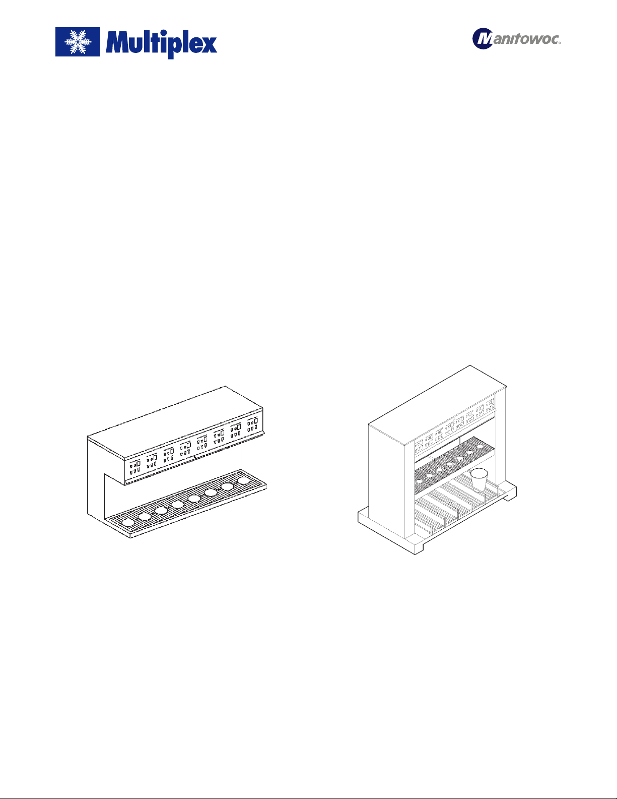
Eight Valve Front Touch Dispensing Towers and
Faucet Plates with MPC84A Portion Control
Dispensing Towers
P.N. 00914801, P.N. 00914802, P.N. 00914810,
P.N. 00914811, P.N. 00914815, P.N. 00914816,
P.N. 00914817, P.N. 00912813, P.N. 00912814,
P.N. 00912830, and P.N. 00912831
Eight Valve Pass-Thru Dispensing Towers
with MPC84A Portion Control
Dispensing Towers
P.N. 00915805, P.N. 00915806, P.N. 00915801, and
P.N. 00915811
Manitowoc Beverage Equipment
2100 Future Drive Sellersburg, IN 47172-1868
Tel: 812.246.7000, 800.367.4233 Fax: 812.246.9922
www.manitowocbeverage.com
In accordance with our policy of continuous product development and improvement,
this information is subject to change at any time without notice.
EI218843 Revision A (KAK) 10 May, 2001
Page 2

Equipment Installation Instructions
Caution: To Avoid Serious Injury
Important: Read the following warnings before beginning an installation. Failure to do so
may result in possible death or serious injury.
DO Adhere to all National and Local Plumbing and Electrical Safety Codes.
DO Turn “off” incoming electrical service switches when servicing, installing, or
repairing equipment.
DO Check that all flare fittings on the carbonation tank(s) are tight. This check
should be performed with a wrench to ensure a quality seal.
DO Inspect pressure on Regulators before starting up equipment.
DO Protect eyes when working around refrigerants.
DO Use caution when handling metal surface edges of all equipment.
DO Handle CO
2 cylinders and gauges with care. Secure cylinders properly against
abrasion.
DO Store CO2 cylinder(s) in well ventilated areas.
DO NOT Throw or drop a CO2 cylinder. Secure the cylinder(s) in an upright position
with a chain.
DO NOT Connect the CO2 cylinder(s) directly to the product container. Doing so will
result in an explosion causing possible death or injury. Best to connect the
CO2 cylinder(s) to a regulator(s).
DO NOT Store CO2 cylinders in temperature above 125°F (51.7°C) near furnaces,
radiator or sources of heat.
DO NOT Release CO2 gas from old cylinder.
DO NOT Touch Refrigeration lines inside units, some may exceed temperatures of
200°F (93.3°C).
Notice: Water pipe connections and fixtures directly connected to a potable water supply
shall be sized, installed and maintained in accordance with Federal, State, and Local codes.
2
EI218843 Revision A (KAK) 10 May, 2001
Page 3

Equipment Installation Instructions
Conversion Kit for 4-Size to 5-Size Keyboard Portion Control
on a Eight Valve Front Touch Dispensing Tower
Kit contents (P.N. 00218843)
One MPC84B 5-Size Portion Control Board (P.N. 00218380)
One 8 Valve, 5 Cup Size Keyboard (P.N. 00218840)
One 7 Pin Keyboard Harness Assembly (P.N. 00218845)
4- Tye Wraps
Installation instructions
Note: For the following procedures, refer to “Wiring Diagram
for Keyboard Kit (P.N. 00218843)”
1. Turn all power “off” to tower.
2. Remove 12 position connector from 12 pins on back right
of existing keyboard.
3. Remove 5 and 2 position connectors from 7 pins on back
left of existing keyboard.
4. Remove 10 @ 6-32 nuts from back mounting studs on existing keyboard. Remove existing 4-Size keyboard from
tower front panel.
5. Install new 5-Size keyboard (00218840) into the same
mounting holes and secure with same 6-32 nuts.
6. Re-install existing 12 pin connector onto 12 pins on back
right of new keyboard (keyed).
7. Install new harness with 7 position connector onto 7 pins
on back left of new keyboard.
Note: White wire located at pin 1.
8. Trace existing 5 and 2 wire harness back to Portion Control Board (Model MPC84B). Cut any tye wraps holding
them in place. Remove 2 position connector at J18 and 5
position connector at J17, associated with these harnesses.
Discard these harnesses.
Replacing the old Portion Control Board with new Portion
Control Board (P.N. 00218380)
1. Unplug all eight (8) valve harness connectors from portion control at J1 through J8.
2. Unplug two (2) power harness connectors from portion
control at J15 and J20.
Eight Valve Front Touch Dispensing Tower
3. Remove existing 4-Size Portion Control Board from its
standoffs.
4. Install new 5-Size Portion Control Board onto standoffs.
Extra standoffs are provided in case of breakage.
5. Plug the two (2) power harness connectors back onto new
control at J15 and J20.
6. Plug the eight (8) valve harness connectors back onto the
new control at J1 through J8, valve #1 to valve #8 respectively.
Completing installation
1. Install connectors at other end of new 7 wire harness,
5 position connector at J19 (keyed), 2 position connector
at J18 (grey on pin 1), and 5 position connector at J17
(keyed).
2. Verify new wiring and wire colors conform to schematic
drawing.
3. Supply power to tower. Verify all 5 sizes work at all Valves
and all other functions of the portion control work (refer
to “Multiplex Model MPC84B 5-Size Portion Control
Board with Top-off (P.N. 00218380)” instructions supplied).
EI218843 Revision A (KAK) 10 May, 2001
4. Clean up wiring (with supplied tye wraps) and close up
tower.
5-Size Keyboard
3
Page 4

Equipment Installation Instructions
Wiring Diagram for P.N. 00218843
Conversion Kit for 4-Size to 5-Size Keyboard Portion Control on a Eight Valve
Front Touch Dispensing Tower
4
EI218843 Revision A (KAK) 10 May, 2001
Page 5

Equipment Installation Instructions
Conversion Kit for 4-Size to 5-Size Keyboard Portion Control
on Eight Valve Pass-Thru Dispensing Tower
Kit Contents (P.N. 00218844)
One MPC84B 5-Size Portion Control Board (P.N. 00218380)
Two 8 Valve, 5 Cup Size Keyboard (P.N. 00218840)
One dual 7 Pin Keyboard Harness Assembly (P.N. 00218846)
4- Tye Wraps
Installation Instructions
Note: For the following procedures, refer to “Wiring Diagram
for Keyboard Kit (P.N. 00218844)”
1. Turn all power “off” to tower.
2. Remove 12 position connector from 12 pins on back right
of both existing tower keyboards.
3. Remove 5 and 2 position connectors from 7 pins on back
left of both existing tower keyboards.
4. Remove 10 @ 6-32 nuts from back mounting studs on both
existing keyboards.
5. Remove both existing 4-Size keyboards from tower panels.
6. Install both new 5-Size keyboards (P.N. 00218840) into the
same mounting holes and secure with same 6-32 nuts.
7. Re-install both existing 12 pin connectors onto 12 pins on
back right of new keyboards (keyed).
8. Install new harness with two (2) 7 position connectors onto
7 pins on back left of both new keyboards.
Note: White wire located at pin 1.
9. Trace both existing 5 & 2 wire harnesses back to portion
control (Model MPC84B). Cut any tye wraps holding them
in place. Remove 2 position connector at J18, and 5 position connector at J19 , associated with these harnesses.
Discard these harnesses.
Replacing the old Portion Control Board with new Portion
Control Board (P.N. 00218380)
1. Unplug all eight (8) valve harness connectors from portion control at J1 through J8.
2. Unplug two (2) power harness connectors from portion
control at J15 and J20.
3. Remove existing 4-Size Portion Control Board from its
standoffs.
Eight Valve Pass-Thru Dispensing Tower
4. Install new 5-Size Portion Control Board onto standoffs.
Extra standoffs are provided in case of breakage.
5. Plug the two (2) power harness connectors back onto new
control at J15 and J20.
6. Plug the eight (8) valve harness connectors back onto the
new control at J1 through J8, valve #1 to valve #8 respectively.
Completing installation
1. Install connectors to Portion Control Board at other end
of new 7 wire harness, 5 position connector at J19 (keyed),
2 position connector at J19 (grey on pin 1), and 5 position
connector at J19 (keyed).
2. Verify new wiring and wire colors conform to schematic
drawing.
3. Supply power to tower. Verify all 5 sizes work at all valves
and all other functions of the portion control work (refer
to “Multiplex Model MPC84B 5-Size Portion Control
Board with Top-off (P.N. 00218380)” instructions supplied).
4. Clean up wiring (with supplied tye wraps) and close up
tower.
EI218843 Revision A (KAK) 10 May, 2001
5-Size Keyboard
5
Page 6

Equipment Installation Instructions
Wiring Diagram for P.N. 00218844
Conversion Kit for 4-Size to 5-Size Keyboard Portion Control on Eight Valve
Pass-Thru Dispensing Tower
6
EI218843 Revision A (KAK) 10 May, 2001
 Loading...