

Page 1
Kit MiniMag # 21 4211
D
F
GB
I
E
© Copyright by MULTIPLEX 2006 Version 02
Bauanleitung 3-11
Notice de construction 12-20
Building instructions 21-37
Instruzioni di montaggio 38-46
Instrucciones de montaje 47-55
1
Page 2

# 21 4211
GB
Examine your kit carefully!
MULTIPLEX model kits are subject to constant quality checks throughout the production process, and we sincerely hope
that you are happy with the contents of your kit. However, we would ask you to check all the parts before you start
construction, as we cannot exchange components which you have already worked on. If you find any part is not
acceptable for any reason, we will readily correct or exchange it. Just send the component to our Model Department.
Please be sure to include a brief description of the fault.
We are constantly working on improving our models, and for this reason we must reserve the right to change the kit
contents in terms of shape or dimensions of parts, technology, materials and fittings, without prior notification. Please
understand that we cannot entertain claims against us if the kit contents do not agree in every respect with the instructions
and the illustrations.
Caution!
Radio-controlled models, and especially model aircraft, are by no means playthings. Building and operating
them safely requires a certain level of technical competence and manual skill, together with discipline and a
responsible attitude at the flying field. Errors and carelessness in building and flying the model can result in
serious personal injury and damage to property. Since we, as manufacturers, have no control over the
construction, maintenance and operation of our products, we are obliged to take this opportunity to point out
these hazards, and to emphasise your personal responsibility.
Additional items required for the Mini Mag:
Adhesive and activator Use medium-viscosity cyano-acrylate adhesive (“medium cyano”) in conjunction with activator
(“kicker”). Do not use styrofoam cyano. Epoxy glues appear to produce strong joints, but the strength is only superficial
and the hard adhesive tends to break away from the components under stress. Hot-melt glue can also be used.
MULTIPLEX radio control equipment for the Mini Mag:
PiCO 5/6 UNI receiver 35 MHz A Order No. 5 5920
alternatively: 40 MHz Order No. 5 5921
or: Micro IPD UNI receiver 35 MHz A Order No. 5 5971
alternatively: 40 MHz Order No. 5 5972
Nano S UNI or HS 55 servo (2 x required) Elevator / rudder Order No. 6 5120
and (optional):
Nano S UNI or HS 55 servo (2 x required) Ailerons Order No. 6 5120
300 mm UNI extension lead Aileron servos, 2 x Order No. 8 5031
if necessary: 200 mm UNI separation filter cable Aileron servos, 2 x Order No. 8 5035
MagicMixer #1 for 3-channel transmitter without mixers Order No. 7 3000
Y-lead (UNI) for 4-channel transmitter with separate rudder control Order No. 8 5030
MULTIcont X-16 UNI Speed controller Order No. 7 2271
MULTIPLEX Permabatt NiMH flight battery (AA cells) 7 / 1500 mAh Order No. 15 6030
or MULTIPLEX Permabatt NiMH flight battery (AA cells) 8 / 1500 mAh Order No. 15 6037
or MULTIPLEX Li-Batt (Li-Po) flight battery P-CS 2 / 1-2000 mAh Order No. 15 7016
or MULTIPLEX Li-Batt (Li-Po) flight battery SH BX 2 / 1-2100 mAh Order No. 15 7130
Battery charger:
MULTIcharger LN-5014 DC (charge current 100 mA … 5 A) 1 - 14 NiCd/ NiMH Order No. 9 2531
and 1 - 5 Li-Po cells
Optional:
Float set Order No. 73 3069
Tuning 1: Easy Glider power set (3:1 gearbox and Permax 400) Order No. 33 2688
plus 3.5 mm Ø propeller driver Order No. 33 2310
and 8 x 3.8” propeller Order No. 73 3139
Tuning 2: Powerset „sport“ BL 22/18
Contents: motor, propeller driver, speed controller, propeller Order No. 33 2627
Tools:
Scissors, balsa knife, combination pliers, cross-point / slot-head screwdrivers for servo output arm screws and motor
screws, soldering iron.
Note: please separate the illustrated pages from the centre of this booklet.
21
Page 3

Specification:
Wingspan 1010 mm
Fuselage length overall 820 mm
All-up weight min. 580 g
Wing loading (FAI) min. 26 g/dm²
Power system min. Permax 400 6V
RC functions Elevator, rudder
and throttle; optional ailerons
Important note
This model is not made of styrofoam™! It is not
possible to glue the material using white glue or
epoxy. Please be sure to use cyano-acrylate glue
exclusively, preferably in conjunction with cyano
activator (“kicker”). For all joints use medium-viscosity
cyano-acrylate (“cyano”). When gluing Elapor®
always use this procedure: spray one surface with
activator, allow it to air-dry, then apply cyano to the
other side. Join the parts and position them accurately
immediately.
Please take care when working with cyano adhesives.
These materials harden in seconds, so do not allow
them to get onto your fingers or other parts of your
body. It is important to wear goggles to protect your
eyes. Keep the adhesive out of the reach of children.
1. Before starting construction
Please check that the contents of your kit are complete.
You will find Figs. 01 + 02 and the Parts List helpful for
this.
2. Preparing the control snakes
Check the length of the elevator snake tubes 43 and 45
and shorten them if necessary.
43 3 / 2 Ø x 275 mm
45 2 / 1 Ø x 300 mm
Steel 41 0.8 Ø x 355 mm
Repeat the procedure with the rudder snake tubes 44 and
46.
44 3 / 2 Ø x 225 mm
46 2 / 1 Ø x 275 mm
Steel 42 0.8 Ø x 325 mmplease insert!
3. Installing the snakes in the fuselage shells
Caution: it is important to glue the snake outer sleeves 43
and 44 to the fuselage shells over their full length, as this
increases the strength of the tail boom considerably.
Check that the control snakes work smoothly, and be careful
not to allow any glue to run inside the outer sleeves.
4. Left-hand fuselage shell:
Trim the shell using a balsa knife, as shown in Fig. 03.
Position the snake outer sleeve 43 in the front of the fuselage
shell, as shown in Fig. 05. Lay the shell down flat, and
glue the outer sleeve 43 to the external channel over its full
length, using cyano.
Installing the servo
Set the servo to neutral (centre) from the transmitter, and
fit the output arm on the output shaft at 90° to the servo
case. Connect the pre-formed end of the steel elevator
pushrod to the second hole from the inside of the servo
output lever. Slip the inner tube 45 over the steel pushrod,
and slide both into the outer sleeve 43 from the servo end.
Fig. 05
Fit the servo in the left-hand fuselage shell from the side as
shown. If you wish to use different servos, it may be
necessary to make minor adjustments here. Tape the servo
lead in the fuselage, so that it does not get in the way
when gluing the fuselage shells together. Glue the servo to
the fuselage with a drop of hot-melt glue at each mounting
lug. Fig. 05
Glue together the wing bolt support components 33 / 34. If
finger power is not sufficient, press them together using
combination pliers, then glue the assembly in the fuselage
shell.
Place the latch clip 22 for the Canopy-Lock canopy retainer
in the fuselage in such a way that the latch lug 23 fits
between the clip 22 and the fuselage side: spray activator
in the recess in the fuselage and allow it to air-dry. Now
apply cyano to the joint surfaces of the latch clip and position
it immediately. Apply more glue to reinforce the joint if
necessary. Fig. 07
5. Option
If you wish, you can fit a tailwheel to your model. This is
actually necessary if you intend to fit floats at a later date,
as a water rudder is absolutely essential for this version,
and this uses the installed tailwheel wire. Figs. 09 - 13
show the procedure.
You will find a bending template in Figs. 12 + 12a. The
steel wire should be 1.3 mm Ø. The tube required is the
remainder of part 44. Cut the water rudder to shape from 3
mm Depron, and fix it inside the steel wire frame using
adhesive tape. Cut a V-notch in both fuselage shells to
accept the wire, as shown in Fig. 10, and pierce a hole in
the tailplane for it; Fig. 11. If you fit the tailwheel, the integral
foam tailskid on the fuselage should be cut off. Cut a slot
in the rudder for the driver wire; Fig. 10.
6. Right-hand fuselage shell:
Trim the shell using a balsa knife, as shown in Fig. 04.
Position the snake outer sleeve 44 in the front of the fuselage
shell, as shown in Fig. 06. Lay the shell down flat, and
glue the outer sleeve 44 to the outer channel over its full
length, using cyano.
Installing the servo
Set the servo to neutral (centre) from the transmitter, and
fit the output arm on the output shaft at 90° to the servo
case. Connect the pre-formed end of the steel rudder
pushrod to the innermost hole of the servo output lever.
Slip the inner tube 46 over the steel pushrod, and slide
both into the outer sleeve 44 from the servo end. Fig. 06
Glue the canopy latch clip in place; Fig. 08
7. Joining the fuselage shells
Start with the right-hand fuselage shell 4. We recommend
medium or thick cyano for this stage.
The fuselage shells 3 and 4 can now be glued together.
22
Page 4

Check that the parts fit together snugly, and carry out any
minor trimming required before reaching for the glue bottle.
Glue the wing bolt support assembly 33 / 34 in one fuselage
shell. Apply a thin coating of activator to the fuselage shell
4 and allow it to air-dry, then apply thick cyano to the mating
surfaces of the fuselage shell 3. Now join parts 3 and 4
carefully and align them quickly. The fuselage joint line must
be straight, i.e. it must not be curved!
Figs. 14 - 15
8. Installing the undercarriage support
Fit the undercarriage support 74 on the underside of the
fuselage “dry” (no glue), and press the spikes into the
fuselage material. Remove the support, then carefully apply
cyano to the joint surface on the fuselage, not forgetting
the pierced holes. Apply activator thinly to the undercarriage
support, and press it firmly into place. Fig. 16
Fit the canopy on the fuselage again, and check that it fits
neatly. Fig. 23
13. Attaching the horn to the elevator
Fit the pushrod connector 25 in the outermost hole of the
elevator horn 24, and secure it with the washer 26 and nut
27. Fig. 24
Caution: note the side on which the connector is fitted!
Tighten the nut gently until the connector swivels smoothly,
but without slop, then apply a tiny drop of cyano to the
outside of the nut on the point of a pin. Fit the socket-head
grubscrew 28 in the pushrod connector 25 using the allen
key 29; do not tighten it at this point.
Apply activator to the recess in the elevator, and glue the
prepared horn 24 in it, with the row of holes facing the hinge
line. Fig. 26
9. Preparing the motor installation
You now have to decide which power system you want to
install:
1. Standard - Permax 400, direct drive
5 x 4” Guenter or MPX propeller
Included in the kit Fig. 17
2. Standard G Permax 400 with 3:1 gearbox
Fig. 20
Easy Glider E power set
(Permax 400 with 3:1 gearbox) # 33 2688
plus 3.5 mm Ø propeller driver # 33 2310
and 8 x 3.8” propeller # 73 3139
3. “Sport” power set: BL-X 22-18 # 33 2627
The set includes the propeller driver and propeller
Attach the motor 50 to the motor mount 60 + 61. If you are
using the geared motor, cut down the motor mount 61 to a
length of 25 mm. Fig. 20
10. Connecting the motor
Carry out a test-run! The propeller must always rotate anticlockwise when viewed from the front. Reverse the motor
terminal connections if the motor spins in the wrong
direction.
11. Installing the motor
Dry-fit the motor assembly (no glue): Figs. 19 and 21;
carry out any minor adjustments required. Apply CA to the
whole surface of the motor mount and carefully fit the
assembly in the fuselage. Fig. 18
12. Installing the canopy latch lugs in the canopy
The canopy latch lugs 23 are fitted in the canopy 5 as a
mirror-image pair, i.e. with the lugs facing inward. Apply CA
to the ridged areas - in this case activator should not be
used - then push the lugs into the slots in the canopy. Fit
the canopy on the model, and allow the latch lugs to engage
in the latch clips 22. Immediately position the canopy
accurately. Allow the glue to harden for about one minute,
then carefully open the canopy again. Apply activator to
the joint areas between the latch lugs and the canopy.
Fig. 22
14. Attaching the horn to the rudder
Fit the pushrod connector 25 in the outermost hole of the
rudder horn 24, and secure it with the washer 26 and nut
27. Fig. 26
Caution: note the side on which the connector is fitted!
Tighten the nut gently until the connector swivels smoothly,
but without slop, then apply a tiny drop of cyano to the
outside of the nut on the point of a pin. Fit the socket-head
grubscrew 28 in the pushrod connector 25 using the allen
key 29; do not tighten it at this point.
Apply activator to the recess in the rudder, and glue the
prepared horn 24 in it, with the row of holes facing the hinge
line. Fig. 26
15. Freeing the elevator and rudder
Work the rudder and elevator to and fro repeatedly to free
up the hinges; they will eventually move relatively easily.
Take care not to separate the control surfaces! Figs. 25 +
27
16. Gluing the tail surfaces to the fuselage
Position the tailplane 7 on the fuselage “dry” (no glue) and
check that it fits correctly. Ensure in particular that it is
parallel to the wing saddle, and that there is no gap between
the tailplane and its mount. You can check this by laying
one of the spar tubes 40 on the wing saddle (e.g. secure it
with masking tape). Now sight over the spar from the
fuselage nose and check that the tailplane is parallel to it.
When you are confident that the tailplane can be aligned
correctly, glue it to the fuselage. Check that alignment is
correct and there are no gaps, then leave the glue to cure.
Place the fin 8 on the fuselage and tailplane “dry”, and
check it for fit. It is important here that the fin is a snug fit,
and is at 90° to the wing saddle and the tailplane; use a
setsquare or similar tool to check this.
Fig. 30
17. Retaining the elevator and rudder pushrods
Fit the front end of the steel pushrods 41 and 42 through
the pushrod connectors 25, set the servos and control
surfaces to neutral (centre) and tighten the socket-head
grubscrews 28. You may find it necessary to bend the
pushrods slightly to obtain correct alignment.
Figs. 31 - 32
23
Page 5

18. Installing the undercarriage
Fit the wheels 71 on the main undercarriage unit 70, using
two collets 72 to retain each one. Fig. 33. Squeeze the
undercarriage together gently, push it into the support 74
and allow it to snap into place. Fig. 34
Completing the wings
19. Installing the spar
Fit the spar tubes 40 in the spar joiner 31, secure them
with glue and trial-fit them in the wing. Apply cyano to the
spar channel in the wing, then push the spars and the spar
joiner quickly into place. Set the wing straight before the
adhesive has a chance to cure. Sight along the wings from
each tip to check for unwanted warps.
Fig. 35
smoothly, but without slop, then apply a tiny drop of cyano
to the outside of the nuts on the point of a pin. Fit the
socket-head grubscrews 28 in the pushrod connectors 25
using the allen key 29; do not tighten them at this point.
Apply activator to the recesses in the ailerons and glue the
horns 24 in them with the row of holes facing the hinge line.
Fig. 38
24. Installing the aileron pushrods
Connect the pre-formed end of the steel pushrods 30 to the
innermost hole of the servo output arm, and fit the plain
end through the pushrod connector 25 on the aileron horn.
Set the aileron and servo to neutral (centre), and tighten
the grubscrew 28 to secure the pushrod.
Fig. 39
Optional ailerons
If you wish to fly the model in rudder / elevator form, simply
skip points 19 - 22. The servo wells can be sealed (later)
using the decals provided.
With the standard dihedral the model flies very well with
rudder or ailerons as the primary turning control. It is also
possible to fit ailerons to the wing at any time.
If you wish to fly the model with ailerons (“full-house” control),
resume construction at this point:
20. Freeing the ailerons, installing the aileron servos
Cut a slot at both ends of the ailerons, which are attached
to the wing 6. Work the ailerons to and fro repeatedly to
free up the hinges; they will eventually move relatively easily.
Take care not to separate the control surfaces!
Fig. 36
21. Installing the aileron servos
Set the servos to neutral from the transmitter. Fit the output
arms on the servos so that the arms are at 90° to the servo
case - 1 x left, 1 x right.
Check that the servos fit snugly in the recesses in the
wings 6. You may need to make minor adjustments to suit
the servo type you are using. Apply a drop of hot-melt glue
to the slots in the wing for the servo mountings lugs, and
press the servos into the recess immediately. Apply another
drop of glue if necessary.
Fig. 37
22. Deploying the aileron servo leads
Deploy the servo leads along the wing towards the centre
section. The lead must fit in the front edge of the spar
channel and run perfectly straight, standing “on edge”. The
leads should project by about 120 mm at the wing root, so
that you can comfortably connect the plugs to the receiver
when the model is assembled. You may need to extend
the standard servo leads. Secure the leads at the centre of
the wings with a drop of hot-melt glue.
23. Attaching the aileron horns
Fit the pushrod connectors 25 in the outermost hole of the
aileron horns 24. Secure the connectors using the washers
26 and nuts 27. Caution: make a handed pair: 1 x left, 1 x
right. Tighten the nuts gently until the connectors swivel
25. Attach the wing to the fuselage using the screw 32.
Fig. 40
26. Installing the radio control system components
The next step is to install the remaining radio components
and the flight battery in the cabin area. Keep one eye on
the recommended Centre of Gravity position when
positioning these items; see Fig. 43.
You can correct the CG position by adjusting the location
of the flight battery.
Pieces of Velcro tape 20 + 21 are supplied in the kit for
securing these components. Please note that the adhesive
on the tape is not very strong, and we recommend that you
stick the tape in the fuselage with cyano for additional
security.
Fit the receiver behind the wing screw, standing upright.
Run the aerial wire out of the fuselage and tape it in place.
The speed controller should be positioned immediately aft
of the motor.
The motor supplied in the kit features internal suppressors,
and these are adequate if you are using a MULTIcont X-16
speed controller, # 7 2271.
If you prefer to use a different controller, it is in your own
interests to fit additional suppression measures to the
electric motor. A suitable suppressor set is available under
# 8 5020. Solder one 47 nF capacitor between one motor
terminal and the motor can, and a second one between the
other terminal and the can. The third 47 nF capacitor should
be soldered across the terminals to form a bridge.
Installing the propeller
The next step is the initial test-run of the motor, but first the
propeller must be fitted. The procedure for this varies
according to the power system you have installed. However,
please be sure it is firmly located in every case. In the
standard version the spinner and propeller should be
secured with a drop of adhesive and glued to the motor
shaft. Use 5-minute epoxy with a Guenter propeller, and
cyano with an MPX prop.
Once the wiring is complete, you are ready to carry out the
first test-run.
24
Page 6
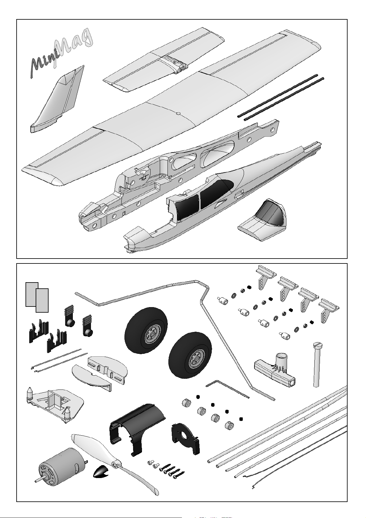
7
# 21 4211
8
6.
2 x 40
4
3
5
2 x 20
2 x 22
2 x 21
74
2 x 23
2 x 30
33
70
34
61
Abb. 01
4 x 24
4 x
25 26 27 28
2 x 71
32
29
31
4 x 73
50
52
2 x 62
4 x 63
60
4 x 72
43 44 45 46 41 42
Abb. 02
25
Page 7

3
4
41
45
22
43
20 mm
Hot
glue
CA
Abb03
CA
Abb. 05
Hot
glue
42
46
44
20 mm
22
Abb. 04
CA
Abb. 06
CA
Ø 26
# 73 3199
Heckrad=Option. Die Teile
liegen dem BK nicht bei!
Tailwheel = option. Parts not
included in the kit
26
Abb. 07
Depron
Abb.09
30
Abb. 08
8
CA
Abb.10
Page 8

Stahl/Steel
Ø 1,3 mm
Rest von Teil 44
7
4
PVC Rohr 2/3 mm
Remainder of part
44; 2/3 mm Ø
PVC tube
Stahl/Steel
Ø 1,3 mm
Abb. 11
M 1:1
Stahl/Steel
Ø 1,3 mm
Depron
3 mm
Abb. 12
Das Teil liegt dem BK nicht bei!
This part not included in the kit
Abb. 12 a
Abb. 13
33 - 34
M 1:1
Die Teile liegen dem BK nicht bei!
These parts not included in the kit
Abb. 13 a
74
CA
4
Abb. 14
27
Page 9

CA
CA
MPX-Prop.
Abb. 15
52 60 50 61
2 x 62
4 x 63
Abb. 17
Abb.16
CA
Abb. 18
Mitnehmer
für Ø 3,5 mm /
3.5 mm Ø driver
# 33 2310
passende Luftschraube / propeller
8 x 3,8“
# 73 3139
28
Abb. 19
Abb.21
# 33 2688
(Antrieb / motor Easy Glider E)
30
23
Abb. 20
CA
5
Abb.22
Page 10

28 25 24 26 27
5
7
Abb. 23
7
27 26 24 25 28
CA
CA
Abb.24
gängig machen!
Move to and fro to ease hinge
8
gängig machen!
Move to and fro to ease hinge
Abb. 25
Abb. 27
8
Abb. 26
CA
Abb. 28
30
CA
!
Abb.29
Abb.30
29
Page 11

Abb. 31
Abb. 32
70
72
40
73
71
31
72
73
Abb. 33
CA
40
74
Abb. 34
Abb. 36
Abb. 35
30
Hot
glue
Abb.37
30
6.
28 25 24 26 27
CA
Abb. 38
Page 12

Abb. 39
32
Abb.40
Abb. 41
# 73 3069
Schwimmerbausatz/Float kit
Abb. 42
Abb.43
31
Page 13

Ersatzteile (bitte bei Ihrem Fachhändler bestellen)
Replacement parts (please order from your model shop)
Pièces de rechanges (S.V.P. à ne commander que chez votre revendeur)
Parti di ricambio (da ordinare presso il rivenditore)
Repuestos (por favor, diríjase a su distribuidor)
# 22 4176
Kabinenhaube
Canopy
Verrière
Capottina
Cabina
# 22 4179
Kleinteilesatz
Small items set
Petit nécessaire
Minuteria
Piezas pequeñas
# 22 4175
Rumpfhälften + Bowdenzüge
Fuselage shells + snakes
Moitié de fuselage + tringlerie
Semigusci fusoliera + bowden
Fuselaje + trans. bowden
# 22 4178
Leitwerkssatz
Tail set
Kit de gouvernes
Piani di coda
Timones
# 22 4177
Tragfläche
panel
Aile
Ali
Alas
# 72 4388
Dekorbogen
Decal sheet
Planche de décoration
Decals
Lámina decorativa
# 22 4180
Fahrwerkssatz
Undercarriage compon.
Train d’atterrissage
Parti per carrello
Kit del tren de aterrizaje
# 70 3455
Gestängeanschluss (2x)
Pushrod connector (2x)
Element de fixitation (2x)
Raccordo rinvii (2x)
Conexión del verillaje(2x)
# 33 2545
Motor
Motor
Moteur
Motore
Motor
# 33 2699
Motorträger
Motor mount
Support moteur
Supporto motore
Soporte del motor
# 72 5136
Canopy-Lock
Kabinenhaubenverschluss
Fermeture de verrière
Chiusura capottina
Cierre de cabina
Permax 400 6V
# 72 4279 / # 72 4293
Luftschraube
Propeller
Hélice
Elica
Hélice
32
# 71 3340
Schraube M5x50mm (10x)
Screw M5x50mm (10x)
Vis M5x50mm (10x)
Vite M5x50mm (10x)
Tornillo M5x50mm (10x)
5,0x4,0" / 12,7x10,2cm
Page 14

Do not connect the flight battery to the speed controller
until you have switched on the transmitter and move
the throttle stick or switch to the “Motor Stopped”
position.
Switch on the transmitter, connect the flight battery to the
speed controller, and the controller to the receiver. With
this model you must use a controller with what is known
as a BEC circuit (receiver power supply from the flight
battery).
Now switch the motor on briefly, and check once more the
direction of rotation of the propeller. Hold the model firmly
when you run the motor, and remove any loose lightweight
objects from the area behind the model before the propeller
does the job for you.
Caution: even small motors and propellers represent
a distinct injury hazard!
27. Setting the control surface travels
It is important to set the control surface travels correctly,
as these settings have a crucial influence on the model’s
overall control response. In all cases the travels are
measured at the point of maximum chord (width of control
surface.
Elevator
up - stick back - approx. + 11 mm
down - stick forward - approx. - 11 mm
Rudder
left and right - approx. 6-10 mm
each way
Ailerons
up - approx. + 7 mm
down - approx. - 3 mm
MagicMixer #1 (optional) # 7 3000
The MagicMixer #1 permits the use of a simple radio control
transmitter without mixer functions. It is adequate for:
MINI MAG 3-channel RC transmitter
Without the MagicMixer #1 you will need at least a fourchannel computer transmitter with mixer functions.
Using this module the Mini Mag can be flown even with a
transmitter such as the Ranger III, as supplied with the
EasyStar and SpaceScooter RTF models.
It provides a means of controlling two aileron servos and
the rudder from a single channel (right / left output) at the
receiver.
The servos, and therefore the control surface travels, are
automatically actuated with the correct deflections. Using
the MagicMixer #1 the degree to which the rudder follows
the ailerons (“combi-switch” / CAR function) and the aileron
differential are fixed, i.e. they cannot be altered.
Aileron differential means that the up-aileron travel is greater
than the down-aileron travel. This helps to prevent the model
swinging away from the turn (adverse yaw) when ailerons
are applied.
If you are using the MagicMixer #1 your transmitter must
offer at least the following channels:
Channel 1: Ailerons, coupled rudder (3 servos)
Channel 2: Elevator (1 servo)
Channel 3: Throttle (1 servo)
Connect the aileron servo leads as described in the
“MagicMixer #1” instructions. Take care to maintain
correct polarity when making these connections: the signal
pin is indicated on the label of the MagicMixer with the
square signal symbol. The signal wire in the servo lead is
generally yellow or orange.
Connections at the MagicMixer #1:
r/l = to receiver, right / left output
AR = to right aileron servo
AL = to left aileron servo
R = to rudder servo
If necessary, set the correct direction of servo travel using
the servo reverse facility on your transmitter.
Y-lead for the aileron servos (optional) # 8 5030
The Y-lead permits the use of a simple four-channel radio
control transmitter, i.e. without mixer functions. The two
aileron servos are actuated simultaneously by a single
receiver servo output.
Please note: in this case the differential aileron movement
must be obtained by mechanical means. This is achieved
by offsetting the servo output arms forward by two splines.
This must be done before you install the servos. The rudder
is controlled via a separate channel with this arrangement.
Computer radio control transmitter
If you have this type of transmitter you need neither a
MagicMixer #1 nor a Y-lead.
The transmitter must feature the following adjustment
facilities:
- Aileron differential mixer
- Servo reverse
- Servo travel adjustment
- Optional combi-switch (coupled rudder / ailerons)
Note: when you apply a right-aileron command at the
transmitter, the right-hand aileron (as seen from the
tail) must deflect up.
If you find that you cannot set the correct control
surface travels with your radio control system, you
will need to change the linkage hole to which the
pushrod is connected.
28. Gilding the lily
The kit includes a multi-colour decal sheet. Cut out the
individual name placards and emblems and apply them to
the model, either following our scheme (kit box illustration)
or using your own arrangement. If you have built the rudder
/ elevator version of the model, you will find decals on the
sheet designed for covering the servo recesses in the wing.
33
Page 15

29. Balancing
If your Mini Mag is to fly safely and stably it must balance
at the correct point - just like every other aircraft. Assemble
your model completely, ready to fly, and install the flight
battery.
Don’t attempt tightly banked turns close to the ground at
first, and especially not on the landing approach.
It is always better to land safely some distance away, and
have to walk to collect the model, than to risk damaging it
by dragging it close to your feet.
The Centre of Gravity should be at a point 67 mm aft of
the leading edge of the wing, measured where the wing
meets the fuselage. You will find markings moulded into
the underside of the wing at this point.
Support the model on your fingertips at the marked point,
and it should balance level. If necessary, adjust the position
of the flight battery until this is the case. Once the correct
position is found, mark it inside the battery box to ensure
that the battery is always replaced in exactly the same
location. Fig. 43
30. Preparing for the first flight
Wait for a day with as little breeze as possible for the first
flight. The evening hours often provide the best conditions.
Be sure to carry out a range check before the first
flight!
The transmitter battery and flight pack must be fully charged
according to the instructions. Ensure that the channel you
are using is not already in use before you switch on the
transmitter.
Collapse the transmitter aerial, and ask a friend to walk
away from you holding the transmitter.
As he walks away your friend should constantly operate
one control function while you watch the model’s servos.
The servo not being operated should stay motionless up to
a range of around 60 m, and the other servo should follow
the transmitter stick movements smoothly and immediately.
This test only provides meaningful results if the radio band
is “clean” (not suffering interference), and if no other radio
control transmitters are switched on, even if they are on
different channels. If successful, repeat the check with
the motor running. The effective range should not be
significantly reduced when the motor is running.
If you are not sure about anything, do not fly the model! If
you cannot eliminate the problem send the whole radio
control system (including battery, switch harness, servos)
to the manufacturer’s service department for checking.
31. Safety
Safety is the First Commandment when flying any model
aircraft. Third party insurance should be considered a basic
essential. If you join a model club suitable cover will usually
be available through the organisation. It is your personal
responsibility to ensure that your insurance is adequate
(i.e. that its cover includes powered model aircraft).
Make it your job to keep your models and your radio control
system in perfect order at all times. Check the correct
charging procedure for the rechargeable batteries used in
your RC set. Make use of all sensible safety systems and
precautions which are advised for your system. An excellent
source of practical accessories is the MULTIPLEX main
catalogue, as our products are designed and manufactured
exclusively by practising modellers for other practising
modellers.
Always fly with a responsible attitude. You may think that
flying low over other people’s heads is proof of your piloting
skill; others know better. The real expert does not need to
prove himself in such childish ways. It is in all our interests
that you let other pilots know that this is also what you
think. Always fly in such a way that you do not endanger
yourself or others. Bear in mind that even the best RC
system in the world is subject to outside interference. No
matter how many years of accident-free flying you have
under your belt, you have no idea what will happen in the
next minute.
We - the MULTIPLEX team - hope you have many hours of
pleasure building and flying your new model.
Klaus Michler
Product development
MULTIPLEX Modellsport GmbH & Co. KG
The first flight ....
Do not test-glide this model!
The model is designed for hand-launching - always exactly
into wind.
We recommend that you ask an experienced
modeller to help you during the first flight.
Allow the model to climb to a safe altitude, then adjust the
trims on the transmitter so that the model flies straight
ahead without any help from you.
At a safe height switch off the motor and make yourself
familiar with the model’s control response on the glide. Carry
out a dummy landing approach at a good height, so that
you will feel confident about the real landing when the flight
pack is flat.
34
Page 16

Parts List Mini Mag kit # 21 4211
Part No. off Description Material Dimensions
1 1 Building instructions Paper A4
2 1 Decal sheet Printed adhesive film 400 x 700 mm
3 1 Left-hand fuselage shell Moulded Elapor foam Ready made
4 1 Right-hand fuselage shell Moulded Elapor foam Ready made
5 1 Canopy Moulded Elapor foam Ready made
6 1 Wing Moulded Elapor foam Ready made
7 1 Tailplane Moulded Elapor foam Ready made
8 1 Fin Moulded Elapor foam Ready made
Small parts set
20 2 Velcro tape, hook Plastic 25 x 60 mm
21 2 Velcro tape, loop Plastic 25 x 60 mm
22 2 Canopy latch clip Inj. moulded plastic Ready made
23 2 Canopy latch lug Inj. moulded plastic Ready made
24 4 Glue-fitting horn Inj. moulded plastic Ready made
25 4 Pushrod connector Metal Ready made, 6 mm Ø
26 4 Washer Metal M2
27 4 Nut Metal M2
28 4 Socket-head grubscrew Metal M3 x 3 mm
29 2 Allen key Metal 1.5 mm A/F
30 2 Aileron pushrod, one Z-bend Metal 1 Ø x 70
31 1 Spar joiner Inj. moulded plastic Ready made
32 1 Screw Plastic M5 x 50 mm
33 1 Wing bolt support A Inj. moulded plastic Ready made, M5
34 1 Wing bolt support B Inj. moulded plastic Ready made, M5
Wire set
40 2 Spar tube GRP tube 6 / 4 Ø x 300 mm
41 1 Steel elevator pushrod, one Z-bend Metal 0.8 Ø x 355 mm
42 2 Steel rudder pushrod, one Z-bend Metal 0.8 Ø x 325 mm
43 1 Elevator snake outer sleeve Plastic 3 / 2 Ø x 275 mm
44 1 Rudder snake outer sleeve Plastic 3 / 2 Ø x 225 mm (275 mm*)
45 1 Elevator snake inner tube Plastic 2 / 1 Ø x 300 mm
46 1 Rudder snake inner tube Plastic 2 / 1 Ø x 275 mm (300 mm*)
*supplied length -> cut to correct length
Power set
60-63 1 Motor mount, Permax 400 (1 off) See below
50 1 Motor Permax 400 6 V Ready made
52 1 Propeller Plastic 125 x 110 mm
Permax 400 motor mount (1 x), two-part incl. screws
60 1 Motor bulkhead Inj. moulded plastic Ready made
61 1 Motor bulkhead holder Inj. moulded plastic Ready made
62 2 Screw Metal M2.5 x 4 mm
63 4 Screw Metal 2.2 x 13 mm
Undercarriage set
70 1 Main undercarriage unit Metal 2.5 Ø, ready made
71 2 Lightweight wheel Plastic 53 Ø, 2.5 mm bore
72 4 Collet Metal 2.7 / 7 Ø x 5 mm
73 4 Socket-head grubscrew Metal M3 x 3 mm
74 1 Undercarriage support Plastic Ready made
CD instructions / movie
80 1 CD instructions / movie Ready made
35
Page 17

Basic information relating to model aircraft
Any aircraft, whether full-size or model, can be controlled around the three primary axes: vertical (yaw), lateral (pitch) and
longitudinal (roll).
When you operate the elevator, the model’s attitude alters around the lateral axis. If you apply a rudder command, the model
swings around the vertical axis. If you move the aileron stick, the model rolls around its longitudinal axis. As our EasyStar has
considerable wing dihedral, ailerons are not required for roll control. In this case the rudder is used both to turn the model
around the vertical axis, and also to roll it (longitudinal axis). External influences such as air turbulence may cause the model to
deviate from its intended flight path, and when this happens the pilot must control the model in such a way that it returns to the
required direction. The basic method of controlling the model’s height (altitude) is to vary motor speed (motor and propeller). The
rotational speed of the motor is usually altered by means of a speed controller. Applying up-elevator also causes the model to
gain height, but at the same time it loses speed, and this can only be continued until the model reaches its minimum airspeed
and stalls. The maximum climb angle varies according to the power available from the motor.
R.H. wing
panel
normal axis
Canopy
Longitudinal axis
Wing section
The wing features a cambered airfoil section over which the
air flows when the model is flying. In a given period of time the
air flowing over the top surface of the wing has to cover a
greater distance than the air flowing under it. This causes a
reduction in pressure on the top surface, which in turn creates
a lifting force which keeps the aircraft in the air. Fig. A
Centre of Gravity (CG)
To achieve stable flying characteristics your model aircraft must
balance at a particular point, just like any other aircraft. It is
absolutely essential to check and set the correct CG position
before flying the model for the first time.
The CG position is stated as a distance which is measured aft
from the wing root leading edge, i.e. close to the fuselage.
Support the model at this point on two fingertips (or - better use the MPX CG gauge, # 69 3054); the model should now
hang level. Fig. B
If the model does not balance level, the installed components
(e.g. flight battery) can be re-positioned inside the fuselage. If
this is still not sufficient, attach the appropriate quantity of trim
ballast (lead or plasticene) to the fuselage nose or tail and
secure it carefully. If the model is tail-heavy, fix the ballast at the
fuselage nose; if the model is tail-heavy, attach the ballast at
the tail end of the fuselage.
The longitudinal dihedral is the difference in degrees between
the angle of incidence of the wing and of the tail. Provided that
you work carefully and attach the wing and tailplane to the
fuselage without gaps, the longitudinal dihedral will be correct
automatically.
Fin
Tailplane
Rudder
Elevator
lateral axis
L.H. wing
Fuselage
panel
GB
If you are sure that both these settings (CG and longitudinal
dihedral) are correct, you can be confident that there will be no
major problems when you test-fly the model. Fig. C
Control surfaces, control surface travels
The model will only fly safely, reliably and accurately if the control
surfaces move freely and smoothly, follow the stick movements
in the correct “sense”, and move to the stated maximum travels.
The travels stated in these instructions have been established
during the test-flying programme, and we strongly recommend
that you keep to them initially. You can always adjust them to
meet your personal preferences later on.
Transmitter controls
The transmitter features two main sticks which the pilot moves
to control the servos in the model, which in turn operate the
control surfaces.
The functions are assigned according to Mode A, although
other stick modes are possible.
The transmitter controls the control surfaces as follows:
Rudder (left / right) Fig. D
Elevator (up / down) Fig. E
Throttle (motor off / on) Fig. F
Unlike the other controls, the throttle stick must not return to
the neutral position automatically. Instead it features a ratchet
so that it stays wherever you put it. Please read the instructions
supplied with your radio control system for the method of setting
up and adjusting the transmitter and receiving system.
36
Page 18

MULTIPLEX Modellsport GmbH & Co.KG Neuer Weg 2 D-75223 Niefern-Öschelbronn www.multiplex-rc.de
56
 Loading...