

Page 1
Beverage Conduit
Beer & Soda
Installation, Use & Care Manual
This manual is updated as new information and models are released.
Visit our website for the latest manual. www.manitowocfsg.com
America’s Quality Choice in Refrigeration
Part Number EI211017 10/11
Page 2
Safety Notices
!
Warning
!
Caution
Important
!
Caution
Important
!
Warning
As you work on Manitowoc equipment, be sure to pay
close attention to the safety notices in this manual.
Disregarding the notices may lead to serious injury and/
or damage to the equipment.
Throughout this manual, you will see the following types
of safety notices:
Text in a Warning box alerts you to a potential
personal injury situation. Be sure to read the
Warning statement before proceeding, and work
carefully.
Text in a Caution box alerts you to a situation in
which you could damage the equip ment. Be sure to
read the Caution statement before proceeding, and
work carefully.
Procedural Notices
As you work on Manitowoc equipment, be sure to read
the procedural notices in this manual. These notices
supply helpful information which may assist you as you
work.
Throughout this manual, you will see the following types
of procedural notices:
Read These Before Proceeding:
Proper installation, care and maintenance are
essential for maximum performance and trouble-free
operation of your Manitowoc equipment. Read and
understand this manual. It contains valuable care
and maintenance information. If you encounter
problems not covered by this manual, do not
proceed, contact Manitowoc. We will be happy to
provide assistance.
Routine adjustments and maintenance procedures
outlined in this manual are not covered by the
warranty.
PERSONAL INJURY POTENTIAL
Do not operate equipment that has been misused,
abused, neglected, damaged, or altered/modified
from that of original manufactured specifications.
NOTE: SAVE THESE INSTRUCTIONS.
Text in an Important box provides you with
information that may help you perform a procedure
more efficiently. Disregarding this information will not
cause damage or injury, but it may slow you down as
you work.
NOTE: Text set off as a Note provides you with simple,
but useful, extra information about th e pr oce dur e yo u
are performing.
We reserve the right to make product improvements at any time.
Specifications and design are subject to change without notice.
Page 3

Section 1
General Information
Section 2
Installation
Table of Contents
Read This Manual. . . . . . . . . . . . . . . . . . . . . . . . . . . . . . . . . . . . . . . . . . . . . . . . . 1-1
Unit Inspection . . . . . . . . . . . . . . . . . . . . . . . . . . . . . . . . . . . . . . . . . . . . . . . . . . . 1-1
Model Numbers. . . . . . . . . . . . . . . . . . . . . . . . . . . . . . . . . . . . . . . . . . . . . . . . . . . 1-1
Flame & Smoke Rating. . . . . . . . . . . . . . . . . . . . . . . . . . . . . . . . . . . . . . . . . . . . . 1-2
Specification Compliance . . . . . . . . . . . . . . . . . . . . . . . . . . . . . . . . . . . . . . . . . . 1-2
Warranty Information . . . . . . . . . . . . . . . . . . . . . . . . . . . . . . . . . . . . . . . . . . . . . . 1-2
Shipping, Storage, & Relocation. . . . . . . . . . . . . . . . . . . . . . . . . . . . . . . . . . . . . 1-2
Pre-installation . . . . . . . . . . . . . . . . . . . . . . . . . . . . . . . . . . . . . . . . . . . . . . . . . . . 2-1
REQUIRED TOOLS . . . . . . . . . . . . . . . . . . . . . . . . . . . . . . . . . . . . . . . . . . 2-1
UNPACKING & INSPECTING . . . . . . . . . . . . . . . . . . . . . . . . . . . . . . . . . . 2-1
Location Requirements . . . . . . . . . . . . . . . . . . . . . . . . . . . . . . . . . . . . . . . . 2-1
Kitchen Equipment Installer Representative Responsibilities . . . . . . . . . . . 2-1
Other Requirements . . . . . . . . . . . . . . . . . . . . . . . . . . . . . . . . . . . . . . . . . . 2-1
Installer Instructions . . . . . . . . . . . . . . . . . . . . . . . . . . . . . . . . . . . . . . . . . . . . . . 2-1
Routing Multiplex Conduit. . . . . . . . . . . . . . . . . . . . . . . . . . . . . . . . . . . . . . . . . . 2-2
FLOOR CHASES . . . . . . . . . . . . . . . . . . . . . . . . . . . . . . . . . . . . . . . . . . . . 2-2
Sealing Instructions . . . . . . . . . . . . . . . . . . . . . . . . . . . . . . . . . . . . . . . . . . . 2-2
OVERHEAD INSTALLATION . . . . . . . . . . . . . . . . . . . . . . . . . . . . . . . . . . . 2-3
How To Connect The Multiplex Conduit. . . . . . . . . . . . . . . . . . . . . . . . . . . . . . . 2-4
Conduit Identification Chart . . . . . . . . . . . . . . . . . . . . . . . . . . . . . . . . . . . . . 2-5
COLOR AND NUMBER CODING . . . . . . . . . . . . . . . . . . . . . . . . . . . . . . . . 2-5
Fittings . . . . . . . . . . . . . . . . . . . . . . . . . . . . . . . . . . . . . . . . . . . . . . . . . . . . 2-7
TEEING INTO MULTIPLEX CONDUIT SODA SYSTEMS . . . . . . . . . . . . . 2-7
Soda Conduit Kit Diagrams . . . . . . . . . . . . . . . . . . . . . . . . . . . . . . . . . . . . . 2-9
Beermaster Beer Conduit . . . . . . . . . . . . . . . . . . . . . . . . . . . . . . . . . . . . . . . . . . 2-10
INTRODUCTION . . . . . . . . . . . . . . . . . . . . . . . . . . . . . . . . . . . . . . . . . . . . 2-10
FLOOR CHASES . . . . . . . . . . . . . . . . . . . . . . . . . . . . . . . . . . . . . . . . . . . . 2-10
OVERHEAD INSTALLATION . . . . . . . . . . . . . . . . . . . . . . . . . . . . . . . . . . . 2-11
BASEMENT CONSTRUCTION . . . . . . . . . . . . . . . . . . . . . . . . . . . . . . . . . 2-11
Connecting Beer Conduit . . . . . . . . . . . . . . . . . . . . . . . . . . . . . . . . . . . . . . . . . . 2-12
Part Number EI211017 10/11 i
Page 4

Section 3
Operation
Section 4
Maintenance
Table of Contents (continued)
Beermaster Conduit Kit . . . . . . . . . . . . . . . . . . . . . . . . . . . . . . . . . . . . . . . . . . . . 2-13
General . . . . . . . . . . . . . . . . . . . . . . . . . . . . . . . . . . . . . . . . . . . . . . . . . . . . 2-13
Beermaster Conduit Kit Diagrams . . . . . . . . . . . . . . . . . . . . . . . . . . . . . . . . 2-14
INSTALLING THE CONDUIT KIT . . . . . . . . . . . . . . . . . . . . . . . . . . . . . . . . 2-15
Connections . . . . . . . . . . . . . . . . . . . . . . . . . . . . . . . . . . . . . . . . . . . . . . . . . 2-15
BEER RESTRICTOR LINES . . . . . . . . . . . . . . . . . . . . . . . . . . . . . . . . . . . . 2-16
Maintenance Schedule . . . . . . . . . . . . . . . . . . . . . . . . . . . . . . . . . . . . . . . . . . . . . 4-1
Periodic Maintenance Listed By Major Components . . . . . . . . . . . . . . . . . . 4-1
Periodic Maintenance Listed By Scheduled Frequency . . . . . . . . . . . . . . . 4-2
Cleaning & Sanitizing The Dispensing Valves & Product Lines . . . . . . . . . 4-3
Cleaning Equipment and Supplies . . . . . . . . . . . . . . . . . . . . . . . . . . . . . . . . . . . 4-3
Sanitizing . . . . . . . . . . . . . . . . . . . . . . . . . . . . . . . . . . . . . . . . . . . . . . . . . . . . . . . . 4-3
Beverage System Cleaning . . . . . . . . . . . . . . . . . . . . . . . . . . . . . . . . . . . . . 4-3
Bag-In-Box System Sanitation . . . . . . . . . . . . . . . . . . . . . . . . . . . . . . . . . . . 4-4
Figal Beverage System . . . . . . . . . . . . . . . . . . . . . . . . . . . . . . . . . . . . . . . . 4-5
Shipping, Storage and Relocation. . . . . . . . . . . . . . . . . . . . . . . . . . . . . . . . . . . . 4-5
Section 5
Before Calling for Service
Checklist . . . . . . . . . . . . . . . . . . . . . . . . . . . . . . . . . . . . . . . . . . . . . . . . . . . . . . . . 5-1
Soda Systems . . . . . . . . . . . . . . . . . . . . . . . . . . . . . . . . . . . . . . . . . . . . . . . 5-1
No syrup or insufficient syrup in finished drink . . . . . . . . . . . . . . . . . . . . . . 5-1
No carbonated water or insufficient carbonated water in finished drink . . . 5-2
No water or insufficient water in finished drinks . . . . . . . . . . . . . . . . . . . . . 5-2
Beermaster Systems . . . . . . . . . . . . . . . . . . . . . . . . . . . . . . . . . . . . . . . . . . 5-5
ii Part Number EI211017 10/11
Page 5
Section 1
!
Warning
!
Caution
General Information
Read This Manual
Manitowoc Beverage Systems developed this manual as
a reference guide for the owner/operator and installer of
this equipment. Please read this manual before
installation or operation of the machine. A qualified
service technician must perform installation and start-up
of this equipment.
If you cannot correct the service problem, call your
Manitowoc Beverage Systems (MBS) Service Agent or
Distributor. Always have your model and serial number
available when you call.
Your Service Agent ____________________________
Service Agent Telephone Number_________________
Your Local MBE Distributor ______________________
Distributor Telephone Number____________________
Model Number _______________________________
Serial Number ________________________________
Installation Date ______________________________
Unit Inspection
Thoroughly inspect the unit upon delivery. Immediately
report any damage that occurred during tr ansportation to
the delivery carrier. Request a written inspection report
from a claims inspector to document any necessary
claim.
PERSONAL INJURY POTENTIAL
Do not operate equipment that has been misused,
abused, neglected, damaged, or altered/modified
from that of original manufactured specifications.
Model Numbers
This manual covers the following models:
Beverage Conduit Models
MC095301, MC105301, MC105511, MC105521, MC105581,
MC125311, MC125511, MC125581, MC133301, MC135321,
MC145511, MC145351, MC145521, MC145551, MC165322,
MC175201, MC205501, MC205301, MC205311, MC245301,
MC245501, MC023341, MC043341, MC063341, MC073341,
MC083341, MC103341, MC123341, MC143341, MC163341,
MC193341, MC203341, MC043342, MC053342, MC063342,
MC073342, MC083342, MC103342, MC123342, MC143342,
MC163342, MC193342, MC203342
To Avoid Serious Injury: Read the following
warnings before beginning an installation. Failure to
do so may result in possible death or serious injury.
DO Adhere to all National and Local Plumbing and
Electrical Safety Codes.
DO Turn “off” incoming electrical service switches
when servicing, installing, or repairing
equipment.
DO Check that all flare fittings are tight. This check
should be performed with a wrench to ensure a
quality seal.
DO Inspect pressure on Regulators before starting
up equipment.
DO Protect eyes when working around
refrigerants.
DO Use caution when handling metal surface
edges of all equipment.
DO Handle CO
2 cylinders and gauges with care.
Secure cylinders properly against abrasion .
DO Store CO
DO NOT Exhaust CO
2 cylinder(s) in well ventilated areas.
2 gas (example: beer pump)
into an enclosed area, including all types of
walk in coolers, cellars, and closets.
DO NOT Throw or drop a CO
2 cylinder. Secure the
cylinder(s) in an upright position with a chain.
DO NOT Connect the CO
2 cylinder(s) directly to the
product container. Doing so will result in an
explosion causing possible death or injury.
Best to connect the CO
2 cylinder(s) to a
regulator(s).
DO NOT Sto re C O
2 cylinders in temperature above
125°F (51.7°C) near furnaces, radiator or
sources of heat.
DO NOT Release CO
2 gas from old cylinder.
DO NOT Touch Refrigeration lines inside units, some
may exceed temperatures of 200°F (93.3°C).
NOTE: All utility connections and fixtures shall be sized,
installed and maintained in accordance with Federal,
State, an d Local codes.
Part Number EI211017 10/11 1-1
Page 6

General Information Section 1
Flame & Smoke Rating
INSUL-TUBE® Pipe Insulation in wall thickness of 1" (25
mm) and below has a flame spread rating of 25 or less
and a smoke development rating of 50 or less as tested
by ASTM E 84 Method of Testing entitled: Surface
Burning Characteristics of Building Materials. Duct/
Plenum Applications INSUL-TUBE® is acceptable for
duct/plenum applications, meeting requirements of
NFPA 90A.
Numerical flammability ratings alone may not define the
performance of products under actual fire conditions.
They are provided only for use in the selection of
products to meet limits specified, when compared to a
known standard.
Specification Compliance
• ASTM C 534 Type 1 (Tubing)
• ASTM D 1056-00-2C1
• ASTM C 1534-02
• New York City MEA 186-86-M Vol. IV
• USDA Requirements
• UL 94-5V Flammability Classification (Recognition
No. E147665)
• ASTM E 84 1" 25/50-tested according to UL 723 and
NFPA 255
• Complies with requirements of CAN/ULC S102-M88
Warranty Information
Consult your local MBS Distributor for terms and
conditions of your warranty. Your warranty specifically
excludes all beverage valve brixing, general
adjustments, cleaning, accessories and related
servicing.
Your warranty card must be returned to MBS to activate
the warranty on this equipment. If a warranty card is not
returned, the warranty period can begin when the
equipment leaves the MBE factory.
No equipment may be returned to MBS without a written
Return Materials Authorization (RMA). Equipment
returned without an RMA will be refused at the MBS
dock and returned to the sender at the sender’s
expense.
Please contact your local MBS distributor for return
procedures.
Shipping, Storage, & Relocation
Store conduit in 60°F (15.5°C) to 80°F (16.6°C)
environment.
- Keep in a cool, dry location.
- Do not expose to direct sunlight.
- Do not store conduit outside the original carton.
- Do not store conduit for more than one year.
- Do not store anything directly on top of conduit.
• NFPA No. 101 Class A Rating
• Meets requirements of NFPA 90A Sect. 2.3.3 for
Supplementary Materials for Air Distribution
Systems.
• Meets requirements of ASTM C 411 (Tested Method
of Hot Surface Performance of High Temperature
Thermal Insulation).
• Meets requirements of UL 181 sections 11.0 and
16.0 (Mold Growth/Air Erosion)
• MIL-P-15280, For T (Tubing)
- Do not store in an enclosed location with high
aromatic compounds.
- Conduit warranty is 2 years from date of
manufacture as printed on the conduit.
If you have any questions or concerns, please contact
the MBE Service Department at 800-367-4233.
1-2
Part Number EI211017 10/11
Page 7
Section 2
!
Warning
Important
Installation
Pre-installation
REQUIRED TOOLS
• Steel Fish Tape
• Length of Rope
•Duct Tape
UNP ACKING & INSPECTING
Carefully inspect the conduit immediately upon unpacking.
Inspect conduit for any damages that may have occurred
during shipping.
LOCATION REQUIREMENTS
Equipment
1. Determine the location where the Tower/Dispenser
will be installed.
2. Locate the mounting template provided with the
installation kit.
3. Using the mounting temp late as a gu ide , pu nc h ou t
the required holes in the counter top.
• Approved Tubing Cutters
• Razor Blade Knife
• Tab Clamp Pliers
Before installing conduit, be sure conduit is proper length for
installation, contains the correct number of lines for
connection, and all lines are proper diameter .
Carbon Dioxide (CO2) displaces oxygen. Exposure to a high
concentration of CO2 gas causes tremors, which are followed
rapidly by loss of consciousness and suffo cation. If a C O2 gas
leak is suspected, particularly in a small area, immediately
ventilate the area before repairing the leak. CO
pumps must not be installed in an enclosed space. An
enclosed space can be a cooler or small room or closet. This
may include convenience stores with glass door self serve
coolers. If you suspect CO
the BIB pumps and/or CO
may build up in an area, venting of
2
monitors must be utilized.
2
lines and
2
KITCHEN EQUIPMENT INSTALLER REPRESENTATIVE RESPONSIBILITIES
Prior to scheduling Multiplex Equipment installer, the following steps listed below must be completed:
1. Usable floor sewer drain.
2. Refer to electrical requirement chart for your model.
3. Usable potable water.
4. CO
Gas (bulk or bottled supply); minimum 3/8" line.
2
5. One 5 gallon (19 L) container or Bag-In-Box
container of each post mix syrup flavor.
NOTE: Do not schedule the authorized Multiplex Equipment Installer until all of the above have been completed. It will
only result in charge-backs to you for the unnecessary trips.
OTHER REQUIREMENTS
• Conduit can be run through floor or ceiling chase.
• 60°F (15.6°C) minimum and 105°F (40.5°C)
maximum operating ambient conditions.
• For indoor installation only.
• Syrup supply can be located on stand or adjacent to
refrigeration unit.
Installer Instructions
These equipment instructions are intended to assist
qualified personnel in the unpacking, locating and the
initial operation of the Multiplex Beverage Equipment
and/or Post Mix Refrigeration Unit.
Recommend conduit to min 75°F ambient temperature
before installing for ease of installation.
Part Number EI211017 10/11 2-1
Page 8
Installation Section 2
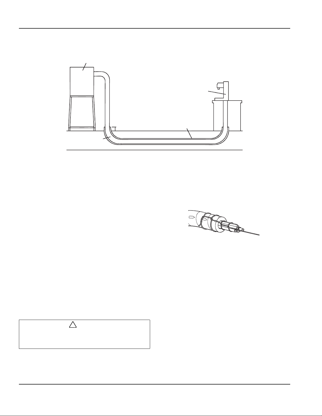
Refrigeration Unit
Dispensing Tower
8” (20.5 cm)
PVC Conduit
6” (15.2 cm)
Wide Sweep Elbows
2 ft (61cm) Radius
Figure 1
!
Caution
Figure 2
Routing Multiplex Conduit
FLOOR CHASES
Before pulling Multiplex conduit through a floor chase,
ensure the floor chase contains the following:
• 8" Minimum PVC Conduit
• Wide Sweep Elbows with a minimum 2 ft (61 cm) radius
• Chase openings should extend 6" (15.2 cm) above floor
• Chase must be clean and dry, no foreign materials
Pulling Conduit Through Floor Chase
1. Determine the most convenient way of routing conduit,
2. Locate steel fish tape and route through chase opening.
3. Locate an appropriate length of rope and tie to end of fish
4. Pull end of fish tape from starting point through chase with
All objects and moisture must be removed from floor
chase before conduit can be routed. It may be necessary
to repeat this process to ensure floor chase is clean.
starting at the end which offers adequate room for
installation. The conduit installation process requires the
assistance of two (2) qualified personnel.
Route fish tape through entire chase until it appears at
opposite end.
tape (end that was routed through chase in step 2).
Approximately 2 ft (61 cm) from steel fish tape/rope
connection, secure a swab to rope (use mop heads or
bundle of rags for swab).
rope and swab. The swab will sweep clean any
construction materials, moisture, or debris that may exist
in floor chase.
Multiplex conduit and uncoil conduit to allow
unrestricted feed during installation process.
6. Locate rope through chase opening and connect to
proper end of Multiplex conduit.
NOTE: Multiplex conduit is designed to be pulled
through a chase in the direction of arrows printed on
conduit (refer to figure 2).
7. After rope has been connected, tape end of co nduit,
including rope, and form conduit end to a point.
Tape will ensure that no contaminants enter conduit
tubes during installation.
8. Place pointed end of Multiplex conduit through
chase opening. While one person pushes the
conduit through chase, another person should be
pulling conduit through chase with rope on opposite
end.
9. Once conduit has been routed through chase, pull
enough conduit through openings to ensure an
adequate supply at each end of chase for
connections.
5. After floor chase has been cleaned, remove steel
fish tape and swab from rope. Locate bundle of
SEALING INSTRUCTIONS
2-2
Part Number EI211017 10/11
Page 9
Section 2 Installation
!
Warning
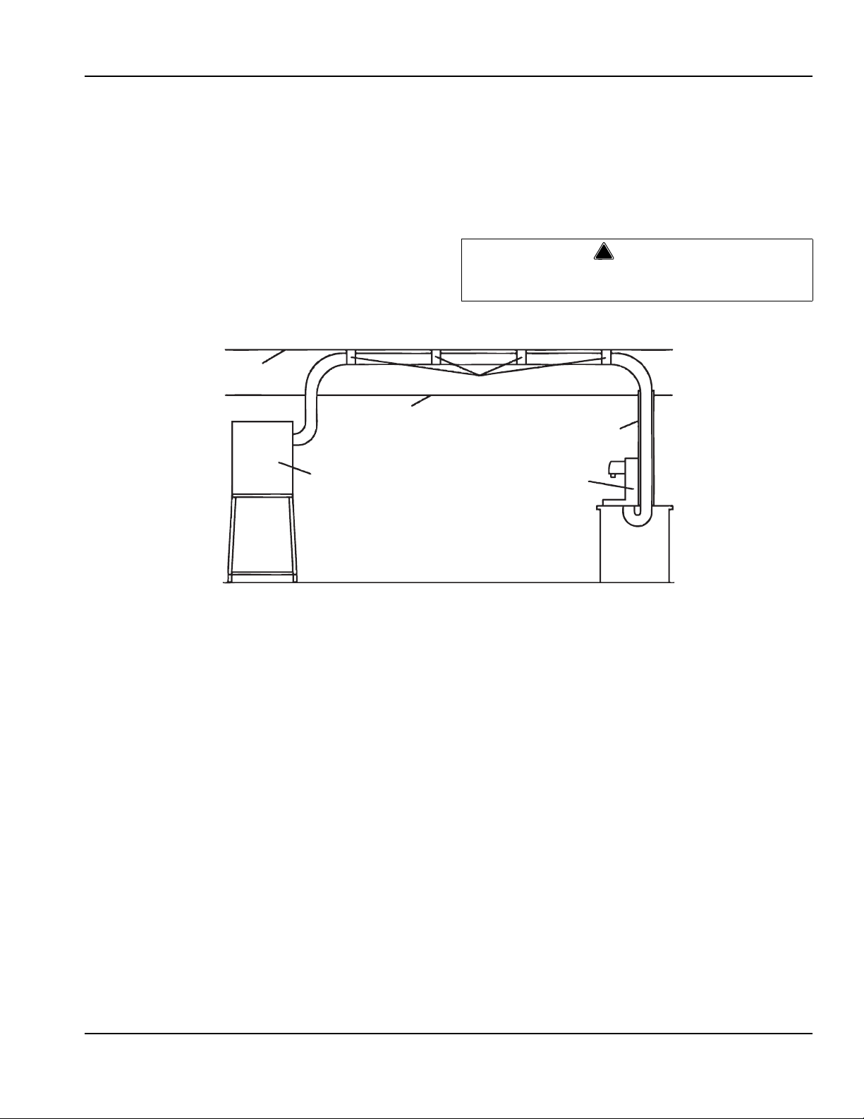
Refrigeration Unit
Dispensing Tower
Ceiling Tiles
Conduit Hangers
Roof
Conduit Shroud
6” (15.2 cm)x 6” (15.2 cm)
Minimum
Figure 3
Aerosol foam is to be used to fill the openings between the
conduit insulation and the inside diameter of the floor
chases. The purpose is to provide an air tight seal at the floor
level to prevent foreign matter from entering the chases.
Please read the manufacturer’s instructions carefully.
1. If the opening is too deep, insert a section of the excess
conduit insulation in the opening prior to using the foam
insulation.
2. Make sure all exposed carbonated water and syrup
lines are well insulated: towers to conduit; conduit
junctions, remote unit to conduit; drive thru junction.
OVERHEAD INSTALLATION
3. Use aluminum foil (if used), and tape, packed in the
inner pack carton to insulate these connections.
4. Cut the conduit sections to fit like a glove over the
exposed lines and fittings.
NOTE: A little extra time spent doing a professional job
initially will eliminate a call back in several days to make
corrections.
Do not inject foam material directly on the connections where
the tubing connects to the barb fittings.
1. Determine the correct location for routing Multiplex
conduit. Be sure to avoid heat ducts, hoods, grills, or any
sharp objects that may exist above drop ceiling tile.
(refer to figure 3)
2. Unspool Multiplex conduit to allow unrestricted feed.
3. Conduit hangers should be spaced no more than 6 ft
centers.
4. Route conduit above ceiling tiles and connect to ceiling
and/or pipes using the appropriate conduit hangers. Be
sure conduit is suspended above ceiling tiles. Concern
should be given when determining appropriate method
of hanging conduit securely. Hangers must not crush or
pinch insulation. This will reduce cooling efficiency.
Once conduit has been routed, ensure an adequate supply
of conduit is provided at each end to make all connections.
Part Number EI211017 10/11 2-3
Page 10
Installation Section 2
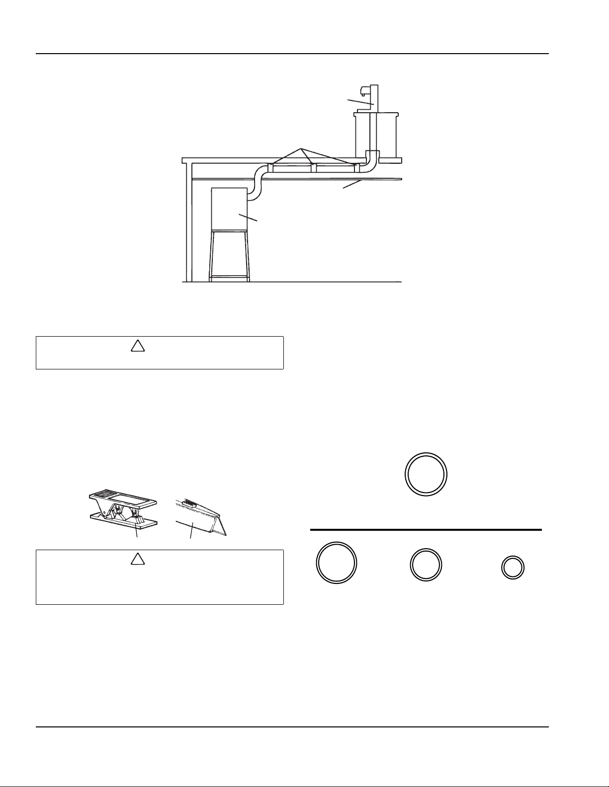
Dispensing Tower
Conduit Hangers
Basement Ceiling
Refrigeration Unit
Figure 4
!
Caution
!
Caution
Razor KnifeButterfly Cutter
Figure 5
Thick Wall Tubing
1/2" x 0.083 W
3/8" x 0.062 W 1/4" x 0.062 W1/2" x 0.062 W
NOTE: Shown actuall size.
Figure 6
BASEMENT CONSTRUCTION
1. Uncoil Multiplex conduit to allow unrestricted feed
during installation process.
2. Route the conduit up basement wall and secure with
appropriate conduit hangers.
Don't crush or pinch conduit insulation with hangers.
3. Conduit hangers should be spaced no more than 6 ft centers
How To Connect The Multiplex Conduit
NOTE: Conduit lines should be long enough to allow
adequate work space when servicing equipment.
All Multiplex conduit syrup lines, carbonated water lines,
and the plain water line are coded for quick identification
and easy installation.
Only an approved cutting tool should be used to cut
polyethylene tubing. Use a new blade so that the tubing will
not be crushed when cutting.
1. Locate the lines of Multiplex conduit routed at
refrigeration unit and dispensing tower.
2. Using an approved razor knife, cut Multiplex conduit
insulation by slicing along top side while peeling
insulation back at the same time.
3. For soda systems, connect each syrup line, carbonated
water line, and plain water line to the appropriate stainless
4. Route conduit above ceiling tiles and connect to
ceiling and/or pipes using the appropriate conduit
hangers. Be sure conduit is suspended above
ceiling tiles. Concern should be given when
determining appropriate method of hanging conduit
securely. Hangers must not crush or pinch
insulation. This will reduce cooling efficiency.
Once conduit has been routed, ensure an adequate
supply of conduit is on hand to make all connections.
steel coil in refrigeration unit. For Glycol systems,
connect to bulkhead fittings.
NOTE: Stainless steel cooling coils in our refrigeration units
may contain either barb fittings or John Guest fittings,
depending on model. Before connecting conduit, identify
whether the conduit is thick wall or thin wall tubing (see
illustration). Thick wall tubing should only be used with barb
stem fittings. John Guest fittings can only be used with thin
wall tubing
2-4
Part Number EI211017 10/11
Page 11
Section 2 Installation
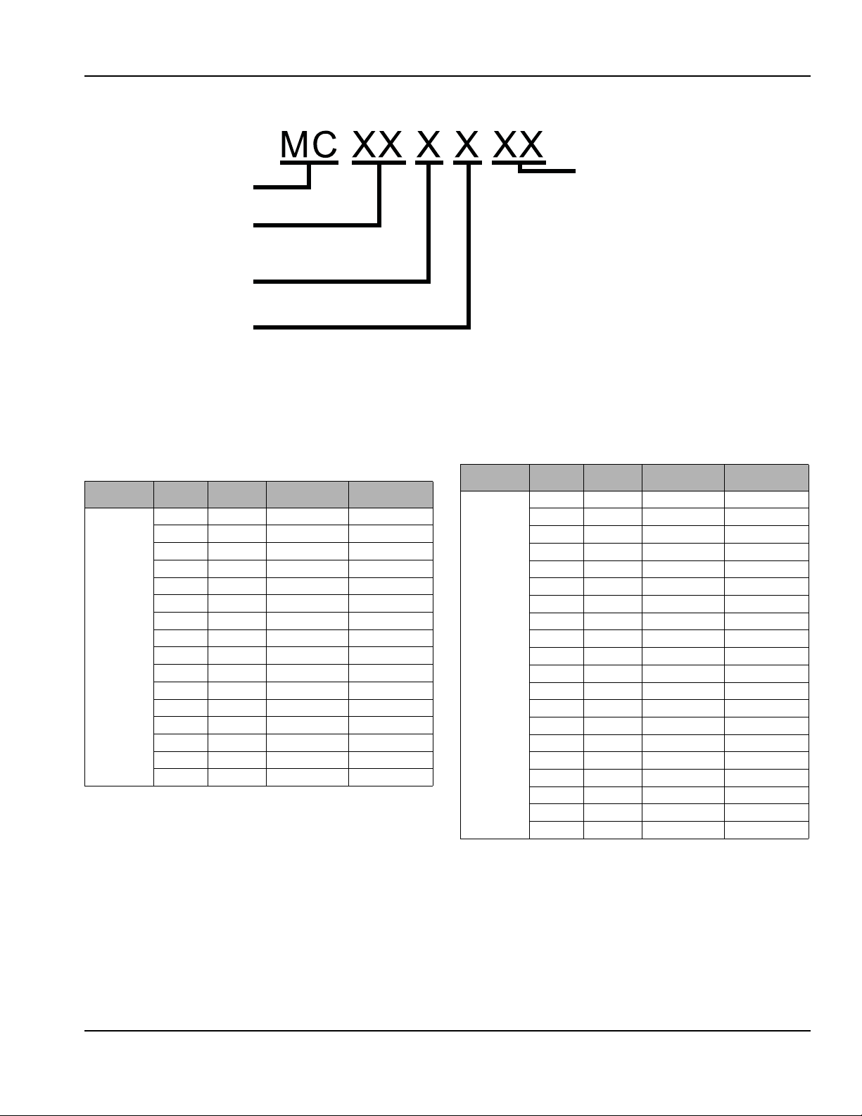
Insulation
X6 = Barrier/Flushable
OX = 3/4" Insulation
1X = 1" Insulation
2X = Special 1" Insulation
3X = w/C02 Wire
4X = Beer Conduit w/Foil Wrap 1" Insulation
5X = Dual Recirculating Circuits
or Special - 2" Insulation
6X = Cabled Chasis
8X = Double Insulation
9X = Uninsulated
Multiplex Conduit
Line Quantity
05 = 5 lines
16 = 16 lines
Water/Glycol 1.0. Line Size
3 = 3/8"
5 = 1/2"
Syrup/Beer 1.0. Line Size
2 = 1/4"
3 = 3/8"
5 = 1/2"
Figure 7
CONDUIT IDENTIFICATION CHART
When suspending Multiplex conduit with conduit hangers, the maximum allowable distance b etween hangers is 6 ft (1.82 m) .
If ambient temperature of the conduit location is 90ºF (32.2ºC) or above, double insulated conduit must be utilized.
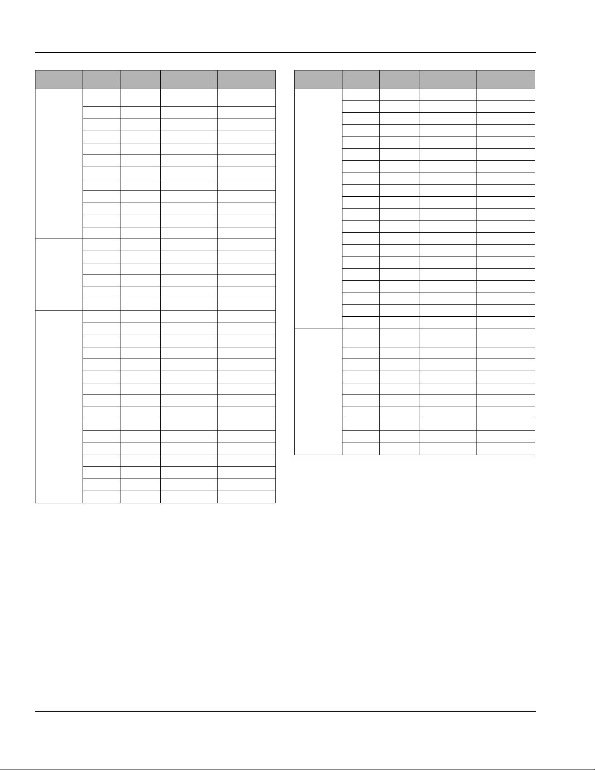
COLOR AND NUMBER CODING
I.D. Size of
Tube / Hose
1/4” Tube
Number Color Suggested Use Tab Clamp Size
S1 White Syrup 10.5
S2 Black
S3 Orange
S4 Red
S5 Blue
S6 Green
S7 Purple
S8 Brown
S9 Pink
S10 Yellow
S11 White
S12 Black
S13 Orange
S14 Red
S15 Blue
S16 Green
I.D. Size of
Tube / Hose
3/8” Tube
Number Color Suggested Use Tab Clamp Size
AF Red Water / Glycol 13.8
AR Red
BF Blue
BR Blue
S1 White Syrup / Beer 13.8
S2 Black
S3 Orange
S4 Red
S5 Blue
S6 Green
S7 Purple
S8 Brown
S9 Pink
S10 Yellow
S11 White
S12 Black
S13 Orange
S14 Red
S15 Blue
S16 Green
Part Number EI211017 10/11 2-5
Page 12
Installation Section 2
I.D. Size of
Tube / Hose
1/2” Tube
1/2” Hose
1/4” Tube
Number Color Suggested Use Tab Clamp Size
VS1 Orange
VS2 Natural
VS3 Green
VS4 White
VS5 Black
VS6 Red
VS7 Blue
VS8 Purple
VS9 Brown
VS10 Pink
VS11 Yellow
VS12 Purple
AF Blue Water / Glycol 18.5
AR Blue
BF Yellow
BR Yellow
WF Black
WR Black
S1 White Syrup 10.5
S2 Black
S3 Orange
S4 Red
S5 Blue
S6 Green
S7 Purple
S8 Brown
S9 Pink
S10 Yellow
S11 White
S12 Black
S13 Orange
S14 Red
S15 Blue
S16 Green
High Viscous
Syrup
17
I.D. Size of
Tube / Hose
3/8” Tube
1/2” Tube
Number Color Suggested Use Tab Clamp Size
AF Red Water / Glycol 13.8
AR Red
BF Blue
BR Blue
S1 White Syrup / Beer 13.8
S2 Black
S3 Orange
S4 Red
S5 Blue
S6 Green
S7 Purple
S8 Brown
S9 Pink
S10 Yellow
S11 White
S12 Black
S13 Orange
S14 Red
S15 Blue
S16 Green
VS1 Orange
VS2 Natural
VS3 Green
VS4 White
VS5 Black
VS6 Red
VS7 Blue
VS8 Purple
VS9 Brown
VS10 Pink
High Viscous
Syrup
17
Product suggestions for conduit tubing
Current conduit tubing is PTE lined. Therefore it is no
longer necessary to make sure pungent flavors are used
with specific tubing. Keeping with that process, when
connecting conduit to syrup boxes and valves, the best
flavor/tubing selection would be to utilize line number S1
for valve number 1, S2 for valve number 2, etc.
2-6
Part Number EI211017 10/11
Page 13

Section 2 Installation
Figure 7
Figure 8
1. Before inserting appropriate conduit lines to John
Guest fittings, ensure that the end of each line is
cut square at a 90° angle.
Figure 10
Figure 11
Figure 12
FITTINGS
Barb Stem Fittings
1. Moisten barbed fittings with warm water .
2. Connect appropriate lines to barbed fittings and secure
with two (2) tab clamps. Tab clamps should be
staggered when connecting (refer to figure 7).
3. Once the end of each line has been cut, lubricate with
water and insert line into John Guest Fitting. Be sure the
tubing is inserted firmly through O-ring in John Guest
fitting.
4. Connect each syrup line, carbonated water line, and
plain water line to the appropriate connection in
dispensing tower. Secure with two (2) tab clamps. If
tower has barbs, a John Guest adapter stem should be
used when connecting to a conduit with John
TEEING INTO MUL TIPLEX CONDUIT SODA SYSTEMS
John Guest Fittings
NOTE: Connections in dispensing towers may contain
either barb stem fittings or John Guest fittings. See
previous section for proper instruction.
1. Locate the section in main conduit where tee
connections are to be made. Measure a 12" (30.5
cm) area in the designated section.
2. Using a razor knife, cut a “X” pattern in designated
section as shown in figure 8. Peel back the ends of foam
insulation and identify each syrup line and water line
located in conduit. Be careful not to cut lines inside
conduit. Even a small “nick” will result in leaks.
3. Using a tubing cutter, cut each syrup line (one [1]
line at a time) in main conduit. Locate barbed tees in
conduit tee kit, connect to each syrup and water line.
Secure with two tab clamps (refer to figure 11).
4. Locate the section of tee conduit. Using a razor
knife, slice foam insulation in a straight line on top
side of conduit. Pull back foam insulation and locate
each syrup line (refer to figure 12).
5. Connect each syrup line in a tee conduit to the
appropriate barbed tee connected to the syrup lines
in the main conduit. Secure with two (2) tab clamps
(refer to figure 11). Be sure to tee line markings
corresponding to the main conduit markings.
Part Number EI211017 10/11 2-7
Page 14

Installation Section 2
Figure 13
Figure 14
6. Locate carbonated water lines in main conduit and
cut using tubing cutter. Locate barbed “Ell” fitting
provided in kit and connect to carbonated water
lines (refer to figure 13).
7. Connect the carbonated water lines in tee conduit to
the appropriate barbed ells connected to carb onated
water lines in main conduit. Secure with two tab
clamps (refer to figure 14).
NOTE: The number of carbonated water lines will vary
depending on the model of the refrigeration unit.
8. Pull the sliced sections of foam insulation back over
openings where connections were made. Using
cloth tape, tape over openings and seal air tight.
9. After ensuring there are no leaks at co nduit
connections, wrap foam insulation tape around the
sliced sections and insulate the Multiplex conduit
completely. This is very important to prevent
condensation and loss efficiency.
10. Seal each chase opening by spraying foam
insulation into each end of chase opening. This will
reduce risk of contamination of conduit in chase.
2-8
Part Number EI211017 10/11
Page 15

Section 2 Installation
Single Circulation Pump - One Circuit
REFRIGERATION UNIT
CIRC.
PUMP
HEAT EXCHANGER
BLUE
TOWER 1
TOWER 2
BLUE
CONDUIT CONDUIT TEE
CARB
TANK
Figure 15
Two Circulation Pump - Two Circuit
REFRIGERATION UNIT
CIRC.
PUMP
HEAT EXCHANGER
CARB
TANK
CIRC.
PUMP
HEAT EXCHANGER
CARB
TANK
CONDUIT CONDUIT TEE
TOWER 1
TOWER 2
BLUE
BLUE
YELLOW
YELLOW
SODA CONDUIT KIT DIAGRAMS
Single Circulation Pump - Two Circuit
REFRIGERATION UNIT
CIRC.
PUMP
CARB
TANK
HEAT EXCHANGER
TOWER 1
BLUE
YELLOW
YELLOW
BLUE
CONDUIT CONDUIT TEE
TOWER 2
Part Number EI211017 10/11 2-9
Page 16

Installation Section 2
Beermaster
Refrigeration Unit
Dispensing
Station
Beer Conduit
6” PVC
Conduit Chase
Wide Sweep Elbows
2 ft Radius
Walk-In Cooler
Figure 1
Figure 2
Beermaster Beer Conduit
INTRODUCTION
The following instructions will provide information for installing Multiplex/Multiplex Beer Conduit with your Beermaster System.
Areas which will be covered include routing the conduit for different bar set-ups, connecting the conduit at the Beermaster
Glycol Chiller, connecting the conduit at the beer cooler , and connecting the conduit at the dispensing stations.
FLOOR CHASES
Before pulling beer conduit through a floor chase, ensure the floor chase contains the following (see Figure 1)
• 6" (minimum) PVC conduit chase
• Wide sweep elbows (2 ft radius)
• Chase openings should extend 6" above floor
• Chase must be clean and dry–no foreign materials
Pulling conduit through floor chase
1. Determine the most convenient way of routing conduit,
starting at the end which offers ade quate room for
installation. The conduit installation process requires the
assistance of at least two (2) qualified personnel.
2. Route the steel fish tape through chase opening. Push
fish tape through entire chase until it appears at
opposite end.
3. Locate an appropriate length of rope and tie to end of
fish tape (end which was routed through chase in step
2). Approximately 2 ft from steel fish tape/rope
connection, secure a swab to rope (use mop heads or a
bundle of rags for swab).
4. Pull end of fish tape from starting point through chase
with rope and swab. The swab will clean any
construction materials, moisture, or debris that may exist
in floor chase. Continue to swab the chase until the
5. After floor chase has been cleaned, remove steel fish
swab exits the chase clean and dry.
tape and swab from rope. Locate bundle of beer conduit
and unspool conduit to allow unrestricted feed during
installation process.
6. Locate rope through floor chase opening and connect to
proper end of beer conduit.
NOTE: The beer conduit is designed to be pulled through
floor chase in the direction of arrows printed on conduit.
7. After rope has been connected, tape end of conduit,
including rope, and form conduit end to a point (see
Figure 2). Tape will ensure that no contaminants enter
conduit tubes during installation.
8. Place pointed end of the conduit through chase
opening. While one person pushes the conduit through
chase, another person should be pulling the conduit
through the chase with rope at the opposite end.
9. Once the conduit has been routed through the chase,
pull enough conduit through the openings to ensure an
adequate supply at each end of the chas e for
connections.
2-10
Part Number EI211017 10/11
Page 17

Section 2 Installation
Figure 3
Beermaster
Refrigeration Unit
Dispensing
Station
Beer Conduit
Conduit Hanger
Walk-In Cooler
Figure 4
OVERHEAD INSTALLATION
Conduit Hanger
Beer Conduit
Beermaster
Refrigeration Unit
Walk-In Cooler
Dispensing
Station
Ceiling Tiles
Refer to Figure 3 for the following:
1. Determine the correct location for routing the beer
conduit. Be sure to avoid heat ducts, hoods, grills, or
any sharp objects that may exist above drop ceiling
tile.
2. Unspool the beer conduit to allow unrestricted feed.
3. Route the conduit above ceiling tiles and connect to
ceiling and/or pipes using the appropriate conduit
BASEMENT CONSTRUCTION
hangers. Be sure the conduit is suspended above
ceiling tiles, not lying on the tiles. Care should be
taken when determining appropriate method of
handing conduit securely. Hangers must not crush
or pinch insulation. This will reduce cooling
efficiency.
4. Once the conduit has been routed, ensure an
adequate supply of conduit is provided at each end
to make all connections.
Refer to Figure 4 for the following:
1. Unspool the beer conduit to allow unrestricted feed
during installation process.
2. Route the conduit up basement wall and secure with
appropriate conduit hangers.
3. After routing the conduit up the basement wall, route
conduit overhead on the basement ceiling. Connect
to the basement ceiling using appropriate conduit
hangers.
4. Once the conduit has been routed, ensure an
adequate supply of conduit is on hand to make all
connections.
Part Number EI211017 10/11 2-11
Page 18

Installation Section 2
Beermaster
Refrigeration Unit
Dispensing
Station
Beer Conduit to
Walk-in Cooler
Main Beer Conduit
Walk-In Cooler
Figure 5
!
Caution
Razor KnifeButterfly Cutter
Figure 6
Connecting Beer Conduit
Before connecting the beer conduit at the walk-in beer
cooler and beer towers, ensure an adequate length of
conduit is being supplied to make proper connections.
Only an approved cutting tool should be used to cut
polyethylene tubing. The cutting tool should contain a
razor sharp cutting blade so that the tubing will not be
crushed when cutting. A razor blade knife or butterfly
tubing cutter is sufficient (see Figure 6). Multiplex packs a
butterfly cutter with each Beermaster Glycol Chiller.
1. Locate the lines of the beer conduit routed to the
Beermaster Glycol Chiller.
2. Using an approved cutting tool, cut the beer conduit
insulation along the top side while peeling i nsulation
back at the same time.
NOTE: Glycol circuit is a pair of lines; one blue and one
red. The blue line is the discharge or su pply line. The red
line is the return line.
3. Locate the return glycol supply lines of the beer conduit
and connect to the corresponding John Guest fitting on
the Beermaster Glycol Chiller.
4. Locate the discharge glycol supply lines of the beer
conduit and connect to the corresponding John Guest
fitting on the Beermaster Glycol Chiller.
5. Locate the glycol lines in the main conduit. Connect the
glycol lines of the beer unit to walk-in cooler conduit to
the glycol lines of the main beer conduit.
6. Locate the beer and glycol supply lines at the
dispensing station. Connect each beer line, incoming
glycol line, and outgoing glycol line to the appropriate
John Guest fitting at the dispensing station.
2-12
Part Number EI211017 10/11
Page 19

Section 2 Installation
Beermaster Conduit Kit
GENERAL
The following instructions will cover installation procedures required for properly connecting each component of the Beermaster
system. These instructions also contain the necessary information required for; calculating restrictor line length, required regulator
operating pressures and start up procedures. It is recommended that before proceeding with these instructions you ensure that
each of the following items have been properly installed. Items listed in suggested order of installation:
1. Glycol Chiller Unit
2. Dispensing Towers
3. Secondary Regulator Kits
4. Beer Conduit
Once the above items have been installed the following instructions can be completed.
NOTE: Your system may not include each item.
Kit contents
Four (4) and Seven (7) line conduit kits
5. High Pressure CO
2 Regulator Kit
6. Blender Kit or Beer Pumps
7. Air Compressor Kit, (optional)
8. Low CO
2 Alarm Kit.
10 and 14 line conduit kits
• Three (3) Return bends
• Eight (8) Elbows
•29 Unions
• Five (5) Tail pieces
• Five (5) Beer nuts
• One (1) 60 ft of PVC tape
• One (1) 60 ft of foil
• One (1) Spanner wrench
• Four (4) Return bends
• 15 Elbows
• 42 Unions
• Eight (8) Tail pieces
• Eight (8) Beer nuts
• One (1) 60 ft of PVC tape
• One (1) 60 ft of foil
• One (1) Spanner wrench
Part Number EI211017 10/11 2-13
Page 20

Installation Section 2
Figure 7
Figure 8
Figure 9
BEERMASTER CONDUIT KIT DIAGRAMS
Single Conduit, Two Beer System
Model 150 Refrigeration Unit
To Beer Keg
Walk-in Cooler
Single Conduit, Eight Beer System
Four Faucet Beer Tower
MC103310 (4 beer & glycol lines)
Model 300 Refrigeration Unit
Single Faucet
Beer Tower
MC043341
(4 line beer conduit [2 beer, 2 glycol lines])
To Beer Keg
Walk-in Cooler
(Shown with optional pump)
Dual Conduit, Eight Beer System
Model 300 Refrigeration Unit
To Beer Keg
Walk-in Cooler
(Shown with optional pump)
To Beer Keg
Walk-in Cooler
MC073341 (2 beer, 2 glycol lines)
MC073341 (2 beer, 2 glycol lines)
MC103310
(8 beer & 6 glycol lines)
Two Faucet
Beer Tower
Two Faucet
Beer Tower
2-14
Part Number EI211017 10/11
Page 21

Section 2 Installation
John Guest
Bulkhead Fitting
Glycol Lines
Figure 10
Figure 11
INSTALLING THE CONDUIT KIT
Connections preview
Review Figures 6, 7 and 8 to determine which best illustrates your particular inst allation. Co nsider the following while
examining the drawings;
Beer conduits have been designed to achieve the proper cooling of each encased beer line. In order to function
properly, you must follow these guidelines:
Up to eight (8) line conduit:
Ten (10) and over line conduit:
• Six (6) beer maximum, One (1) glycol circuit (Two [2]
• Two (2) glycol circuits (Four [4] lines)
lines)
To insure colder dispensing temperatures, glycol should flow directly to the dispensing towers before returning to the
remote Glycol Chiller Unit. After examining the drawings determine the desired glycol circuit to be achieved and
illustrate on paper for referral. Do the same for the assignment of the beer supply lines.
CONNECTIONS
Connecting the glycol chiller to the walk-in cooler or
main beer conduit
1. Route the glycol conduit(s) from the Beermaster
Glycol Chiller to the point of connection on the main
beverage conduit(s). This connection could be done
in the walk-in cooler or at any desired location along
the length of the main beer conduits.
2. Identify the proper glycol lines within the glycol
conduit(s) at the Beermaster Glycol Chiller, cut to
length and insert into the appropriate John Guest
bulkhead fitting(s) found on the side panel of the
Beermaster Glycol Chiller (see Figure 10).
Connecting main beer conduit at walk-in cooler
1. At the top of each beer wall bracket fitting, found on
the dual secondary regulator, secure a Beer Nut,
John Guest adapting tail piece, washer, and 1/2"
John Guest union (see Figure 11).
2. Identify the appropriate beer lines to be connected
to each of the wall bracket fittings, cut to length and
insert into the proper John Guest 1/2" connector
(see Figure 11).
John Guest
Adaptor Tail
Piece
Washer
Wall
Bracket
Fitting
Beer Line to
Tower
1
/2" John
Guest Union
Beer Nut
To Beer Keg
Connecting beer conduit to the tower
3. At the walk-in end of the conduit(s), peel back the
insulation from the beer conduit and identify the
appropriate glycol circuit and lines to be connected
(blue and red). Cut glycol lines and secure to the
appropriate elbow or union connections that are best
suited for connection with the beer conduit.
Glycol lines in
1. Peel the insulation back from the end of the beer
conduit to expose all lines. Locate the appropriate
glycol circuit lines, cut to length and attach a 1/2"
John Guest union to each line (see Figure 12).
2. Attach the opposite end of each 1/2" John Guest
unions to the 1/2" adaptors located at the base of
Part Number EI211017 10/11 2-15
the dispensing tower (see Figure 12).
Page 22

Installation Section 2
Glycol
Manifold
Adjustable
Clamp
Adaptor
1
/2" John
Guest Union
1
/2" John
Guest Union
Glycol
Line
Beer
Line
Beer Conduit
See
"Calculating
Restriction"
for Length
Restrictor
Lines
3
/16" Barb
x 1/2"
John
Guest
Adaptor
Dispensing Tower Dispensing Tower
Dispensing Tower
!
Caution
1/2” John
Guest Union
Branch Beer
Conduit
1/2” John
Guest Elbow
Main Beer Conduit
Figure 13
Figure 12
NOTE: If conduit contains more than one glycol circuit it will be necessary to attach U-bends for each of the additional circuits.
Use a 1/2" U-bend quick connect fitting or the U-bend can be built b y attaching two (2) 1/2" John Guest elbows to one anothe r
by means of a 2" length of 1/2" tubing.
BEER RESTRICTOR LINES
1. Cut each restrictor line to the calculated length and
carefully insert the 3/16" Barb x 1/2" John Guest adaptor
and clamp securely with the adjustable cla mps provided
(see Figure 12).
2. Identify the beer line to be connected to each of the
appropriate restrictor line, cut the beer lines to length
Connecting main beer conduit to branch beer conduit
1. .At the required point of connection carefully split open
and fold back the insulation on the main beer conduit
and identify the correct set of glycol lines (circuit) to
connect to the branch beer conduit. Cut the glycol line(s)
and attach the appropriate 1/2" elbow or union
connections that are best suited to connecting with the
main beer conduit (see Figure 13).
2. Peel the insulation back from the end of the branch beer
conduit to expose all lines. Locate the glycol circuit lines,
cut to length and insert each line into the open end of
the previously attached 1/2" connectors at the m ain beer
conduit (see Figure 13).
3. Locate the appropriate beer line(s) in the main beer
conduit to be connected to the branch conduit. Cut
desired beer line(s) long so that they can be pulled back
and then routed in a smooth curve into the branch
conduit. Attach appropriate beer line(s) from main beer
conduit to beer line(s) in branch beer conduit with 1/2"
John Guest Union(s).
2-16
and attach a 1/2" John Guest Union to each. Neatly
wrap the excess restrictor line securely around the
glycol supply lines to ensure good heat exchange.
Connect the adaptor from each restrictor to the 1/2 "
connector of each of the appropriate beer lines.
To avoid agitation use only straight unio ns when splicing
beer lines.
Part Number EI211017 10/11
Page 23

Section 3
Operation
Once installation is complete, the beverage conduit is ready for op era ti on. Plea se consu lt yo ur eq uipm ent in stallation
guide for instructions on running product. See the maintenan ce section in this manual for information on cleaning and
sanitation.
Part Number EI211017 10/11 3-1
Page 24

Operation Section 3
THIS PA GE INTENTIO NALLY LEFT BLANK
3-2
Part Number EI211017 10/11
Page 25

Section 4
Maintenance
Maintenance Schedule
This section provides a list of periodic maintenance t asks and the scheduled frequency re quired to ensure the proper
operation of your Multiplex dispensing equipment. To ensure quality beverages, prevent down time, and reduce cost s, these
tasks must be performed as indicated.
PERIODIC MAINTENANCE LISTED BY MAJOR COMPONENTS
Dispensing stations
Daily (365 times per year)
• T ake temperature of finished drinks. Pour off the first and
take the temperature of the second drink. The prope r
temperature of drinks must be 40°F (4°C) or less.
Beverage conduits
Every 4 months (3 times per year)
• Inspect beverage conduits for damage. Re-insulate an d
seal any un-insulated areas.
• Remove nozzles and diffusers from each dispensing
valve. Clean with soap and warm water (not hot). Rinse
with carbonated water and reinstall.
• Flush all dispenser drains. Pour hot water down drains at
closing.
• Inspect floor chases and seal any open chase ends.
Air compressor
Monthly (12 times per year)
• Drain condensate water from air compressor tank.
Every 4 months (3 times per year)
• Inspect air compressor filter and replace if clogged. Air
filter must be replaced every 6 months.
Refrigeration unit
Every 4 months (3 times per year)
• • Clean the refrigeration unit air-cooled condenser using
a vacuum cleaner. If equipped with water-cooled
condenser, verify the water discharge temperature is at
105°F (41°C). Adjust water modulating valve if
necessary .
• Inspect water bath to verify water level is at the top of
stand pipe. If below , add water and repair water makeup
device. If excessive amount of water is flowing over
stand pipe, locate leak within bath and repair.
Water filters
• Inspect air compressor to verify cut-in at 70 psi (4.8 bar)
and cut-out at 90 psi (6.3 bar). Adjust pressure switch if
necessary.
• Inspect system for air leaks and repair as required.
• Inspect ice bank within the water bath to verify proper
size ice bank and clarity. Look for uniform, 2" to 4" thick
ice bank.
• Drain, clean, and refill water bath.
• Inspect agitator motor and ensure proper opera tion.
• Inspect the circulating motor/pump assembly. Clean
strainer and oil motor .
• Inspect the carbonating motor/pump assembly. Clean
strainer and oil motor .
• Inspect entire system for leaks and repair as required.
Every 4 months (3 times per year)
• Verify that incoming water pressure is not less than 40
psi (2.8 bar) or greater than 60 psi (4.1 bar) . If equipped
with a water regulator , verify proper setting of 55 ps i (3.8
bar). Adjust if necessary.
Part Number EI211017 10/11 4-1
• If pressure is low, inspect water filter cartridges to ensure
they are able to supply adequate water pressure under
normal system flow . Replace if unable to pro vide
minimum 20 psi (1.4 bar) under load.
Page 26

Maintenance Section 4
Syrup supply
Daily (365 times per year)
Every 4 months (3 times per year)
• Clean general area of syrup hookup with soap and warm
water. Rinse of f all soap.
CO
2 gas supply
Every 4 months (3 times per year)
• Inspect pressure setting at CO
2 high pressure regulator.
Verify proper 90 p si (6.3 bar) pressure setting. Adjust if
necessary .
PERIODIC MAINTENANCE LISTED BY SCHEDULED FREQUENCY
Daily (365 times per year)
• T ake temperature of finished drinks. Pou r off the first and
take the temperature of the second drink. The proper
temperature of drinks must be 40°F (4°C) or less.
• Remove nozzles and diffusers from each dispensing
valve. Clean with soap and warm water (not hot). Rinse
with carbonated water and reinstall.
Every 4 months (3 times per year)
• Using Brix cup and syrup separator, check for proper
carbonated water flows (standard flow: 5 oz. in 4 seconds,
fast flow: 10 oz. in 4 seconds) and syrup to water ratios at
each dispensing station. Adjust as required.
• Inspect beverage conduits for damage. Re-insulate and
seal any un-insulated areas.
• Inspect floor chases and seal any open chase ends.
• Inspect air compressor filter and replace if clogged. Air
filter must be replaced every 6 months.
• Inspect air compressor to verify cut-in at 70 psi (4.8 bar)
and cut-out at 90 psi (6.3 bar). Adjust pressure switch if
necessary .
• Inspect system for air leaks and repair as required.
• Clean the refrigeration unit air-cooled condenser using a
vacuum cleaner. If equipped with water-cooled condenser ,
verify the water discharge temperature is at 105°F (41°C).
Adjust water modulating valve if necessary .
• Inspect water bath to verify water level is at the top of
stand pipe. If below , add water and repair water makeup
device. If excessive amount of water is flowing over stand
pipe, locate leak within bath and repair.
• Inspect ice bank within the water bath to verify proper size
ice bank and clarity . Look for uniform, 2" to 4" thick ice
bank.
• Drain, clean, and refill water bath.
• Inspect syrup lines for proper flavor identification labels.
Replace labels if necessary .
• Disconnect syrup containers. Clean connector with soap
and warm water . Rinse with plain water and reconnect to
syrup containers.
• Inspect pressure setting at syrup pressure regulators.
Verify prop ter pressure setting. Adjust if necessary.
• Inspect system for CO
2 leaks, repair as required.
• Flush all dispenser drains. Pour hot water down drains at
closing.
• Clean general area of syrup hookup with soap and warm
water. Rinse of f all soap.
• Inspect agitator motor and ensure proper operation.
• Inspect the circulating motor/pump assembly. Clean
strainer and oil motor.
• Inspect the carbonating motor/pump assembly. Clean
strainer and oil motor.
• Inspect entire system for leaks and repair as required.
• Verify that incoming water pressure is not less than 40 psi
(2.8 bar) or greater than 60 psi (4.1 bar). If equipped with a
water regulator, verify pr oper setting of 55 psi (3.8 bar).
Adjust if necessary . If pressure is low , inspect water filter
cartridges to ensure they are able to supply adequate
water pressure under normal system flow . Replace if
unable to provide minimum 20 psi (1.4 bar) under load.
• Inspect syrup lines for proper flavor identification labels.
Replace labels if necessary .
• Disconnect syrup containers. Clean connector with soap
and warm water. Rinse with plain water and reconnect to
syrup containers.
• Inspect pressure setting at CO
2 high pressure regulator .
Verify proper 90 psi (6.3 bar) pressure setting. Adjust if
necessary .
• Inspect pressure setting at syrup pressure regulators.
Verify propter pressure setting. Adjust if necessary.
• Inspect system for CO
2 leaks. Repair as required.
4-2
Part Number EI211017 10/11
Page 27

Section 4 Maintenance
!
Warning
!
Warning
CLEANING & SANITIZING THE DISPENSING VALVES & PRODUCT LINES
Maintenance Schedule
Every day
Dispensing valves Remove nozzles and diffusers and soak in mild detergent cleaning solution. Scrub parts
with small bristle brush taking care to clean small crevices and O-ring grooves. Turn OFF
power to dispensing valves. Scrub exterior surfaces, including bottom splash area and
actuator lever, with cleaning solution. Reassemble diffusers and nozzles. Wipe dry exterior
surfaces before turning ON power.
Drip pan and drain hose Wash with mild detergent. Rinse with clean water.
Quick disconnects Wash with mild detergent. Rinse with potable water.
Weekly
Outside, dispenser cabinet Wash with clean water and mild detergent. Wipe dry.
Every 3 months
Syrup circuits Sanitize each syrup circuit. See “Maintenance”.
Water bath Drain, melt ice and clean using detergent and brush; rinse with potable water. Do not use
water over 140°F (60°C).
Every 6 months
Condenser Vacuum fins or use soft bristle brush (scrub brush).
Air purifier filter (if equipped) Replace.
Cleaning Equipment and Supplies
• Recommended cleaner: Any caustic-base (low sudsing,
non-perfumed, easily rinsed) detergent solution which
provides a minimum 2% sodium hydroxide. The solution
must be prepared in accordance wi t h th e ma nu fa cturer’s
instructions. Solution temperature must be between 90°F
(32°C) and 110°F (43°C). Temperatures in excess of this
can cause internal damage to the dispensing valve
components.
• Recommended sanitizer: Any sanitizer which provides a
minimum of 120 parts per million (120 milligrams per liter)
of available chlorine. Solution temperature must be
between 90°F (32°C) and 110°F (43°C). Temperatures in
Sanitizing
BEVERAGE SYSTEM CLEANING
Flush sanitizing solution from syrup system. Residual
sanitizing solution left in system could create a health hazard.
When using cleaning fluids or chemicals, rubber gloves and
eye protection must be worn.
excess of this can cause internal damage to the dispensing
valve components.
• Two five gallon (figals) syrup tanks and fittings, cleaned
and sanitized (one for cleaner; one for sanitizer)
• Containers for cleaner and sanitizer solutions
• Clean, non-abrasive cloths
• Buckets
• Small Brush
• Extra Nozzles
• Extra Jumpers
Sanitize the beverage system at initial start-up as well as
regularly scheduled cleaning. The drain pan must be in
place under soda valves, to carry away detergent and
sanitizing agents that will be flushed through valves.
Part Number EI211017 10/11 4-3
Page 28

Maintenance Section 4
Bag
side
connector
BAG-IN-BOX SYSTEM SANITATION
The procedure below is for the sanitation of one syrup circuit at a time. Repeat to sanitize additional circuits.
Y ou will need the following items to clean and sanitize the
Bag-in-Box (BIB) beverage system:
• Three (3) clean buckets
• Plastic brush or soft cloth
• Mild detergent
• Unscented bleach (5% Na CL O) or
Commercial sanitizer
• Bag-In-Box bag connector
1. Prepare the following in the buckets:
• Bucket 1 — warm to hot tap water for rinsing.
• Bucket 2 — mild detergent and warm to hot water .
• Bucket 3 — mix a solution of unscented bleach (5%
Na CL O) or commercial sanitizer and warm to hot
water. Mixture sho uld supply 100 PPM available
chlorine (1/4 oz. bleach to 1 gallon water).
2. Disconnect the “syrup-line side” of the BIB connector.
4. Connect syrup connector to BIB connector and immerse
both into Bucket 1. A “bag-side” connector can be
created by cutting the connector from an empty
disposable syrup bag.
5. Draw rinse water through system until clean water is
dispensed. Most beverage valves allow the syrup side to
be manually activated by depressing the syrup pallet.
6. Connect Bucket 2 to system.
7. Draw detergent solution through system until solution
is dispensed.
8. Repeat steps 2-7 until all syrup circuits contain
detergent solution.
9. Allow detergent solution to remain in the system for
5 minutes.
10. Connect Bucket 3 to system.
1 1. Draw sanitizing solution through system until solution is
dispensed.
12. Repeat step 11 until all syrup circuit s contain sanitizer
solution.
13. Allow sanitizer solution to remain in system for 15
minutes.
14. Remove nozzles and diffusers from beverage valves.
15. Scrub nozzles, diffusers and all removable valve parts
(except electrical parts) with a plastic brush or a soft cloth
and the detergent solution.
16. Soak nozzles, diffusers and removable valve parts
(except electrical parts) in sanitizer for 15 minutes.
17. Replace nozzles, diffusers and valve parts.
3. Rinse connector with warm tap water .
4-4
18. Connect Bucket 1 to system Draw rinse water through
system until no presence of sanitizer is detected.
19. Attach syrup connectors to BIBs.
20. Draw syrup through system until only syrup is dispensed.
21. Discard first 2 drinks.
Part Number EI211017 10/11
Page 29

Section 4 Maintenance
!
Caution
FIGAL BEVERAGE SYSTEM
1. Prepare the following in three clean Figal tanks:
• Rinse tank - fill with room temperature tap water.
• Detergent tank - mix approved beverage system
cleaner with warm water as directed.
• Sanitizing tank - mix a solution of unscented
bleach (5% Na CL O) or commercial sanitizer and
warm to hot water. Mixture should supply 100 PPM
available chlorine (1/4 oz. bleach to 1 gallon water).
2. Disconnect all product and water lines from product
tanks and remove carbonator.
3. Locate the Figal syrup tank for the circuit to be
sanitized. Remove both quick disconnects from the
Figal syrup tank. Rinse quick disconnects in tap water.
4. Connect rinse tank to the syrup line. Draw clean rinse
water through the valve until syrup is flushed from the
system.
5. Connect detergent tank to the syrup line and draw
detergent through the valve for two minutes. Then,
allow remaining detergent to stay in the system for
five minutes.
6. Connect rinse tank to the syrup line. Draw clean rinse
water through the valve until detergent is flushed from
the system.
7. Remove valve nozzle and diffuser as shown in Daily
Cleaning instructions. Using a plastic brush or a soft
cloth and warm water, scru b the nozzle, diffuser, bottom
of the dispensing valve and cup lever, if applicable.
8. Place removable valve parts (EXCEPT solenoids) in
sanitizing solution for 15 minutes.
Shipping, Storage and Relocation
Before shipping, storing, or relocating this unit,
syrup systems must be sanitized. After sanitizing,
all liquids (sanitizing solution and water) must be
purged from the unit. A freezing environment
causes residual sanitizing solution or water
remaining inside the unit to freeze, resulting in
damage to internal components.
9. Replace valve diffuser and nozzle on the beverage valve.
10. Connect sanitizer tank to the syrup line and draw sanitizer
through the valve for two minutes. Allow sanitizer to
remain in the system for a minimum of 15 minutes.
1 1. Reconnect syrup and carbonated water lines.
12. Draw syrup through the lines to rinse the system.
Discard drinks until at least two cups of satisfactory
tasting beverage are dispensed through the valve.
Part Number EI211017 10/11 4-5
Page 30

Maintenance Section 4
THIS PA GE INTENTIO NALLY LEFT BLANK
4-6
Part Number EI211017 10/11
Page 31

Checklist
!
Warning
Section 5
Before Calling for Service
If a problem arises during operation of your post mix
soda refrigeration unit, follow the checklist below before
calling service. Routine adjustments and maintenance
procedures are not covered by the warranty.
Only trained and certified electrical and plumbing
technicians must service this unit. All wiring and
plumbing must conform to national and local codes.
SODA SYSTEMS
Problem Possible Cause To Correct
All corresponding valves dispensing no
syrup.
No syrup at only one dispensing valve. Syrup Shut-off V alve closed or partially
Malfunction of syrup system. Refer to Troubleshooting “Section 8: Syrup
System” under No syrup or insufficient syrup
in finished drink.
Remove top cover from Dispensing valve or
closed.
Mounting Block restricted. Remove Dispensing valve from Mounting
T ower. Locate Syrup Shut-off Valve on right
hand side of Dispensing valve. Verify shut-off
is turned fully open.
Block. Place cup over Syrup outlet on
Mounting Block and carefully open Syrup
Shut-off V alve. If little or no syrup is present,
Mounting Block is restricted. Remove and
clean mounting block. Replace if necessary.
NO SYRUP OR INSUFFICIENT SYRUP IN FINISHED DRINK
No carbonated water at half or all dispensing
valves.
Flow Control our of adjustment or inoperative. Readjust Flow Control to proper Brix. If no
response, clean Syrup Flow Control. Replace
if necessary.
Valve Port restricted. Clean Syrup valve Port Assembly.
Seat swollen. Replace Syrup Seat.
Solenoid Coil defective. Replace Syrup Solenoid Coil.
Malfunction of Carbonated Water System. Refer to Troubleshooting “Section 2:
Carbonated Water System” under No
carbonated water at any of the dispensing
valves.
Part Number EI211017 10/11 5-1
Page 32

Before Calling for Service Section 5
Problem Possible Cause To Correct
NO CARBONATED WATER OR INSUFFICIENT CARBONATED WATER IN FINISHED DRINK
No Carbonated Water only at one dispensing
valve.
NO WATER OR INSUFFICIENT WATER IN FINISHED DRINKS
All valves dispensing noncarbonated
drinks no water.
Problem occurs at only one dispensing
valve.
Too much Syrup, Carbonated Water or
Water in finished drink. Problem occurs
at only one dispensing valve.
Too much syrup in finished drink. All
valves dispensing same flavor-too much
syrup.
Too much water in finished drink. All
valves dispensing noncarbonated drink
too much water.
Syrup or Carbonated Water or Water
dripping from Nozzle.
Carbonated water Shut-off Valve closed or
partially closed.
Mounting Block restricted. Place cup over Carbonated Water outlet on
Flow Control our of adjustment or inoperative. Readjust Flow Control to proper Brix (5 oz in
Valve Port restricted. Clean Carbonated Water valve Port
Seat swollen. Replace Carbonated Water Seat.
Solenoid Coil defective. Replace Carbonated Water Solenoid Coil.
Carbonated Water Switch defective (black). Replaced Carbonated Water Switch.
Water Shut-off Valve closed or partially
closed.
Syrup, carbonated water, or noncarbonated
water flow control out of adjustment or
inoperative.
Malfunction of syrup system. Refer to Troubleshooting “Section 8: Syrup
Malfunction of water Booster system. Refer to Troubleshooting “Section 9: W ater
Valve port scarred. Disassemble appropriate Syrup or Water
Armature Spring or Retaining Ring
broken.
Seat scarred or obstructed. Disassemble appropriate Syrup or Water
Remove top cover from Dispensing valve or
T ower. Locate Carbonated Water Shut-off
Valve on left hand side of Dispensing valve.
Verify Shut-off Valve is turned fully open.
Remove Dispensing valve from Mounting
Block.
Mounting Block and carefully open
Carbonated Water Shut-off V alve. If little or no
Carbonated Water is present, Mounting
Block is restricted. Remove and clean
mounting block. Replace if necessary.
4 seconds Standard valve, 10 oz in 4
seconds Fast Flow valve). If no response,
clean Carbonated Water Flow Control.
Replace if necessary.
Assembly.
Refer to Troubleshooting “Section 9: Water
Booster System” under Low or No Water
Pressure at Noncarbonated Beverages.
Refer to this section on No carbonated water
at only one dispensing valve in the
dispensing valve.
Readjust appropriate Flow Control. If Flow
Control does not respond to adjustment,
clean Flow Control. Replace if necessary.
Carbonated Water Flow rates: (5 oz in 4
seconds Standard valve, 10 oz in 4 seconds
Fast Flow valve).
System” under Drinks too sweet.
Booster System” under Qualifier: Pump and
motor cycles “on” and “off” excessively .
Assembly. Examine valve Port for scars or
nicks. Replace if necessary.
Disassemble appropriate Syrup or Water
Assembly. Examine Armature, Spring and
Retainer Ring. If damaged, replace.
Assembly. Examine Seat, if scarred, replace.
If foreign material is found in Assembly,
remove, reassemble.
5-2
Part Number EI211017 10/11
Page 33

Section 5 Before Calling for Service
Problem Possible Cause To Correct
Valves will not activate when Selection
Panel pressed. Problem occurs at two (2)
or three (3) consecutive Valves on one
(1) tower.
Problem occurs at all valves on one (1)
dispensing tower.
Problem occurs at only one (1)
dispensing valve.
Valve will not shut “off”. Mo is t u re o n Po r ti o n Co n t ro l T i m e r o r C on t a c t
Transformer inoperative. Verify wire leads from Transformer have solid
connections. Switch low voltage lead from
Transformer supplying power to left and right
hand side of T ower . If V alves operate and the
other three do not, Transformer is defective.
Replace.
Dispensing tower’s “on” and “off” T oggle
defective.
No power to transformer or transformer
defective.
Dispensing tower’s “on” and “off” is Switch
defective.
Poor connection on valve Wire Harness. Trace wiring on defective valve and
Portion Control Timer inoperative. Replace the problem valve Portion Control
Selection Switch inoperative. Replace defective Portion Control Timer with
Poor connection at Contact Clips on
Selection Panel (with Portion Control Timer).
Clips.
Portion Control Timer Adjustment Screw
turned beyond control limit.
If after switching Leads, the three valves still
do not operate, the “on” and “off” Toggle
Switch is defective.
Verify power with a voltmeter at wall outlet.
Verify power across low voltage leads on
transformer. If 24 volts are present “on” and
“off” Toggle Switch is defective. Replace.
Verify Main Power Supply and power at
Transformer Leads replace “on” and “off”
Switch if operative.
reconnect any loose wires. Clean and
reconnect any corroded connections.
Timer with a known Operative Timer. If valve
then operates, Portion Control Timer was
defective. Replace.
operative Timer . If V alves still will not activate,
Selection Panel is defective. Replace
Selection Switch.
Examine Contact Clips on Selection Panel
and insure proper contact between Portion
Control Timer and Contact Clips.
Remove top cover from Dispensing Tower .
Remove all moisture from Portion Control
Timer and Contacts.
Turn Portion Control Adjustment Screws on
defective valve counterclockwise 10
complete turns. If valve shuts off when
selection is pressed, readjust for proper
portions.
Note: Several revolutions may be necessary
to bring control back into range.
Portion Control Timer defective. Verify above probables are not the problem.
Push “on/off” Switch for Dispensing Tower to
the “off” position. If valve ceases to dispense
when pushed to “on” position, Portion Control
Timer is defective. Replace.
Selection Panel defective. Push “on/off” Switch for dispensing tower to
the “off” position. If valve ceases and then
continues to dispense when switch is pushed
in “on” position, Selection Panel is defective.
Replace.
Part Number EI211017 10/11 5-3
Page 34

Before Calling for Service Section 5
Problem Possible Cause To Correct
Foaming of finished products. Nozzles, Syrup Tube Diffusers dirty. Remove and clean Nozzle Assemblies and
reassemble.
Warm drinks. Refer to Troubleshooting “Section 7:
Refrigeration System” under Warm drinks.
Incorrect pressure on syrup. Verify pressure supplied to sugar base
products is at 60 psi (4.2 kg/cm2). Adjust
Medium Pressure Regulator if necessary.
Verify pressure supplied to diet product is at
15 psi (1.1 kg/cm2). Adjust Low Pressure
Regulator if necessary.
Note: Insure the Low Pressure Supply Line
has not mistakenly been switched for a
Medium Pressure Supply Line on the diet
tank.
Unit totally inoperative; all electrical
switches in the “on” position.
Change-over Valve Medium or Low Pressure
is in the wrong position.
Air or CO
Flake ice. Only cube ice should be used for carbonated
Improper adjustment of valve. Insure carbonated water flow is properly set
Power failure, all power to system is “off”, or
Fuse/Circuit Breaker is “open”.
2 gas in syrup line. Replace empty Syrup Tank. Dispense Syrup
Verify valve Medium to Low Pressure is in the
Low Pressure position for diet products.
from valve until consistent flow is achieved
and product stabilizes. If evidence of air is still
entering line, replace Liquid Disconnect
which is allowing air to be drawn into syrup
supply.
beverages.
(5 oz. in 4 seconds standard valve, 10 oz in
4 seconds Fast Flow valve). Insure Brix is
properly set. Adjust as necessary.
Check Circuit Breaker. Reset. Examine T ime
Delay, replace if necessary.
5-4
Part Number EI211017 10/11
Page 35

Section 5 Before Calling for Service
BEERMASTER SYSTEMS
Problem Possible Cause To Correct
Section 1: Restriction
Too little restriction
Too much or too little restriction in a draught beer system will cause drawing problems. If draught beer system does not have
enough restriction it may cause the following problems:
A recovery problem simply means that
the beer is leaving the beer line faster
When drawing one beer, the beer
flows very fast.
than the keg can fill the line. When this
occurs it creates a vacuum in the keg
which acts as if there was a low pressure
on the beer in the keg. This causes the
to come out of the beer line causing
CO
2
If a pitcher is drawn, the beer starts
clear then starts to show intermittent
streaks of foam followed by all foam.
foaming problems. (The following
symptoms occur most frequently during
the high volume time of day.)
Beer draws too fast. If the beer draws
clear but too fast and the pressure is
properly set, there may not be enough
restriction in the system.
Beer draws clear but foams in the
glass.
The beer draws too fast to satisfy the
retailer and his help.
Too much restriction
If a draught beer system is over restricted it may cause the following problems:
Beer draws too slow Beer draws too slowly with little or no
head.
The beer appears to flutter or swirl
out of the faucet causing the CO
break out of the beer and thus
creating excess foam.
Since the recovery problem symptoms
simulate a low pressure problem, check to
make sure that the CO
pressure in the keg is
2
flowing and set properly.
Refer to your records to recheck your
restriction calculation for the system. If you
find your line does not have enough
restriction, add the extra restriction to the
3/16" end of the beer line. If you have no
records, make up a new beer line with the
proper restriction and replace the existing
line.
Follow the second corrective step above.
If the beer still flows too fast, continue to add
more 3/16" restrictor line to the system to
meet the retailer’s needs.
First, ensure that the keg is properly tapped.
Second, ensure that the CO
is set at the
2
proper pressure and is flowing to the keg.
Check the beer faucet to ensure that there is
no burr by the vent hole on the inside of the
faucet.
Systematically remove 6" of the 3/16"
to
restrictor line until the beer flows with a full
2
faucet and at a rate of flow desired by the
retailer.
Part Number EI211017 10/11 5-5
Page 36

Before Calling for Service Section 5
Problem Possible Cause To Correct
Section 2: Beermaster Glycol Chiller System
When troubleshooting a closed remote system, one should consider the following areas:
Temperature Beer draws warm and is all foam. Check coolant circulation by:
• Inspecting the coolant circulation pump to
ensure it is on and running.
• Inspecting the coolant return line in
reservoir to ensure it is circulating. Replace
pump if necessary.
Check coolant temperature by:
• Adjusting the range from 27°F (-2.7°C) to
29°F (-1.6°C).
• Fill reservoir to proper level with 3:1 glycol
mix.
No beer flows through system. Check tap check ball and free if stuck. Check
Coolant temperature. If it is less than 27°F
(-2.7°C), the beer in the lines may be frozen.
Turn OFF coolant compressor, then adjust
coolant temperature to be between 27°F
(-2.7°C) and 29°F (-1.6°C).
First beer out always seems
foamy or streaky.
Beer in cooler is above 40°F
(4.4°C).
Glycol is dirty or too weak. Clean reservoir and add new glycol solution
Glycol solution is too warm. Check outlet and inspect agitator for proper
Pressure Beer runs with streaks. System may be under restricted. Add
Beer draws great during slow time of
day but turns to all foam during peak
sale periods.
Off-taste Beer is flat. Adjust air blender by increasing CO
Beer has off-taste (bitte r or
“skunky”).
Ensure that coolant line is in direct contact
with the beer line right up to the back of the
shank. If not, place aluminum foil between
beer line and coolant line, then insulate. This
will transfer the cold to the beer line.
Temperature of cooler id eally should be less
than 38°F (3.3°C). Contact an authorized
refrigeration service agency to set cooler.
(add new glycol to weak solution). Should
give Brix on sugar refractor.
operation.
additional restriction to system by adding
additional 3/16" I.D. vinyl tubing to the faucet
end of the system.
See above. Check regulator for proper
operation. Check primary regulator to see if it
allows enough CO
Check walk-in cooler temperature is 38°F
(3.3°C) or less.
and decreasing air in blend. Or there is no
Air/ CO
Change air intake filters. Check for moisture
in air tank. Clean system. Check air intake
supply. Check air filter and trap. Ensure
proper rotation of kegs in series. Check
cleaning schedule for beer lines.
blender.
2
for secondary regulators.
2
in blend
2
5-6
Part Number EI211017 10/11
Page 37

Page 38

© 2011 Manitowoc
Continuing product improvements
may necessitate change of
specifications without notice.
Part Number EI211017 10/11
Manitowoc Beverage Systems
Sellersburg, IN 47172, USA
Ph: 812-246-7000 Fax: 812-246-7024
Visit us online at: www.manitowocfsg.com
2100 Future Drive
 Loading...