

Page 1
Blend-In-Cup (BIC)
BeverageSystem
Installation, Operation and Maintenance Manual
Original Instructions — This manual is updated as new information and models are released. Visit our website for the
latestmanual. www.manitowocbeverage.com/us
Part Number 9291386 6/14
Page 2

Safety Notices
As you work on Multiplex equipment, be sure to pay close
attention to the safety notices in this manual. Disregarding
the notices may lead to serious injury and/or damage to the
equipment.
Throughout this manual, you will see the following types of
safety notices:
Warning
n
Text in a Warning box alerts you to a potential personal
injury situation. Be sure to read the Warning statement
before proceeding, and work carefully.
Caution
,
Text in a Caution box alerts you to a situation in which
you could damage the equipment. Be sure to read
the Caution statement before proceeding, and work
carefully.
Procedural Notices
Read These Before Proceeding:
Caution
,
Proper installation, care and maintenance are essential
for maximum performance and trouble-free operation
of your Multiplex equipment. Read and understand
this manual. It contains valuable care and maintenance
information. If you encounter problems not covered
by this manual, do not proceed, contact Manitowoc
Foodservice. We will be happy to provide assistance.
Important
Routine adjustments and maintenance procedures
outlined in this manual are not covered by the warranty.
Warning
n
PERSONAL INJURY POTENTIAL
Do not operate equipment that has been misused,
abused, neglected, damaged, or altered/modified from
that of original manufactured specifications.
As you work on Multiplex equipment, be sure to read the
procedural notices in this manual. These notices supply
helpful information which may assist you as you work.
Throughout this manual, you will see the following types of
procedural notices:
Important
Text in an Important box provides you with information
that may help you perform a procedure more efficiently.
Disregarding this information will not cause damage or
injury, but it may slow you down as you work.
NOTE: Text set off as a Note provides you with simple, but
useful, extra information about the procedure you are
performing.
NOTE: SAVE THESE INSTRUCTIONS.
We reserve the right to make product improvements at
any time. Specifications and design are subject to change
without notice.
Page 3

Section 1
General Information
Section 2
Installation
Table of Contents
Read This Manual ............................................................................................................... 5
About Blend-In-Cup ...........................................................................................................5
Unit Inspection ................................................................................................................... 5
Model Numbers .................................................................................................................. 5
Serial Number Location ..................................................................................................... 5
Warranty Information ........................................................................................................ 6
Specifications .....................................................................................................................7
Dimensions ...............................................................................................................................................7
Capacity & Weight ..................................................................................................................................7
Product Delivery Location ...................................................................................................................8
Refrigerant Charge .................................................................................................................................8
R-290 Ice Maker .......................................................................................................................................8
R-404A Ice Maker ....................................................................................................................................9
Electrical ................................................................................................................................................. 10
Air / CO2, Plain & Chilled Water Inlets .......................................................................................... 11
System Pressures ................................................................................................................................. 11
Drain Connections .............................................................................................................................. 11
Section 3
Operation
Step-by-Step Installation .................................................................................................13
Pre-installation Checklist .................................................................................................................. 13
Connections .......................................................................................................................................... 14
Installation Checklist .......................................................................................................................... 15
Start-Up & Cleaning ............................................................................................................................ 15
Demonstrate ......................................................................................................................................... 16
Post Installation Checklist ................................................................................................................ 16
Component Identification ...............................................................................................17
Sequence of Operation ....................................................................................................17
Normal Operation ............................................................................................................................... 17
Ice Making .............................................................................................................................................. 18
Touch Screens ................................................................................................................... 19
Drink Selection Screen ...................................................................................................................... 19
Flavor Selection Screen ..................................................................................................................... 20
Size Screen ............................................................................................................................................. 21
Main Menu Screen .............................................................................................................................. 24
Manager’s Menu Screen....................................................................................................................25
Calibration Procedure ........................................................................................................................ 27
Product Inventory Screen .................................................................................................................29
Cleaning Screen ................................................................................................................................... 31
Other Operations .............................................................................................................32
Loading Recipes ................................................................................................................................... 32
Recommended Cups ..........................................................................................................................32
Part Number 9291386 6/14 3
Page 4

Section 4
Maintenance
Section 5
Troubleshooting
Table of Contents (continued)
General Maintenance .......................................................................................................33
Door Gasket Maintenance ............................................................................................................... 33
Drain Maintenance - Inside Lower Cabinet ................................................................................33
Refrigerators .......................................................................................................................................... 34
Stainless Steel Care & Cleaning ...................................................................................................... 34
Doors/Hinges ........................................................................................................................................ 34
Preventing Blower Coil Corrosion ................................................................................................. 34
Daily Cleaning - Zone 1 ....................................................................................................35
Gather the Following Supplies ....................................................................................................... 35
Blenders / Dispense Area Cleaning & Sanitizing ...................................................................... 36
Weekly Cleaning - Zone 2 ................................................................................................40
Gather the Following Supplies ....................................................................................................... 40
Product Line Cleaning & Sanitizing .............................................................................................. 41
Sanitizing Ice Bin & Water Nozzles (Optional) ........................................................................... 43
Blenders / Dispense Area Cleaning & Sanitizing ...................................................................... 45
Drain Cleaning (Optional) ................................................................................................................ 49
Monthly Cleaning - Zone 3 ..............................................................................................51
Gather the Following Supplies ....................................................................................................... 51
Ice Maker Cleaning & Sanitizing ..................................................................................................... 52
Other Monthly Tasks ........................................................................................................................... 55
Biannual Descaling - Zone 3 ............................................................................................56
Turn ON Descaling .............................................................................................................................. 56
Gather the Following Supplies ....................................................................................................... 57
Ice Maker / Bin Descaling, Cleaning & Sanitizing ..................................................................... 58
Turn OFF Descaling .............................................................................................................................62
Ice Machine Cleaning .......................................................................................................63
Tools Required ...................................................................................................................................... 63
Unit Preparation...................................................................................................................................63
Ice Machine Descaling ....................................................................................................................... 63
Ice Machine Sanitizing ....................................................................................................................... 64
Bin / Dispenser Descale, Clean, & Sanitize .................................................................................. 64
Descaling ................................................................................................................................................ 64
Sanitizing ................................................................................................................................................ 64
Full Disassembly Descale, Clean & Sanitize ................................................................................ 65
Product Line Flush ............................................................................................................66
Gather the Following Supplies ....................................................................................................... 66
Annual Planned Maintenance .........................................................................................71
Before Calling For Service Checklist ...............................................................................73
Procedure to Clear Blocked Line .....................................................................................75
How to Check Air/CO2 Pressure .......................................................................................76
How to Check Plain Water Pressure ................................................................................77
Section 6
Tools & Cleaning Supplies
Cleaning Kits ..................................................................................................................... 79
4 Part Number 9291386 6/14
Page 5
Section 1
General Information
Read This Manual
Manitowoc Beverage Systems developed this manual as a
reference guide for the owner/operator and installer of this
equipment. Please read this manual before installation or
operation of the machine. A qualified service technician
must perform installation and start-up of this equipment.
Consult Section 5 within this manual for service assistance.
If you cannot correct the service problem, call your Service
Agent or Distributor. Always have your model and serial
number available when you call.
Your Service Agent _______________________________
Service Agent Telephone Number ____________________
Your Local Distributor______________________________
Distributor Telephone Number ______________________
Model Number __________________________________
Serial Number ___________________________________
Installation Date _________________________________
About Blend-In-Cup
The Blend-In-Cup beverage system is a self-contained
dispensing unit that allows the operator to make flavor
combinations of blended and non-blended drinks. It holds
product flavoring in a refrigerated reach-in base enclosure,
has a refrigerated ice making machine and includes one or
two mixing modules.
The operator controls and accesses the unit using a lighted
touch screen. Icons on the drink selection screens represent
the primary flavor combinations for the drinks. There are
multiple drink size options. Menu changes and additions
are uploaded using a USB mass storage device and the
Menu Connect Software platform.
On-screen instructions also include operator procedures for
cleaning/sanitizing, checking inventory, replacing product
bags, selecting drink sizes and manually preparing drinks.
Managers and technicians have access to menu/software
updates, diagnostics and other service screens.
Warning
n
Do not damage the refrigeration circuit when installing,
maintaining or servicing the unit.
Warning
n
Do not operate equipment that has been misused,
abused, neglected, damaged, or altered/modified from
that of original manufactured specifications.
This appliance is not intended for use by persons
(including children) with reduced physical, sensory
or mental capabilities, or lack of experience and
knowledge, unless they have been given supervision
concerning use of the appliance by a person responsible
for their safety.
Model Numbers
This manual covers the following models:
Blend-In-Cup Beverage Systems
MB-8-1, MB-8-2, MB-8-1A, MB-8-2A, MB-8-1BF, MB-8-1D,
MB-8-2D, MB-8-1E, MB-8-2E, MB-8-1P, MB-8-2P,
MB-8-1PP, MB-8-1U, MB-8-2U
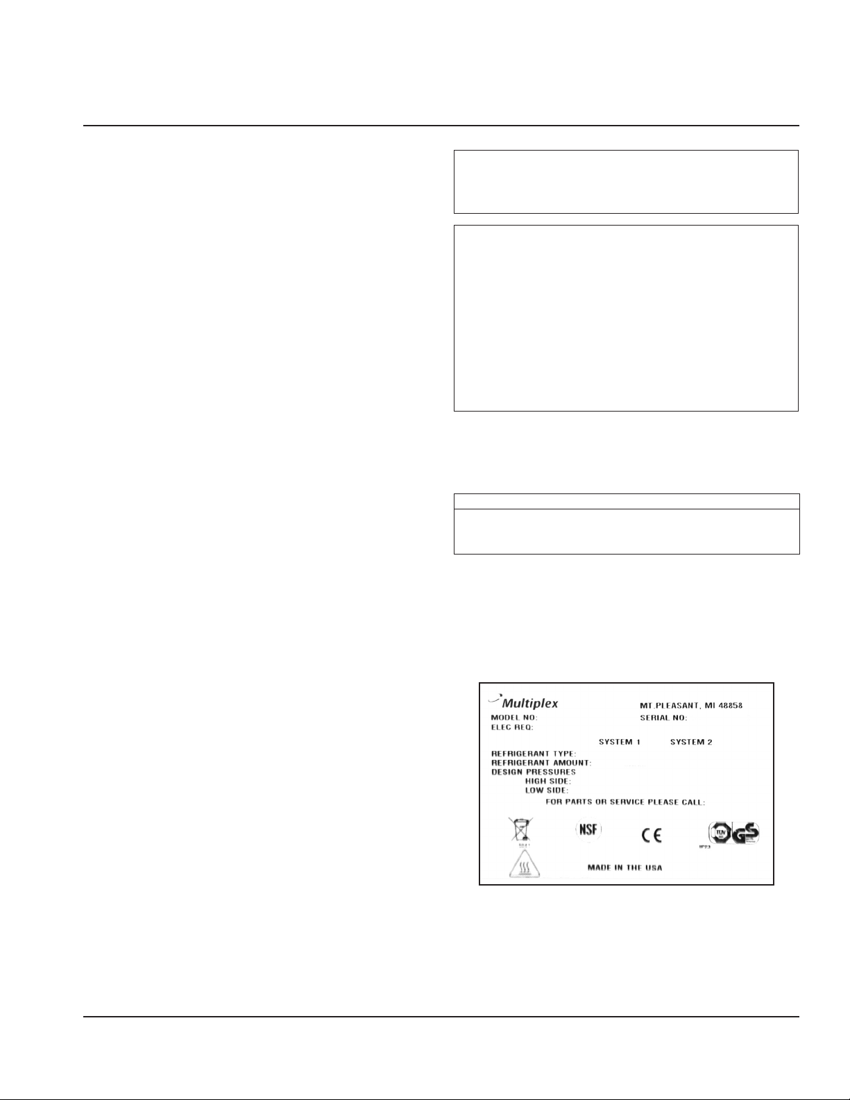
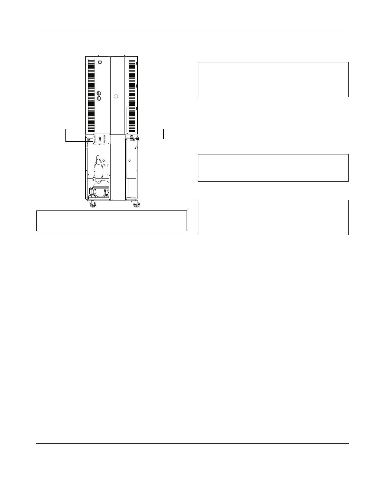
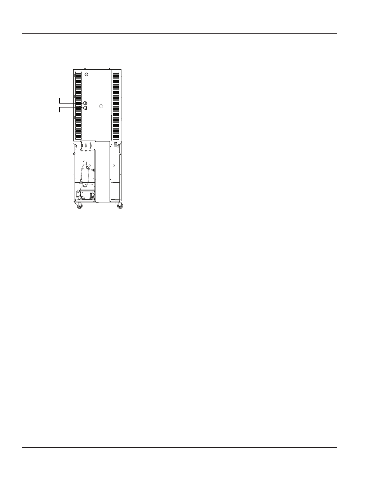
Serial Number Location
The Blend-In-Cup beverage system serial number is listed
on the serial number decal affixed to the middle of the
lower back panel. Another serial number decal is located on
the right side of the machine.
Unit Inspection
Thoroughly inspect the unit upon delivery. Immediately
report any damage that occurred during transportation
to the delivery carrier. Request a written inspection report
from a claims inspector to document any necessary claim.
See “Pre-installation Checklist” on page 13.
Part Number 9291386 6/14 5
Sample Serial Tag
Page 6

General Information Section 1
Warranty Information
Consult your local Service Agent or Representative for terms
and conditions of your warranty. Your warranty specifically
excludes all general adjustments, cleaning, accessories and
related servicing.
Your warranty card must be returned to activate the
warranty on this equipment. If a warranty card is not
returned, the warranty period can begin when the
equipment leaves the Manitowoc Beverage Systems factory.
No equipment may be returned to Manitowoc Beverage
Systems without a written Return Materials Authorization
(RMA). Equipment returned without an RMA will be refused
at Manitowoc Beverage System’s dock and returned to the
sender at the sender’s expense.
Please contact your local distributor for return procedures.
Full explanation of the Limited Warranty for Multiplex
Blended Ice Machines can be found in the warranty
statement at the back of this manual.
6 Part Number 9291386 6/14
Page 7
Section 1 General Information
Specifications
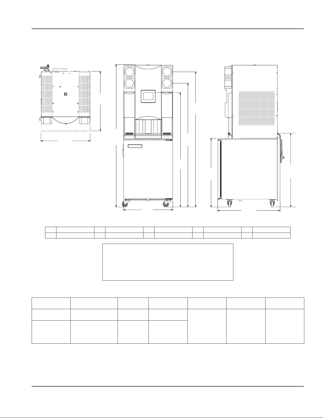
DIMENSIONS
B
C
A
H
D
Plan View
E
I
F
G
Elevation View Side View
A 26.00" (66 cm) C 71.19" (181 cm) E 60.25" (153 cm) G 32.82" (83 cm) I 36.15" (92 cm)
B 32.82" (83 cm) D 65.19" (166 cm) F 26.00" (66 cm) H 75.07" (191 cm) J 39.09" (99 cm)
Warning
n
To avoid instability the installation area must be capable
of supporting the weight of the equipment and a full
bin of ice. Additionally the equipment must be level side
to side and front to back.
J
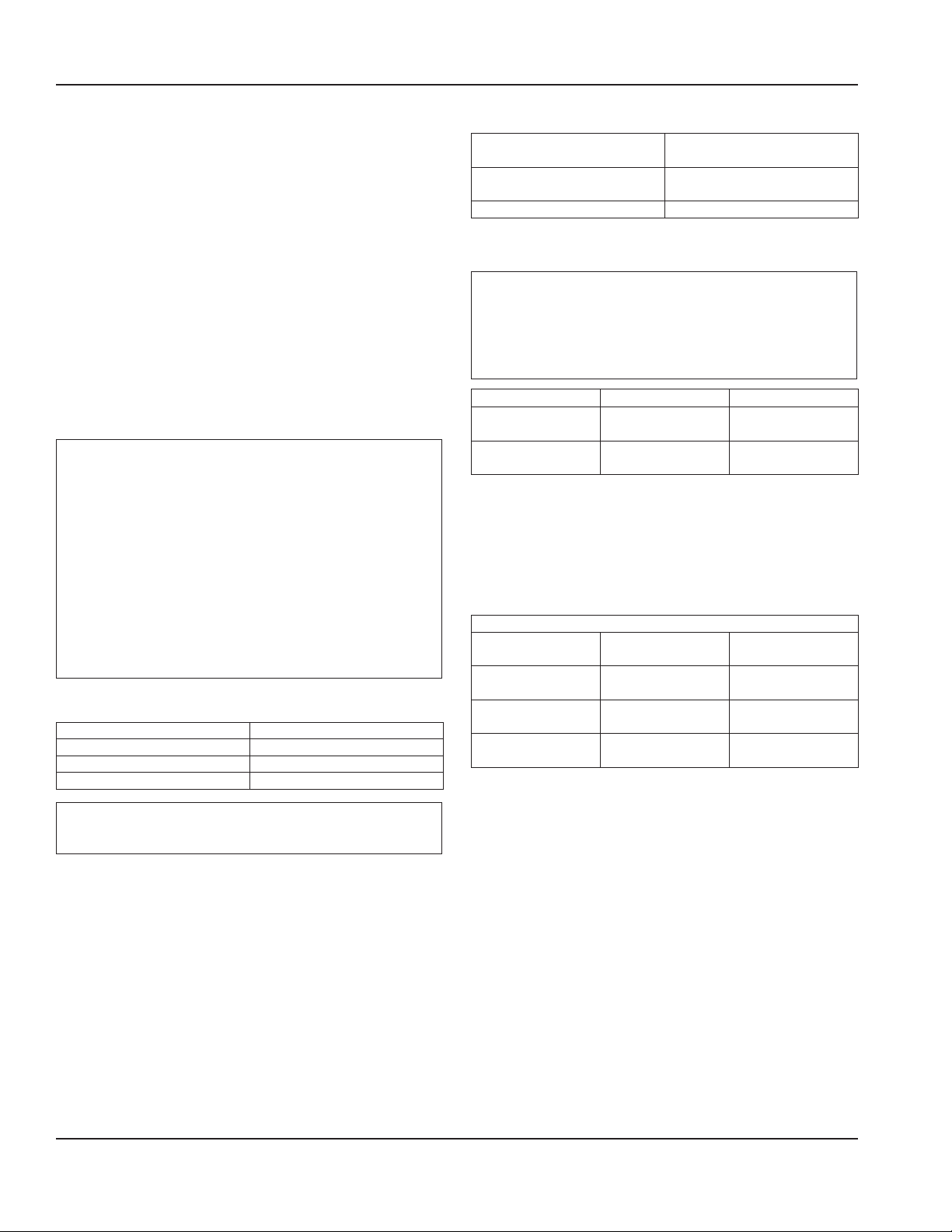
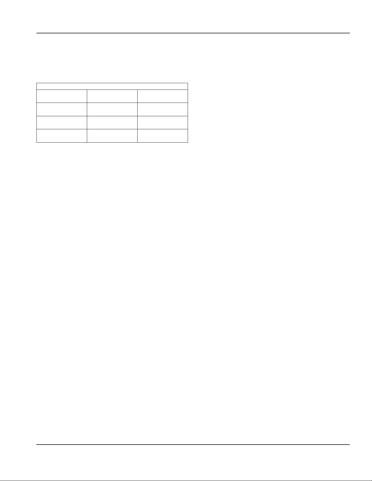
CAPACITY & WEIGHT
Ice Capacity HP Max Product
BinLoad
Lower Cabinet – 1/5 19.8 lbs
(9 kg)
Ice Maker 310 lbs
1/2 –
(141 kg)/24 hr.
Bin Storage
30 lbs (14 kg)
Shipping
Weight
606 lbs
(275 kg)
Crated
Empty Weight Full Weight
492 lbs
(223kg)
Unpacked
No Ice/
656 lbs
(298kg)
WithIce/
Product
Product
Part Number 9291386 6/14 7
Page 8
General Information Section 1
PRODUCT DELIVERY LOCATION
The location selected for the Blend-In-Cup Beverage System
must meet the following criteria.
• The air temperature must be at least 40°F (4°C), but
must not exceed 90°F (32°C), climate class 4.
• The location must not be near heat-generating
equipment or in direct sunlight and must be protected
from weather.
• Plain or Chilled Inlet Water Temperature:
min/max = 40°F / 90°F (4°C / 32°C).
• Always use the water supply line supplied when
installing this appliance. Never reuse an old supply line.
• Verify floor of install location is within 1/2" (1.3 cm) of
level front to back, side to side.
• Keep equipment area clear of combustible material.
Warning
n
Carbon Dioxide (CO2) displaces oxygen. Exposure to a
high concentration of CO2 gas causes tremors, which
are followed rapidly by loss of consciousness and
suffocation. If a CO2 gas leak is suspected, particularly
in a small area, immediately ventilate the area before
repairing the leak. CO2 lines and pumps must not be
installed in an enclosed space. An enclosed space can
be a cooler or small room or closet. This may include
convenience stores with glass door self serve coolers. If
you suspect CO2 may build up in an area, venting of the
B-I-B pumps and / or CO2 monitors must be utilized.
Clearances
Top 18" (46 cm)
Sides 6" (15 cm)
Back 6" (15 cm)
Front 30" (76 cm)
Warning
n
Do not obstruct machine vents or openings.
Heat of Rejection
Model Heat of Rejection
BTU/h
All Single & Dual Spindle Base
(Cabinet 1)
Ice Maker (Cabinet 2) 5150
2100
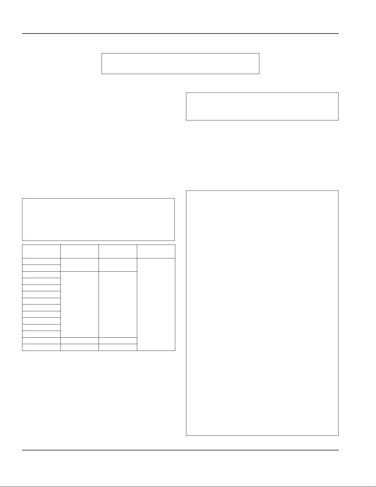
REFRIGERANT CHARGE
Important
Due to continuous improvements, this information is
for reference only. Please refer to the serial number tag
to verify electrical data. Serial tag information overrides
information listed on this page.
R-290 Models R-404A Models
Lower Cabinet
(Cabinet 1)
Ice Maker
(Cabinet 2)
R290 ICE MAKER
Acceptable incoming water temperature range is 40°F (4°C)
to 90°F (32°C). Optimum Range is 45°F (7°C) to 50°F (10°C)
(Target 50°F [10°C], results based on ARI capacity testing @
70°F [21°C] air temperature).
Air Temperature/
Water Temperature
70°/50°F
(21°/10°C)
90°/70°F
(32°/21°C)
110°/100°F
(43°/38°C)
NOTE: If chilled water is being used, depending on the
incoming Water Temp, the use of a chiller can drive an
increase in ice capacity between 50 lbs (23 kg) and 125 lbs
(57 kg) per day.
4.75 oz.
(134.7 g)
3.17 oz.
(90 g)
Ice Production
24 Hour Ice
Production
410 lbs
(186 kg)
343 lbs
(156 kg)
270 lbs
(122 kg)
12 oz.
(339 g)
16 oz.
(454 g)
kWh/100 lbs
(45 kg)
4.21
5.24
6.93
8 Part Number 9291386 6/14
Page 9
Section 1 General Information
R404A ICE MAKER
Acceptable incoming water temperature range is 40°F (4°C)
to 90°F (32°C). Optimum Range is 45°F (7°C) to 50°F (10°C)
(Target 50°F [10°C], results based on ARI capacity testing @
70°F [21°C] air temperature).
Ice Production
Air Temperature/
Water Temperature
70°/50°F
(21°/10°C)
90°/70°F
(32°/21°C)
100°/90°F
(38°/32°C)
24 Hour Ice
Production
430 lbs
(195 kg)
325 lbs
(147 kg)
270 lbs
(122 kg)
kWh/100 lbs
(45 kg)
4.927
6.912
8.568
NOTE: If chilled water is being used, depending on the
incoming Water Temp, the use of a chiller can drive an
increase in ice capacity between 50 lbs (23 kg) and 125 lbs
(57 kg) per day.
Part Number 9291386 6/14 9
Page 10
General Information Section 1
ELECTRICAL
Warning
n
All wiring must conform to local, state and national codes.
Minimum Circuit Ampacity
The minimum circuit ampacity is used to help select the
wire size of the electrical supply. (Minimum circuit ampacity
is not the Blend-In-Cup Beverage System’s running amp
load.) The wire size (or gauge) is also dependent upon
location, materials used, length of run, etc., so it must be
determined by a qualified electrician.
Voltage
A dedicated electrical circuit is required, a power cord
is provided with all units. Some models are available in
different voltages and may be equipped with a different
plug. Refer to Blend-In-Cup Beverage System Model/Serial
Plate for voltage/amperage specifications.
Minimum Circuit Amperage Chart
Important
Due to continuous improvements, this information is
for reference only. Please refer to the serial number tag
to verify electrical data. Serial tag information overrides
information listed on this page.
Model Voltage/Cycle/
Phase
MB-8-1
MB-8-2
MB-8-1A
MB-8-2A
MB-8-1D
MB-8-2D
MB-8-1E
MB-8-2E
MB-8-1P
MB-8-2P
MB-8-1U
MB-8-2U
MB-8-1BF 230/60/1 6.4
MB-8-1PP 230-240/50/1 6.4
120/60/1 16.0
220/50/1 8.7
Total Amps Breaker Size
(Max)
20A
Grounding Instructions
Warning
n
The machine must be grounded in accordance with
national and local electrical codes.
This appliance must be grounded. In the event of
malfunction or breakdown, grounding provides a path
of least resistance for electric current to reduce the
risk of electric shock. This appliance is equipped with a
cord having an equipment-grounding conductor and
a grounding plug. The plug must be plugged into an
appropriate outlet that is properly installed and grounded
in accordance with all local codes and ordinances.
Warning
n
When using electric appliances, basic precautions must
always be followed, including the following:
A. Read all the instructions before using the
appliance.
B. To reduce the risk of injury, close supervision
is necessary when an appliance is used near
children.
C. Do not contact moving parts.
D. Only use attachments recommended or sold by
the manufacturer.
E. Do not use outdoors.
F. For a cord-connected appliance, the following
must be included:
• Do not unplug by pulling on cord. To unplug,
grasp the plug, not the cord.
• Unplug from outlet when not in use and
before servicing or cleaning.
• Do not operate any appliance with a
damaged cord or plug, or after the appliance
malfunctions or is dropped or damaged in
any manner. Contact the nearest authorized
service facility for examination, repair, or
electrical or mechanical adjustment.
G. Follow applicable lock out tag out procedures
before working on equipment.
H. Connect to a properly grounded outlet only. See
Grounding Instructions.
10 Part Number 9291386 6/14
Page 11
Section 1 General Information
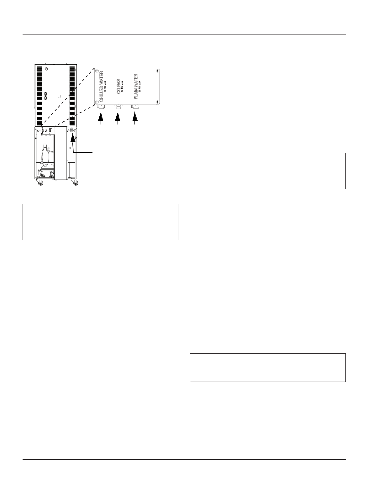
AIR / CO2, PLAIN & CHILLED WATER INLETS
Connections Drain
Warning
n
Connect to a potable water supply only.
SYSTEM PRESSURES
Plain & Chilled Water
Important
Requires the pressure measurement to be taken only
when rinse water is spraying (flowing conditions) in a
blender chamber.
• Plain Water Supply Pressure must be capable of
continuously suppling a minimum of 35 psi (241 kPa,
2.41 bar) during flowing conditions.
• If a separate chilled water source is used, the chilled
supply pressure needs to be a minimum of 35 psi
(241kPa, 2.41 bar) at no flow conditions.
Important
Water pressure affects the blender area cleaning, a
water booster may be required if pressure is too low.
Air / CO
2
Important
Requires the pressure measurement to be taken only
when a product pump is being activated (product
pump during flow conditions).
• Use supplied 3/8" (.95 cm) panel-mounted hose barb
and 6' (1.8 m) of beverage tubing to connect labeled
coupling body fitting(s) on back of unit for each supply
connection.
• Do not connect either water connection to a hot water
supply. Be sure all hot water restrictors installed for
other equipment are working. (Check valves on sink
faucets, dishwashers, etc.)
• Install a water shut-off valve in the water line at the rear
of the machine.
• Insulate water inlet lines to prevent condensation.
Hard Water
In areas where the water is highly concentrated with
minerals the water should be tested by a water treatment
specialist, and the recommendations of the specialist
regarding filtration and/or treatment should be followed.
• Supply must be capable of 35 psi (241 kPa, 2.41 bar)
minimum during flowing conditions, measured at
the unit Air/CO2 regulator. See “How to Check Air/CO2
Pressure” on page 76.
• Supply to the unit not to exceed 50 / 80 psi (345 /
552 kPa, 3.45 / 5.52 bar) maximum during no flow
conditions.
DRAIN CONNECTIONS
• Connect supplied 1" ID hose to hose-barb connection
on machine.
• Drain lines must have a 1.5 inch drop per 5 feet of run
(2.5 cm per meter), and must not create traps.
• The floor drain must be large enough to accommodate
drainage from all drains.
• An air gap is included in the design of the machine for
backflow prevention. Plumb to local code.
Part Number 9291386 6/14 11
Page 12

General Information Section 1
THIS PAGE INTENTIONALLY LEFT BLANK
12 Part Number 9291386 6/14
Page 13
Section 2
Installation
Step-by-Step Installation
These instructions are provided to assist the qualified
installer. Contact your Manitowoc Foodservice Service
Agent or call Manitowoc Foodservice for information
regarding start-up services.
Important
Failure to follow these installation guidelines may affect
warranty coverage.
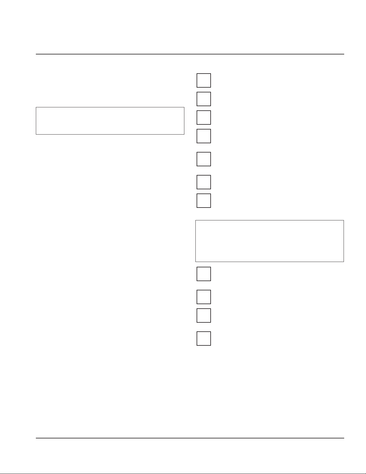
PREINSTALLATION CHECKLIST
Keep product bags in a cooler at least 24 hours
prior to installation.
Any damage should be noted and reported to the
delivering carrier immediately.
Check the lower portion of the unit to be sure
casters are not bent.
Visually inspect the refrigeration package,
compressor compartment housing. Be sure lines
are secure and base is still intact.
Inspect installation location behind the BIC for
electrical outlet location, CO2, water hose fittings,
and shutoff.
Check voltage at outlet dedicated for BIC.
Verify floor of install location is within 1/2” (1.3 cm)
of level front to back, side to side and all casters are
touching the floor.
Warning
n
The mass of this appliance will allow it to move
uncontrolled on an inclined surface. Adequate means
must be provided to prevent uncontrolled movement
at all times.
Remove the side panels from the unit to make the
board connections, Air/CO2 and Water Regulator
gauges accessible.
Check that board connections are secure and did
not vibrate loose during shipment.
Remove steel top panel. Check that the black chute
cover is sitting securely on the chute. The ice maker
will not operate properly if it is out of place.
Check that both micro switches are in line with the
motor above the blenders.
Part Number 9291386 6/14 13
Page 14
Installation Section 2
CONNECTIONS
* Chilled
Water
Drain
OUT
Air/
Plain
CO2
IN
Water
IN
IN
* Chilled Water Inlet only
available on units with
this feature
Rear of the Unit
Important
Leave enough slack in the water/CO2/drain lines to allow
access to the rear of the machine without disconnecting
the lines.
Water
1. Connect the Plain and Chilled (if used) water lines quick
disconnect fittings and verify the water regulators
are set to 35 psi (241 kPa, 2.41 bar). The Plain Water
regulator is located on the left side of the unit and the
Chilled Water regulator is located at the rear top. Final
during-flow settings will be made once the unit is in
operation. See “Start-Up & Cleaning” on page 15.
Air/CO2
2. Connect Air/CO2 line quick disconnect fitting. Verify the
Air/CO2 regulator on the left side of the unit is set to
35psi (241 kPa, 2.41 bar). Final during-flow settings will
be made once the unit is in operation.
Important
Regulators are factory set but will need to be checked
and possibly adjusted under flowing conditions once
the unit is operational.
3. Confirm correct orientation of Water and Air/CO2
fittings.
4. Coil excess tubing and secure with tie straps.
Drain
5. Route drain line (minimum 1” ID) to drain, maintaining
a 2” (51 mm) air gap. Cut to proper length if needed (do
not leave loops in drain). See “Drain Connections” on
page 11.
Electrical
6. If all electrical and grounding requirements have
been followed (See “Electrical” on page 10 & See
“Grounding Instructions” on page 10) proceed to
insert electrical plug from BIC into wall receptacle.
7. Turn power and compressor switches, on the left-hand
side of the unit and the rear, to the ON position.
8. The touch screen should energize and inform the user
to perform Zone 2 & 3 cleaning before the unit can be
put into operation.
Important
Do not add product to the machine until cleaning and
sanitizing are complete.
14 Part Number 9291386 6/14
Page 15
Section 2 Installation
INSTALLATION CHECKLIST
Review before proceeding to Start-Up & Cleaning.
Has all of the internal packing been removed?
Have all of the electrical, water and CO2
connections been made?
Is there proper clearance around the machine for
air circulation?
Is the machine grounded / polarity correct?
Has the machine been installed where the
incoming water temperature will remain in the
range of 40°F / 90°F (4°C / 32°C)?
Have the regulators been set to 35 psi (241 kPa,
2.41 bar)?
Have the blender door(s) sensor position(s) been
checked?
Have the Compressor and Power switches been
turned to the ON position?
STARTUP & CLEANING
1. Clean and sanitize the Blend-In-Cup machine by
following the on-screen instructions.
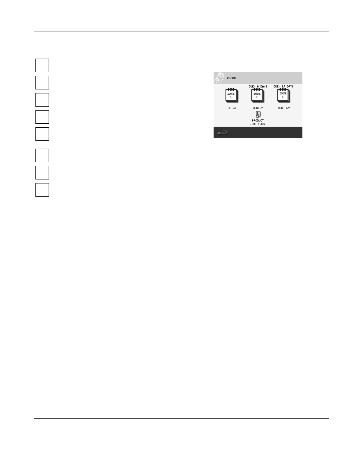
Cleaning Touch Screen
See “Weekly Cleaning - Zone 2” on page 40, “Monthly
Cleaning - Zone 3” on page 51. By doing so, the
following will have been completed:
A. All beverage lines, ice maker, dispense area, and
blender chambers, cleaned and sanitized.
B. Water run through the drain to verify it is draining
properly.
C. Product bags retrieved from walk-in cooler,
installed into the product bins and placed
into their proper location in the cabinet. See
“Procedure to Install a Product Bag” on page 30
& “Assigning Flavors” on page 26.
D. All product lines primed and ready for use.
NOTE: During the cleaning process is an ideal time to verify
pressure regulator settings during flowing conditions.
E. Verify the Plain Water regulator is set correctly
during blend chamber cleaning, the regulator
should maintain 35 psi (241 kPa, 2.41 bar) under
flowing conditions.
F. Verify the Air/CO2 regulator is set correctly during
product line cleaning, the regulator should
maintain 35 psi (241 kPa, 2.41 bar) under flowing
conditions.
NOTE: The Chilled Water Regulator needs to be a minimum
of 35 psi (241 kPa, 2.41 bar) at no flow conditions.
Part Number 9291386 6/14 15
Page 16
Installation Section 2
Label
2. Add labels to product bins, put labels in correct place.
3. Add labels anywhere else on the unit required.
Software
4. Load recipes. See “Loading Recipes” on page 32.
5. Verify correct drinks and flavors are available.
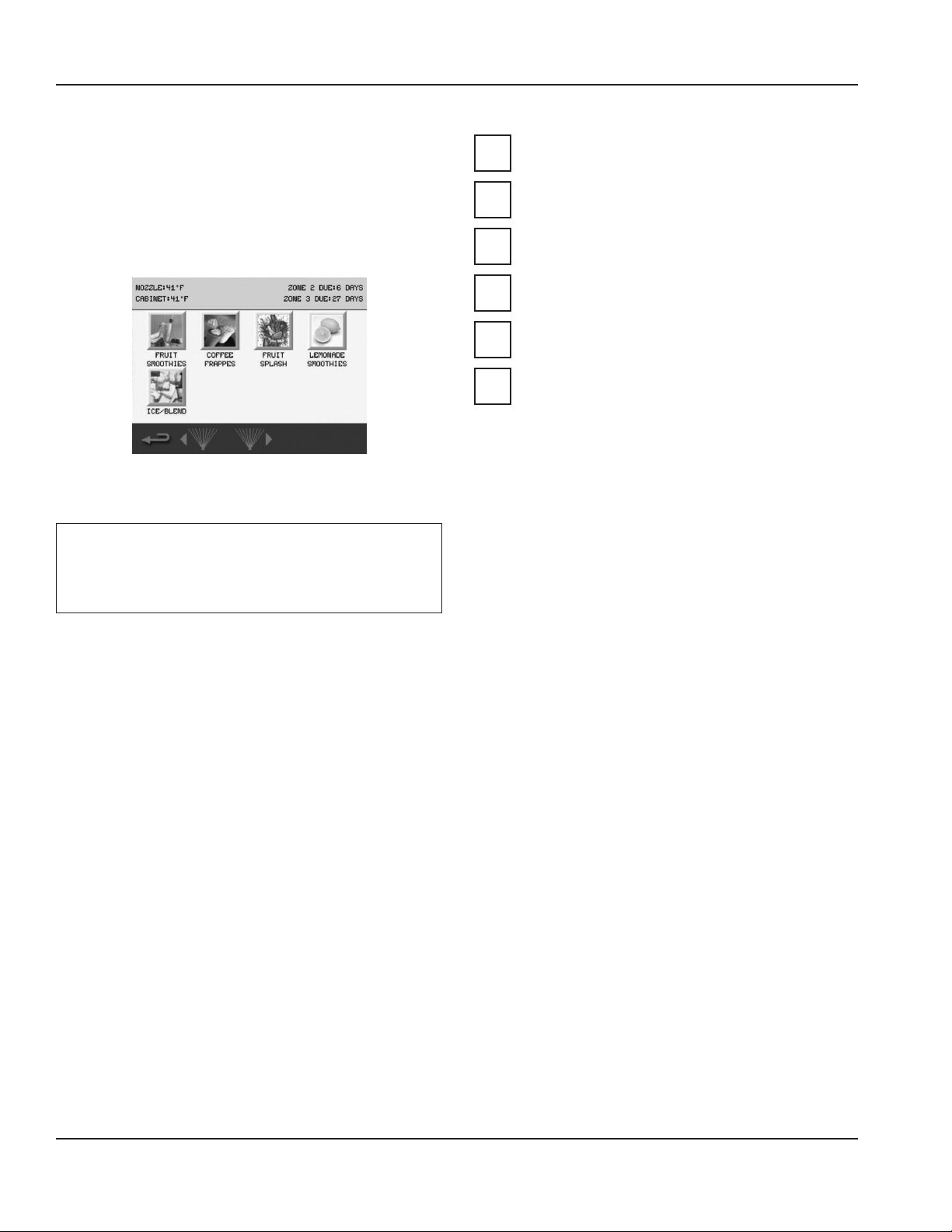
Drink Selection Screen
(Drink choices will vary depending on loaded recipe file)
Calibrate
Important
Allow cabinet to reach operating temperature 36°F –
38°F (2°C – 3°C) before calibrating. Calibration will be
inaccurate if performed above operating temperatures.
POST INSTALLATION CHECKLIST
Has the machine been properly sanitized?
Has each flavor been installed and primed?
Have the Air/CO2 and Plain water regulators been
correctly set during flowing conditions?
Is the machine cycling ON/OFF on the temperature
control?
Has the owner/operator been instructed regarding
maintenance procedures?
Has the owner/operator completed the warranty
registration card?
6. Product calibration can be performed once operating
temperature has been reached. See “Calibration
Procedure” on page 27 for step-by-step calibration
instructions. Once completed, the Blend-In-Cup
machine is ready for use.
7. Reinstall top and side panels.
8. Push BIC into place.
9. Verify the unit is level and shim if necessary.
DEMONSTRATE
10. Demonstrate using the Interface. See “Touch Screens”
on page 19.
11. Demonstrate how to make drink. See “Procedure to
Make a Drink” on page 22.
12. Demonstrate Manager Menu options, using the
default password. (The password can be changed.) See
“Manager’s Menu Screen” on page 25.
13. Set date and time to activate warranty.
14. Complete start-up form, sign, and have store manager
sign form. (Fax to number on form.)
16 Part Number 9291386 6/14
Page 17
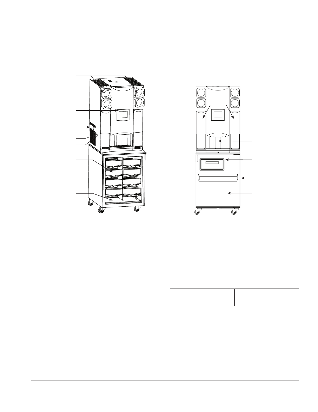
Component Identification
Cup Dispensers
Touch Screen
Section 3
Operation
Blending
Station Doors
Plain Water & CO
Regulator Gauges
Power Switch
Product Bins
Pull Out Tray
2
USB Port
Sequence of Operation
NORMAL OPERATION
Drink Selection screen appears after power-up of the unit.
Operator presses one of the drink type buttons on the Drink
Selection screen, and the Flavor Options screen appears.
Once a flavor is selected, the Size screen appears. See
“Procedure to Make a Drink” on page 22.
Next the drink preparation sequence commences. If add-ins
are required for the drink, the user will be prompted. Here,
according to the drink size selected and when initiated
through the touch screen, the machine dispenses product
and ice into the cup in the dispense area. The cup is then
placed into an available blend chamber.
Product
Dispense Area
Whip Cream Door
(Optional)
Syrup Rail & Dividers
(Optional)
Cabinet Door
(Can be configured for
Right- or Left-Hand)
With the blend chamber door closed and after “Start Mixer”
is selected on the touch screen, the machine blends the
drink for the correct time at the proper blender speed. If
add-ins are required for the drink after blending, the user
will be prompted.
After the drink is removed and the operator closes the
blend chamber door, the automatic rinse of the blender
initiates. The Drink Selection screen re-appears.
Default Temperature
ControlSetting
36°F/2°C set point
2°F/1°C differential
controlled by software
Part Number 9291386 6/14 17
Page 18
Operation Section 3
ICE MAKING
Ice Machine Switches - Rear of the Unit
Compressor
Switch
Power
Switch
The ice machine will not start until:
1. The compressor rocker switch is moved to “ON”.
2. Ice does not contact the bin level sensor.
3. The water reservoir is full of water.
With power supplied and the compressor rocker switch in
the ON position, the gear motor and refrigeration system
start. The float valve controls the water inlet valve and water
level. The freeze cycle ends when the ice contacts the ice
bin level sensor.
NOTE: Ice machines use an auger to remove ice from the
evaporator. Occasional noises (creaks, groans, squeaks, or
pops) are a normal part of the ice making process.
18 Part Number 9291386 6/14
Page 19
Section 3 Operation
Touch Screens
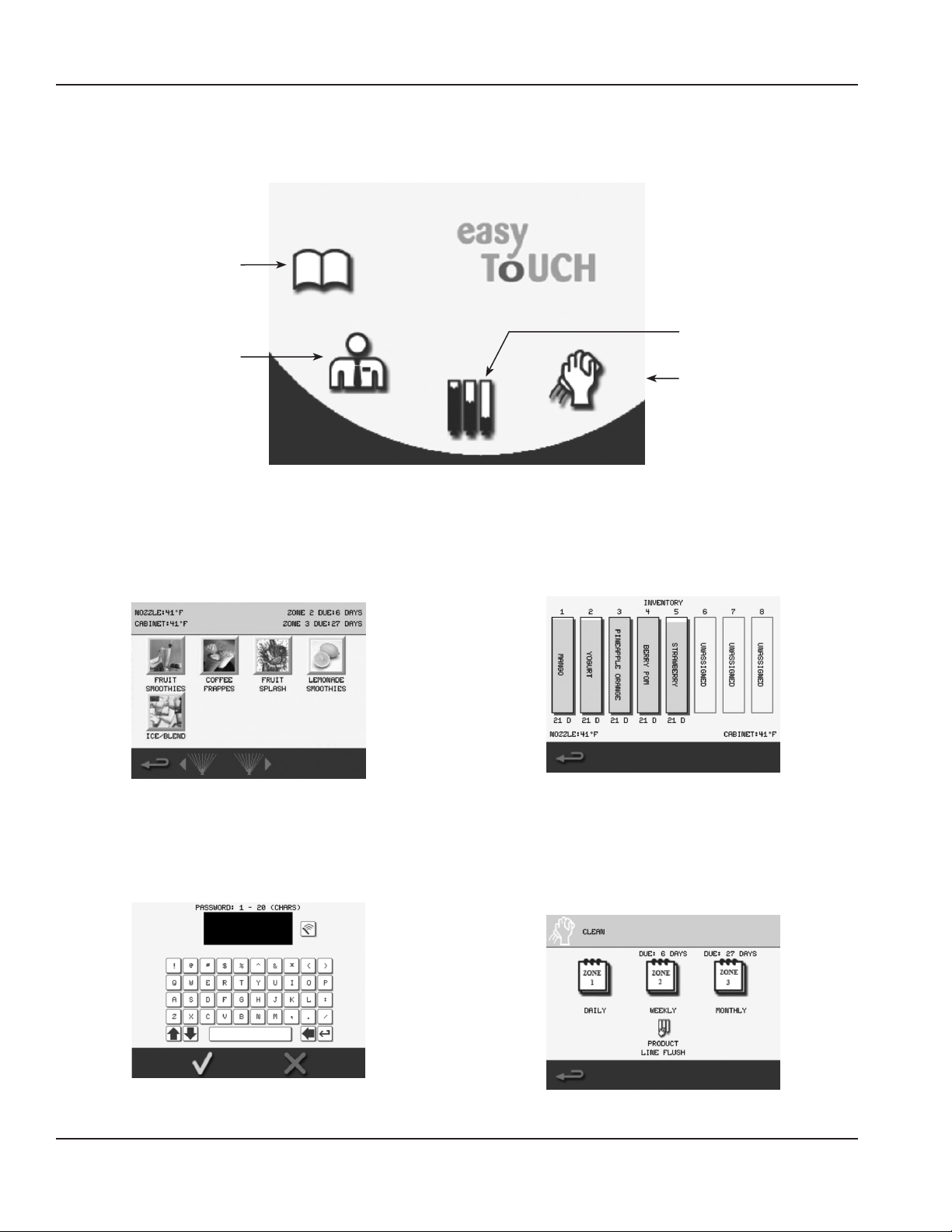
The “easy ToUCH” screen has four selections. One is for the drink making procedure: Drink Selection displays by default at
start-up. The Manager’s Menu is for accessing the machine’s settings. Inventory is for product information and Cleaning is for
routine maintenance of the machine.
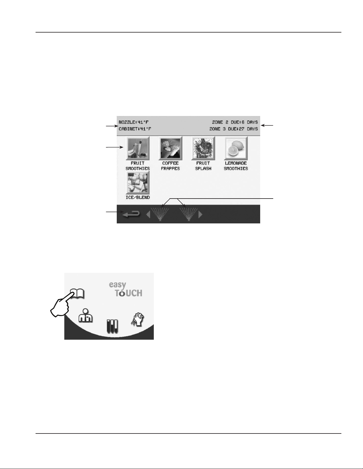
DRINK SELECTION SCREEN
The Drink Selection screen appears on power-up (except where clean/sanitize limitations have been exceeded, in which
case the Cleaning screen appears). See “Maintenance” on page 33 for Daily, Weekly and Monthly cleaning/sanitization. The
Drink Selection screen’s primary function is to select a drink to make or to access the Main Menu.
Nozzle & Cabinet
Temperatures
Drink Categories
Go to Main
MenuScreen
How to Access
The Drink Selection screen displays by default unless
cleaning is required. This screen can also be accessed
through the main menu Book Icon.
Cleaning
Reminders
Rinse Button(s)
Icon Button Descriptions
• NOZZLE & CABINET Temperatures
Displays the current temperature for dispense point
nozzle and the refrigeration cabinet. Unit of measure
can be changed in the Manager’s Menu.
• Drink Categories
The main product categories are displayed left to right
on the Drink Selection screen. Touching a category
will display the drink flavor options available for the
category.
NOTE: Available drink selections may vary depending on
the recipe file installed.
• Main Menu Arrow
Navigates to the Main Menu screen.
(See “Main Menu Screen” on page 24)
• Cleaning Reminders
Displays the time remaining in days until ZONE 2
(Weekly) and ZONE 3* (Monthly) cleaning is required.
* If equipped with this feature.
• Rinse Button
Press to rinse the left or right blender chambers. Blend
chamber door(s) must be closed.
Part Number 9291386 6/14 19
Page 20
Operation Section 3
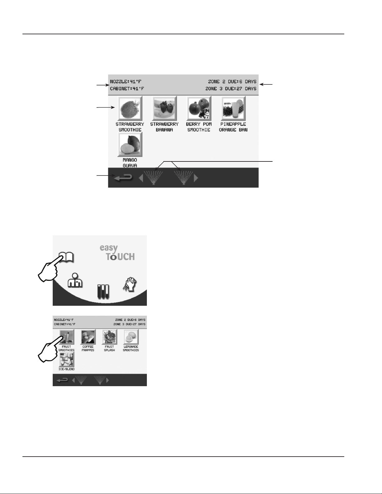
FLAVOR SELECTION SCREEN
The Flavor Selection screen appears after a Drink Selection has been made. Flavor options will vary depending on what
recipes are configured on the unit. This screen’s primary function is to select a drink flavor.
Nozzle & Cabinet
Temperatures
Drink Flavor
Buttons
Go Back One
Screen
How to Access
The Flavor Selection screen displays after a drink selection
has been made from the Drink Selection screen.
Cleaning
Reminders
Rinse Button(s)
• Drink Flavor Buttons
Flavor choices for the drink type that was selected.
• Yellow Border
If any of the drink’s ingredients will expire soon, the
yogurt has expired, or there is less than 10% left in
the product bag. Check the Product Inventory Screen
for exact amount of product remaining.
(See “Product Inventory Screen” on page 29)
• Red Border
Product expired, flavor selection unavailable. Will
need to replace product bag. (See “Procedure to
Install a Product Bag” on page 30)
NOTE: Available flavor selections may vary depending
on the recipe file installed.
• Back Arrow
Navigates to previous Drink Selection screen.
(See “Drink Selection Screen” on page 19)
• Cleaning Reminders
Displays the time remaining in days until ZONE 2
(Weekly) and ZONE 3* (Monthly) cleaning is required.
* If equipped with this feature.
• Rinse Button
Press to rinse the left or right blender chambers. Blend
Icon Button Descriptions
chamber door(s) must be closed.
• NOZZLE & CABINET Temperatures
Displays the current temperature for dispense point
nozzle and the refrigeration cabinet. Unit of measure
can be changed in the Manager’s Menu.
20 Part Number 9291386 6/14
Page 21
Section 3 Operation
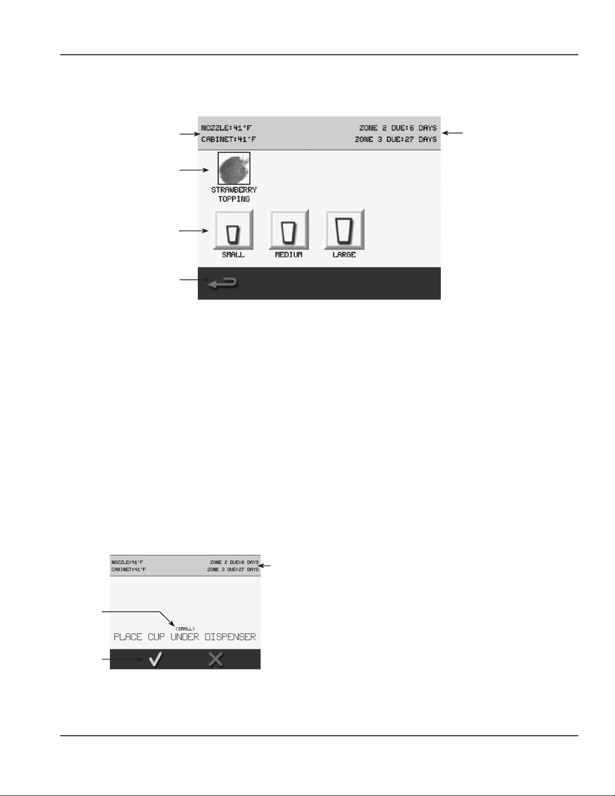
SIZE SCREEN
The Size screen appears after a drink flavor has been chosen from the Flavor Selection screen. This screen’s primary function
is to select size and make a drink. Optional Add-Ins are also performed through this screen if the drink requires them.
Nozzle & Cabinet
Temperatures
Add-in Topping
Drink Size
Selection Buttons
Go Back One
Screen
Icon Button Descriptions
• NOZZLE & CABINET Temperatures
Displays the current temperature for dispense point
nozzle and the refrigeration cabinet. Unit of measure
can be changed in the Manager’s Menu.
• Add-Ins
These are not functioning buttons, only a graphic
representation of the add-in used when making the
selected drink. The screen will prompt the user when
the add-in is to be added to the drink.
NOTE: Not all drinks have an add-in. Drink add-ins may
vary depending on the recipe file installed.
Cleaning
Reminders
With the correct cup in place, press the green check to
dispense product/ice into the cup or press the red X to
cancel and return to the Size Selection screen.
(See “Procedure to Make a Drink” on page 22)
• Back Arrow
Navigates to previous Flavor Selection screen.
(See “Flavor Selection Screen” on page 20)
• Cleaning Reminders
Displays the time remaining in days until ZONE 2
(Weekly) and ZONE 3* (Monthly) cleaning is required.
* If equipped with this feature.
• Drink Size Buttons
Press a drink size (SMALL, MEDIUM, or LARGE) to start
the drink making process. Once one is selected, the
screen will prompt the user to place the correct cup size
in the dispense area.
Cleaning
Reminders
Cup Size
Required
Dispense
Product
Dispense Prompt Screen
Part Number 9291386 6/14 21
Page 22
Operation Section 3
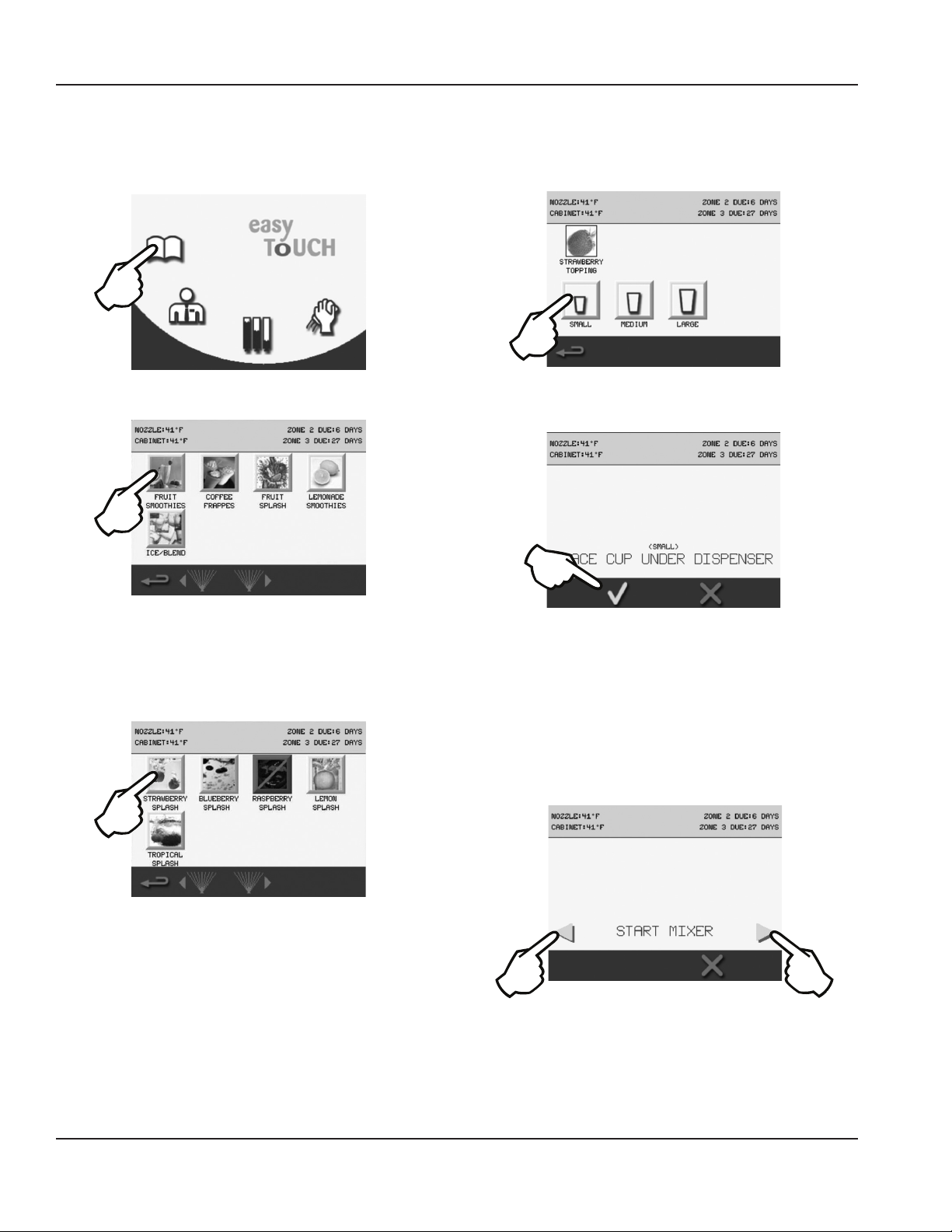
Procedure to Make a Drink
NOTE: Ice must be present in the ice hopper, product must be connected and primed to produce a drink.
1. Press the Open Book icon.
2. Select a category of drink recipes.
3. Specific drink combinations are displayed on the next
screen. If a drink is not available, it will be highlighted
with a red square around it. Unavailable flavors have
expired and will need to be replaced. (See “Procedure
to Install a Product Bag” on page 30)
4. Drink size is the next selection.
5. Place cup under center dispenser and press the green
check.
6. As the flavor dispenses into the cup, the screen will
display DISPENSING.
7. If Add-in ingredients need to be manually added, the
screen will give specific directions. More ingredients
may be required later, follow the screen directions.
8. Choose an available mixer, place the cup into the
blender chamber, and shut the door. Press the
corresponding right or left flashing green/blue arrow.
NOTE: Single mixer unit will only display a right arrow. Press
the red X to cancel.
22 Part Number 9291386 6/14
Page 23
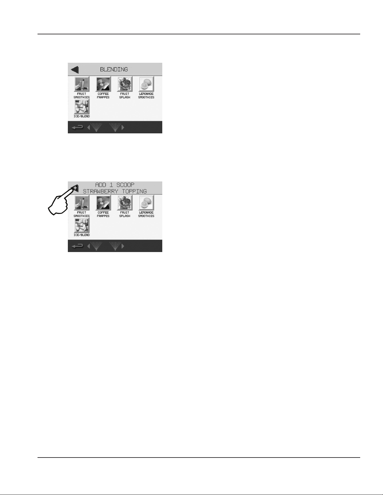
Section 3 Operation
9. While the drink is mixing, the top of the screen will read
BLENDING.
NOTE: On dual mixer units, a second drink can be selected
and blended simultaneously.
10. Follow all drink specific screen directions for add-ins if
necessary and press the flashing arrow if prompted.
11. When the blender is done mixing, open the door and
remove the drink. The blending station will go through
a rinse cycle after the door is closed again.
12. The blend station will not be available again until the
door is closed and the rinse cycle is completed.
Part Number 9291386 6/14 23
Page 24
Operation Section 3
MAIN MENU SCREEN
Accessed primarily though the Drink Selection screen, this screen’s primary function is to provide access to all other
procedures and adjustments that can be performed on the unit.
Drink Recipes
Menu
Inventory
Managers Menu
Cleaning
Category Icon Descriptions
• Drink Recipes Menu
Displays the Drink Selection screen.
(See “Drink Selection Screen” on page 19)
• Managers Menu
Displays a Password Keypad screen. When password is
correctly entered, a menu of protected information for a
manager will display.
(See “Manager’s Menu Screen” on page 25)
• Inventory
Displays the remaining percentage of product in each
bag, and NOZZLE and CABINET temperature readings.
(See “Product Inventory Screen” on page 29)
• Cleaning
Displays the Cleaning screen and gives the options for
ZONE 1 (Daily), ZONE 2 (Weekly), or ZONE 3* (Monthly)
cleaning and PRODUCT LINE FLUSH.
(See “Maintenance” on page 33)
* If equipped with this feature.
24 Part Number 9291386 6/14
Page 25

Section 3 Operation
MANAGER’S MENU SCREEN
Accessed though the Main Menu screen, this screen’s primary function is to provide on-screen access to Manager-only
functions.
How to Access
Password
Display Area
Password
Input Keypad
Accept
Password
Clear Password
Display
Cancel
Manager Menu Features
After selecting Manager’s Menu icon from the Main Menu,
Manager Menu Screens
the Password Keypad screen appears. The manager screens
are password protected. Enter the Manager’s pass code
using the QWERTY keypad, then press the green check to
accept.
After typing in the correct password, Language, Date/Time,
Temperatures, Edit Password, Configure Slots, Updates,
Auto Wash Timer and Service screens are accessible. When
the manager screens are inactive for a time period, the
screen will return to the drink menu.
Important
Do not change the language, edit the password or
configure the slots unless instructed to do so by the
factory. The service screen is password protected,
contact the factory for access.
• Manager Screen 1
• LANGUAGE
• DATE & TIME Settings
• TEMPERATURES
• EDIT PASSWORD
• CONFIGURE SLOTS
• Manager Screen 2
• UPDATES
• AUTO WASH TIMER
• SERVICE (Password Protected Sub Screens)
• Manager Screen 3
This screen displays all current software versions on the
unit.
• Manager Screen 4
This screen displays the drink counter.
Part Number 9291386 6/14 25
Page 26

Operation Section 3
Assigning Flavors
1. From the Main Menu select the Manager icon.
2. Type in the password.
2
3
3. Select the green check.
4. Select CONFIGURE SLOTS.
6. Select a slot you want to assign a flavor to.
7. Select from available flavors.
NOTE: Available flavors will vary depending on the recipe
file that is loaded on the machine. Select ASSIGN FLAVOR.
• Screen will return to the Select Slot screen.
• The flavor name will now display and the slot will be
highlighted green.
8. Continue to select slots and flavors until all slots are
assigned.
5. Press the SLOT FLAVOR icon.
9. Select the red X when finished to return to the
Configure Slots screen. Select the return arrow twice to
return to the Main Menu.
26 Part Number 9291386 6/14
Page 27

Section 3 Operation
CALIBRATION PROCEDURE
Gather the following supplies
Important
Prior to performing calibration, check for empty product
bags, refrigerate product bags for 24 hours, and if Zone
2 cleaning has just been completed, wait 1 hour.
Kitchen Scale
Empty & Clean Cups
1. From the Main Menu, select the Manager icon.
5. Select a flavor, water or ice to calibrate.
6. Follow the on-screen instructions and do the following:
• Get a scale.
• Tare empty cup weight.
• Position an empty cup for dispense.
2. Enter the manager’s password.
3. Select CONFIGURE SLOTS.
4. Select CALIBRATE FLAVOR.
• Press green check when ready.
• Wait until dispensing is done.
• Weigh cup.
NOTE: Flavor and water target is 4 oz. (113 grams). Ice target
is 6 oz. (170 grams).
• Tap button to enter weight.
Part Number 9291386 6/14 27
Page 28

Operation Section 3
7. The Enter Weight screen will appear.
A. Enter the cup weight using the number pad.
A
B
B. Select the green check when done to continue.
NOTE: If the weight entered was not 4 oz. (113 grams)
for a flavor/water or 6 oz. (170 grams) for ice, the unit will
electronically adjust the dispense calibration based on
the weight entered to obtain the correct target dispense
weight. No mechanical adjustments are required.
8. The calibration screen will display again with the
weight entered on the previous screen.
A. If the weight displayed is incorrect, press the
button again and re-enter weight.
10. The newly calibrated slot will be highlighted in green.
A. Choose another flavor, water or ice to calibrate.
A
B
B. Or press the red X to return to the CONFIGURE
SLOTS Screen. From there press the back arrow
twice to reach the Main Menu and place the unit
into operation.
B
A
B. Press green check when done to save and
complete calibration for the slot.
9. The CALIBRATION COMPLETE screen will display.
• Press green check to return to the Calibration Slot
Choice screen.
28 Part Number 9291386 6/14
Page 29

Section 3 Operation
PRODUCT INVENTORY SCREEN
This screen’s primary function is to provide visual product inventory information for the user. The Product Inventory screen is
normally accessed through the Main Menu.
Product Bin Number
Product Inventory
Bar Graph
Unassigned
Product Bin
Days Until
Expiration
Nozzle
Temperature
Main Menu
Cabinet
Temperature
The inventory screen visually displays levels for all flavors. Underneath each flavor is the time remaining until the flavor
expires in days. NOZZLE and CABINET temperatures are also on the inventory screen. When a flavor is touched on the screen,
the instructions to replace a product bag will begin. (See “Procedure to Install a Product Bag” on page 30)
How to Access
• UNASSIGNED
If UNASSIGNED is displayed below the product bin
number, no product is currently assigned to the bin.
• NOZZLE Temperature
Displays the current temperature near the dispense
point. Can be set to Celsius or Fahrenheit in the
Manager’s Menu. (See “Manager’s Menu Screen” on page
25)
Icon Button Descriptions
• Product Bin Number
Displays the product bin number the Product Inventory
Bar Graph represents.
• Product Inventory Bar Graph
Product inventory tracking estimates the remaining
flavoring in each product’s bag in the reach-in
compartment in 5% increments.
• Back Arrow
Navigates to previous Main Menu screen.
• Days Until Expiration
Displays the number of days remaining until the
product bag expires. Pressing the corresponding
product bar graph will access the Replace Product
screen, displaying the steps to follow for replacement.
(See “Procedure to Install a Product Bag” on page 30)
• Green Bar
Product inventory is above 10% and not near
expiration.
• Yellow Bar
Product inventory has fallen below 10% or less than
24 hours until expiration, a message appears on the
Drink Selection screen for the affected drink(s).
• Red Bar
If the bar representing a product’s inventory level is
red, the bag is empty or expired. Replace product.
(See “Procedure to Install a Product Bag” on page
30)
Part Number 9291386 6/14 29
Page 30

Operation Section 3
• CABINET Temperature
Displays the current temperature in the refrigeration
cabinet. Can be set to Celsius or Fahrenheit in the
Manager’s Menu. (See “Manager’s Menu Screen” on page
25)
Procedure to Install a Product Bag
1. From the Main Menu touch the Inventory icon.
2. On the Inventory screen, select the product to be
installed.
4. Press the green check to continue.
5. Position rear groove of the spout on product bag into
slot of the product bin.
Important
The spout must snap into the slot of the product bin!
6. Open the cap on the product bag and tear it off.
7. Return product bin to its position in cabinet.
8. Press the green check to continue.
9. Select inventory level from FULL BAG, PRIME FLAVOR or
NO BAG.
10. Select FULL BAG when installing a new product bag
and the Prime screen will display.
11. Place cup under dispenser and press the Prime icon to
prime the line with the new product bag, DISPENSING
will display on the screen. Repeat until product
consistently flows into the cup.
12. Press the green check to continue.
• Products with less than 10% inventory or less than 24
hours until product expires will be displayed with a
yellow bar.
• Products that are expired will be displayed with a red
bar.
3. Follow the on screen instructions.
• Remove product bin from cabinet and discard empty
bag.
• Wipe the inside of the product bin with a clean towel.
• Place new product bag with the spout facing down
into product bin.
13. Installation is now complete. The inventory bar will now
display full, green, and days until expiration will reset.
14. Select another product to be installed or return to the
previously active screen by pressing the back arrow.
Important
Resetting a product’s inventory without replacing the
product bag will cause the Product Inventory screen,
percentages, and expiration to be inaccurate.
30 Part Number 9291386 6/14
Page 31

Section 3 Operation
CLEANING SCREEN
The Cleaning screen appears after selected from the Main Menu or when prompted to perform routine cleaning. This
screen’s primary function is to perform routine cleaning and sanitation of the machine.
Cleaning
Countdown
ZONE 1
Daily Cleaning
ZONE 2
Weekly Cleaning
Main Menu
How to Access Icon Button Descriptions
• ZONE 1 - Daily Cleaning
Displays the Daily Cleaning screen and guides the user
through all daily cleaning requirements.
See “Daily Cleaning - Zone 1” on page 35.
• ZONE 2 - Weekly Cleaning
Displays the Weekly Cleaning screen and guides the
user through all weekly cleaning requirements.
See “Weekly Cleaning - Zone 2” on page 40.
• ZONE 3 - Monthly Cleaning*
Displays the Monthly Cleaning screen and guides the
user through all monthly cleaning requirements. See
“Monthly Cleaning - Zone 3” on page 51.
*If equipped with this feature.
• Back Arrow
Returns to the previous screen or Main Menu.
• Cleaning Count Down
Days left until Cleaning is required. Shown in DAY
increments, changes to HOURS when there is less than a
day (24 hours) until cleaning of the machine is required.
Resets once cleaning has been completely performed.
ZONE 3
Monthly Cleaning
PRODUCT LINE
FLUSH
Important
Once the time limit has been exceeded the machine
will no longer make a drink until cleaning has been
completed.
• PRODUCT LINE FLUSH
Displays the Product Line Flush screen and guides the
user on how to flush all product lines. See “Product Line
Flush” on page 66.
Part Number 9291386 6/14 31
Page 32

Operation Section 3
Other Operations
LOADING RECIPES
Plug in the Flash drive (above upper left corner of screen).
From the Main Menu select the Manager icon. Type in the
password and select the green check. Select the down
arrow to navigate to the next screen. Select UPDATES.
Select RECIPES. Select the UPDATE RECIPES FROM USB icon.
Verify the version to be loaded is correct, and select the
green check. Screen will display status and then UPDATE
COMPLETE.
RECOMMENDED CUPS
Although a variety of cups may work in the BIC machine,
the most success (without cup cracking) has come from
polyethylene (PETE) cups. Other varieties such as glass,
polypropylene, and thick walled styrofoam have also
proven workable. Cup thickness, material composition,
diameter and cup height play an important role in the
workability of the cup within the machine.
The following are cup general guidelines. Cups outside
these parameters may work but are not recommended.
Testing in the machine with the product will be necessary.
Contact the Multiplex team for a detailed cup evaluation.
• Cup heights between 4.25" and 7.00".
• Cup opening diameter greater than 3.50" and less than
4.18".
• Cup base diameter greater than 2.38" and less than
2.62".
• Approved Materials - PET, PET-R, Glass & Metal
Changing the Cup Dispenser Size
Turn the inner dial so that the notch sets at 1, 2, 3 or 4.
Setting 1 will hold the smallest cup and 4 the largest cup.
When the dial moves from 1 to 2, the dispenser fingers
retract and allow for a larger cup to be inserted.
Position 1 Position 2
Position 3 Position 4
32 Part Number 9291386 6/14
Page 33

Section 4
Maintenance
General Maintenance
This section covers common unit components and their
care.
The chart below is an overview of the maintenance that
the frequency. These figures are the minimum required. If
the Ice Machine is supplied with hard water, more frequent
cleaning should be performed. If the condenser air filter is
totally blocked after one week, more frequent cleaning is
recommended. (X = End User, S = Service Company)
the end user and service technician should perform, and
Maintenance Daily Weekly Monthly 3 Months 6 Months Annual After Prolonged
Shutdown
Blender / Dispense Area
Cleaning/ Sanitizing
(Zone 1 Cleaning)
Product Line Cleaning &
Sanitizing
(Zone 2 Cleaning)
Drain Cleaning X X
Clean Air Filters X X
Clean/Sanitize Ice
Maker/Bin
(Zone 3 Cleaning)
Descale IceMaker/Bin
(Zone 3 Cleaning)
Clean Condenser Coil X X
Inspect Ice Maker /
Dispenser Parts
Check Ice Quality X X S S S
X
X X S
X X S
S S
S S S
At Start-Up
Warning
n
The power switch must be turned to OFF and the
unit disconnected from the power source whenever
performing service, maintenance functions or cleaning
the refrigerated area
Important
If the machine going to be shut down for any length
of time, it is recommended to go through the Zone 2 Weekly Cleaning both prior to turning off the unit and
when returned to use.
If the unit is turned off, the product will no longer
be kept cool in the refrigeration cabinet. Remove all
product bags and keep refrigerated to prevent spoilage.
DOOR GASKET MAINTENANCE
Door gaskets require regular cleaning to prevent mold
and mildew buildup and also to retain the elasticity of
the gasket. Gasket cleaning can be done with the use of
warm soapy water. Avoid full strength cleaning products
on gaskets as this can cause them to become brittle and
crack. Never use sharp tools or knives to scrape or clean the
gasket. Gaskets can be easily replaced and do not require
the use of tools or an authorized service person. The gaskets
are “Dart” style and can be pulled out of the groove in the
door and new gaskets can be “pressed” back into place.
DRAIN MAINTENANCE INSIDE LOWER CABINET
Each unit has a drain located inside the unit that removes
the condensation from the evaporator coil and routes it
to an external condensate evaporator pan. Each drain can
become loose or disconnected during normal use. If you
notice water accumulation on the inside of the unit, be
sure the drain tube is connected to the evaporator drain
pan. If water is collecting underneath the unit, make sure
the end of the drain tube is in the condensate evaporator
in the machine compartment. The leveling of the unit is
important, as the units are designed to drain properly when
level. Be sure all drain lines are free of obstructions.
Part Number 9291386 6/14 33
Page 34

Maintenance Section 4
REFRIGERATORS
Warning
n
Do not damage the refrigeration circuit when installing,
maintaining or servicing the unit.
The interior and exterior can be cleaned using soap and
warm water. If this isn’t sufficient, try ammonia and water
or a nonabrasive liquid cleaner. When cleaning the exterior,
always rub with the “grain” of the stainless steel to avoid
marring the finish. Do not use an abrasive cleaner because
it will scratch the stainless steel and can damage the
breaker strips and gaskets.
STAINLESS STEEL CARE & CLEANING
To prevent discoloration or rust on stainless steel, several
important steps need to be taken. First, we need to
understand the properties of stainless steel. Stainless steel
contains 70-80% iron, which will rust. It also contains 1230% chromium, which forms an invisible passive film over
the steel’s surface, which acts as a shield against corrosion.
As long as the protective layer is intact, the metal is still
stainless. If the film is broken or contaminated, outside
elements can begin to break down the steel and begin to
form discoloration or rust. Proper cleaning of stainless steel
requires soft cloths or plastic scouring pads!
Warning
n
Never Use Steel Pads, Wire Brushes or Scrapers!
Caution
,
Never use an acid-based cleaning solution! Many food
products have an acidic content, which can deteriorate
the finish. Be sure to clean the stainless steel surfaces of
ALL food products. Common items include: tomatoes,
peppers and other vegetables.
DOORS/HINGES
Over time and with heavy use, doors and hinges may
become loose. If this happens, tighten the screws that
mount the hinge brackets to the frame of the unit. Loose
or sagging doors can cause the hinges to pull out of the
frame, which may damage both the doors and the hinges.
In some cases this may require qualified service agents or
maintenance personnel to perform repairs.
NOTE: Do not place hot pans on/against the blue ABS liner.
Do not throw items into the storage area. Failure to follow
these recommendations could result in damage to the
interior of the cabinet or to the blower coil. Overloading
the storage area, restricting the airflow, and continuous
opening and closing of the doors and drawers will hamper
the unit’s ability to maintain operational temperature.
PREVENTING BLOWER COIL CORROSION
Immediately wipe up all spills.
Cleaning solutions need to be alkaline-based or nonchloride cleaners. Any cleaner containing chlorides will
damage the protective film of the stainless steel. Chlorides
are also commonly found in hard water, salts, and
household and industrial cleaners. If cleaners containing
chlorides are used, be sure to rinse repeatedly and dry
thoroughly. Routine cleaning of stainless steel can be done
with soap and water. Extreme stains or grease should be
cleaned with a non-abrasive cleaner and plastic scrub pad.
Always rub with the grain of the steel. There are stainless
steel cleaners available which can restore and preserve the
finish of the steel’s protective layer. Early signs of stainless
steel breakdown are small pits and cracks. If this has begun,
clean thoroughly and start to apply stainless steel cleaners
in attempt to restore the passivity of the steel.
34 Part Number 9291386 6/14
Page 35

Section 4 Maintenance
RB
Daily Cleaning - Zone 1
NOTE: The following procedures are the basic daily cleaning
instructions, on-screen instructions can vary depending
on the recipe that was created with the MenuConnect
program. * These items are optional and may not be displayed
on all easyToUCH screens during ZONE 1 Cleaning.
• Time to complete - 15 minutes
1. Cycle touch screen to the Main Menu and select the
Cleaning icon.
2. In the Cleaning screen select the ZONE 1 icon.
GATHER THE FOLLOWING SUPPLIES
Follow the on-screen instructions and gather the following
supplies:
Clean towels (Cloths*)
Spray Cleaner & Detergent Solution
(Approved dish detergent solution)
Spray Sanitizer & Solution
(Approved sanitizer solution that provides
100 ppm available chlorine.)
Red & Blue Cleaning Cups
(1 of each per blender station)
Cleaning Brush, Gloves & Safety Glasses*
* These items are optional and may not be displayed on all easyToUCH
screens.
NOTE: If other cleaners are used, it is possible they will not
clean or sanitize your machine to NSF standards.
• Press the down arrow to continue.
Part Number 9291386 6/14 35
Page 36

Maintenance Section 4
BLENDERS / DISPENSE AREA CLEANING & SANITIZING
Grate Removal / Blender Station Wash
Follow the on screen instructions:
1. Put on gloves and safety glasses.*
2. Remove grate from the mixer station(s).
• Press the down arrow to continue.
3. Spray all surfaces inside blender station with cleaning
solution. Then scrub thoroughly with approved
cleaning brush.*
4. Thoroughly wipe down all surfaces of mixer station and
repeat for the other side if applicable.
• Press the down arrow to continue.
Dispensing Area Cleaning
1. Remove center grate from dispensing area.
Mixer Door Removal
1. Slightly open mixer door.
2. Squeeze at bottom of door.
3. Tilt out and pull the door down and out.
4. Repeat for other door if applicable.
• Press the down arrow to continue.
Blender Station Wash
1. Completely spray blender station with cleaning
solution. Use cleaning brush to thoroughly scrub down
the entire area.*
2. Using the approved cleaning brush, thoroughly scrub
down top of blender cap and blender arm.*
3. Lift blender cap and thoroughly scrub (with the
approved cleaning brush) top of blade housing and
2. Spray all dispensing area surfaces with cleaning
solution. Then use approved cleaning brush to
thoroughly scrub area.*
• Press the down arrow to continue.
3. Thoroughly spray each individual dispense nozzle with
cleaning solution and apply cleaner to each individual
dispensing valve. Then use approved cleaning brush to
carefully scrub area.*
4. Thoroughly wipe all dispense valves and dispense area
with a clean towel.
• Press the down arrow to continue.
36 Part Number 9291386 6/14
bottom of blender cap.*
• Press the down arrow to continue.
4. Thoroughly spray with sanitizer solution.
5. Using the approved cleaning brush, scrub entire
blender assembly.*
6. Repeat for other side if applicable.
• Press the down arrow to continue.
Page 37

Section 4 Maintenance
Reinstall Grate(s)/Door(s)
1. Take all grate(s) and door(s) to sink to wash and
sanitize.
Important
Never Use Steel Pads, Wire Brushes, Scrapers, or any
Abrasive Cleaners / Scouring Pads!
2. Do not put in dishwasher or power soaker.
3. Reinstall mixer grate(s).
4. Reinstall dispensing area grate.
5. Reinstall mixer door(s)
• Press the down arrow to continue.
Blender Wash
1. Place blue cleaning cup(s) with wash solution in
blender station(s) and close the blender doors.
• Use approved dish detergent solution.
The blenders will lower into the wash solution and spin to
clean. WASHING will display on the screen.
Follow the on screen instruction. When prompted REMOVE
CUP, remove the blue cup(s) and pour wash solution down
the drain.
Close the blender door(s) and RINSING will display on the
screen while the machine rinses the blenders.
FINISHED will display on the screen, then progress to the
2. Press the green check to begin.
Part Number 9291386 6/14 37
Blender Sanitizing screen.
Page 38

Maintenance Section 4
Blender Sanitizing
1. Place red sanitizing cup(s) with sanitizing solution in
blender station(s) and close the blender doors.
• Use approved sanitizer solution that provides 100
ppm available chlorine.
2. Press the green check to begin.
The blenders will lower into the wash solution and spin to
sanitize. SANITIZING will display on the screen.
Close the blender door(s) and RINSING will display on the
screen while the machine rinses the blenders.
FINISHED will display on the screen, then progress to the
Blender Station Sanitizing screen.
Blender Station Sanitizing
1. Completely spray blender station with sanitizer
solution. Use cleaning brush to thoroughly scrub down
the entire area.*
Follow the on screen instruction. When prompted REMOVE
CUP, remove the red cup(s) and pour sanitizing solution
down the drain.
2. Allow to air dry.
3. Do not wipe off sanitizer!
4. Repeat for other side if applicable.
• Press the down arrow to continue.
38 Part Number 9291386 6/14
Page 39

Section 4 Maintenance
Dispensing Area Sanitizing
1. Thoroughly spray each individual dispense nozzle with
sanitizer solution.
2. Thoroughly spray dispense area with sanitizer solution.
3. Allow to air dry.
4. Do not wipe off sanitizer!
5. Remove gloves and safety glasses.*
• Press the green check to signify you have completed
the Zone 1 Daily Cleaning.
Part Number 9291386 6/14 39
Page 40

Maintenance Section 4
RB
Weekly Cleaning - Zone 2
NOTE: The following procedures are the basic weekly
cleaning instructions, on-screen instructions can vary
depending on the recipe that was created with the
MenuConnect program or options chosen in the Managers
Menu. *These items are optional and may not be displayed on
all easyToUCH screens during ZONE 2 Cleaning.
• Time to complete - 1 hour
1. Cycle touch screen to the Main Menu and select the
Cleaning icon.
2. In the Cleaning screen select the ZONE 2 icon.
GATHER THE FOLLOWING SUPPLIES
Follow the on-screen instructions and gather the following
supplies:
Clean towels (Cloths*)
Spray Cleaner & Detergent Solution
(Approved dish detergent solution)
Spray Sanitizer & Solution
(Approved sanitizer solution that provides
100 ppm available chlorine.)
Red & Blue Cleaning Cups
(1 of each per blender station)
Set of Three (3) Cleaning Buckets
(Wash, Rinse & Sanitize Solutions)
Splash Shield
Cleaning Manifold
123
NOTE: Failure to complete the weekly cleaning sequence
entirely will not reset the weekly cleaning timer and will
require the process to be repeated.
Drain cleaner & Dispenser*
Cleaning Brush, Gloves & Safety Glasses*
* These items are optional and may not be displayed on all easyToUCH
screens.
NOTE: If other cleaners are used, it is possible they will not
clean or sanitize your machine to NSF standards.
• Press the down arrow to continue.
40 Part Number 9291386 6/14
Page 41

Section 4 Maintenance
PRODUCT LINE CLEANING & SANITIZING
Prepare Cleaning Solutions
Follow the on screen instructions:
1. Put on gloves & safety glasses.*
2. Fill wash bucket with water and add detergent.
(Approved dish detergent solution.)
3. Fill rinse bucket with water.
4. Fill sanitizer bucket with water and add approved
sanitizer. (Approved sanitizer solution that provides
100ppm available chlorine.)
5. Fill blue cleaning cup(s) with wash solution and set
aside. (Approved dish detergent solution.)
• Press the down arrow to continue.
6. Fill red sanitizing cup(s) with sanitizing solution and set
aside. (Approved sanitizer solution that provides 100
ppm available chlorine.)
• Press the down arrow to continue.
Washing Instructions
1. Remove grate from center dispensing area.
2. Install splash guard in dispense area.
3. Remove product holders from cabinet.
4. Take product holders to refrigerated storage.
5. Spray and wipe each BIB connector and area with
cleaner.
6. Spray each BIB connector and area with sanitizer.
7. Connect a cleaning hose to each product nozzle.
• Press the down arrow to continue.
8. Place cleaning manifold in wash bucket.
9. Press the green check to begin cleaning the lines.
This will automatically send the wash solution through each
line (slot), displaying the progress on the screen, 30 seconds
per slot.
When washing has completed, the Rinsing Instructions
screen will appear automatically.
Rinsing Instructions
1. Remove cleaning manifold from wash bucket.
2. Place cleaning manifold in rinse bucket.
3. Press the green check to begin rinsing the lines.
• Press the down arrow to continue.
Part Number 9291386 6/14 41
Page 42

Maintenance Section 4
This will automatically send the rinse solution through each
line (slot), displaying the progress on the screen, 30 seconds
per slot.
When rinsing has completed, the Sanitization Instructions
screen will appear automatically.
Sanitization Instructions
1. Remove cleaning manifold from rinse bucket.
2. Place cleaning manifold in sanitize bucket.
Purging Instructions
1. Disconnect the cleaning hoses from the product
nozzles.
2. Press the green check to begin purging the lines.
Air is pushed through each line (slot) blowing out any
remaining liquid, displaying the progress on the screen, 30
seconds per slot.
When purging has completed, the Reinstall Inventory
screen will appear automatically.
Reinstall Inventory
1. Retrieve product holders from refrigerated storage.
2. Reinstall each product holder into correct slot.
3. Remove splash guard from dispense area.
4. Reinstall center grate under dispensing area.
3. Press the green check to begin sanitizing the lines.
This will automatically send the sanitizing solution through
each line (slot), displaying the progress on the screen, 30
seconds per slot.
When sanitizing has completed, the Purging Instructions
screen will appear automatically.
• Press the down arrow to continue.
42 Part Number 9291386 6/14
Page 43

Section 4 Maintenance
5. Place a large cup under dispensing nozzles.
6. Press the green check to prime each line.
This will automatically prime each line with product. The
screen will read PRIMING SLOT X. Each slot will change from
PURGED to PRIMED.
When priming has completed the Prime Complete screen
will appear automatically.
Auto Prime Complete
1. Remove and dispose of large cup with primed product.
SANITIZING ICE BIN & WATER NOZZLES OPTIONAL
*These steps will only display during the ZONE 2 Cleaning on
units with this feature turned on in the Managers Menu. If this
feature is not active, the interface will automatically proceed to
“Blenders / Dispense Area Cleaning & Sanitizing” on page 45.
Gather the Following Supplies
Cleaning Buckets - Set of Three (3)
123
Cleaning Hose*
(Located below produt bins)
Ice Removal Chute
Splash Guard
2. Press the green check to continue to the Sanitizing Ice
Bin & Water Nozzles screen. If this feature is not turned
on in the Managers Menu, proceed to “Blenders /
Dispense Area Cleaning & Sanitizing” on page 45.
Sanitizing Solution
(Approved sanitizer solution that provides
100 ppm available chlorine.)
Cleaning Manifold
Cleaning Brush, Gloves & Safety Glasses*
* These items are optional and may not be displayed on all easyToUCH
screens.
NOTE: If other cleaners are used, it is possible they will not
clean or sanitize your machine to NSF standards.
• Press the down arrow to continue.
Part Number 9291386 6/14 43
Page 44

Maintenance Section 4
Removal of Ice
Follow the on screen instructions:
1. Install ice removal chute in dispenser area.
2. Place empty bucket on floor under ice chute.
3. Press the green check to begin dispensing ice.
• The Ice Dispensing Timer screen will display, and the
machine will empty of ice.
Sanitizing Ice Bin & Water Nozzles Prep
1. Install splash guard in dispense area.
2. Put on gloves and safety glasses.*
3. Fill sanitizer bucket with water and add sanitizer. (Use
approved sanitizer solution that provides 100 ppm
available chlorine.)
4. Place cleaning hose into the sanitizer bucket.
5. Press the green check to begin sanitizing the ice bin
and water nozzles.
• The Sanitizing Timer screen will display, and count
down during the sanitizing process.
Ice Disposal
1. Dispose of ice in the bucket and set aside.
2. Remove ice removal chute from the dispenser area and
set aside.
3. Press the green check.
Discard Sanitizer
1. Install cleaning hose into the bottom of refrigerated
cabinet.
2. Discard remaining sanitizer from the bucket.
3. Press green check to continue.
44 Part Number 9291386 6/14
Page 45

Section 4 Maintenance
Rinsing Sanitizer Prep
1. Install splash guard in the dispense area.
2. Press the green check to begin the plain water rinse
cycle.
• The Rinse Timer screen will display and count down
during the rinsing process, then automatically
proceed to the Grate Removal/Blender Station Wash
screen.
BLENDERS / DISPENSE AREA CLEANING & SANITIZING
Grate Removal / Blender Station Wash
1. Put on gloves and safety glasses.*
2. Remove grate from the mixer station(s).
3. Spray all surfaces inside blender station with cleaning
solution. Then scrub thoroughly with approved
cleaning brush.*
• Press the down arrow to continue.
4. Thoroughly wipe down all surfaces of mixer station and
repeat for the other side if applicable.
• Press the down arrow to continue.
Dispensing Area Cleaning
1. Remove center grate from dispensing area.
2. Spray all dispensing area surfaces with cleaning
solution. Then use approved cleaning brush to
thoroughly scrub area.*
• Press the down arrow to continue.
3. Thoroughly spray each individual dispense nozzle with
cleaning solution and apply cleaner to each individual
dispensing valve. Then use approved cleaning brush to
carefully scrub area.*
4. Thoroughly wipe all dispense valves and dispense area
with a clean towel.
• Press the down arrow to continue.
Part Number 9291386 6/14 45
Page 46

Maintenance Section 4
Mixer Door Removal
1. Slightly open mixer door.
2. Squeeze at bottom of door.
3. Tilt out and pull the door down and out.
4. Repeat for other door if applicable.
• Press the down arrow to continue.
Blender Station Wash
1. Completely spray blender station with cleaning
solution. Use cleaning brush to thoroughly scrub down
the entire area.*
2. Using the approved cleaning brush, thoroughly scrub
down top of blender cap and blender arm.*
3. Lift blender cap and thoroughly scrub (with the
approved cleaning brush) top of blade housing and
bottom of blender cap.*
Reinstall Grate(s)/Door(s)
1. Take all grate(s) and door(s) to sink to wash and
sanitize.
Important
Never Use Steel Pads, Wire Brushes, Scrapers, or any
Abrasive Cleaners / Scouring Pads!
2. Do not put in dishwasher or power soaker.
3. Reinstall mixer grate(s).
4. Reinstall dispensing area grate.
5. Reinstall mixer door(s).
• Press the down arrow to continue.
Blender Wash
1. Place blue cleaning cup(s) with wash solution in
blender station(s) and close the blender doors.
• Use approved dish detergent solution.
• Press the down arrow to continue.
4. Thoroughly spray with sanitizer solution.
5. Using the approved cleaning brush, scrub entire
blender assembly.*
6. Repeat for other side if applicable.
• Press the down arrow to continue.
46 Part Number 9291386 6/14
2. Press the green check to begin.
Page 47

Section 4 Maintenance
The blenders will lower into the wash solution and spin to
clean. WASHING will display on the screen.
Follow the on screen instruction. When prompted REMOVE
CUP, remove the blue cup(s) and pour wash solution down
the drain.
Blender Sanitizing
1. Place red sanitizing cup(s) with sanitizing solution in
blender station(s) and close the blender doors.
• Use approved sanitizer solution that provides
100ppm available chlorine.
2. Press the green check to begin.
The blenders will lower into the wash solution and spin to
sanitize. SANITIZING will display on the screen.
Close the blender door(s) and RINSING will display on the
screen while the machine rinses the blenders.
FINISHED will display on the screen, then progress to the
Blender Sanitizing screen.
Follow the on screen instruction. When prompted REMOVE
CUP, remove the red cup(s) and pour sanitizing solution
down the drain.
Part Number 9291386 6/14 47
Page 48

Maintenance Section 4
Close the blender door(s) and RINSING will display on the
screen while the machine rinses the blenders.
FINISHED will display on the screen, then progress to the
Blender Station Sanitizing screen.
Blender Station Sanitizing
1. Completely spray blender station with sanitizer
solution. Use cleaning brush to thoroughly scrub down
the entire area.*
2. Allow to air dry.
3. Do not wipe off sanitizer!
4. Repeat for other side if applicable.
Dispensing Area Sanitizing
1. Thoroughly spray each individual dispensing nozzle
with sanitizer solution.
2. Thoroughly spray dispense area with sanitizer solution.
3. Allow to air dry.
4. Do not wipe off sanitizer!
• Press the green check to continue on to “Drain
Cleaning (Optional)” on page 49 if equipped with
this option. If not equipped with this option, the
Weekly Cleaning Screen will display. See “Weekly
Cleaning Completed” on page 50.
• Press the down arrow to continue.
48 Part Number 9291386 6/14
Page 49

Section 4 Maintenance
DRAIN CLEANING OPTIONAL
*Only for units with this feature. These steps will only display
during the ZONE 2 Cleaning on units with this feature turned
on in the loaded recipe file. If this feature is not active, the
interface will automatically proceed to “Weekly Cleaning
Completed” on page 50.
Prepare Unit for Drain Cleaning
1. Remove doors from blender station(s).
2. Remove grate from center dispensing area.
3. Remove grate from blender station(s).
• Press the down arrow to continue.
4. Slowly pour 1 gal / 3.8 L of hot (120-130°F / 49-54°C)
water into each drain.
• Press the down arrow to continue.
Prepare Drain Cleaning Solution
1. On the top of the dispenser, open pressure relief knob
by turning counter-clockwise.
2. Remove the cap from the dispenser.
• Press the down arrow to continue.
3. Pour 1 gal / 3.8 L of hot (120-130°F / 49-54°C) water into
the dispenser. DO NOT EXCEED 140°F/60°C.
• Press the down arrow to continue.
4. Quickly pour one packet of drain cleaner into dispenser.
5. Immediately replace and tighten cap.
6. On the top of the dispenser, close pressure relief knob
by turning clockwise.
• Press the down arrow to continue.
7. Shake dispenser to dissolve cleaner.
• Press the down arrow to continue.
Drain Cleaning
1. Carefully purge a small amount of solution from the
dispenser into the sink.
2. This helps prevent “sputtering” of solution and possible
splash onto clothing or eyes.
• Press the down arrow to continue.
3. Carefully spray an equal amount of the solution into
each drain.
• Press the down arrow to continue.
Part Number 9291386 6/14 49
Page 50

Maintenance Section 4
Post Drain Cleaning
1. Open the pressure relief knob again by turning
counter-clockwise.
2. Remove cap from the dispenser.
3. Rinse the dispenser with warm (75-90°F/23-32°C) water
and return to the proper storage area.
• Press the down arrow to continue.
Reinstall Grate(s) / Door(s)
1. Wipe drain areas and work surface with sanitized towel
to remove drain cleaner.
2. Reinstall mixer grate(s).
3. Reinstall dispensing area grate.
4. Reinstall mixer door(s).
Weekly Cleaning Completed
1. Remove gloves and safety glasses.*
2. Weekly cleaning has been completed.
3. Unit will need to be cleaned again in 7 days.
4. Return supplies to cleaning kit.
5. Press the green check to signify you have completed
the Zone 2 Weekly Cleaning. The screen will return to
the Main Menu screen.
• Press the down arrow to continue.
Important
Drain cleaner is most effective when left for four (4)
hours, but the machine can be used as needed.
• Press the green check to continue.
50 Part Number 9291386 6/14
Page 51

Section 4 Maintenance
12
Monthly Cleaning - Zone 3
NOTE: All steps will be displayed on screen. *These items are
optional and may not be displayed on all easyToUCH screens
during ZONE 3 Cleaning.
• Time to complete - 1 hour 45 minutes
1. Cycle touch screen to the Main Menu and select the
Cleaning icon.
2. In the Cleaning screen select the ZONE 3 icon.
GATHER THE FOLLOWING SUPPLIES
Follow the on-screen instructions and gather the following
supplies:
Cleaning Buckets - Set of Two (2)
Cleaning Hose*
(Located below product bins)
Ice Removal Chute
Splash Guard
Clean towels (Cloths*)
NOTE: Failure to complete the Zone 3 cleaning sequence in
its entirety could affect drink quality and will not reset the
monthly cleaning timer which will require the process to be
repeated.
Sanitizing Solution
(Approved sanitizer solution that provides
100 ppm available chlorine.)
Cleaning Brush, Gloves & Safety Glasses*
* These items are optional and may not be displayed on all easyToUCH
screens.
If other cleaners are used, it is possible they will not clean or
sanitize your machine to NSF standards.
• Press the down arrow to continue.
Part Number 9291386 6/14 51
Page 52

Maintenance Section 4
ICE MAKER CLEANING & SANITIZING
Removal of Ice
Follow the on screen instructions:
1. Install ice removal chute in dispenser area.
2. Place empty bucket on floor under ice chute.
3. Press the green check to begin dispensing ice.
• The Ice Dispensing Timer screen will display, and the
machine will empty of ice.
Sanitizing Ice Maker Prep
1. Install splash guard in the dispense area.
2. Put on gloves and safety glasses.*
3. Fill sanitizer bucket with water and add sanitizer. (Use
approved sanitizer solution that provides 100 ppm
available chlorine.)
4. Place cleaning hose into the sanitizer bucket.
5. Press the green check to begin sanitizing the ice
machine.
• The Sanitize Ice Maker Timer screen will display and
count down during the sanitizing process.
Ice Disposal
1. Dispose of ice in the bucket and set aside.
2. Remove ice removal chute from the dispenser area and
set aside.
3. Press the green check to continue.
• Discard Sanitizer & Ice Purge Prep screen will display
once completed.
52 Part Number 9291386 6/14
Page 53

Section 4 Maintenance
Discard Sanitizer & Ice Purge Prep
1. Discard remaining sanitizer from the bucket.
2. Removal of Ice.
3. Install ice removal chute in dispenser area.
4. Place empty bucket on the floor under the ice chute.
Warning
n
This ice production will contain residual cleaning
chemicals and must be discarded.
5. Press the green check to begin dispensing ice.
• The Ice Dispensing Timer screen will display, and the
machine will empty of ice.
Sanitizing Ice Bin & Water Nozzles Prep
1. Install splash guard in dispense area.
2. Put on gloves and safety glasses.*
3. Fill sanitizer bucket with water and add sanitizer. (Use
approved sanitizer solution that provides 100 ppm
available chlorine.)
4. Place cleaning hose into the sanitizer bucket.
5. Press the green check to begin sanitizing the ice bin
and water nozzles.
• The Sanitizing Timer screen will display, and count
down during the sanitizing process.
Discard Sanitizer
Ice Disposal
1. Dispose of ice in the bucket and set aside.
2. Remove ice removal chute from the dispenser area and
set aside.
3. Press the green check to continue.
Part Number 9291386 6/14 53
1. Install cleaning hose into the bottom of refrigerated
cabinet.
2. Discard remaining sanitizer from the bucket.
3. Press green check to continue.
Page 54

Maintenance Section 4
Rinsing Sanitizer Prep
1. Install splash guard in the dispense area.
2. Press the green check to begin the plain water rinse
cycle.
• The Rinse Timer screen will display, and count
down during the rinsing process then automatically
proceed to the Cleaning Solution Ice Production
screen.
Removal of Ice
1. Install ice removal chute in dispenser area.
2. Place empty bucket on floor under ice chute.
3. Press the green check to begin dispensing ice.
• The Ice Dispensing Timer screen will display, and the
machine will empty of ice.
Ice Maker Cleaning Solution Ice
• Ice will then be produced using water from the
unit’s chilled water source to remove any remaining
cleaning solution from the ice maker.
Warning
n
This ice production will contain residual cleaning
chemicals and must be discarded.
Ice Disposal
1. Dispose of ice in the bucket and set aside.
2. Remove ice removal chute from the dispenser area and
set aside.
3. Press the green check to signify you have completed
the Zone 3 Monthly Cleaning. The screen will return to
the Main Menu screen.
Important
Ice storage has been depleted, low ice level may exist
for 30 minutes!
54 Part Number 9291386 6/14
Page 55

Section 4 Maintenance
OTHER MONTHLY TASKS
Air Filters
For units equipped with upper and/or lower air filters. Each
month check the air filters to be sure they are clean and
allow proper airflow.
Failure to maintain a clean condenser coil can initially cause
high temperatures and excessive run times. Continuous
operation with a dirty or clogged condenser coil can
result in compressor failure. Neglecting the condenser coil
cleaning procedures will void any warranties associated
with the compressor and cost to replace the compressor.
Caution
,
Never use a high-pressure water wash for this cleaning
procedure as water can damage the electrical
components located near or at the condenser coil.
Exterior Cleaning
Remove dust and dirt from the exterior surfaces with a mild
household dishwashing detergent and warm water. Wipe
dry with a clean, soft cloth.
Use cleaners designed for use with stainless steel products.
Heavy stains should be removed with stainless steel wool.
Never use plain steel wool or abrasive pads. They will
scratch the panels.
Air Filter Locations
First access the rear of the unit. Slide them out one at a
time and inspect them. If they are dirty or light will not
pass through them when held up to light, take to a sink
and wash with dish soap until clean. DO NOT put in a
dishwasher.
Once clean, slide them back into place on the unit and
move unit back into place.
Cleaning the Condenser Coil
In order to maintain proper refrigeration performance, the
condenser fins must be cleaned of dust, dirt and grease
regularly. It is recommended that this be done at least every
three months. If conditions are such that the condenser is
totally blocked in three months, the frequency of cleaning
should be increased. Clean the condenser with a vacuum
cleaner or stiff brush. If extremely dirty, a commercially
available condenser cleaner may be required.
Part Number 9291386 6/14 55
Page 56

Maintenance Section 4
Biannual Descaling - Zone 3
Descaling is recommended every six (6) months. More
frequent descaling may be required in some existing water
conditions. Follow carefully any instructions provided with
the bottles of Ice Machine Descaling or sanitizing solution.
Warning
n
Always wear liquid-proof gloves to prevent the descaling
and sanitizing solutions from coming into contact with
skin.
NOTE: All steps will be displayed on screen. * These items are
optional and may not be displayed on all easyToUCH screens
during ZONE 3 Cleaning.
• Time to complete - 2 hours
Descaling must first be turned on in the Manager Menu
Service Screen before it can be performed as part of Zone 3
cleaning and will need to be turned off once completed.
Important
Only a trained manager or authorized technician
should access the service screens. If changes to these
settings are made incorrectly they can cause the unit to
malfunction or not work at all.
3. Press the down arrow to advance to the next screen.
4. Select the Service icon.
5. Enter the password using the QWERTY keyboard.
TURN ON DESCALING
1. Cycle touch screen to the Main Menu and select the
Managers Menu icon.
2. Enter the password using the QWERTY keyboard.
6. Select the CLEANING OPTIONS button.
56 Part Number 9291386 6/14
Page 57

Section 4 Maintenance
12
7. Turn ON Descaling:
A. Touch the ZONE 3 DESCALING check box. The box
should turn green with a check mark in it.
A
B
B. Exit back out to the Main Menu using the back
arrow multiple times, press SAVE when prompted.
8. Select the Cleaning icon in the Main Menu.
GATHER THE FOLLOWING SUPPLIES
Follow the on screen instructions and gather the following
supplies:
Cleaning Buckets - Set of Two (2)
Cleaning Hose*
(Located below product bins)
Ice Removal Chute
Splash Guard
Clean Towels (Cloths*)
9. In the cleaning screen, select the ZONE 3 Icon.
NOTE: Failure to complete the Zone 3 cleaning sequence in
its entirety could affect drink quality and will not reset the
monthly cleaning timer which will require the process to be
repeated.
Descaler Solution
(Use Approved Ice Machine Descaling
Solution)
Sanitizing Solution
(Approved sanitizer solution that provides
100 ppm available chlorine.)
Cleaning Brush, Gloves & Safety Glasses*
* These items are optional and may not be displayed on all easyToUCH
screens.
NOTE: If other cleaners are used, it is possible they will not
clean or sanitize your machine to NSF standards.
• Press the down arrow to continue
Part Number 9291386 6/14 57
Page 58

Maintenance Section 4
ICE MAKER / BIN DESCALING, CLEANING & SANITIZING
Removal of Ice
Follow the on screen instructions:
1. Install ice removal chute in dispenser area.
2. Place empty bucket on floor under ice chute.
3. Press the green check to begin dispensing ice.
• The Ice Dispensing Timer Screen will display, and the
machine will empty of ice.
Descaling Ice & Water System Prep
Important
These steps will only display if descaling has been turned
on in the Managers Menu. If this feature is not active,
the interface will automatically proceed to “Sanitizing
Ice Maker Prep” on page 59.
1. Install splash guard in the dispense area.
2. Put on gloves and safety glasses.*
3. Fill sanitizer bucket with water and add descaler.
NOTE: Use approved ice machine cleaner. Consult
manufacturer’s instructions for correct ratio.
4. Route cleaning hose to the outside of unit.
5. Place cleaning hose into bucket with descaler solution.
Ice Disposal
1. Dispose of ice in the bucket and set aside.
2. Remove ice removal chute from the dispenser area and
set aside.
3. Press the green check to continue.
6. Press the green check to begin descaling the ice
machine.
• The Descaling Ice Maker Timer Screen will display
and count down during the descaling process.
• Continue Descaling Screen will display once
completed.
58 Part Number 9291386 6/14
Page 59

Section 4 Maintenance
Continue Descaling
1. Discard remaining descaler from the bucket.
2. Refill bucket with water and add approved descaler.
3. Place cleaning hose back into the descaler bucket.
4. Press the green check to descale the ice bin and water
nozzles.
• The Descaling Bin & Nozzles Timer Screen will display
and count down during the descaling process.
Sanitizing Ice Maker Prep
1. Install splash guard in the dispense area.
2. Put on gloves and safety glasses.*
3. Fill sanitizer bucket with water and add sanitizer.
NOTE: Use approved sanitizer solution that provides 100
ppm available chlorine. Consult manufacturer’s instructions
for correct ratio.
4. Place cleaning hose into the sanitizer bucket.
5. Press the green check to begin sanitizing the ice
machine.
• The Sanitize Ice Maker Timer Screen will display and
count down during the sanitizing process.
• Discard Descaler Screen will display once completed.
Discard Descaler
1. Discard remaining descaler from the bucket.
• Press the green check to continue.
• Discard Sanitizer & Ice Purge Prep Screen will display
once completed.
Part Number 9291386 6/14 59
Page 60

Maintenance Section 4
Discard Sanitizer & Ice Purge Prep
1. Discard remaining sanitizer from the bucket.
2. Removal of ice.
3. Install ice removal chute in dispenser area.
4. Place empty bucket on the floor under the ice chute.
Warning
n
This ice production will contain residual cleaning
chemicals and must be discarded.
5. Press the green check to begin dispensing ice.
• The Ice Dispensing Timer Screen will display, and the
machine will empty of ice.
Sanitizing Ice Bin & Water Nozzles Prep
1. Install splash guard in dispense area.
2. Put on gloves and safety glasses.*
3. Fill sanitizer bucket with water and add sanitizer. (Use
approved sanitizer solution that provides 100 ppm
available chlorine.)
4. Place cleaning hose into the sanitizer bucket.
5. Press the green check to begin sanitizing the ice bin
and water nozzles.
• The Sanitizing Timer Screen will display, and count
down during the sanitizing process.
Discard Sanitizer
Ice Disposal
1. Dispose of ice in the bucket and set aside.
2. Remove ice removal chute from the dispenser area and
set aside.
3. Press the green check to continue.
60 Part Number 9291386 6/14
1. Install cleaning hose into the bottom of the refrigerated
cabinet.
2. Discard remaining sanitizer from the bucket.
3. Press green check to continue.
Page 61

Section 4 Maintenance
Rinsing Sanitizer Prep
1. Install splash guard in the dispense area.
2. Press the green check to begin the plain water rinse
cycle.
• The Rinse Timer Screen will display, and count down
during the rinsing process, then automatically
proceed to the Cleaning Solution Ice Production
Screen.
Removal of Ice
1. Install ice removal chute in dispenser area.
2. Place empty bucket on floor under ice chute.
3. Press the green check to begin dispensing ice.
• The Ice Dispensing Timer Screen will display, and the
machine will empty of ice.
Ice Maker Cleaning Solution Ice
• Ice will then be produced using water from the
unit’s chilled water source to remove any remaining
cleaning solution from the ice maker.
Warning
n
This ice production will contain residual cleaning
chemicals and must be discarded.
Ice Disposal
1. Dispose of ice in the bucket and set aside.
2. Remove ice removal chute from the dispenser area and
set aside.
3. Press the green check to signify you have completed
the Zone 3 Monthly Cleaning. The screen will return to
the Main Menu screen.
Part Number 9291386 6/14 61
Page 62

Maintenance Section 4
TURN OFF DESCALING
1. From the Main Menu select the Managers Menu icon.
2. Enter the password using the QWERTY keyboard.
5. Enter the password using the QWERTY keyboard.
6. Select the CLEANING OPTIONS button.
7. Turn OFF Descaling:
3. Press the down arrow to advance to the next screen.
4. Select the Service icon.
A. Touch the ZONE 3 DESCALING check box. The box
should turn red with an “x” in it.
A
B
B. Exit back out to the Main Menu using the back
arrow multiple times, press SAVE when prompted.
Descaling is now turned off during Zone 3
Cleaning.
Important
Ice storage has been depleted, low ice level may exist
for 30 minutes!
62 Part Number 9291386 6/14
Page 63

Section 4 Maintenance
Ice Machine Cleaning
These instructions are for units with internal ice maker and
not equipped with the Zone 3 Clean in Place option or
when manual cleaning is required.
Important
Only a trained manager or authorized technician should
perform ice machine cleaning.
Descaling is recommended every six (6) months. More
frequent descaling may be required in some existing water
conditions. Sanitizing is recommended every three (3)
months. Follow carefully any instructions provided with the
descaling or sanitizing solutions being used.
Warning
n
Always wear liquid-proof gloves to prevent the descaling
and sanitizing solutions from coming into contact with
skin.
Warning
n
To prevent injury, disconnect main supply power to the
dispenser (when used) before cleaning or sanitizing the
bin area and dispenser parts.
TOOLS REQUIRED
• Gloves
• Nut driver 1/4”
UNIT PREPARATION
ICE MACHINE DESCALING
To be done every six (6) months. Skip to “Ice Machine
Sanitizing” if just sanitizing the ice machine.
1. Use an approved descaling solution ratio noted.
Amount of Luke Warm
Water
5 gallons (20 Liters) Use approved ice machine cleaner.
2. Remove top cover from the water reservoir, block up
reservoir float and fill the evaporator and reservoir with
cleaning solution. Remainder of solution will be used
for hand cleaning.
3. Verify the compressor rocker switch is in the OFF
position, then reconnect power and run the gear motor
for 15 minutes. Perform the following procedures
during the 15 minute period:
• Descale drain pan by gently flexing, then remove any
scale residue.
• Inspect water feed and drain lines and clean as
needed.
4. Disconnect power, then drain the cleaner/water from
the evaporator and reservoir through the evaporator/
reservoir drain line. Using a pitcher, fill and drain the
evaporator/reservoir 4 times and reinsert the hose into
the hose clip.
5. Proceed to “Ice Machine Sanitizing”.
Amount of Ice Machine Cleaner
Consult manufacturer’s instructions
for ratio to make up 1 container of
solution.
Important
Keep refrigeration cabinet door closed so that product
remains chilled while the unit is OFF.
1. Disconnect power, remove left side and rear panels and
set the power and compressor rocker switches to the
OFF position.
2. Remove all ice from the bin/dispenser.
3. Turn off the ice making water supply.
4. Drain water from evaporator and reservoir through the
evaporator/reservoir drain line and reinsert hose into
hose clip.
Part Number 9291386 6/14 63
Page 64

Maintenance Section 4
ICE MACHINE SANITIZING
To be done every three (3) months.
1. Use an approved sanitizing solution ratio noted.
Amount of Luke Warm
Water
5 gallons (20 Liters) Use 1/4 ounce (15 ml) household
Amount of Sanitizer
bleach per gallon or approved
sanitizer that provides 100ppm
available chlorine. Consult
manufacturer’s instructions for ratio.
2. Fill reservoir and evaporator with sanitizer/water
solution.
3. Verify the compressor rocker switch is in the OFF
position, then reconnect power and run the gear motor
for 10 minutes.
4. Move the compressor rocker switch to the ON position.
The ice machine will make ice with the sanitizer/water
solution and deposit the ice in the bin/dispenser. Make
ice for 20 minutes - add sanitizer/water solution as the
water level in the reservoir drops.
NOTE: Do not allow the sanitizer/water level to drop below
the sensing probes. The ice machine will start a 20 minute
delay period if the sensing probes lose contact with the
water for more than 10 seconds. If this happens, refilling the
reservoir, then disconnecting and reconnecting power will
restart the ice machine.
5. Move the compressor rocker switch to the OFF position
and disconnect power.
6. Drain the evaporator/reservoir and reinsert the drain
hose into the hose clip.
7. Remove blocking from under reservoir float and
reinstall reservoir cover.
8. Turn on the ice making water supply, reconnect power
and move the compressor rocker switch to ON.
9. Allow the ice machine to run for 20 minutes, then place
the compressor rocker switch in the OFF position,
disconnect power and discard all ice produced.
BIN / DISPENSER DESCALE, CLEAN, & SANITIZE
Heavy accumulations of scale may require disassembly of
the bin and dispenser parts, See “Full Disassembly Descale,
Clean & Sanitize”.
1. Disconnect power to the unit to prevent injury.
2. Remove the unit top by removing four thumbscrews.
DESCALING
To be done every six (6) months. Skip to “Sanitizing” if just
sanitizing the bin/dispenser.
1. Use an approved descaling solution ratio noted.
NOTE: For safety and maximum effectiveness, use the
solution immediately after dilution.
Amount of Luke Warm
Water
5 gallons (20 Liters) Use approved ice machine cleaner.
Amount of Ice Machine Cleaner
Consult manufacturer’s instructions
for ratio to make up 1 container of
solution.
SANITIZING
To be done every three (3) months.
1. Use an approved sanitizing solution ratio noted.
Amount of Luke Warm
Water
5 gallons (20 Liters) Use 1/4 ounce (15 ml) household
Amount of Sanitizer
bleach per gallon or approved
sanitizer that provides 100ppm
available chlorine. Consult
manufacturer’s instructions for ratio.
Warning
n
This ice production will contain residual cleaning
chemicals and must be discarded.
10. Replace all cleaned parts in their correct positions.
64 Part Number 9291386 6/14
Page 65

Section 4 Maintenance
FULL DISASSEMBLY DESCALE, CLEAN & SANITIZE
NOTE: Disassembly of the bin and dispenser parts is not
required unless heavy accumulations of scale have been
found.
1. Disconnect power to the unit to prevent injury.
2. Remove the unit top by removing four thumbscrews.
3. Remove ice dispense motor assembly by removing four
thumbscrews.
4. Remove ice bin cover.
5. Remove any remaining ice manually.
6. Use an approved descaling solution ratio noted.
Amount of Luke Warm
Water
5 gallons (20 Liters) Use approved ice machine cleaner.
Amount of Ice Machine Cleaner
Consult manufacturer’s instructions
for ratio to make up 1 container of
solution.
7. Use an approved sanitizing solution ratio noted.
Amount of Luke Warm
Water
5 gallons (20 Liters) Use 1/4 ounce (15 ml) household
Amount of Sanitizer
bleach per gallon or approved
sanitizer that provides 100ppm
available chlorine. Consult
manufacturer’s instructions for ratio.
14. Replace all cleaned parts in their correct positions:
• Assembled Dispense Wheel/Plates
• Auger
• Bin Cover
• Motor
15. Reinstall all removed panels.
16. Replace the unit top with four thumbscrews.
17. Restore power to the unit and turn ON the ice maker
power switch.
8. Remove ice agitator. Descale, rinse and sanitize the ice
agitator.
9. Remove the dispense wheel assembly.
10. Soak the following parts for 20 minutes in descaling
solution, then rinse thoroughly:
• Dispense Wheel and Housing
11. Soak the removed parts in sanitizing solution for 10
minutes and wipe them down.
NOTE: If solution is left on these parts, they will rust.
12. Wipe the inner ice bin wall with descaler solution. Rinse
and wipe dry. Repeat with sanitizer solution. Rinse and
wipe dry.
13. With a bottle brush, brush the ice nozzle at bottom
of ice bin with descaler solution. Rinse and wipe dry.
Repeat with sanitizer solution. Rinse and wipe dry.
Part Number 9291386 6/14 65
Page 66

Maintenance Section 4
Product Line Flush
NOTE: The following procedures are the basic product
line flushing instructions. On-screen instructions can
vary depending on the recipe that was created with the
MenuConnect program or options chosen in the Managers
Menu. The Product Line Flush procedure allows a user to
choose which lines to flush instead of being forced to flush
every product line in the unit.
*These items are optional and may not be displayed on all
easyToUCH screens during the Product Line Flush procedure.
1. Cycle touch screen to the Main Menu and select the
Cleaning icon.
2. In the Cleaning screen select the PRODUCT LINE FLUSH
icon.
GATHER THE FOLLOWING SUPPLIES
Follow the on screen instructions and gather the following
supplies:
Clean towels (Cloths*)
Spray Cleaner & Detergent Solution
(Approved dish detergent solution)
Spray Sanitizer & Solution
(Approved sanitizer solution that provides
100 ppm available chlorine.)
Set of Three (3) Cleaning Buckets
(Wash, Rinse & Sanitize Solutions)
Splash Shield
Cleaning Manifold
Cleaning Brush, Gloves & Safety Glasses*
* These items are optional and may not be displayed on all easyToUCH
screens.
123
NOTE: Performing the product line flush through this
interface procedure will not reset the Zone 2 cleaning
countdown timer, Zone 2 cleaning will need to be
performed in its entirety in order to reset the counter.
If other cleaners are used, it is possible they will not clean or
sanitize your machine to NSF standards.
• Press the down arrow to continue.
66 Part Number 9291386 6/14
Page 67

Section 4 Maintenance
Prepare Cleaning Solutions
Follow the on-screen instructions:
1. Put on gloves and safety glasses.*
2. Fill wash bucket with water and add detergent.
(Approved dish detergent solution.)
3. Fill rinse bucket with water.
4. Fill sanitizer bucket with water and add approved
sanitizer. (Approved sanitizer solution that provides
100ppm available chlorine.)
• Press the down arrow to continue.
Washing Instructions
1. Remove grate from center dispensing area.
2. Install splash guard in dispense area.
3. Remove product holders from cabinet.
Select Slots to Flush
A. Touch each slot that needs to be flushed, select any
or all slots. Selected slots will become highlighted
in green and say NEEDS CLEANING.
• Slots that are not selected will say CLEAN.
• Slots outlined in red do not currently have a product
assigned but may be selected to flush.
A
B
B. The green check will appear once a slot has been
selected. Once all the slots to be flushed have been
selected, press the green check to continue.
This will automatically send the wash solution through each
line (slot) that was selected, displaying the progress on the
screen, 30 seconds per slot.
When washing has completed, the Rinsing Instructions
screen will appear automatically.
• Press the down arrow to continue.
4. Take product holders to refrigerated storage.
5. Spray and wipe each BIB connector and area with
cleaner.
6. Spray and wipe each BIB connector and area with
sanitizer.
7. Connect a cleaning hose to each product nozzle.
• Press the down arrow to continue.
8. Place cleaning manifold in wash bucket.
9. Press the green check to go to the next screen.
Part Number 9291386 6/14 67
Page 68

Maintenance Section 4
Rinsing Instructions
1. Remove cleaning manifold from wash bucket.
2. Place cleaning manifold in rinse bucket.
3. Press the green check to begin rinsing the lines.
This will automatically send the rinse solution through each
line (slot) that was selected, displaying the progress on the
screen, 30 seconds per slot.
This will automatically send the sanitizing solution through
each line (slot) that was selected, displaying the progress on
the screen, 30 seconds per slot.
When sanitizing has completed, the Purging Instructions
screen will appear automatically.
Purging Instructions
1. Disconnect the cleaning hoses from the product
nozzles.
When rinsing has completed, the Sanitization Instructions
screen will appear automatically.
Sanitization Instructions
1. Remove cleaning manifold from rinse bucket.
2. Place cleaning manifold in the sanitize bucket.
3. Press the green check to begin sanitizing the lines.
2. Press the green check to begin purging the lines.
Air is pushed through each line (slot) that was selected,
blowing out any remaining liquid, displaying the progress
on the screen, 30 seconds per slot.
When purging has completed, the Reinstall Inventory
screen will appear automatically.
68 Part Number 9291386 6/14
Page 69

Section 4 Maintenance
Reinstall Inventory
1. Retrieve product holders from refrigerated storage.
2. Reinstall each product holder into correct slot.
3. Remove splash guard from dispense area.
4. Reinstall center grate under dispensing area.
• Press the down arrow to continue.
5. Place a large cup under dispensing nozzles.
6. Press the green check to continue to the next screen.
Select Slots to Prime
A. Touch each slot that needs to be primed. Only the
slots that were selected at the beginning of this
sequence and flushed will be available as a choice.
• Selected slots will become highlighted in green.
This will automatically prime each line that was selected
with product. The screen will read PRIMING SLOT X. Each
slot will change from PURGED to PRIMED.
When priming has completed the Prime Complete screen
will appear automatically.
Auto Prime Complete
1. Remove and dispose of large cup with primed product.
A
B
NOTE: If a line that does not have product assigned was
cleaned, it will not need priming.
B. The green check will appear once a slot has been
selected. Once all the slots to be primed have been
selected, press the green check to continue.
2. Press the green check to continue to the Dispensing
Area Cleaning screen.
Part Number 9291386 6/14 69
Page 70

Maintenance Section 4
Dispensing Area Cleaning
1. Remove center grate from dispensing area.
2. Spray all dispensing area surfaces with cleaning
solution. Then use approved cleaning brush to
thoroughly scrub area.*
• Press the down arrow to continue.
3. Thoroughly spray each individual dispense nozzle with
cleaning solution and apply cleaner to each individual
dispensing valve. Then use approved cleaning brush to
carefully scrub area.*
4. Thoroughly wipe all dispense valves and dispense area
with a clean towel.
• Press the down arrow to continue.
Dispensing Area Sanitizing
1. Thoroughly spray each individual dispensing nozzle
with sanitizer solution.
2. Thoroughly spray dispense area with sanitizer solution.
3. Allow to air dry.
4. Do not wipe off sanitizer!
• Press the green check to continue.
Product Line Flush Completed
1. Take dispense area grate to sink to wash and sanitize.
2. Reinstall dispense area grate.
3. Remove gloves and safety glasses.*
4. Return supplies to cleaning kit.
5. Press the green check to complete Product Line Flush.
The screen will return to the Main Menu.
70 Part Number 9291386 6/14
Page 71

Section 4 Maintenance
Annual Planned Maintenance
The following parts are recommended for annual planned
maintenance replacement to ensure optimum unit
performance and minimize downtime:
• Refrigerator door gasket (cleaning may be sufficient)
• (2) #6 O rings for the water and CO2/air quick connect
lines
• (9) LMS valves
• (1 Or 2) Mixer assemblies
• Ice Dispense Wheel
The parts listed below should be inspected at least once a
year or every 10,000 hours of operation. Their service life,
however, depends on water quality and environment. More
frequent inspection and maintenance are recommended.
To have the optimum performance of this ice maker, the
following consumable parts need periodic inspection,
maintenance and replacement:
• Extruding Head
• Housing
• Lower Bearing
• Gear Motor
• Auger
• Mechanical Seal
Part Number 9291386 6/14 71
Page 72

Maintenance Section 4
THIS PAGE INTENTIONALLY LEFT BLANK
72 Part Number 9291386 6/14
Page 73

Section 5
Troubleshooting
If a problem arises during operation of your Blend-In-Cup Beverage System, follow the checklist below before calling service.
Routine adjustments and maintenance procedures are not covered by the warranty.
Before Calling For Service Checklist
Symptom Possible Cause Corrective Action
Display Screen is off or
refrigeration system is not
running
Display screen is on, but
does not respond to
commands
Recipe does not dispense
correctly
Blender does not start
when cup is inserted
Compressor runs for long
periods or continuously
Fuse blown or circuit breaker tripped. Replace fuse or reset circuit breaker.
Power cord unplugged. Plug in power cord.
Thermostat set too high. Set thermostat to lower temperature.
Main power switch turned off. Turn main power switch on.
No recipe installed. Develop recipe in MenuConnect and transfer to control
system with USB drive.
Control board locked up. Reboot by disconnecting and reconnecting the main power
supply.
Low CO2 pressure. Replace CO cylinder, set regulator to correct pressure.
See“System Pressures” on page 11.
No water supply or Low water pressure. Restore water supply, set regulator to correct pressure.
See“System Pressures” on page 11.
Product is not installed, is installed
incorrectly, or product line is blocked.
Ice does not dispense. Call for service.
Blender door is not closed. Close blender door.
Blender door switch is not closing. Call for service.
Excessive amount of warm product placed
in cabinet.
Prolonged door openings or door(s) ajar. Make sure door(s) are closed when not in use. Avoid
Door gasket(s) not sealing properly. Check gasket condition. Adjust door or replace gasket if
Dirty condenser coil. Clean the condenser coil.
Evaporator coil iced over. Turn unit off and allow coil to defrost. Make sure thermostat is
Install product, re-install correctly. See “Procedure to Clear
Blocked Line” on page 75.
Allow adequate time for product to cool down.
prolonged door openings.
necessary.
not set too cold.
Also, check gasket condition.
Part Number 9291386 6/14 73
Page 74

Troubleshooting Section 5
Symptom Possible Cause Corrective Action
Cabinet temperature is
too high
Excessive amount of warm product placed
Compressor will not start - hums and trips
Cabinet is noisy Loose part(s). Locate and tighten loose part(s).
Refrigerator is freezing
product
Thermostat set too high. Set thermostat to lower temperature.
Evaporator Fan(s) will not operate or fan
blade is off or spinning on shaft.
Allow adequate time for product to cool down.
in cabinet.
Prolonged door openings or door(s) ajar. Make sure door(s) are closed when not in use. Avoid
Dirty condenser coil. Clean the condenser coil.
Evaporator coil iced over. Turn unit off and allow coil to defrost. Make sure thermostat is
not set too cold. Also, check door gasket condition.
System low on refrigerant. Call for service - Service company must locate and repair leak,
recover, evacuate and recharge.
on overload protector.
Tubing vibration. Ensure tubing is free from contact with other tubing or
Thermostat is set too low. Set thermostat to higher temperature. See “Normal Operation”
Move cabinet or make other adjustments to gain proper
cabinet clearances. See “Clearances” on page 8.
Check and correct incoming voltage to cabinet.
Call for service.
prolonged door openings.
Clean the condenser coil.
components.
on page 17.
74 Part Number 9291386 6/14
Page 75

Section 5 Troubleshooting
Procedure to Clear Blocked Line
NOTE: Verify product is available and properly connected
before performing this procedure.
1. Fill a squirt bottle with very warm water.
2. Remove product bin.
3. Connect squirt bottle with vinyl tubing to product tube
inlet.
4. Select the Inventory icon from the Main Menu.
5. Select the product with the blocked line.
7. Select PRIME FLAVOR.
8. Place a cup under dispenser.
9. Select HOLD TO PRIME icon while squeezing the squirt
bottle. Watch for product to enter the cup.
6. Select the green check twice without following the
product replacement instructions.
10. Repeat until valve clears, product and/or water enters
the cup.
11. Disconnect squirt bottle with vinyl tubing. Insert
product bin back into unit.
12. Select HOLD TO PRIME icon until only product flows
into cup.
13. Select green check when finished to return to the
product Inventory screen.
14. Press the return arrow to return to the Main Menu.
Part Number 9291386 6/14 75
Page 76

Troubleshooting Section 5
How to Check Air/CO2 Pressure
1. Using the touch screen, go to the Prime Screen, which
is accessed through the Inventory icon from the Main
Menu.
2. On the inventory screen select any assigned product
slot.
6. Locate the Air/CO2 regulator on the left side of the unit.
CO2
Gauge
7. Press and hold the HOLD TO PRIME icon while checking
the CO2 pressure reading on the regulator on the left
side of the unit.
3. Select the green check twice without following the
product replacement instructions.
4. Select the PRIME FLAVOR icon.
5. Place a cup under dispenser.
8. The regulator will decrease to a stable pressure while
the product is priming and then rise back to a higher
pressure when the prime button is released.
35 psi
(241 kPa, 2.41 bar)
+/- 2 psi (14 kPa, .14 bar)
9. The regulator should maintain 35 psi (241 kPa, 2.41 bar)
+/- 2 psi (14 kPa, .14 bar) under flowing conditions.
10. If the Air/CO2 regulator fails to maintain this pressure
during flowing conditions, call service to adjust.
NOTE: To save product, Air/CO2 pressure can be checked
during Zone 2 Cleaning or at any time product pumps are
in use.
76 Part Number 9291386 6/14
Page 77

Section 5 Troubleshooting
How to Check Plain Water Pressure
1. Using the touch screen, gain access to the Blend
Chamber Rinse Button(s) located at the bottom of
either the Drink or Flavor Selection screen.
2. Activate a rinse cycle by touching the right or left rinse
button while reading the plain water regulator on the
left side of the unit.
Water
Gauge
3. The regulator will decrease to a stable pressure while
the water is flowing and then rise back to a higher
pressure once the rinse completes.
35 psi
(241 kPa, 2.41 bar)
+/- 2 psi (14 kPa, .14 bar)
4. The regulator should maintain 35 psi (241 kPa, 2.41 bar)
+/- 2 psi (14 kPa, .14 bar) under flowing conditions.
5. If the plain water regulator fails to maintain this
pressure during flowing conditions, call service to
adjust.
Part Number 9291386 6/14 77
Page 78

Tools & Cleaning Supplies Section 6
Section 6
Tools & Cleaning Supplies
Cleaning Kits
Complete cleaning kits are available for single spindle (part
number 000-BIC-001R) and dual spindle (part number
000-BIC-001Q) units. These kits include the following;
• (3) three 5 gallon buckets
• Bucket labels for Wash, Rinse, & Sanitizing
• Red & Blue cups for blender cleaning
• Squeeze Bottle
• Dispense Area Shield
• Tubing Manifold for product line cleaning
78 Part Number 9291386 6/14
Page 79

Limited Warranty
WHO IS COVERED
This Limited Warranty is available only to the original end user of
the product and is not transferable.
Exclusions From Coverage
This warranty shall not apply to:
• Any part or assembly that has been altered, modified, or
changed.
• Repair or replacement of parts or assemblies required because
of misuse, abuse, improper care or storage, negligence,
alteration, accident, use of incompatible supplies or lack of
specified maintenance.
• Normal maintenance items, including but not limited to,
light bulbs, fuses, containers, gaskets, LMS Valves or product
stickers used in the unit, O-rings, interior and exterior finishes,
lubrication, de-liming, broken glass, etc.
• Improper or unauthorized repair.
• Failures caused by improper or erratic voltages.
• Any parts subject to damage beyond the control of Company,
or to equipment which has been subject to alteration, misuse
or improper installation, accidents, damage in shipment, fire,
floods, power changes, other hazards or acts of God that are
beyond the control of Company.
• Any machine that has been installed and/or maintained
inconsistent with the technical instructions provided by the
Company.
• Any machine initially installed more than five years from the
serial number production date.
• Any products or equipment manufactured or sold by
Company when such products or commercial equipment
is installed or used in a residential or non-commercial
application. Installations not within the applicable building or
fire codes render this Limited Warranty and any responsibility
or obligations associated therein null and void. This includes
any damage, costs or legal actions resulting from the
installation of any Company equipment in a non-commercial
application or installation, where the equipment is being used
for applications other than those approved for by Company.
• Any product cleaned without using an approved Company
cleaning solution shall void this Limited Warranty.
• This warranty shall not apply if the Machine’s refrigeration
system is modified with a condenser, heat reclaim device, or
parts and assemblies other than those manufactured by the
Company, unless the Company approves these modifications
for specific locations in writing.
LIMITATIONS OF LIABILITY
The preceding paragraphs set forth the exclusive remedy for all
claims based on failure of, or defect in, products or services sold
hereunder, whether the failure or defect arises before or during
the warranty period, and whether a claim, however instituted,
is based on contract, indemnity, warranty, tort (including
negligence), strict liability, implied by statute, common-law
or otherwise, and Company its servants and agents shall not
be liable for any claims for personal injuries or consequential
damages or loss, howsoever caused. Upon the expiration of the
warranty period, all such liability shall terminate. THE FOREGOING
WARRANTIES ARE EXCLUSIVE AND IN LIEU OF ALL OTHER
WARRANTIES, WHETHER WRITTEN, ORAL, IMPLIED OR STATUTORY.
NO IMPLIED WARRANTY OF MERCHANTABILITY OR FITNESS
FOR PARTICULAR PURPOSE SHALL APPLY. COMPANY DOES NOT
WARRANT ANY PRODUCTS OR SERVICES OF OTHERS.
Remedies
The liability of Company for breach of any warranty obligation
hereunder is limited to: (i) the repair or replacement of the
Machine on which the liability is based, or with respect to services,
re-performance of the services; or (ii) at Company’s option, the
refund of the amount paid for said Machine or services. Any
breach by Company with respect to any item or unit of equipment
or services shall be deemed a breach with respect to that item or
unit or service only.
WARRANTY CLAIM PROCEDURE
Customer shall be responsible to:
• Immediately advise the Company’s Authorized Service
Agent of the equipment serial number and the nature of the
problem.
• Verify the problem is a factory responsibility.
• Cooperate with the Service Agency so that warranty service
may be completed during normal working hours.
To secure prompt and continuing warranty service, the warranty
registration card must be completed and sent to the COMPANY
within five (5) days from the installation date.
GOVERNING LAW
For equipment, products and services sold in the United States,
this Limited Warranty shall be governed by the laws of the state
of Delaware, USA, excluding their conflicts of law principles. The
United Nations Convention on Contracts for the International Sale
of Goods is hereby excluded in its entirety from application to this
Limited Warranty.
Page 80

MULTIPLEX
2100 FUTURE, SELLERSBURG, IN 47172
800-367-4233
WWW.MANITOWOCBEVERAGE.COM/US
Every new piece of Manitowoc Foodservice equipment comes with KitchenCare™ and you choose the level of service that meets
your operational needs from one restaurant to multiple locations.
StarCare – Warranty & lifetime service, certied OEM parts, global parts inventory, performance audited
ExtraCare — CareCode, 24/7 Support, online/mobile product information
LifeCare – Install & equipment orientation, planned maintenance, KitchenConnect™, MenuConnect
Talk with KitchenCare™ • 1-844-724-CARE • www.mtwkitchencare.com
To learn how Manitowoc Foodservice and its leading brands can equip you, visit our global web site at
www.manitowocfoodservice.com, then discover the regional or local resources available to you.
©2014 Manitowoc Foodservice except where explicitly stated otherwise. All rights reserved. Continuing product improvement may necessitate change of specications without notice.
Part Number 9291386 6/14
 Loading...