

Page 1
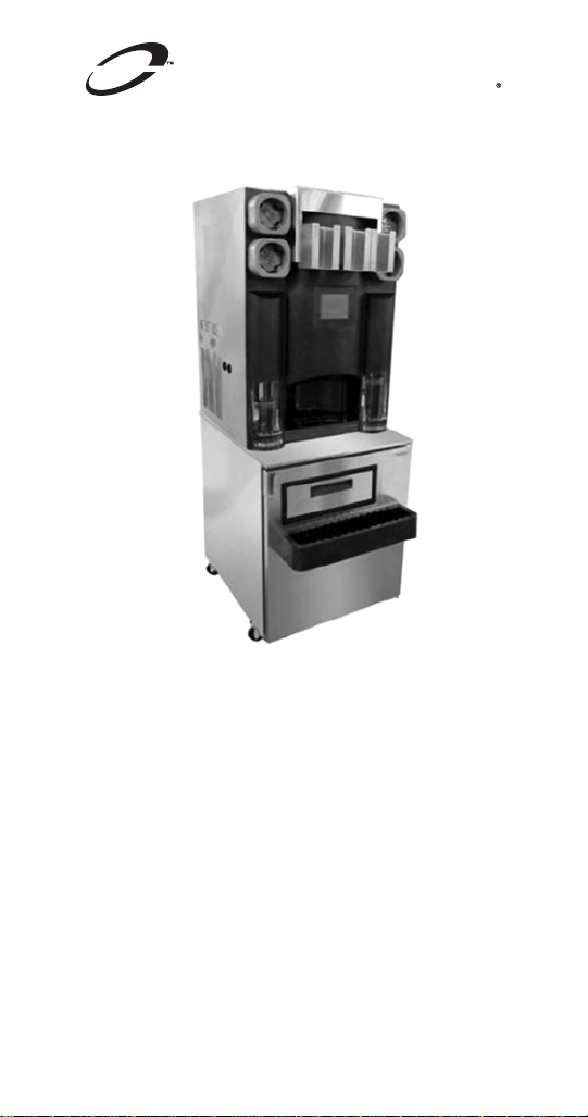
Multiplex
Blended
Beverage System
Technician’s
Handbook
This manual is updated as new information and models are released. Visit
our website for the latest manual. www.manitowocfsg.com
Leader in Ice & Beverage Dispensers
Part Number STH034 3/13
Page 2
Safety Notices
!
Warning
!
Caution
As you work on Manitowoc equipment, be sure to pay
close attention to the safety notices in this handbook.
Disregarding the notices may lead to serious injury
and/or damage to the equipment.
Throughout this handbook, you will see the following
types of safety notices:
Text in a Warning box alerts you to a potential
personal injury situation. Be sure to read the
Warning statement before proceeding, and work
carefully.
Text in a Caution box alerts you to a situation in
which you could damage the equipment. Be sure
to read the Caution statement before proceeding,
and work carefully.
Page 3

Procedural Notices
Important
As you work on Manitowoc equipment, be sure to read
the procedural notices in this handbook. These notices
supply helpful information which may assist you as
you work.
Throughout this handbook, you will see the following
types of procedural notices:
Text in an Important box provides you with
information that may help you perform a
procedure more efficiently. Disregarding this
information will not cause damage or injury, but it
may slow you down as you work.
NOTE: Text set off as a Note provides you with simple,
but useful, extra information about the procedure you
are performing.
Page 4
READ THESE BEFORE PROCEEDING:
!
Caution
Important
!
Warning
!
Warning
! Warning
Proper installation, care and maintenance are
essential for maximum performance and troublefree operation of your equipment. Visit our
website www.manitowocfsg.com for manual
updates, translations, or contact information for
service agents in your area.
Routine adjustments and maintenance
procedures outlined in this handbook are not
covered by the warranty.
Read this manual thoroughly before operating,
installing or performing maintenance on the
equipment. Failure to follow instructions in this
manual can cause property damage, injury or
death.
Do not use electrical appliances or accessories
other than those supplied by Manitowoc for your ice
machine model.
Two or more people or a lifting device are
required to lift this appliance.
Page 5
! Warning
This equipment contains high voltage electricity
! Warning
!
Warning
!
Warning
and refrigerant charge. Installation and repairs are
to be performed by properly trained technicians
aware of the dangers of dealing with high voltage
electricity and refrigerant under pressure.The
technician must also be certified in proper
refrigerant handling and servicing procedures. All
lockout and tag out procedures must be followed
when working on this equipment.
Do not damage the refrigeration circuit when
installing, maintaining or servicing the unit.
Do not operate equipment that has been misused,
abused, neglected, damaged, or altered/modified
from that of original manufactured specifications.
This appliance is not intended for use by persons
(including children) with reduced physical, sensory
or mental capabilities, or lack of experience and
knowledge, unless they have been given
supervision concerning use of the appliance by a
person responsible for their safety. Do not allow
children to play with this appliance.
All covers and access panels must be in place
and properly secured, before operating this
equipment.
Page 6

!
Warning
Do not obstruct machine vents or openings.
! Warning
! Warning
! Warning
Do not store gasoline or other flammable vapors
or liquids in the vicinity of this or any other
appliance.
Do not clean with water jet.
It is the responsibility of the equipment owner to
perform a Personal Protective Equipment Hazard
Assessment to ensure adequate protection
during maintenance procedures.
Page 7

! Warning
When using electric appliances, basic
precautions must always be followed, including
the following:
a. Read all the instructions before using
the appliance.
b. To reduce the risk of injury, close
supervision is necessary when an
appliance is used near children.
c. Do not contact moving parts.
d. Only use attachments recommended or
sold by the manufacturer.
e. Do not use outdoors.
f. For a cord-connected appliance, the
following must be included:
• Do not unplug by pulling on cord. To
unplug, grasp the plug, not the cord.
• Unplug from outlet when not in use
and before servicing or cleaning.
• Do not operate any appliance with a
damaged cord or plug, or after the
appliance malfunctions or is dropped
or damaged in any manner. Contact
the nearest authorized service facility
for examination, repair, or electrical
or mechanical adjustment.
g. Follow applicable lock out tag out
procedures before working on
equipment.
h. Connect to a properly grounded outlet
only.
Page 8

This Page Intentionally Left Blan k
Page 9

Table of Contents
Safety Notices . . . . . . . . . . . . . . . . . . . . . . 2
Procedural Notices . . . . . . . . . . . . . . . . . . 3
Read These Before Proceeding: . . . . . . . . .4
General Information
About Blend-In-Cup . . . . . . . . . . . . . . . . . 15
Serial Number Location . . . . . . . . . . . . . . 15
Specifications . . . . . . . . . . . . . . . . . . . . . . 16
Dimensions . . . . . . . . . . . . . . . . . . . . . . . . . 16
Product Delivery Location . . . . . . . . . . . . . .20
Electrical . . . . . . . . . . . . . . . . . . . . . . . . . . .22
Air / CO2, Plain & Chilled Water Inlets . . . . 25
System Pressures . . . . . . . . . . . . . . . . . . . .26
Drain Connections . . . . . . . . . . . . . . . . . . . .27
Installation
Step-by-Step Installation . . . . . . . . . . . . . 29
Pre-installation Checklist . . . . . . . . . . . . . . . 29
Connections . . . . . . . . . . . . . . . . . . . . . . . .31
Checklist . . . . . . . . . . . . . . . . . . . . . . . . . . .33
Cleaning & Start-up . . . . . . . . . . . . . . . . . . .34
Demonstrate . . . . . . . . . . . . . . . . . . . . . . . .36
Post Installation Checklist . . . . . . . . . . . . . .37
Component Identification
External . . . . . . . . . . . . . . . . . . . . . . . . . . .39
Left Side & Front . . . . . . . . . . . . . . . . . . . . .39
Front . . . . . . . . . . . . . . . . . . . . . . . . . . . . . . 39
Rear . . . . . . . . . . . . . . . . . . . . . . . . . . . . . . . 40
Internal . . . . . . . . . . . . . . . . . . . . . . . . . . . 41
Top Rear . . . . . . . . . . . . . . . . . . . . . . . . . . .41
Top Left . . . . . . . . . . . . . . . . . . . . . . . . . . . .43
Top Right . . . . . . . . . . . . . . . . . . . . . . . . . . .44
Bottom Cabinet . . . . . . . . . . . . . . . . . . . . . . 45
Maintenance
General Maintenance . . . . . . . . . . . . . . . . 47
Daily, Weekly Monthly . . . . . . . . . . . . . . . . . 47
Door Gasket Maintenance . . . . . . . . . . . . . . 49
Drain Maintenance - Inside Lower Cabinet .50
Refrigerators . . . . . . . . . . . . . . . . . . . . . . . . 50
Part Number STH034 3/13 9
Page 10

Stainless Steel Care & Cleaning . . . . . . . . .51
Doors/Hinges . . . . . . . . . . . . . . . . . . . . . . . . 52
Preventing Blower Coil Corrosion . . . . . . . .53
Cleaning Kits . . . . . . . . . . . . . . . . . . . . . . . .53
Daily Cleaning - Zone 1 . . . . . . . . . . . . . . 54
Gather the following supplies . . . . . . . . . . .55
Blenders / Dispense Area Cleaning & Sanitizing
56
Weekly Cleaning - Zone 2 . . . . . . . . . . . . 67
Gather the following supplies . . . . . . . . . . .68
Product Line Cleaning & Sanitizing . . . . . . .69
Sanitizing Ice Bin & Water Nozzles (Optional) 77
Blenders / Dispense Area Cleaning & Sanitizing
83
Drain Cleaning (Optional) . . . . . . . . . . . . . .94
Monthly Cleaning - Zone 3 . . . . . . . . . . . 100
Gather the following supplies . . . . . . . . . . .100
Ice Maker / Bin Descaling, Cleaning & Sanitizing
102
Other Monthly Tasks . . . . . . . . . . . . . . . . . .113
Biannual Descaling- Zone 3 . . . . . . . . . . 115
Turn ON Descaling . . . . . . . . . . . . . . . . . . .116
Gather the following supplies . . . . . . . . . . .121
Ice Maker / Bin Descaling, Cleaning & Sanitizing
122
Turn OFF Descaling . . . . . . . . . . . . . . . . . .133
Product Line Flush . . . . . . . . . . . . . . . . . 137
Gather The Following Supplies . . . . . . . . . .138
Manual Ice Machine Cleaning . . . . . . . . . 150
For MB-8-1PP . . . . . . . . . . . . . . . . . . . . . . .150
Bin / Dispenser Descale, Clean, & Sanitize .154
Bin / Dispenser Disassembly Descale, Clean, &
Sanitize . . . . . . . . . . . . . . . . . . . . . . . . . . . . 156
Annual Planned Maintenance . . . . . . . . . 159
Operation
Touch Screens . . . . . . . . . . . . . . . . . . . . . 161
Drink Selection Screen . . . . . . . . . . . . . . . .162
Flavor Selection Screen . . . . . . . . . . . . . . .163
Size Screen . . . . . . . . . . . . . . . . . . . . . . . . .164
Main Menu Screen . . . . . . . . . . . . . . . . . . .168
Manager’s Menu Screen . . . . . . . . . . . . . . .169
Product Inventory Screen . . . . . . . . . . . . . .200
Cleaning Screen . . . . . . . . . . . . . . . . . . . . .204
10 Part Number STH034 3/13
Page 11

Ice Making Sequence of Operation . . . . . 206
Ice Machines R290 Refrigerant . . . . . . . . . .206
Product Dispense Operation . . . . . . . . . . 207
Operation . . . . . . . . . . . . . . . . . . . . . . . . . . . 207
Refrigerated Cabinet Operation . . . . . . . 208
Normal Operation . . . . . . . . . . . . . . . . . . . .208
Evaporator & Condenser Fan Motor Operation
209
Operation in the Clean/Sanitize cycle . . . . .210
Adaptive Defrost . . . . . . . . . . . . . . . . . . . . .210
High Temp Alarm . . . . . . . . . . . . . . . . . . . .210
Thermistor Failure . . . . . . . . . . . . . . . . . . . .210
Other Operations . . . . . . . . . . . . . . . . . . . 211
Recommended Cups . . . . . . . . . . . . . . . . . . 211
Display Errors . . . . . . . . . . . . . . . . . . . . . . 213
Troubleshooting
Control System . . . . . . . . . . . . . . . . . . . . . 219
Will Not Run Diagnostics . . . . . . . . . . . . . . .219
Beverage System . . . . . . . . . . . . . . . . . . . 221
Beverage System Diagnostics . . . . . . . . . .221
Procedure to Clear Blocked Line . . . . . . . . . 222
Ice System . . . . . . . . . . . . . . . . . . . . . . . . . 224
Water System Checklist . . . . . . . . . . . . . . .225
ICE PRODUCTION & QUALITY CHECK . .226
MB-8-1PP Ice Machine Electrical Troubleshoot-
ing Flowchart . . . . . . . . . . . . . . . . . . . . . . . .228
Refrigerated Cabinet . . . . . . . . . . . . . . . . 235
Reach-in temperature Out of Range . . . . . .239
High Product Temperature . . . . . . . . . . . . . 243
Refrigeration System Diagnostics . . . . . 244
Analyzing Discharge Pressure or Temperature
244
Analyzing Suction Pressure or Temperature 246
Analyzing Discharge Pressure or Temperature
248
Analyzing Suction Pressure or Temperature 250
Procedure to Clear Blocked Line . . . . . . 252
How to Check Air/CO2 Pressure . . . . . . . 255
How to Adjust Air/CO2 Pressure . . . . . . . . . 259
How to Check Plain Water Pressure . . . . 263
Component Check Procedures
Control System . . . . . . . . . . . . . . . . . . . . . 265
Part Number STH034 3/13 11
Page 12

ON/OFF Rocker Switch . . . . . . . . . . . . . . . . 265
Power Relay . . . . . . . . . . . . . . . . . . . . . . . .267
Power Supply . . . . . . . . . . . . . . . . . . . . . . .269
UI (User Interface - Touchscreen) . . . . . . . . 271
SRB Board . . . . . . . . . . . . . . . . . . . . . . . . . .275
Blender Control Board . . . . . . . . . . . . . . . . .279
CIP (Clean In Place) Relay Board . . . . . . . .282
Beverage Components . . . . . . . . . . . . . . 284
Pressure Regulator - Water or CO2 . . . . . .284
Water Dispense Solenoid Valve . . . . . . . . .285
Syrup Solenoid Valve . . . . . . . . . . . . . . . . .286
Non Drip Valve . . . . . . . . . . . . . . . . . . . . . .287
Product Pump . . . . . . . . . . . . . . . . . . . . . . . 288
Step Motor . . . . . . . . . . . . . . . . . . . . . . . . . .289
Blender Motor . . . . . . . . . . . . . . . . . . . . . . .290
Home Position Switch . . . . . . . . . . . . . . . . .291
Door Switches . . . . . . . . . . . . . . . . . . . . . . .292
Water Rinse Solenoid Valve . . . . . . . . . . . . 293
Ice Machine Components . . . . . . . . . . . . 294
High Pressure Cutout (HPCO) Control . . . .294
Ice Maker Bin Level Relay . . . . . . . . . . . . . . 295
ICE CONDENSER COIL FAN . . . . . . . . . . .295
Infrared Ice Bin Control . . . . . . . . . . . . . . . .296
Refrigerated Cabinet . . . . . . . . . . . . . . . . 297
Temperature Thermistor - Nozzle, Cabinet or De-
frost . . . . . . . . . . . . . . . . . . . . . . . . . . . . . . .297
Evaporator Fan Motor . . . . . . . . . . . . . . . . .299
Duct Fan Motor . . . . . . . . . . . . . . . . . . . . . .300
Condenser Fan Motor . . . . . . . . . . . . . . . . .300
Compressor Electrical Diagnostics . . . . . . . 301
Compressor Drawing Locked Rotor . . . . . .302
Diagnosing Capacitors . . . . . . . . . . . . . . . .302
Filter-Driers . . . . . . . . . . . . . . . . . . . . . . . 303
Charts
Total System Refrigerant Charge . . . . . . 305
Operational Charts . . . . . . . . . . . . . . . . . 306
R290 Refrigerant - Ice Machine . . . . . . . . . .306
Diagrams
Wiring Diagrams . . . . . . . . . . . . . . . . . . . 307
R290 Ice Machine Refrigerant - Control System
Wiring Diagram . . . . . . . . . . . . . . . . . . . . . . 308
R290 Ice Machine Refrigerant - Refrigeration
Cabinet Wiring Diagram . . . . . . . . . . . . . . .309
12 Part Number STH034 3/13
Page 13

Models: MB-8-1PP . . . . . . . . . . . . . . . . . . .309
R290 Ice Machine Refrigerant - Ice Maker & Ice
Dispenser Wiring Diagram . . . . . . . . . . . . .310
Models: MB-8-1PP . . . . . . . . . . . . . . . . . . .310
R290 Ice Machine Refrigerant - Ice Maker Wiring
Diagram . . . . . . . . . . . . . . . . . . . . . . . . . . . .311
Models: MB-8-1PP . . . . . . . . . . . . . . . . . . .311
R290 Ice Machine Refrigerant - CIP BOard Wiring
Diagram . . . . . . . . . . . . . . . . . . . . . . . . . . . .312
Models: MB-8-1PP . . . . . . . . . . . . . . . . . . .312
. . . . . . . . . . . . . . . . . . . . . . . . . . . . . . . . . .313
. . . . . . . . . . . . . . . . . . . . . . . . . . . . . . . . . .314
Ice Machine Cleaning & Sanitizing Diagram 315
Models: MB-8-1PP . . . . . . . . . . . . . . . . . . .315
Ice Machine Cleaning & Sanitizing Diagram 316
Models: MB-8-1PP . . . . . . . . . . . . . . . . . . .316
Dispense System Diagram . . . . . . . . . . . . . 317
Part Number STH034 3/13 13
Page 14

14 Part Number STH034 3/13
Page 15
General Information
About Blend-In-Cup
The Blend-In-Cup beverage system is a self-contained
dispensing unit that allows the operator to make flavor
combinations of blended and non-blended drinks. It
holds product flavoring in a refrigerated reach-in base
enclosure, has a refrigerated ice making machine and
includes one or two mixing modules.
The operator controls and accesses the unit using a
lighted touch screen. Icons on the drink selection
screens represent the primary flavor combinations for
the drinks. There are multiple drink size options. Menu
changes and additions are uploaded using a USB
mass storage device and the Menu Connect Software
platform.
On-screen instructions also include operator
procedures for cleaning/sanitizing, checking inventory,
replacing product bags, selecting drink sizes and
manually preparing drinks. Managers and technicians
have access to menu/software updates, diagnostics
and other service screens.
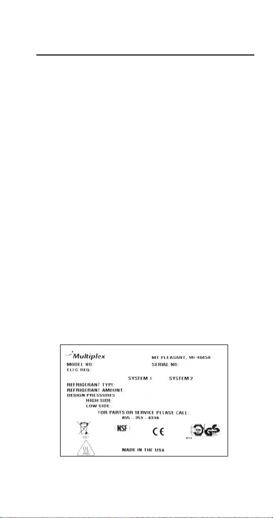
Serial Number Location
The Blend-In-Cup beverage system serial number is
listed on the serial number decal affixed to the middle
of the lower back panel. Another serial number decal
is located on the right side of the machine.
Sample Serial Tag
Part Number STH034 3/13 15
Page 16
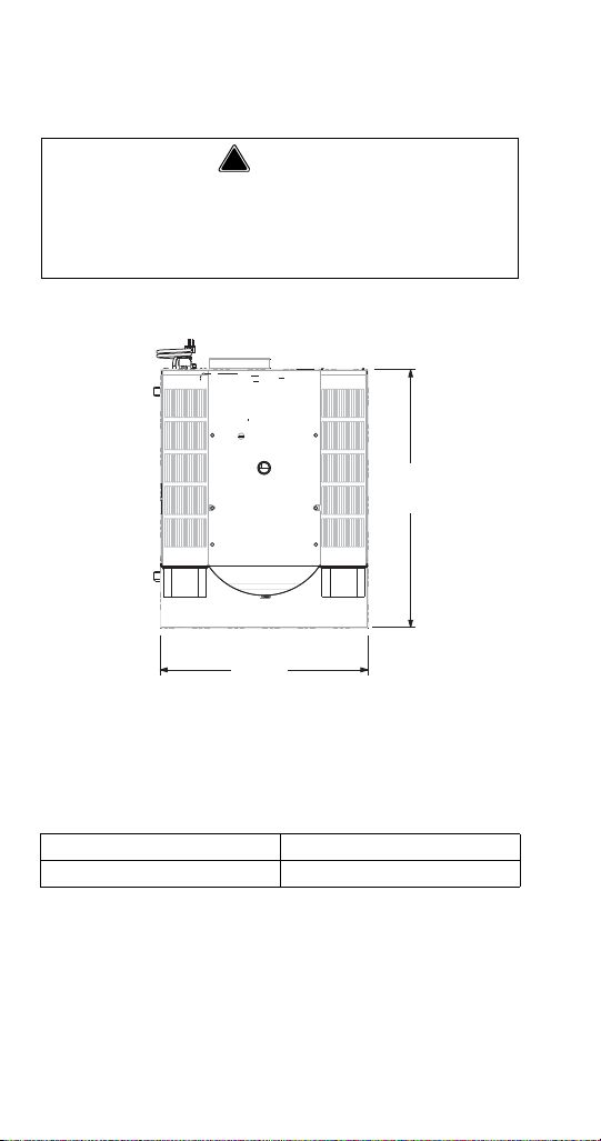
Specifications
! Warning
A
B
Elevation View
DIMENSIONS
To avoid instability the installation area must be
capable of supporting the weight of the equipment
and a full bin of ice. Additionally the equipment must
be level side to side and front to back.
A 26.00" (66 cm)
B 32.82" (83 cm)
16 Part Number STH034 3/13
Page 17
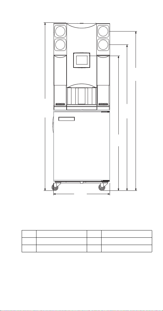
F
H
E
D
C
Elevation View
C 71.19" (181 cm) F 26.00" (66 cm)
D 65.19" (166 cm) H 75.07" (191 cm)
E 60.25" (153 cm)
Part Number STH034 3/13 17
Page 18
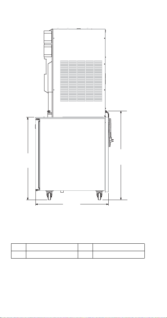
G 32.82" (83 cm) J 39.09" (99 cm)
G
I
J
Side View
I 36.15" (92 cm)
18 Part Number STH034 3/13
Page 19

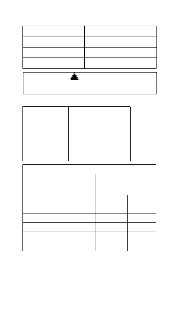
CAPACITY & WEIGHT
MB-8-1PP Ice Capacity H.P.
Refrigerant
Charge
Max
Product
Bin Load
Shipping
Weight
Empty
Weight
Full
Weight
Lower
Cabinet
–1/5
R-290
4.75 oz.
(134.7 g)
19.8 lbs.
(9 kg)
606 lbs
(275 kg)
Crated
492 lbs (
223 kg)
Unpacked
No Ice/
Product
656 lbs
(298 kg)
With Ice/
Product
Ice Maker
310 lbs.
(141 kg)/24 hr.
Bin Storage
30 lbs (14 kg)
1/2
R-290
3.17 oz
(90 g)
–
Part Number STH034 3/13 19
Page 20

PRODUCT DELIVERY LOCATION
!
Warning
The location selected for the Blend-In-Cup Beverage
System must meet the following criteria.
• The air temperature must be at least 40°F (4°C),
but must not exceed 90°F (32°C), climate class 4.
• The location must not be near heat-generating
equipment or in direct sunlight and must be
protected from weather.
• Plain or Chilled Inlet Water Temperature
min/max = 40°F / 90°F (4°C / 32°C).
• Always use the water supply line supplied when
installing this appliance. Never reuse an old supply
line.
• Verify floor of install location is within 1/2” of level
front to back, side to side.
• Keep equipment area clear of combustible
material.
Carbon Dioxide (CO2) displaces oxygen.
Exposure to a high concentration of CO
causes tremors, which are followed rapidly by
loss of consciousness and suffocation. If a CO
gas leak is suspected, particularly in a small
gas
2
2
area, immediately ventilate the area before
repairing the leak. CO2 lines and pumps must not
be installed in an enclosed space. An enclosed
space can be a cooler or small room or closet.
This may include convenience stores with glass
door self serve coolers. If you suspect CO
build up in an area, venting of the B-I-B pumps
and / or CO
monitors must be utilized.
2
may
2
20 Part Number STH034 3/13
Page 21
Clearances
! Warning
To p 18" (46 cm)
Sides 6" (15 cm)
Back 6" (15 cm)
Front 30" (76 cm)
Do not obstruct machine vents or openings.
Heat of Rejection
Model
All Single & Dual
Spindle Base
(Cabinet 1)
Ice Maker
(Cabinet 2)
Heat of Rejection
BTU/h
2100
5150
Operating Pressures PSIG
Air Temperature Entering
Condenser Coil
Freeze
Cycle
Discharge
Pressure
Suction
Pressure
70°F 150-170 17-23
90°F 180-200 18-24
110 °F 225-245 21-27
Part Number STH034 3/13 21
Page 22
ELECTRICAL
! Warning
!
Caution
All wiring must conform to local, state and national
codes.
Minimum Circuit Ampacity
The minimum circuit ampacity is used to help select
the wire size of the electrical supply. (Minimum circuit
ampacity is not the Blend-In-Cup Beverage System’s
running amp load.) The wire size (or gauge) is also
dependent upon location, materials used, length of
run, etc., so it must be determined by a qualified
electrician.
Electrical Requirements
Refer to Blend-In-Cup Beverage System Model/Serial
Plate for voltage/amperage specifications.
Operate equipment only on the type of electricity
indicated on the specification plate.
Voltage
The standard voltage is 230VAC-50Hz. A dedicated
electrical circuit is required, a power cord is provided
with all units.
Some models are available in different voltages and may
be equipped with a different plug, for details on each
model always refer to the serial number tag to verify
electrical data.
22 Part Number STH034 3/13
Page 23
Minimum Circuit Amperage Chart
Important
! Warning
! Warning
Due to continuous improvements, this
information is for reference only. Please refer to
the serial number tag to verify electrical data.
Serial tag information overrides information listed
on this page.
Model
Numbers
MB-8-1PP
Dual Spindle
Voltage/Cycle/
Refrigerant
230-240/50/1
R290
Total
Breaker Size
Amps
6.4 20A
(Max)
Grounding Instructions
The machine must be grounded in accordance
with national and local electrical codes.
This appliance must be grounded. In the event of
malfunction or breakdown, grounding provides a path
of least resistance for electric current to reduce the risk
of electric shock. This appliance is equipped with a
cord having an equipment-grounding conductor and a
grounding plug. The plug must be plugged into an
appropriate outlet that is properly installed and
grounded in accordance with all local codes and
ordinances.
Bonding Instructions (230-240V 50 Hz Models Only)
This appliance must be connected to the potential
equalization system in accordance with EN60335-1
and EN60335-2-75. A bonding lug is provided on the
lower right front corner of the appliance.
This machine must be connected to the potential
equalization system.
Part Number STH034 3/13 23
Page 24

!
Warning
When using electric appliances, basic
precautions must always be followed, including
the following:
a. Read all the instructions before using
the appliance.
b. To reduce the risk of injury, close
supervision is necessary when an
appliance is used near children.
c. Do not contact moving parts.
d. Only use attachments recommended or
sold by the manufacturer.
e. Do not use outdoors.
f. For a cord-connected appliance, the
following must be included:
• Do not unplug by pulling on cord. To
unplug, grasp the plug, not the cord.
• Unplug from outlet when not in use
and before servicing or cleaning.
• Do not operate any appliance with a
damaged cord or plug, or after the
appliance malfunctions or is dropped
or damaged in any manner. Contact
the nearest authorized service facility
for examination, repair, or electrical
or mechanical adjustment.
g. Follow applicable lock out tag out
procedures before working on
equipment.
h. Always unplug before replacing the lamp.
Replace the bulb with the same type.
i. Connect to a properly grounded outlet
only. See Grounding Instructions.
24 Part Number STH034 3/13
Page 25
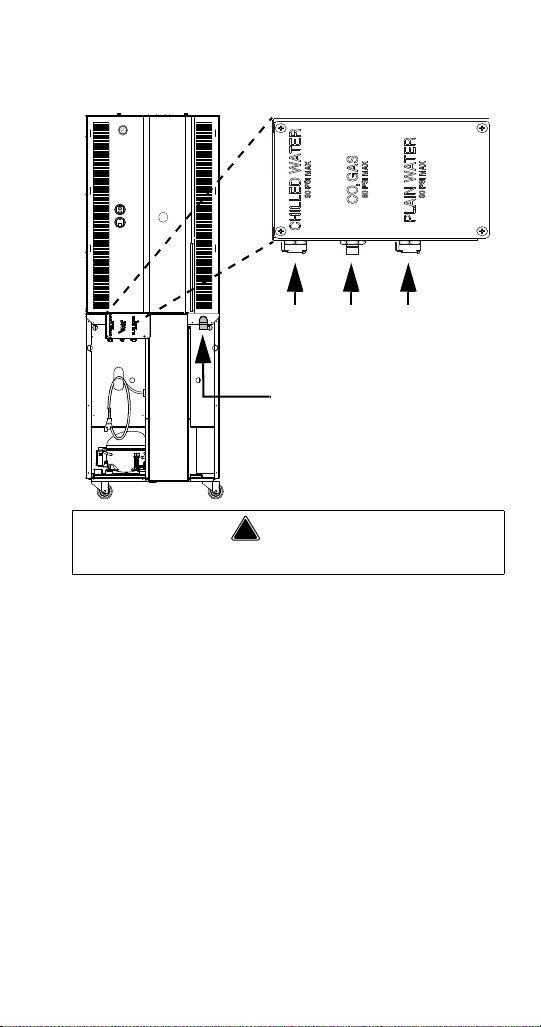
AIR / CO2, PLAIN & CHILLED WATER INLETS
!
Warning
Chilled
Wate r
IN
Air/
CO
2
IN
Plain
Water
IN
Drain
OUT
Connections in the Rear of the Unit
Connect to a potable water supply only.
• Use supplied 3/8” (.95 cm) panel-mounted hose
barb and 6' (1.8 m) of beverage tubing to connect
labeled coupling body fitting(s) on back of unit for
each supply connection.
• Do not connect either water connection to a hot
water supply. Be sure all hot water restrictors
installed for other equipment are working. (Check
valves on sink faucets, dishwashers, etc.)
• Install a water shut-off valve in the water line at the
rear of the machine.
• Insulate water inlet lines to prevent condensation.
Hard Water
In areas where the water is highly concentrated with
minerals the water should be tested by a water treatment
specialist, and the recommendations of the specialist
regarding filtration and/or treatment should be followed.
Part Number STH034 3/13 25
Page 26

SYSTEM PRESSURES
Important
Important
Important
Plain & Chilled Water
Requires the pressure measurement to be taken
only when rinse water is spraying (flowing
conditions) in a blender chamber.
• Plain Water Supply Pressure must be capable of
continuously suppling a minimum of 35 psi (241
kPa, 2.41 bar) during flowing conditions.
• If a separate chilled water source is used the
chilled supply pressure needs to be a minimum of
35 psi (241 kPa, 2.41 bar) at no flow conditions.
Water pressure affects the blender area cleaning,
a water booster may be required if pressure is
too low.
Air / CO
• Supply must be capable of 35 psi (241 kPa, 2.41
• Supply to the unit not to exceed 80 psi (345 / 552
26 Part Number STH034 3/13
2
Requires the pressure measurement to be taken
only when a product pump is being activated
(product pump during flow conditions).
bar) minimum during flowing conditions, measured
at the unit Air/CO
Air/CO2 Pressure on page 255.
kPa, 3.45 / 5.52 bar) maximum during no flow
conditions.
regulator. See How to Check
2
Page 27

DRAIN CONNECTIONS
• Connect supplied 1" ID hose to hose-barb
connection on machine.
• Drain lines must have a 1.5 inch drop per 5 feet of
run (2.5 cm per meter), and must not create traps.
• The floor drain must be large enough to
accommodate drainage from all drains.
• An air gap is included in the design of the machine
for backflow prevention, plumb to local code.
Part Number STH034 3/13 27
Page 28

28 Part Number STH034 3/13
This Page Intentionally Left Blan k
Page 29
Installation
Important
Step-by-Step Installation
These instructions are provided to assist the qualified
installer. Contact your Manitowoc Foodservice Service
Agent or call Manitowoc Foodservice for information
regarding start-up services.
Failure to follow these installation guidelines may
affect warranty coverage.
PRE-INSTALLATION CHECKLIST
Keep product bags in a cooler at least 24
hours prior to installation.
Any damage should be noted and reported
to the delivering carrier immediately.
Check the lower portion of the unit to be
sure casters are not bent.
Visually inspect the refrigeration package,
compressor compartment housing. Be sure
lines are secure and base is still intact.
Inspect installation location behind the BIC
for electrical outlet location, CO
hose fittings, and shutoff.
Check voltage at outlet dedicated for BIC.
Verify floor of install location is within 1/2” of
level front to back, side to side and all
casters are touching the floor.
Part Number STH034 3/13 29
, water
2
Page 30

! Warning
The mass of this appliance will allow it to move
uncontrolled on an inclined surface. Adequate
means must be provided to prevent uncontrolled
movement at all times.
Remove the side panels from the unit to
make the board connections, Air/CO
Water Regulator gauges accessible.
and
2
Check that board connections are secure
and did not vibrate loose during shipment.
Remove steel top panel. Check that the
black chute cover is sitting securely on the
chute. The ice maker will not operate
properly if it is out of place.
Check that both micro switches are in line
with the motor above the blenders.
30 Part Number STH034 3/13
Page 31

CONNECTIONS
Important
Chilled
Wate r
IN
Air/
CO
2
IN
Plain
Water
IN
Drain
OUT
Connections in the Rear of the Unit
Leave enough slack in the water/CO2/drain lines to
allow access to the rear of the machine without
disconnecting the lines.
Water
1. Connect the Plain and Chilled (if used) water lines
quick disconnect fittings and verify the water
regu lators are se t to 35 psi (241 kPa, 2.41 bar). The
Plain Water regulator is located on the left side of
the unit and the Chilled Water regulator is located
at the rear top. Final, during flow, settings will be
made once the unit is in operation.
See Cleaning
& Start-up on page 34 and/or “How to Check Air/
CO2 Pressure” on page 255.
Part Number STH034 3/13 31
Page 32

Air/CO2
Important
Important
2. Connect Air/CO2 line quick disconnect fitting.
Verify the Air/CO
unit is set to 35 PSI (241 kPa, 2.41 bar). Final
during flow settings will be made once the unit is
in operation.
Regulators are factory set but will need to be
checked and possibly adjusted under flowing
conditions once the unit is operational.
3. Confirm correct orientation of Water and Air/CO2
fittings.
4. Coil excess tubing and secure with tie straps.
Drain
5. Route drain line (minimum 1" ID) to drain,
maintain a 2" (51 mm) air gap. Cut to proper
length if needed (do not leave loops in drain). See
Drain Connections on page 27
Electrical
6. If all electrical and grounding requirements have
been followed (
page 22 & See Grounding Instructions on page
23) proceed to insert electrical plug from BIC into
wall receptacle.
7. Turn power and compressor switches, on the left
hand side of the unit and the rear, to the ON position.
8. The touch screen should energize and inform the
user to perform Zone 2 & 3 cleaning before the
unit can be put into operation.
2 regulator on the left side of the
See Electrical Requirements on
Do not add product to the machine until
cleaning and sanitizing are complete.
32 Part Number STH034 3/13
Page 33

CHECKLIST
Review before proceeding to Cleaning & Start-up.
Has all of the internal packing been
removed?
Have all of the electrical, water and CO2
connections been made?
Is there proper clearance around the
machine for air circulation?
Is the machine grounded / polarity correct?
Has the machine been installed where the
incoming water temperature will remain in
the range of 40°F / 90°F (4°C / 32°C)?
Have the regulators been set to 35 PSI (241
kPa, 2.41 bar)?
Have the blender door sensor position(s)
been checked?
Have the Compressor and Power switches
been turned to the ON position?
Part Number STH034 3/13 33
Page 34

CLEANING & START-UP
9. Clean and sanitize the Blend-In-Cup machine by
following the on screen instructions,
See Weekly
Cleaning - Zone 2 on page 67, “Monthly Cleaning Zone 3” on page 100, By doing so the following
will have been completed;
A. All beverage lines, ice maker, dispense area,
and blender chambers, cleaned and
sanitized.
B. Water run through the drain to verify it is
draining properly.
C. Product bags retrieved from walk-in cooler,
installed into the product bins and placed into
their proper location in the cabinet. See
Assigning Flavors on page 179 & “Procedure to
Install a Product Bag” on page 202.
D. All product lines primed and ready for use.
NOTE: During the cleaning process is an ideal time to
verify pressure regulator settings during flowing conditions.
E. Verify the Plain Water regulator is set correctly
during blend chamber cleaning, the regulator
should maintain 35 psi (241 kPa, 2.41 bar) under
flowing conditions.
F. Verify the Air/CO2 regulator is set correctly
during product line cleaning, the regulator should
maintain 35 psi (241 kPa, 2.41 bar) under flowing
conditions.
NOTE: The Chilled Water Regulator needs to be a
minimum of 35 psi (241 kPa, 2.41 bar) at no flow
conditions.
34 Part Number STH034 3/13
Page 35

Label
Important
10. Add labels to product bins, put labels in correct place.
11. Add labels anywhere else on the unit required.
Software
12. Verify correct firmware is loaded. See Firmware
Update Procedure on page 187.
13. Load recipes. See Recipe Loading Procedure on
page 190.
14. Verify correct drinks and flavors are available.
Calibrate
Allow cabinet to reach operating temperature
36°F/2°C – 38°F/3°C before calibrating.
Calibration will be inaccurate if performed
above operating temperatures.
15. Product calibration can be performed once
operating temperature has been reached.
Calibration Procedure on page 181 for step by
step calibration instructions. Once completed the
Blend-In-Cup machine is ready for use.
16. Reinstall top and side panels.
17. Push BIC into place.
18. Verify the unit is level and shim if necessary.
Part Number STH034 3/13 35
See
Page 36

DEMONSTRATE
19. Using the Interface. See Touch Screens on page 161
20. How to make drink. See Procedure to Make a
Drink on page 165.
21. Manager Menu options, using the default
password “A”. (The password can be changed.)
See Manager’s Menu Screen on page 169.
22. Set date and time to activate warranty. See Date
& Time Setting on page 173
23. Complete start-up form, sign, and have store
manager sign form. (Fax to number on form.)
36 Part Number STH034 3/13
Page 37

POST INSTALLATION CHECKLIST
Has the machine been properly sanitized?
Has each flavor been installed and primed?
Have the Air/CO2 and Plain water regulators
been correctly set during flowing conditions?
Is the machine cycling ON/OFF on the
temperature control?
Has the owner/operator been instructed
regarding maintenance procedures?
Has the owner/operator completed the
warranty registration card?
Part Number STH034 3/13 37
Page 38

38 Part Number STH034 3/13
This Page Intentionally Left Blan k
Page 39

Component Identification
Cup
Dispensers
Touch
Screen
Blending
Station
Doors
Product
Bins
Pull Out Tray
Plain Water
& CO2
Regulator
Gauges
USB Port
Power
Switch
Whip Cream
Door (Optional)
Cabinet Door
Product
Dispense
Area
Syrup Rail &
Dividers
(Optional)
Blending
Station
Doors
External
LEFT SIDE & FRONT
FRONT
Part Number STH034 3/13 39
Page 40

REAR
Compressor
Switch
Power
Switch
Chilled Water
Gauge
Water & Air/
CO2 Inlets
Drain
Power Cord
40 Part Number STH034 3/13
Page 41

Internal
1
2
8
3
4
7
5
6
TOP REAR
1. Chilled Water Regulator
2. Chilled Water Solenoid
3. Ice Maker Gear Box
4. Ice Maker Control
5. CIP Ice Maker Relay
6. Ice Maker Evaporator Fan
7. Ice Maker Compressor
8. Ice Maker Evaporator
Part Number STH034 3/13 41
Page 42

Ice Machine Control Box
SOFTWARE
LABEL
COMP.
DRIVE
L2
FAN
L2
EARTH
L2
L2
L1
L1
L2
60M
2ND
B-T
WTR
B-E
SWITCH
COMP.
COMM.
VAC
24
LINE
VAC
I.D.
DR
20M
C
POWER
RESET
I.D.
PROBE
WATER
Start Cap Start Relay Circuit
Control Board
Switch, on/off,
compressor
Board, stand off
control (4 required)
Gear Motor
Ice Making Unit
Compressor
Control Box
Condenser
Reservoir
Inlet Water Valve
Control Switch
Power Switch
Ice Machine Components
42 Part Number STH034 3/13
Page 43

TOP LEFT
1
3
2
4
5
7
9
6
8
10
11
13
12
18
19
16
14
15
17
1. CIP Board
2. SRB
3. 24 V Power Supply
4. 4 Amp Fuse Power Supply
5. 4 Amp Fuse CIP System
6. Blender Home Position Micro Switch
7. Blender Board
8. Blender Motor
9. Linear Slide Motor
10. ON/OFF Switch
11. USB Port
12. Power Relay
13. Blender Door Relay
14. Blender 1 Rinse Nozzle Solenoid
15. Water Dispense Solenoid
16. Double Water inlet solenoid
17. EMC Filter
18. Air/C02 Regulator
19. Water Regulator
Part Number STH034 3/13 43
Page 44

T OP RIGHT
1
3
9
11
10
12
5
8
4
2
7
6
1. CIP Pump
2. Dump valve
3. Blender Motor
4. Blender Home Position Micro Switch
5. Mixer Board
6. CIP Ice bin solenoid
7. CIP C02/Air solenoid
8. Ice Maker Bin Relay
9. CIP Ice maker solenoid
10. Linear Slide Motor
11. Blender Door Relay
12. Blender 2 rinse nozzle solenoid
44 Part Number STH034 3/13
Page 45

BOTTOM CABINET
4
4
2
2
2
1
3
Pumps & Solenoids
1. None Drip Valves (x8)
2. Product Pumps (x8)
3. Product Bag Nozzles (x8)
4. Solenoid Valves (x2)
Part Number STH034 3/13 45
Page 46

Pump & Solenoid Numbering
1 2 3 4 5 6 7 8
Product
Pumps
Product
Pumps
Expansion Valves
Air/CO2 Solenoids
These numbers correspond to the product bins and inventory
numbers in the User Interface.
4
3
3
2
1
1
1
256
Refrigeration
1. Duct Fan
2. Evaporator Coil
3. Evaporator Fans (2)
4. Cabinet Sensor
3
1256
4
3478
7
8
46 Part Number STH034 3/13
Page 47

Maintenance
General Maintenance
This section covers common unit components and
their care. The chart below is an overview of the
maintenance that the end user and service technician
should perform, and the frequency. These figures are
the minimum required. If the Ice Machine is supplied
with hard water, more frequent cleaning should be
performed. If the condenser air filter is totally blocked,
after one week, more frequent cleaning is
recommended. (X = End User, S = Service Company
DAILY, WEEKLY MONTHLY
Maintenance Daily Weekly Monthly
Blender / Dispense Area
Cleaning/ Sanitizing
(Zone 1 Cleaning)
Product Line Cleaning &
Sanitizing
(Zone 2 Cleaning)
Drain Cleaning X
Clean Air Filters X
Clean/Sanitize
Ice Maker/Bin
(Zone 3 Cleaning)
Descale
Ice Maker/Bin
(Zone 3 Cleaning)
Clean Condenser Coil
Inspect Ice Maker /
Dispenser Parts
Check Ice Quality X X
X
X
X
Part Number STH034 3/13 47
Page 48

QUARTERLY & BIANNUAL
Maintenance 3 Months 6 Months
Blender / Dispense Area
Cleaning/ Sanitizing
(Zone 1 Cleaning)
Product Line Cleaning &
Sanitizing
(Zone 2 Cleaning)
Drain Cleaning
Clean Air Filters
Clean/Sanitize
Ice Maker/Bin
(Zone 3 Cleaning)
Descale
Ice Maker/Bin
(Zone 3 Cleaning)
Clean Condenser Coil X
Inspect Ice Maker /
Dispenser Parts
Check Ice Quality
ANNUAL, SHUTDOWN & START-UP
After
Maintenance Annual
Blender / Dispense Area
Cleaning/ Sanitizing
(Zone 1 Cleaning)
Product Line Cleaning &
Sanitizing
(Zone 2 Cleaning)
Drain Cleaning X
Clean Air Filters X
Clean/Sanitize
Ice Maker/Bin
(Zone 3 Cleaning)
Descale
Ice Maker/Bin
(Zone 3 Cleaning)
Clean Condenser Coil X
Inspect Ice Maker /
Dispenser Parts
Check Ice Quality S S S
S S S
Prolonged
Shutdown
X S
X S
S
S
At Start-
up
48 Part Number STH034 3/13
Page 49

!
Warning
Disconnect power to the unit before performing
Important
any service or maintenance functions.
If the machine going to be shutdown for any
length of time it is recommended to go through
the Zone 2 - Weekly Cleaning both prior to
turning off the unit and when returned to use.
If the unit is turned off the product will no longer
be kept cool in the refrigeration cabinet, remove
all product bags and keep refrigerated to prevent
spoilage.
DOOR GASKET MAINTENANCE
Door gaskets require regular cleaning to prevent mold and
mildew buildup and also to retain the elasticity of the
gasket. Gasket cleaning can be done with the use of warm
soapy water. Avoid full strength cleaning products on
gaskets as this can cause them to become brittle and
crack. Never use sharp tools or knives to scrape or clean
the gasket. Gaskets can be easily replaced and do not
require the use of tools or an authorized service person.
The gaskets are “Dart” style and can be pulled out of the
groove in the door and new gaskets can be “pressed”
back into place.
Part Number STH034 3/13 49
Page 50

DRAIN MAINTENANCE - INSIDE LOWER CABINET
!
Warning
Each unit has a drain located inside the unit that removes
the condensation from the evaporator coil and routes it to
an external condensate evaporator pan. Each drain can
become loose or disconnected during normal use. If you
notice water accumulation on the inside of the unit, be sure
the drain tube is connected to the evaporator drain pan. If
water is collecting underneath the unit, make sure the end
of the drain tube is in the condensate evaporator in the
machine compartment. The leveling of the unit is important
as the units are designed to drain properly when level. Be
sure all drain lines are free of obstructions.
REFRIGERATORS
Do not damage the refrigeration circuit when
installing, maintaining or servicing the unit.
The interior and exterior can be cleaned using soap
and warm water. If this isn’t sufficient, try ammonia and
water or a nonabrasive liquid cleaner. When cleaning
the exterior, always rub with the “grain” of the stainless
steel to avoid marring the finish. Do not use an
abrasive cleaner because it will scratch the stainless
steel and can damage the breaker strips and gaskets.
50 Part Number STH034 3/13
Page 51

STAINLESS STEEL CARE & CLEANING
Important
To prevent discoloration or rust on stainless steel,
several important steps need to be taken. First, we
need to understand the properties of stainless steel.
Stainless steel contains 70-80% iron, which will rust. It
also contains 12-30% chromium, which forms an
invisible passive film over the steel’s surface, which
acts as a shield against corrosion. As long as the
protective layer is intact, the metal is still stainless. If
the film is broken or contaminated, outside elements
can begin to break down the steel and begin to form
discoloration or rust. Proper cleaning of stainless steel
requires soft cloths or plastic scouring pads.
Never Use Steel Pads, W ire Brushes or Scrapers!
Cleaning solutions need to be alkaline based or nonchloride cleaners. Any cleaner containing chlorides will
damage the protective film of the stainless steel.
Chlorides are also commonly found in hard water,
salts, and household and industrial cleaners. If
cleaners containing chlorides are used, be sure to
rinse repeatedly and dry thoroughly. Routine cleaning
of stainless steel can be done with soap and water.
Extreme stains or grease should be cleaned with a
non-abrasive cleaner and plastic scrub pad. Always
rub with the grain of the steel. There are stainless steel
cleaners available which can restore and preserve the
finish of the steel’s protective layer. Early signs of
stainless steel breakdown are small pits and cracks. If
this has begun, clean thoroughly and start to apply
Part Number STH034 3/13 51
Page 52

stainless steel cleaners in attempt to restore the
!
Caution
!
Caution
passivity of the steel.
Never use an acid based cleaning solution! Many
food products have an acidic content, which can
deteriorate the finish. Be sure to clean the
stainless steel surfaces of ALL food products.
Common items include: tomatoes, peppers and
other vegetables.
Never use a high-pressure water wash for this
cleaning procedure as water can damage the
electrical components located near or at the
condenser coil.
DOORS/HINGES
Over time and with heavy use doors and hinges may
become loose. If this happens tighten the screws that
mount the hinge brackets to the frame of the unit. Loose or
sagging doors can cause the hinges to pull out of the
frame, which may damage both the doors and the hinges.
In some cases this may require trained & qualified service
agents or maintenance personnel to perform repairs.
NOTE: Do not place hot pans on/against the blue ABS
liner. Do not throw items into the storage area. Failure to
follow these recommendations could result in damage to
the interior of the cabinet or to the blower coil. Overloading
the storage area, restricting the airflow, and continuous
opening and closing of the doors and drawers will hamper
the unit’s ability to maintain operational temperature.
52 Part Number STH034 3/13
Page 53

PREVENTING BLOWER COIL CORROSION
Immediately wipe up all spills.
CLEANING KITS
Complete cleaning kits are available for single spindle (part
number 000-BIC-001R) and dual spindle (part number 000BIC-001Q) units. These kits include the following;
• (3) three 5 gallon buckets
• Bucket labels for Wash, Rinse, & Sanitizing
• Red & Blue cups for blender cleaning
• Squeeze Bottle
• Dispense Area Shield
• Tubing Manifold for product line cleaning
Part Number STH034 3/13 53
Page 54

Daily Cleaning - Zone 1
Main Menu Touch Screen
Cleaning Touch Screen
NOTE: The following procedures are the basic daily
cleaning instructions, on screen instructions can vary
depending on the recipe that was created with the
MenuConnect program. * These items are optional
and may not be displayed on all EasyTouch screens
during ZONE 1 Cleaning.
• Time to complete - 15 minutes
1. Cycle touch screen to the Main Menu and select
the Cleaning Icon.
2. In the cleaning screen select the Zone 1 Icon.
54 Part Number STH034 3/13
Page 55

GATHER THE FOLLOWING SUPPLIES
Follow the on screen instructions and gather the
following supplies;
Clean towels (* Cloths)
Spray Cleaner & Detergent
Solution
(Approved dish detergent solution)
Spray Sanitizer & Solution
(Approved sanitizer solution that
provides 100 ppm available chlorine.)
Red & Blue Cleaning Cups
(1 of each per blender station)
RB
* Scoop, Cleaning Brush, Gloves
& Safety Glasses
* These items are optional and may not be displayed on all
EasyTouch screens.
NOTE: If other cleaners are used, it is possible they will
not clean or sanitize your machine to NSF standards.
• Press the down arrow to continue
Part Number STH034 3/13 55
Page 56

BLENDERS / DISPENSE AREA CLEANING & SANITIZING
Blend Chamber Grate Removal
Grate Removal / Blender Station Wash
1. Follow the on screen instructions;
• * Put on gloves & safety glasses.
2. Remove grate from the mixer station(s)
• Press the down arrow to continue
3. Spray all surfaces inside blender station with
cleaning solution.
• * Then scrub thoroughly with approved
cleaning brush.
4. Thoroughly wipe down all surfaces of mixer
station & repeat for the other side if applicable.
• Press the down arrow to continue.
56 Part Number STH034 3/13
Page 57

Dispensing Area Cleaning
Dispense Area Screen
1. Remove center grate from dispensing area.
2. Spray all dispensing area surfaces with cleaning solution.
• * Then use approved cleaning brush to
thoroughly scrub area.
• Press the down arrow to continue.
3. Thoroughly spray each individual dispense nozzle
with cleaning solution and apply cleaner to each
individual dispensing valve.
• * Then use approved cleaning brush to
carefully scrub area.
4. Thoroughly wipe all dispense valves and
dispense area with a clean towel.
• Press the down arrow to continue.
Part Number STH034 3/13 57
Page 58

Mixer Door Removal
Mixer Door Removal Screen
1. Slightly open mixer door.
2. Squeeze at bottom of door.
3. Tilt out and pull the door down and out.
4. Repeat for other door if applicable.
• Press the down arrow to continue.
58 Part Number STH034 3/13
Page 59

Blender Station Wash
Blender Station Wash Screen
1. Completely spray blender station with cleaning solution.
• * Use cleaning brush to thoroughly scrub
down the entire area.
• * Using the approved cleaning brush,
thoroughly scrub down top of blender cap and
blender arm
2. Lift blender cap and thoroughly wipe down top of
blade housing and bottom of blender cap.
• * Scrub (with the approved cleaning brush) top of
blade housing and bottom of blender cap.
• Press the down arrow to continue.
3. Thoroughly spray with sanitizer solution.
• * Using the approved cleaning brush to scrub
entire blender assembly.
4. Repeat for other side if applicable.
• Press the down arrow to continue.
Part Number STH034 3/13 59
Page 60

Reinstall Grate(s)/Door(s)
Important
Grates & Doors Screen
1. Take all grate(s) and door(s) to sink to wash and
sanitize.
Never Use Steel Pads, Wire Brushes, Scrapers,
or any Abrasive Cleaners / Scouring Pads!
2. Do not put in dishwasher or power soaker.
3. Reinstall mixer grate(s).
4. Reinstall dispensing area grate.
5. Reinstall mixer door(s)
• Press the down arrow to continue.
60 Part Number STH034 3/13
Page 61

Blender Wash
Blender Wash Screen
Washing Screen
1. Place blue cleaning cup(s) with wash solution in
blender station(s) and close the blender doors.
• Use approved dish detergent solution)
2. Press the green check to begin.
The blenders will lower into the wash solution and spin
to clean. WASHING will display on the screen.
Part Number STH034 3/13 61
Page 62

Follow the on screen instruction, when prompted remove
Remove Cup Screen
Rinse Cup Screen
the blue cup(s) and pour wash solution down the drain.
Close the blender door(s) and RINSING will display on
the screen while the machine rinses the blenders.
Finished will display on the screen then progress to
the Blender Sanitizing screen.
62 Part Number STH034 3/13
Page 63

Blender Sanitizing
Blender Sanitizing Screen
Washing Screen
1. Place red sanitizing cup(s) with sanitizing solution
in blender station(s) and close the blender doors.
• Use approved sanitizer solution that provides
100 ppm available chlorine.
2. Press the green check to begin.
The blenders will lower into the wash solution and spin
to sanitize. SANITIZE will display on the screen.
Part Number STH034 3/13 63
Page 64

Follow the on screen instruction, when prompted
Remove Cup Screen
Rinse Cup Screen
remove the red cup(s) and pour sanitizing solution
down the drain.
Close the blender door(s) and RINSING will display on
the screen while the machine rinses the blenders.
Finished will display on the screen then progress to
the Blender Station Sanitizing screen.
64 Part Number STH034 3/13
Page 65

Blender Station Sanitizing
Blender Station Sanitizing Screen
1. Completely spray blender station with cleaning
solution.
• * Use cleaning brush to thoroughly scrub
down the entire area.
2. Allow to air dry, Do not wipe off sanitizer!
3. Repeat for other side if applicable.
• Press the down arrow to continue.
Part Number STH034 3/13 65
Page 66

Dispensing Area Sanitizing
Dispense Area Sanitizing Screen
1. Thoroughly spray each individual dispense nozzle
with sanitizer solution.
2. Thoroughly spray dispense area with sanitizer solution.
3. Allow to air dry, Do not wipe off sanitizer!
• * Remove gloves & safety glasses
• Press the green check to signify you have
completed the Zone 1 Daily Cleaning.
66 Part Number STH034 3/13
Page 67

Weekly Cleaning - Zone 2
Main Menu Touch Screen
Cleaning Touch Screen
NOTE: The following procedures are the basic weekly
cleaning instructions, on screen instructions can vary
depending on the recipe that was created with the
MenuConnect program or options chosen in the
Managers Menu. * These items are optional and may
not be displayed on all EasyTouch screens during
ZONE 2 Cleaning.
• Time to complete - 1 hour
1. Cycle touch screen to the Main Menu and select
the Cleaning Icon.
2. In the cleaning screen select the Zone 2 Icon.
Part Number STH034 3/13 67
Page 68

NOTE: Failure to complete the weekly cleaning
RB
123
sequence entirely will not reset the weekly cleaning
timer and will require the process to be repeated.
GATHER THE FOLLOWING SUPPLIES
Follow the on screen instructions and gather the
following supplies;
Clean towels (* Cloths)
Spray Cleaner & Detergent
Solution
(Approved dish detergent solution)
Spray Sanitizer & Solution
(Approved sanitizer solution that
provides 100 ppm available
chlorine.)
Red & Blue Cleaning Cups
(1 of each per blender station)
Set of Three (3) Cleaning Buckets
(Wash, Rinse & Sanitize Solutions)
Splash Shield
Cleaning Manifold
* Drain cleaner & Dispenser
* Scoop, Cleaning Brush,
Gloves & Safety Glasses
* These items are optional and may not be displayed on all
EasyTouch screens.
68 Part Number STH034 3/13
Page 69

NOTE: If other cleaners are used, it is possible they will
Prepare Solutions Screen
not clean or sanitize your machine to NSF standards.
• Press the down arrow to continue
PRODUCT LINE CLEANING & SANITIZING
Prepare Cleaning Solutions
1. Follow the on screen instructions;
• * Put on gloves & safety glasses.
2. Fill wash bucket with water and add detergent.
(Approved dish detergent solution.)
3. Fill rinse bucket with water.
4. Fill sanitizer bucket with water and add approved sanitizer.
(Approved sanitizer solution that provides 100 ppm
available chlorine.)
5. Fill blue cleaning cup(s) with wash solution and set aside.
(Approved dish detergent solution.)
• Press the down arrow to continue.
6. Fill red sanitizing cup(s) with sanitizing solution and
set aside. (Approved sanitizer solution that provides
100 ppm available chlorine.)
• Press the down arrow to continue.
Part Number STH034 3/13 69
Page 70

Washing Instructions
Washing Instructions Screen
1. Remove grate from center dispensing area.
2. Install splash guard in dispense area.
3. Remove product holders from cabinet.
4. Take product holders to refrigerated storage.
• Press the down arrow to continue
5. Spray and wipe each bib connector and area with
cleaner.
6. Spray each bib connector and area with sanitizer.
7. Connect a cleaning hose to each product nozzle.
• Press the down arrow to continue
8. Place cleaning manifold in wash bucket.
9. Press the green check to begin cleaning the lines.
70 Part Number STH034 3/13
Page 71

This will automatically send the wash solution through
Product Line Washing Screen
each line (slot), displaying the progress on the screen,
30 seconds per slot.
When washing has completed the Rinsing Instructions
Screen will appear automatically.
Part Number STH034 3/13 71
Page 72

Rinsing Instructions
Rinsing Instructions Screen
Product Line Rinsing Screen
1. Remove cleaning manifold from wash bucket.
2. Place cleaning manifold in rinse bucket.
3. Press the green check begin rinsing the lines.
This will automatically send the rinse solution through
each line (slot), displaying the progress on the screen,
30 seconds per slot.
When rinsing has completed the Sanitization
Instructions Screen will appear automatically.
72 Part Number STH034 3/13
Page 73

Sanitization Instructions
Sanitizing Instructions Screen
Product Line Sanitizing Screen
1. Remove cleaning manifold from rinse bucket.
2. Place cleaning manifold in sanitize bucket begin
sanitizing the lines.
3. Press the green check begin sanitizing the lines.
This will automatically send the sanitizing solution
through each line (slot), displaying the progress on the
screen, 30 seconds per slot.
When sanitizing has completed the Purging
Instructions Screen will appear automatically.
Part Number STH034 3/13 73
Page 74

Purging Instructions
Sanitizing Instructions Screen
Product Line Purging Screen
1. Disconnect the cleaning hoses from the product nozzles.
2. Press the green check begin purging the lines.
Air is pushed through each line (slot) blowing out any
remaining liquid, displaying the progress on the
screen, 30 seconds per slot.
When purging has completed the Reinstall Inventory
Screen will appear automatically.
74 Part Number STH034 3/13
Page 75

Reinstall Inventory
Reinstall Inventory Screen
Product Line Purging Screen
1. Retrieve product holders from refrigerated storage.
2. Reinstall each product holder into correct slot.
3. Remove splash guard from dispense area.
4. Reinstall center grate under dispensing area.
• Press the down arrow to continue.
5. Place a large cup under dispensing nozzles
6. Press the green check to prime each line.
This will automatically prime each line with product.
The screen will read Priming Slot X. Each slot will
change from Purged to Clean.
When priming has completed the Prime Completion
Screen will appear automatically.
Part Number STH034 3/13 75
Page 76

Auto Prime Complete
Prime Completed Screen
1. Remove and dispose of large cup with primed product.
2. Press the green check to continue to the
Sanitizing Ice Bin & Water Nozzles screen, if this
feature is not turned on in the Managers Menu
proceed to
“Blenders / Dispense Area Cleaning &
Sanitizing” on page 83.
76 Part Number STH034 3/13
Page 77

SANITIZING ICE BIN & WATER NOZZLES (OPTIONAL)
123
* These steps will only display during the ZONE 2
Cleaning on units with this feature turned on in the
Managers Menu. If this feature is not active the
interface will automatically proceed to
“Blenders /
Dispense Area Cleaning & Sanitizing” on page 83.
Gather the Following Supplies
Cleaning Buckets - Set of
Three (3)
Cleaning Hose *
(Located below product bins)
Ice Removal Chute
Splash Guard
Sanitizing Solution
(Approved sanitizer solution that
provides 100 ppm available
chlorine.)
* Scoop, Cleaning Brush,
Gloves & Safety Glasses
* These items are optional and may not be displayed on
all EasyTouch screens.
NOTE: If other cleaners are used, it is possible they
will not clean or sanitize your machine to NSF
standards.
• Press the down arrow to continue
Part Number STH034 3/13 77
Page 78

Removal of Ice
Ice Removal Screen
Ice Dispense Timer Screen
Follow the on screen instructions;
1. Install ice removal chute in dispenser area.
2. Place empty bucket on floor under ice chute.
3. Press the green check to begin dispensing ice.
• The Ice Dispensing Timer Screen will display,
the machine will empty of ice.
78 Part Number STH034 3/13
Page 79

Ice Disposal
Ice Disposal Screen
1. Dispose of ice in the bucket and set aside.
2. Remove ice removal chute from the dispenser
area and set aside.
3. Press the green check.
Part Number STH034 3/13 79
Page 80

Sanitizing Ice Bin & Water Nozzles Prep
Bin & Nozzles Prep Screen
Sanitizing Timer Screen
1. Install splash guard in dispense area.
• * Put on gloves and safety glasses.
2. Fill sanitizer bucket with water and add sanitizer.
(Use approved sanitizer solution that provides
100 ppm available chlorine.)
3. Place cleaning hose into the sanitizer bucket.
4. Press the green check to begin sanitizing the ice
bin and water nozzles.
• The Sanitizing Timer Screen will display, and
count down during the sanitizing process.
80 Part Number STH034 3/13
Page 81

Discard Sanitizer
Discard Sanitizer Screen
1. Install cleaning hose into the bottom of the
refrigerated cabinet.
2. Discard remaining sanitizer from the bucket.
3. Press green check to continue.
Part Number STH034 3/13 81
Page 82

Rinsing Sanitizer Prep
Plain Water Rinse
Rinse Timer Screen
1. Install splash guard in the dispense area.
2. Press the green check to begin the plain water
rinse cycle.
• The Rinse Timer Screen will display, and
count down during the rinsing process then
automatically proceed to the Grate Removal/
Blender Station Wash Screen.
82 Part Number STH034 3/13
Page 83

BLENDERS / DISPENSE AREA CLEANING & SANITIZING
Blend Chamber Grate Removal
Grate Removal / Blender Station Wash
1. Remove grate from the mixer station(s)
2. Spray all surfaces inside blender station with
cleaning solution.
• * Then scrub thoroughly with approved
cleaning brush.
• Press the down arrow to continue.
3. Thoroughly wipe down all surfaces of mixer
station & repeat for the other side if applicable.
• Press the down arrow to continue.
Part Number STH034 3/13 83
Page 84

Dispensing Area Cleaning
Dispense Area Screen
1. Remove center grate from dispensing area.
2. Spray all dispensing area surfaces with cleaning
solution.
• * Then use approved cleaning brush to
thoroughly scrub area.
• Press the down arrow to continue.
3. Thoroughly spray each individual dispense nozzle
with cleaning solution and apply cleaner to each
individual dispensing valve.
• * Then use approved cleaning brush to
carefully scrub area.
4. Thoroughly wipe all dispense valves and
dispense area with a clean towel.
• Press the down arrow to continue.
84 Part Number STH034 3/13
Page 85

Mixer Door Removal
Mixer Door Removal Screen
1. Slightly open mixer door.
2. Squeeze at bottom of door.
3. Tilt out and pull the door down and out.
4. Repeat for other door if applicable.
• Press the down arrow to continue.
Part Number STH034 3/13 85
Page 86

Blender Station Wash
Blender Station Wash Screen
1. Completely spray blender station with cleaning solution.
• * Use cleaning brush to thoroughly scrub
down the entire area.
• * Using the approved cleaning brush,
thoroughly scrub down top of blender cap and
blender arm.
2. Lift blender cap and thoroughly wipe down top of
blade housing and bottom of blender cap.
• * Scrub (with the approved cleaning brush) top of
blade housing and bottom of blender cap.
• Press the down arrow to continue.
3. Thoroughly spray with sanitizer solution.
• * Using the approved cleaning brush to scrub
entire blender assembly.
4. Repeat for other side if applicable.
• Press the down arrow to continue.
86 Part Number STH034 3/13
Page 87

Reinstall Grate(s)/Door(s)
Important
Grates & Doors Screen
1. Take all grate(s) and door(s) to sink to wash and
sanitize.
Never Use Steel Pads, Wire Brushes, Scrapers,
or any Abrasive Cleaners / Scouring Pads!
2. Do not put in dishwasher or power soaker.
3. Reinstall mixer grate(s).
4. Reinstall dispensing area grate.
5. Reinstall mixer door(s).
• Press the down arrow to continue.
Part Number STH034 3/13 87
Page 88

Blender Wash
Blender Wash Screen
Washing Screen
1. Place blue cleaning cup(s) with wash solution in
blender station(s) and close the blender doors.
• 0.425 oz/5 gal or Approved dish detergent
solution)
2. Press the green check to begin.
The blenders will lower into the wash solution and spin
to clean. WASHING will display on the screen.
88 Part Number STH034 3/13
Page 89

Follow the on screen instruction, when prompted
Remove Cup Screen
Rinse Screen
remove the blue cup(s) and pour wash solution down
the drain.
Close the blender door(s) and RINSING will display on
the screen while the machine rinses the blenders.
Finished will display on the screen then progress to
the Blender Sanitizing screen.
Part Number STH034 3/13 89
Page 90

Blender Sanitizing
Blender Sanitizing Screen
Sanitizing Screen
1. Place red sanitizing cup(s) with sanitizing solution
in blender station(s) and close the blender doors.
• Use approved sanitizer solution that provides
100 ppm available chlorine.
2. Press the green check to begin.
The blenders will lower into the wash solution and spin
to sanitize. SANITIZE will display on the screen.
90 Part Number STH034 3/13
Page 91

Follow the on screen instruction, when prompted
Remove Cup Screen
Rinse Screen
remove the red cup(s) and pour sanitizing solution
down the drain.
Close the blender door(s) and RINSING will display on
the screen while the machine rinses the blenders.
Finished will display on the screen then progress to
the Blender Station Sanitizing screen.
Part Number STH034 3/13 91
Page 92

Blender Station Sanitizing
Blender Station Sanitizing Screen
1. Completely spray blender station with cleaning solution.
• * Use cleaning brush to thoroughly scrub
down the entire area.
2. Allow to air dry, Do not wipe off sanitizer!
3. Repeat for other side if applicable.
• Press the down arrow to continue.
92 Part Number STH034 3/13
Page 93

Dispensing Area Sanitizing
Dispense Area Sanitizing Screen
1. Thoroughly spray each individual dispense nozzle
with sanitizer solution.
2. Thoroughly spray dispense area with sanitizer
solution.
3. Allow to air dry, Do not wipe off sanitizer!
• Press the green check to signify you have
completed the Zone 2 Weekly Cleaning or continue
on to Drain Cleaning if equipped with this option.
Part Number STH034 3/13 93
Page 94

DRAIN CLEANING (OPTIONAL)
Drain Cleaning Screen 1
* Only for units with this feature. These steps will only
display during the ZONE 2 Cleaning on units with this
feature turned on in the loaded recipe file. If this
feature is not active the interface will automatically
proceed to
“Weekly Cleaning Completed” on page 99
Prepare Unit for Drain Cleaning
1. Remove doors from blender station(s).
2. Remove grate from center dispensing area.
3. Remove grate from blender station(s).
• Press the down arrow to continue.
4. Slowly pour 1 gal / 3.8 L of hot (120-130°F / 49-54°C)
water into each drain.
• Press the down arrow to continue.
94 Part Number STH034 3/13
Page 95

Prepare Drain Cleaning Solution
Prepare Cleaning Solution
Mix Cleaning Solution
1. On the top of the dispenser, open pressure relief
knob by turning counter-clockwise.
2. Remove the cap rom the dispenser.
• Press the down arrow to continue.
3. Pour 1 gal / 3.8 L of hot (120-130°F / 49-54°C)
water into the dispenser.
• Press the down arrow to continue.
4. Quickly pour one packet of drain cleaner into dispenser.
5. Immediately replace and tighten cap.
6. On the top of the dispenser, close pressure relief
knob by turning clockwise.
• Press the down arrow to continue.
Part Number STH034 3/13 95
Page 96

7. Shake dispenser to dissolve cleaner.
Purge Drain Cleaning Dispenser
• Press the down arrow to continue.
Drain Cleaning
1. Carefully purge a small amount of solution from
the dispenser into the sink.
2. This helps prevent “sputtering” of solution and
possible splash onto clothing or eyes.
• Press the down arrow to continue.
3. Carefully spray an equal amount of the solution
into each drain.
• Press the down arrow to continue.
96 Part Number STH034 3/13
Page 97

Post Drain Cleaning
Post Drain Cleaning Screen
1. Open the pressure relief knob again by turning
counter-clockwise.
2. Remove cap from the dispenser.
3. Rinse the dispenser with warm (75-90°F/23-32°C)
water and return to the proper storage area.
• Press the down arrow to continue.
Part Number STH034 3/13 97
Page 98

Reinstall Grate(s) / Door(s)
Important
Grates & Doors Install Screen
1. Wipe drain areas and work surface with sanitized
towel to remove drain cleaner.
2. Reinstall mixer grate(s).
3. Reinstall dispensing area grate.
4. Reinstall mixer door(s).
• Press the down arrow to continue.
Drain cleaner is most effective when left for four (4)
hours, but the machine can be used as needed.
• Press the green check to continue.
98 Part Number STH034 3/13
Page 99

Weekly Cleaning Completed
Completed Screen
1. * Remove gloves & safety glasses.
2. Weekly cleaning has been completed.
3. Unit will need to be cleaned again in 7 days.
4. Return supplies to cleaning kit.
5. Press the green check to signify you have
completed the Zone 2 Weekly Cleaning. The
screen will return to the Main Menu Screen.
Part Number STH034 3/13 99
Page 100

Monthly Cleaning - Zone 3
Main Menu Touch Screen
Cleaning Touch Screen
NOTE: All steps will be displayed on screen.
* These items are optional and may not be displayed
on all EasyTouch screens during ZONE 3 Cleaning.
• Time to complete - 1 hour 45 minutes
1. Cycle touch screen to the Main Menu and select
the Cleaning Icon.
2. In the cleaning screen select the Zone 3 Icon.
NOTE: Failure to complete the Zone 3 cleaning
sequence in it’s entirety could affect drink quality and
will not reset the monthly cleaning timer which will
require the process to be repeated.
GATHER THE FOLLOWING SUPPLIES
100 Part Number STH034 3/13
 Loading...