

Page 1
Multiplex
Blended
Beverage System
Technician’s
Handbook
This manual is updated as new information and models are released. Visit
our website for the latest manual. www.manitowocfsg.com
Leader in Ice & Beverage Dispensers
Part Number STH034 3/12
Page 2

Safety Notices
!
Warning
!
Caution
Important
As you work on Multiplex equipment, be sure to pay
close attention to the safety notices in this handbook.
Disregarding the notices may lead to serious injury
and/or damage to the equipment.
Throughout this handbook, you will see the following
types of safety notices:
Text in a Warning box alerts you to a potential
personal injury situation. Be sure to read the
Warning statement before proceeding, and work
carefully.
Text in a Caution box alerts you to a situation in
which you could damage the equipment. Be sure
to read the Caution statement before proceeding,
and work carefully.
Procedural Notices
As you work on Multiplex equipment, be sure to read
the procedural notices in this handbook. These notices
supply helpful information which may assist you as
you work.
Throughout this handbook, you will see the following
types of procedural notices:
Text in an Important box provides you with
information that may help you perform a
procedure more efficiently. Disregarding this
information will not cause damage or injury, but it
may slow you down as you work.
Page 3
NOTE: Text set off as a Note provides you with simple,
!
Caution
Important
! Warning
! Warning
We reserve the right to make product
improvements at any time. Specifications and
design are subject to change without notice.
but useful, extra information about the procedure you
are performing.
Read These Before Proceeding:
Proper installation, care and maintenance are
essential for maximum performance and troublefree operation of your Multiplex equipment. If you
encounter problems not covered by this
handbook, do not proceed, contact Manitowoc
Foodservice. We will be happy to provide
assistance.
Routine adjustments and maintenance
procedures outlined in this handbook are not
covered by the warranty.
PERSONAL INJURY POTENTIAL
Do not operate equipment that has been
misused, abused, neglected, damaged, or
altered/modified from that of original
manufactured specifications.
PERSONAL INJURY POTENTIAL
Failure to follow instructions in this manual can
cause property damage, injury or death.
Page 4

! Warning
Do not store gasoline or other flammable vapors
!
Warning
! Warning
! Warning
or liquids in the vicinity of this or any other
appliance.
This appliance is not to be played with. Unless all
cover and access panels are in place and
properly secured, do not operate the equipment.
Do not clean with water jet.
Read this manual thoroughly before operating,
installing or performing maintenance on the
equipment.
Page 5

Table of Contents
General Information
Model Numbers . . . . . . . . . . . . . . . . . . . . . 11
Model/Serial Number Location . . . . . . . . 11
Warranty Information . . . . . . . . . . . . . . . . 13
Owner Warranty Registration Card . . . 13
Commercial Warranty Coverage . . . . . . . 13
Limited Warranty For Multiplex Blended
Ice Machine . . . . . . . . . . . . . . . . . . . . .13
Installation
General . . . . . . . . . . . . . . . . . . . . . . . . . . . 23
Dimensions . . . . . . . . . . . . . . . . . . . . . . . .24
Location . . . . . . . . . . . . . . . . . . . . . . . . . . 27
Clearances . . . . . . . . . . . . . . . . . . . . . 28
Heat of Rejection . . . . . . . . . . . . . . . . . 28
Electrical . . . . . . . . . . . . . . . . . . . . . . . . . . 29
General . . . . . . . . . . . . . . . . . . . . . . . . 29
Minimum Circuit Ampacity . . . . . . . . . . 29
Electrical Requirements . . . . . . . . . . . 29
Minimum Circuit Amperage Chart . . . . 30
Grounding Instructions . . . . . . . . . . . . 32
Bonding Instructions 230-240V 50 Hz
Models only . . . . . . . . . . . . . . . . . . . . .32
Part Number STH034 3/12 5
Page 6

Water Supply and Drain Requirements . 34
Water Supply . . . . . . . . . . . . . . . . . . . 34
Water Inlet lines . . . . . . . . . . . . . . . . . 34
Drain Connections . . . . . . . . . . . . . . . 35
CO2 Requirements . . . . . . . . . . . . . . . . . 35
Step-by-Step Installation . . . . . . . . . . . . . 36
Installation Checklist . . . . . . . . . . . . . . . . 39
MenuConnect . . . . . . . . . . . . . . . . . . . . . . 40
Start-Up Procedures . . . . . . . . . . . . . . . . 40
Loading Recipes . . . . . . . . . . . . . . . . . 40
Assigning Flavors . . . . . . . . . . . . . . . . 40
Loading Bags . . . . . . . . . . . . . . . . . . . 41
Calibration Procedure . . . . . . . . . . . . . . . 41
Maintenance
General Maintenance . . . . . . . . . . . . . . . . 45
Door Gasket Maintenance . . . . . . . . . 45
Drain Maintenance - Base . . . . . . . . . 45
Caster Maintenance . . . . . . . . . . . . . . 46
Refrigerators . . . . . . . . . . . . . . . . . . . . 46
Stainless Steel Care and Cleaning . . . 46
Cleaning the Condenser Coil . . . . . . . 48
Doors/Hinges . . . . . . . . . . . . . . . . . . . 49
Preventing Blower Coil Corrosion . . . . 49
Annual Planned Maintenance . . . . . . 49
Cleaning Kits . . . . . . . . . . . . . . . . . . . 50
Daily Cleaning . . . . . . . . . . . . . . . . . . . . . 51
Weekly Cleaning . . . . . . . . . . . . . . . . . . . 56
Ice Machine Cleaning . . . . . . . . . . . . . . . 67
Version 1 Ice Machine R404A Refrigerant
. . . . . . . . . . . . . . . . . . . . . . . . . . . . . . 67
Version 2 Ice Machines R404a or R290
Refrigerant . . . . . . . . . . . . . . . . . . . . . 72
6 Part Number STH034 3/12
Page 7

Operation
Touch Screens . . . . . . . . . . . . . . . . . . . . . 77
Manager Screens . . . . . . . . . . . . . . . . . . . 78
Recommended Cups . . . . . . . . . . . . . . . .81
Procedure to Make a Drink . . . . . . . . . . . 82
Procedure to Replace a Product Bag . . . 85
Firmware Update Procedure . . . . . . . . . . 88
Ice Making Sequence of Operation . . . . . 90
Version 1 Ice Machine R404A Refrigerant
. . . . . . . . . . . . . . . . . . . . . . . . . . . . . . . 90
Version 2 Ice Machines R404A or R290
Refrigerant . . . . . . . . . . . . . . . . . . . . . 92
Product Dispense Operation . . . . . . . . . .93
Operation . . . . . . . . . . . . . . . . . . . . . . 93
Refrigerated Cabinet Operation . . . . . . . 94
Normal Operation . . . . . . . . . . . . . . . . 94
Evaporator and Condenser Fan Motor
Operation . . . . . . . . . . . . . . . . . . . . . . 94
Operation in the Clean/Sanitize cycle . 95
Adaptive Defrost . . . . . . . . . . . . . . . . . 95
High Temp Alarm . . . . . . . . . . . . . . . . 95
Thermistor Failure . . . . . . . . . . . . . . . . 95
Part Number STH034 3/12 7
Page 8

Troubleshooting
Control System . . . . . . . . . . . . . . . . . . . . 97
Will Not Run Diagnostics . . . . . . . . . . 97
Beverage System . . . . . . . . . . . . . . . . . . . 99
Procedure to Clear Blocked Line . . . . 99
Beverage System Diagnostics . . . . . . 102
Ice System . . . . . . . . . . . . . . . . . . . . . . . . 103
Before Beginning Service . . . . . . . . . . 103
Installation/Visual Inspection Checklist 103
Water System Checklist . . . . . . . . . . . 104
Ice Production/Quality Check . . . . . . . 105
Version 1 Ice Machine R404A Refrigerant
. . . . . . . . . . . . . . . . . . . . . . . . . . . . . . 106
Version 2 Ice Machine R290 Refrigerant
Electrical Troubleshooting Flowchart . 111
Refrigerated Cabinet . . . . . . . . . . . . . . . . 116
Reach-in temperature Out of Range - Check
Refrigeration System and Door Seal. . 120
High Product Temperature - Check Duct
Cooling Fan . . . . . . . . . . . . . . . . . . . . 120
Refrigeration System Diagnostics . . . . . 121
Analyzing Discharge Pressure or
Temperature . . . . . . . . . . . . . . . . . . . . 121
Analyzing Suction Pressure or Temperature
. . . . . . . . . . . . . . . . . . . . . . . . . . . . . . 123
Analyzing Discharge Pressure or
Temperature . . . . . . . . . . . . . . . . . . . . 125
Analyzing Suction Pressure or Temperature
. . . . . . . . . . . . . . . . . . . . . . . . . . . . . . 127
8 Part Number STH034 3/12
Page 9

Component Check Procedures
Control System . . . . . . . . . . . . . . . . . . . . . 129
ON/Off Rocker Switch . . . . . . . . . . . . . 129
Power Relay . . . . . . . . . . . . . . . . . . . . 130
Transformer . . . . . . . . . . . . . . . . . . . . .131
LCD Touchscreen & Control Board . . . 132
Beverage Components . . . . . . . . . . . . . . 133
Pressure Regulator - Water or CO2 . . 133
Water Dispense Solenoid Valve . . . . . 134
Syrup Solenoid Valve . . . . . . . . . . . . . 135
Product Pump . . . . . . . . . . . . . . . . . . . 136
Step Motor . . . . . . . . . . . . . . . . . . . . . .137
Blender Motor . . . . . . . . . . . . . . . . . . . 138
Home Position Switch . . . . . . . . . . . . . 139
Door Switch . . . . . . . . . . . . . . . . . . . . . 140
Water Rinse Solenoid Valve . . . . . . . . 141
Ice Machine Components . . . . . . . . . . . . 142
Version 1 Ice Machine R404A Refrigerant -
Solid State Timer . . . . . . . . . . . . . . . . . 142
Version 1 Ice Machine R404A Refrigerant -
Solid State Time Delay Relay . . . . . . . 146
Version 1 Ice Machine R404A Refrigerant -
Float Switch/Water Control Relay . . . . 147
High Pressure Cutout (HPCO) Control 148
Infrared Ice Bin Control - All Models . . 149
Refrigerated Cabinet . . . . . . . . . . . . . . . . 150
Temperature Thermistor - Nozzle, Cabinet
or Defrost . . . . . . . . . . . . . . . . . . . . . . 150
Evaporator Fan Motor . . . . . . . . . . . . . 152
Chase Fan Motor . . . . . . . . . . . . . . . . 153
Condenser Fan Motor . . . . . . . . . . . . .154
Compressor Electrical Diagnostics . . . . 155
The compressor does not start or will trip re-
peatedly on overload . . . . . . . . . . . . . . 155
Compressor Drawing Locked Rotor . . 156
Diagnosing Capacitors . . . . . . . . . . . .156
Filter-Driers . . . . . . . . . . . . . . . . . . . . . . . . 157
Part Number STH034 3/12 9
Page 10

Charts
Total System Refrigerant Charge . . . . . . 159
Operational Charts . . . . . . . . . . . . . . . . . 160
R404A Refrigerant - Refrigerated Cabinet
Operating Pressures . . . . . . . . . . . . . . 160
Version 1 Ice Machine R404A Refrigerant -
Ice Machine Performance Chart . . . . . 161
Version 2 Ice Machine - R290 Refrigerant
. . . . . . . . . . . . . . . . . . . . . . . . . . . . . . 162
Diagrams
Wiring Diagrams . . . . . . . . . . . . . . . . . . . 163
Version 1 Ice Machine R404A Refrigerant -
Control System Wiring Diagram . . . . 165
Version 1 Ice Machine R404A Refrigerant Ice Maker & Ice Dispenser Wiring Diagram
. . . . . . . . . . . . . . . . . . . . . . . . . . . . . . 167
Version 1 Ice Machine R404A Refrigerant -
Ice Maker Wiring Diagram . . . . . . . . . 168
Version 1 Ice Machine R404A Refrigerant -
Ice Machine Wiring Diagram . . . . . . . 169
Version 1 Ice Machine R404A Refrigerant -
Ice Machine Logic Diagram . . . . . . . . 170
Version 2 Ice Machine R290 Refrigerant -
Control System Wiring Diagram . . . . . 172
Version 2 Ice Machine R290 Refrigerant Refrigeration Cabinet Wiring Diagram 173
Version 2 Ice Machine R290 Refrigerant Ice Maker & Ice Dispenser Wiring Diagram
. . . . . . . . . . . . . . . . . . . . . . . . . . . . . . 174
Version 2 Ice Machine R290 Refrigerant -
Ice Maker Wiring Diagram . . . . . . . . . 175
Water and Refrigeration Circuit Version 1 Ice
Machine R404A Refrigerant . . . . . . . . . . 176
10 Part Number STH034 3/12
Page 11

General Information
! Warning
Model Numbers
This manual covers the following models:
Blend-In-Cup Beverage Systems
MB-8-1, MB-8-2, MB-8-1E,
MB-8-2E, MB-8-1A, MB-8-2A, MB-8-1D,
MB-8-2D, MB-8-1U, MB-8-2U, MB-8-1P,
MB-8-2P, MB000A01, MB000A02
MB000A03, MB000A04, MB000A05
Model/Serial Number Location
These numbers are required when requesting
information from your local Multiplex Distributor,
service representative, or Manitowoc Foodservice.
The model and serial number are listed on the
OWNER WARRANTY REGISTRATION CARD. They
are also listed on the MODEL/SERIAL NUMBER
DECAL affixed to the machine.
Some 50 hz models may contain up to 15 grams of
R290 (propane) refrigerant. R290 (propane) is
flammable in concentrations of air between
approximately 2.1% and 9.5% by volume (LEL lower
explosion limit and UEL upper explosion limit). An
ignition source at a temperature higher than 470°C
is needed for a combustion to occur. Refer to
nameplate to identify the type of refrigerant in your
equipment. Only trained and qualified personnel
aware of the dangers are allowed to work on the
equipment.
Part Number STH034 3/12 11
Page 12

.
! Warning
!
Warning
!
Warning
! Warning
! Warning
Personal Injury Potential - Do not operate equipment
that has been misused, abused, neglected,
damaged, or altered/modified from that of original
manufactured specifications. This appliance is not
intended for use by persons (including children) with
reduced physical, sensory or mental capabilities, or
lack of experience and knowledge, unless they have
been given supervision concerning use of the
appliance by a person responsible for their safety.
Do not allow young children to play with the
appliance.
Do not use electrical appliances or accessories
other than those supplied by Multiplex for your
model.
Do not damage the refrigeration circuit when
installing, maintaining or servicing the unit.
Only trained and qualified personnel aware of the
dangers of refrigerant and carbon dioxide under
pressure, electrical shock, and incorrect lifting/
moving hazards, should install, maintain or
service this equipment.
Two or more people or a lifting device are
required to lift this appliance.
12 Part Number STH034 3/12
Page 13

Warranty Information
Important
OWNER WARRANTY REGISTRATION CARD
Warranty coverage begins the day the Blend-In-Cup
Beverage System is installed.
Complete and mail the OWNER WARRANTY
REGISTRATION CARD as soon as possible to
validate the installation date.
If the OWNER WARRANTY REGISTRATION CARD is
not returned, Manitowoc Foodservice will use the date
of sale to the Multiplex Distributor as the first day of
warranty coverage for your new Blend-In-Cup
Beverage System.
Commercial Warranty Coverage
LIMITED WARRANTY FOR MULTIPLEX BLENDED ICE MACHINE
Manitowoc Beverage Systems, a division of
Manitowoc FSG Operations, LLC, (“Company”)
warrants to the original end-user (“Owner”) for a period
of one (1) year from the installation date (except as
limited below) that this new Multiplex Blended Ice
machine manufactured by the Company (the
“Machine”) shall be free of defects in material or
workmanship under normal and proper use and
maintenance as specified by the Company and upon
proper installation and start-up in accordance with the
instruction/use and care manual supplied with the
machine.
Continued on next page …
Part Number STH034 3/12 13
Page 14

The Company's warranty hereunder with respect to
compressors shall apply for an additional forty-eight
months, excluding all labor charges.
The Company's warranty hereunder with respect to
any blender assembly shall apply for one year or
13,000 blender cycles, whichever occurs first,
including labor. At 13,000 blender cycles a blender
assembly preventative maintenance (PM) service is
required. It is the responsibility of the Owner to
complete and pay for this PM. If the blender assembly
has accrued 13,000 cycles prior to expiration of the
initial one year warranty period, then once the PM is
completed in compliance with the instruction manual,
the warranty will continue to be valid for the remainder
of the one year warranty period or accumulation of
another 13,000 cycles, whichever occurs first.
During the warranty period, the Company shall, at
Company's option, repair or replace parts,
components or assemblies determined by the
Company to be defective in material or workmanship.
This warranty is further limited to the cost of parts,
components or assemblies and standard straight time
labor charges at the servicing location.
14 Part Number STH034 3/12
Page 15

Time and hourly rate schedules, as published from
time to time by the Company, apply to all service
procedures. Additional expenses including without
limitation, travel time, overtime premium, material cost,
accessing or removal of the machine, or shipping are
the responsibility of the Owner, along with all
maintenance, adjustments, cleaning, and ice or other
purchases. Labor covered under this warranty must be
performed by a Company Contracted Service
Representative or a service agency as qualified and
authorized by the Company's local distributor. The
Company's liability under this warranty shall in no
event be greater than the actual purchase price paid
by Owner for the Machine.
The foregoing shall be the sole obligation of the
Company under this Limited Warranty with respect to
the Machine and any related products and services.
With respect to equipment, materials, parts and
accessories manufactured by others, Company's sole
obligation shall be to use reasonable efforts to obtain
the full benefit of the manufacturer's warranties.
Company shall have no liability, whether in contract,
tort, negligence, or otherwise, with respect to nonCompany manufactured products.
Continued on next page …
Part Number STH034 3/12 15
Page 16

Who Is Covered
This Limited Warranty is available only to the original
end user of the product and is not transferable.
Exclusions From Coverage
This warranty shall not apply to:
• Any part or assembly that has been altered,
modified, or changed.
• Repair or replacement of parts or assemblies
required because of misuse, abuse, improper care
or storage, negligence, alteration, accident, use of
incompatible supplies or lack of specified
maintenance.
• Normal maintenance items, including but not
limited to, light bulbs, fuses, containers, gaskets,
LMS Valves or product stickers used in the unit, Orings, interior and exterior finishes, lubrication, deliming, broken glass, etc.
• Improper or unauthorized repair.
• Failures caused by improper or erratic voltages.
• Any parts subject to damage beyond the control of
Company, or to equipment which has been subject
to alteration, misuse or improper installation,
accidents, damage in shipment, fire, floods, power
changes, other hazards or acts of God that are
beyond the control of Company.
16 Part Number STH034 3/12
Page 17

• Any machine that has been installed and/or
maintained inconsistent with the technical
instructions provided by the Company.
• Any machine initially installed more than five years
from the serial number production date.
• Any products or equipment manufactured or sold
by Company when such products or commercial
equipment is installed or used in a residential or
non-commercial application. Installations not
within the applicable building or fire codes render
this Limited Warranty and any responsibility or
obligations associated therein null and void. This
includes any damage, costs or legal actions
resulting from the installation of any Company
equipment in a non-commercial application or
installation, where the equipment is being used for
applications other than those approved for by
Company.
• Any product cleaned without using an approved
Company cleaning solution shall void this Limited
Warranty.
• This warranty shall not apply if the Machine's
refrigeration system is modified with a condenser,
heat reclaim device, or parts and assemblies other
than those manufactured by the Company, unless
the Company approves these modifications for
specific locations in writing.
Continued on next page …
Part Number STH034 3/12 17
Page 18

Limitations Of Liability
The preceding paragraphs set forth the exclusive
remedy for all claims based on failure of, or defect in,
products or services sold hereunder, whether the
failure or defect arises before or during the warranty
period, and whether a claim, however instituted, is
based on contract, indemnity, warranty, tort (including
negligence), strict liability, implied by statute, commonlaw or otherwise, and Company its servants and
agents shall not be liable for any claims for personal
injuries or consequential damages or loss, howsoever
caused. Upon the expiration of the warranty period, all
such liability shall terminate. THE FOREGOING
WARRANTIES ARE EXCLUSIVE AND IN LIEU OF
ALL OTHER WARRANTIES, WHETHER WRITTEN,
ORAL, IMPLIED OR STATUTORY. NO IMPLIED
WARRANTY OF MERCHANTABILITY OR FITNESS
FOR PARTICULAR PURPOSE SHALL APPLY.
COMPANY DOES NOT WARRANT ANY PRODUCTS
OR SERVICES OF OTHERS.
18 Part Number STH034 3/12
Page 19

Remedies
The liability of Company for breach of any warranty
obligation hereunder is limited to: (i) the repair or
replacement of the Machine on which the liability is
based, or with respect to services, re-performance of
the services; or (ii) at Company's option, the refund of
the amount paid for said Machine or services. Any
breach by Company with respect to any item or unit of
equipment or services shall be deemed a breach with
respect to that item or unit or service only.
Warranty Claim Procedure
Customer shall be responsible to:
• Immediately advise the Company's Authorized
Service Agent of the equipment serial number and
the nature of the problem.
• Verify the problem is a factory responsibility.
• Cooperate with the Service Agency so that
warranty service may be completed during normal
working hours.
To secure prompt and continuing warranty service, the
warranty registration card must be completed and sent
to the COMPANY within five (5) days from the
installation date.
Continued on next page …
Part Number STH034 3/12 19
Page 20

Governing Law
For equipment, products and services sold in the
United States this Limited Warranty shall be governed
by the laws of the state of Delaware, USA, excluding
their conflicts of law principles. The United Nations
Convention on Contracts for the International Sale of
Goods is hereby excluded in its entirety from
application to this Limited Warranty.
Manitowoc Beverage Systems,
Complete the following and retain for your record:
Distributor/Dealer___________________________
Model Number_____________________________
Serial Number______________________________
Installation Date____________________________
General Conditions
Multiplex shall not be liable in any manner for any
default or delay in performance hereunder caused by
or resulting from any contingency beyond Multiplex’s
control, including, but not limited to, war, governmental
restrictions or restraints, strike, lockouts, injunctions,
fire, flood, acts of nature, short or reduced supply of
raw materials, or discontinuance of any part or the
Motor-Compressor by the unit manufacturer.
Replacement of a defective Motor-Compressor is
limited to one (1) Motor-Compressor by us during the
four (4) year period. Multiplex shall replace the MotorCompressor at no charge.
20 Part Number STH034 3/12
Page 21

This warranty does not give the Original Purchaser of
the Motor-Compressor the right to purchase a
complete replacement Motor-Compressor of the same
make or of another make. It further does not permit the
replacement to be made with a Motor-Compressor of
another kind unless authorized by Multiplex. In the
event Multiplex authorizes the Original Purchaser to
purchase a replacement Motor-Compressor locally,
only the wholesale cost of the Motor-Compressor is
refundable.
Expressly excluded from this warranty are damages
resulting from spoilage of goods.
Except as provided in any Additional Four Year
Protection Plan, if applicable or Optional One or Two
Year Service Agreement, if applicable, the foregoing is
exclusive and in lieu of all other warranties, whether
written or oral, express or implied. This warranty
supersedes and excludes any prior oral or written
representations or warranties. Multiplex expressly
disclaims any implied warranties of merchantability,
fitness for a particular purpose, or compliance with any
law, treaty, rule or regulation relating to the discharge
of substances into the environment. The sole and
exclusive remedies of any person relating to the Unit,
and the full liability of Multiplex for any breach of this
warranty, will be as provided in this warranty.
Other than the Multiplex Standard One Year Limited
Warranty, any applicable Multiplex Additional Four
Year Protection Plan, Optional One or Two Year
Service Agreement, the Original Purchaser agrees
and acknowledges that no other warranties are offered
or provided in connection with or for the Unit or any
other part thereof.
In no event will Multiplex be liable for special,
incidental or consequential damages, or for damages
in the nature of penalties.
Part Number STH034 3/12 21
Page 22

22 Part Number STH034 3/12
This Page Intentionally Left Blan k
Page 23
Installation
Important
General
These instructions are provided to assist the trained &
qualified installer. Contact your Manitowoc
FoodService Service Agent or call Manitowoc
FoodService for information regarding start-up
services.
Failure to follow these installation guidelines may
affect warranty coverage.
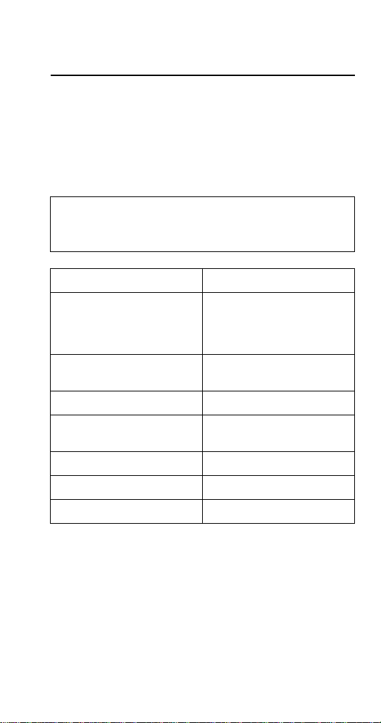
Manager Default Password A
Temperature Control Setting 36°F setpoint 4°F
2°C setpoint 2°C differential
CO
Supply Pressure
2
min / max
CO
Regulator Setting 35 lbs
2
Water supply pressure
min / max
Water Regulator Setting 30 lbs
Ice Capacity 30 lbs (14 kg)
Shipping Weight 430 lbs (195 kg)
Part Number STH034 3/12 23
differential
controlled by software
50 psi / 80 psi
3.5 BAR / 6.2 BAR
30 psi / 90 psi
1.4 BAR / 6.2 BAR
Page 24
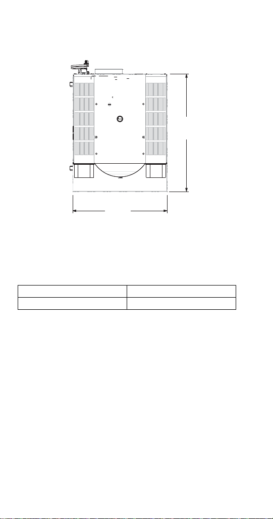
Dimensions
A
B
Elevation View
A 26.00" (66 cm)
B 32.82" (83 cm)
24 Part Number STH034 3/12
Page 25
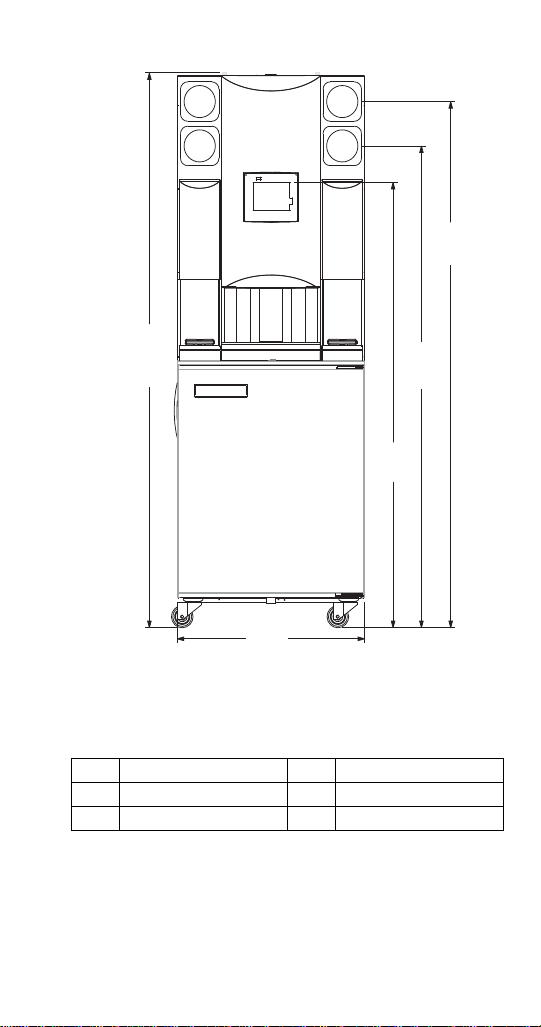
F
H
E
D
C
Elevation View
C 71.19" (181 cm) F 26.00" (66 cm)
D 65.19" (166 cm) H 75.07" (191 cm)
E 60.25" (153 cm)
Part Number STH034 3/12 25
Page 26
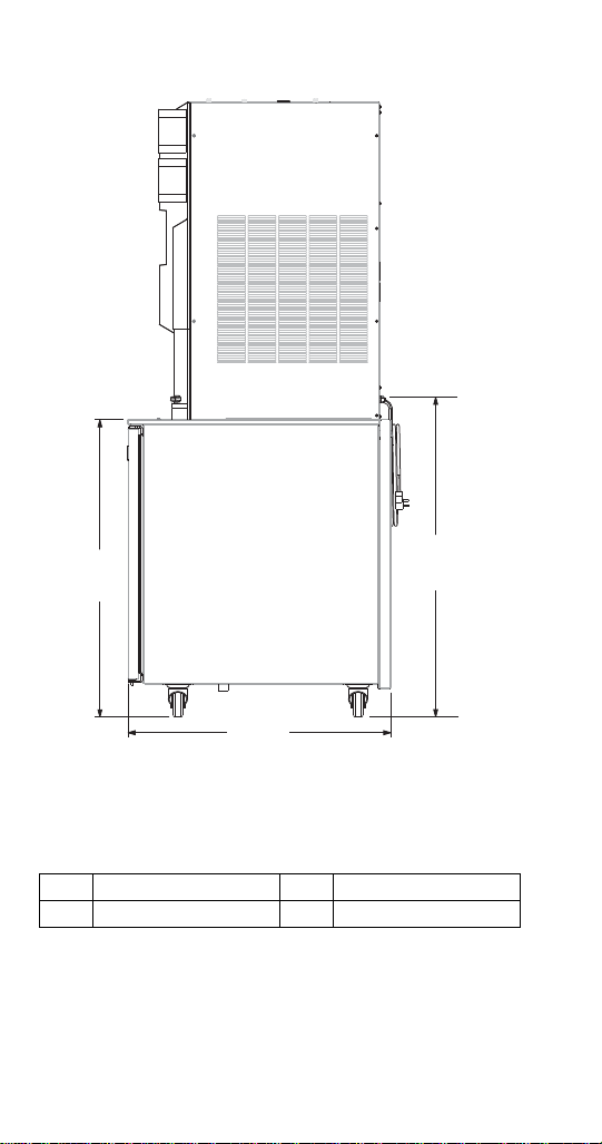
G 32.82" (83 cm) J 39.09" (99 cm)
G
I
J
Side View
I 36.15" (92 cm)
26 Part Number STH034 3/12
Page 27

Location
! Warning
The location selected must meet the following criteria:
• The air temperature must be at least 40°F (4°C),
but must not exceed 90°F (32°C), climate class 4.
• The location must not be near heat-generating
equipment or in direct sunlight and must be
protected from weather.
• Water temperature min/max = 40°F/110°F
(4°C/43°C).
• Water supply pressure min/max = 30 psi/90 psi
(1.4 BAR/6.2 BAR).
• Always use the water supply line supplied when
installing this appliance. Never reuse an old supply
line.
• Main supply CO
Beverage System regulator min/max =
50 psi/80 psi (3.5 BAR/6.2 BAR).
• Minimum clearances must be maintained from all
walls and combustible materials.
• Keep equipment area clear of combustible
material.
Carbon Dioxide (CO2) displaces oxygen.
Exposure to a high concentration of CO
causes tremors, which are followed rapidly by
loss of consciousness and suffocation. If a CO
gas leak is suspected, particularly in a small area,
immediately ventilate the area before repairing
the leak. CO2 lines and pumps must not be
installed in an enclosed space. An enclosed
space can be a cooler or small room or closet.
This may include convenience stores with glass
door self serve coolers. If you suspect CO
build up in an area, venting of the B-I-B pumps
and / or CO2 monitors must be utilized.
pressure to Blend-In-Cup
2
gas
2
may
2
2
Part Number STH034 3/12 27
Page 28

CLEARANCES
!
Warning
Model Air Cooled
Top 18" (46 cm)
Sides 6" (15 cm)
Back 6" (15 cm)
Front 30" (76 cm)
Do not obstruct machine vents or openings.
HEAT OF REJECTION
Heat of Rejection
Model
Air
Conditioning
BTU/h
Peak
Cabinet
All Single & Dual Spindle
Ice Machine
MB-8-1, MB-8-2
MB-8-1E, MB-8-2E
MB-8-1A, MB-8-2A
MB-8-1D, MB-8-2D
MB-8-1U, MB-8-2U
MB-8-1P, MB-8-2P
MB000A01
MB000A02
Ice Machine
MB000A03
MB000A04
MB000A05
28 Part Number STH034 3/12
2100 2600
N/A 5150
N/A 5000
Page 29
Electrical
!
Warning
!
Caution
GENERAL
All wiring must conform to local, state and
national codes.
MINIMUM CIRCUIT AMPACITY
The minimum circuit ampacity is used to help select
the wire size of the electrical supply. The wire size (or
gauge) is also dependent upon location, materials
used, length of run, etc., so it must be determined by a
trained & qualified electrician.
ELECTRICAL REQUIREMENTS
Refer to Model/Serial Plate for voltage/amperage
specifications.
Operate equipment only on the type of electricity
indicated on the specification plate.
Part Number STH034 3/12 29
Page 30

MINIMUM CIRCUIT AMPERAGE CHART
Important
Due to continuous improvements, this information
is for reference only. Please refer to the serial
number tag to verify electrical data. Serial tag
information overrides information listed on this
page.
Model
Numbers
MB-8-1
Dual
Spindle
MB-8-2
Single
Spindle
MB-8-1E
Dual
Spindle
MB-8-2E
Single
Spindle
MB-8-1A
Dual
Spindle
MB-8-2A
Single
Spindle
MB-8-1D
Dual
Spindle
Voltage/Cycle/
Refrigerant
120/60/1
R404A
120/60/1
R404A
230-240/50/1
R404A
230-240/50/1
R404A
230-240/50/1
R404A
230-240/50/1
R404A
230-240/50/1
R404A
Total Amps
16.0 20A
16.0 20A
8.7
8.7
8.7
8.7
8.7
Breaker
Size
20A
20A
20A
20A
20A
30 Part Number STH034 3/12
Page 31

Model
Numbers
Voltage/Cycle/
Refrigerant
Total Amps
Breaker
Size
MB-8-2D
Single
Spindle
MB-8-1U
Dual
Spindle
MB-8-2U
Single
Spindle
MB-8-1P
Dual
Spindle
MB-8-2P
Single
Spindle
MB000A01
Dual
Spindle
MB000A02
Single
Spindle
230-240/50/1
R404A
230-240/50/1
R404A
230-240/50/1
R404A
230-240/50/1
R404A
230-240/50/1
R404A
120V/60/1 16.0
230-240/50/1
R404A
8.7
20A
8.7
20A
8.7
20A
8.7
20A
8.7
20A
20A
8.7
20A
MB000A03
MB000A04
MB000A05
Part Number STH034 3/12 31
120/60/1
R404A
120/60/1
R404A
120/60/1
R404A
16.0 20A
16.0 20A
16.0 20A
Page 32

GROUNDING INSTRUCTIONS
!
Warning
! Warning
This machine must be grounded in accordance
with national and local electrical codes.
This appliance must be grounded. In the event of
malfunction or breakdown, grounding provides a path
of least resistance for electric current to reduce the risk
of electric shock. This appliance is equipped with a
cord having an equipment-grounding conductor and a
grounding plug. The plug must be plugged into an
appropriate outlet that is properly installed and
grounded in accordance with all local codes and
ordinances.
BONDING INSTRUCTIONS 230-240V 50 HZ MODELS ONLY
This appliance must be connected to the potential
equalization system in accordance with EN60335-1
and EN60335-2-75. A bonding lug is provided on the
lower right front corner of the appliance.
This machine must be connected to the potential
equalization system.
32 Part Number STH034 3/12
Page 33

!
Warning
When using electric appliances, basic
precautions must always be followed, including
the following:
a. Read all the instructions before using
the appliance.
b. To reduce the risk of injury, close
supervision is necessary when an
appliance is used near children.
c. Do not contact moving parts.
d. Only use attachments recommended or
sold by the manufacturer.
e. Do not use outdoors.
f. For a cord-connected appliance, the
following must be included:
• Do not unplug by pulling on cord. To
unplug, grasp the plug, not the cord.
• Unplug from outlet when not in use
and before servicing or cleaning.
• Do not operate any appliance with a
damaged cord or plug, or after the
appliance malfunctions or is dropped
or damaged in any manner. Contact
the nearest authorized service facility
for examination, repair, or electrical
or mechanical adjustment.
g. Follow applicable lock out tag out
procedures before working on
equipment.
h. Always unplug before replacing the
lamp. Replace the bulb with the same
type.
i. Connect to a properly grounded outlet
only. See Grounding Instructions.
Part Number STH034 3/12 33
Page 34

Water Supply and Drain Requirements
! Warning
WATER SUPPLY
In most areas, a water filter of some type will be
useful. In areas where the water is highly concentrated
with minerals the water should be tested by a water
treatment specialist, and the recommendations of the
specialist regarding filtration and/or treatment should
be followed.
Connect to a potable water supply only.
WATER INLET LINES
Follow these guidelines to install water inlet lines:
• Use supplied 3/8" panel-mounted hose barb and 6'
(1.8 m) of beverage tubing to connect coupling
body fitting on back of unit into water supply.
• Do not connect to a hot water supply. Be sure all
hot water restrictors installed for other equipment
are working. (Check valves on sink faucets,
dishwashers, etc.)
• Install a water shut-off valve in the water line at the
rear of the machine.
• Insulate water inlet lines to prevent condensation.
• An air gap is included in the design of the machine
for backflow prevention. Local code may require
an additional backflow prevention device.
34 Part Number STH034 3/12
Page 35

DRAIN CONNECTIONS
Follow these guidelines when installing drain lines.
• Connect supplied 1" ID hose to hose-barb
connection on machine.
• Drain lines must have a 1.5 inch drop per 5 feet of
run (2.5 cm per meter), and must not create traps.
• The floor drain must be large enough to
accommodate drainage from all drains.
CO2 Requirements
1. Connection Assembly — Use supplied 3/8"
panel-mounted hose barb and 6' (1.8 m) of
beverage tubing to connect coupling insert on
back of unit into CO
2. Supply pressure — 50 PSI (min.) and 80 PSI
(max.).
3. Product pressure — min. 35 PSI. Lowers the
gas pressure before the CO2 gas flows to the
CO
2
product pump. CO
product pump.
4. Beverage pump — Draws product out of the
product package. Product flows through the lines
to the dispenser for blending and dispensing.
There is a beverage pump for each product.
5. Product cassette — Contains a foil bag filled
with product.
supply.
2
pressure activates the
2
Part Number STH034 3/12 35
Page 36

Step-by-Step Installation
! Warning
1. Visually inspect the exterior of the package and
skid or container. Any damage should be noted
and reported to the delivering carrier immediately.
2. If damaged, open and inspect the contents with
the carrier.
3. In the event that the exterior is not damaged, yet
upon opening there is concealed damage to the
equipment, notify the carrier. Notification should
be made verbally as well as in written form.
4. Request an inspection by the shipping company
of the damaged equipment. This should be done
within 10 days from receipt of the equipment.
5. Check the lower portion of the unit to be sure legs
or casters are not bent.
6. Also open the compressor compartment housing
and visually inspect the refrigeration package. Be
sure lines are secure and base is still intact.
7. Freight carriers can supply the necessary damage
forms upon request.
8. Retain all crating material until an inspection has
been made or waived.
The mass of this appliance will allow it to move
uncontrolled on an inclined surface. Adequate
means must be provided to prevent uncontrolled
movement at all times.
9. Inspect behind the BIC for electrical outlet
location, CO
10. Check voltage at outlet dedicated for BIC.
11. Connect 230-240V 50 hz models to the potential
equalization system.
12. Plug unit in and allow base to start cooling, up to a
five minute delay in start-up is normal.
36 Part Number STH034 3/12
, and water hose fittings and shutoff.
2
Page 37

13. Remove steel top panel. Check that the black
chute cover is sitting securely on the chute. The
ice Machine will not operate properly if it is out of
place.
14. The CO2 and Water Regulator gauges can be
viewed through the panel windows, but the side
panel will require removal if the regulators need
adjustment.
15. Remove other side panel to access board
connections.
16. Install quick disconnect fittings from box of parts
supplied with BIC, on existing supply CO2 and
water hose.
17. Confirm correct orientation of fittings.
18. Install drain hose on BIC and cut to proper length
(do not leave loops in drain).
19. Connect water and CO2 hoses to BIC (quick
disconnect fittings).
20. Coil excess tubing and secure with tie straps.
21. Check water and CO
using).
pressures (check while
2
22. Check that board connections are secure, and did
not vibrate loose during shipment.
23. Check that both micro switches are in line with the
motor above the blenders.
24. Check the blender door sensor positions.
25. Reinstall side panels.
26. Push BIC into place.
Continued on next page …
Part Number STH034 3/12 37
Page 38

27. Check BIC for level and shim if necessary.
28. Install clean, sanitized parts on BIC.
29. Fill all three cleaning pails with warm water, add
soap to wash pail, sanitizer to sanitize pail.
30. Demonstrate to store manager BIC cleaning
procedure.
31. Offer to store manager to add labels to product
bins, put labels in correct place.
32. Demonstrate to store manager how to install cold
product bags into product bins and install into
BIC.
33. Demonstrate to store manager how to load
recipes.
34. Demonstrate to store manager how to calibrate.
35. Demonstrate to store manager how to make
drink.
36. Demonstrate to manager options on control,
manager password is A. The password can be
changed.
37. Set date and time to activate warranty.
38. Complete start-up form, sign, and have store
manager sign form. (Fax to number on form.)
38 Part Number STH034 3/12
Page 39

Installation Checklist
Is the machine level?
Has all of the internal packing been
removed?
Have all of the electrical, water and CO2
connections been made?
Has the supply voltage been tested and
checked against the rating on the
nameplate?
Is there proper clearance around the
machine for air circulation?
Is the machine grounded and polarity
correct?
Has the machine been installed where
ambient temperatures will remain in the
range of 40° – 90°F (4°– 32°C)?
Has the machine been installed where the
incoming water temperature will remain in
the range of 40° – 110°F (4° – 43°C)?
Is the machine cycling on/off on the
temperature control?
Are the regulators set properly?
Has the owner/operator been instructed
regarding maintenance procedures?
230-240V 50hz - Has the potential
equalization system been connected?
Part Number STH034 3/12 39
Page 40

MenuConnect
MenuConnect is used to create recipes for your BlendIn-Cup (BIC) machine. The software is easy to use,
versatile and limited only by your imagination. You will
quickly master the basics and be making all types of
drinks quickly and efficiently. After the recipes are
created, they are copied to a usb drive and transferred
to the Blend-In-Cup machine.
Start-Up Procedures
LOADING RECIPES
Plug in the Flash drive (above upper left corner of
screen). From the Main Menu select Manager. Type in
the password and select the green check. Select the
down arrow to navigate to the next screen. Select
Updates. Select Recipes. Select the UPDATE
RECIPES FROM USB icon. Verify the version to be
loaded is correct, and select the green check. Screen
will display status and then UPDATE COMPLETE.
ASSIGNING FLAVORS
From the Main Menu select Manager. Type in the
password and select the green check. Select
Configure Slots. Select Slot Flavor. Select a slot you
want to assign a flavor to. Select Assign Flavor.
Choose from the list of flavors. Continue to select slots
and flavors until you’re finished. Select the Red X.
Select the return arrow twice to return to the Main
Menu.
40 Part Number STH034 3/12
Page 41

LOADING BAGS
From the Main Menu select Inventory. One at a time
select the slots with assigned flavors.
1. Position rear groove of the spout on product bag
into slot of the product bin.
2. The spout must snap into slot of product bin.
3. Open the cap on the product bag and tear it off.
4. Return product bin to its position in cabinet.
Select the green check. Select Full Bag. Place cup
under dispenser. Select the pump icon. Dispensing will
display on the screen. If a small amount of product has
been pumped into the cup, select the green check. If
no product was pumped through to the cup, select the
pump icon again, confirm product has been pumped
through and then select the green check. Continue
through all the slots that have been assigned flavors.
Select the return arrow when complete.
Calibration Procedure
• From the main menu select the manager icon.
• Enter the manager’s password.
• Select Configure Slots.
Part Number STH034 3/12 41
Page 42

• Select Calibrate Flavor.
• Select the flavor, water or ice to calibrate.
1. Get Scale
2. Tare Empty Cup Weight
3. Position Cup For Dispense
Flavor and water target is 4 oz. Ice target is 6 oz.
1. Wait until dispensing is done
2. Weigh cup
42 Part Number STH034 3/12
Page 43

3. Tap button to enter weight.
• Enter the cup weight.
• Select the green arrow.
• The calibration screen will return, select the green
arrow.
Part Number STH034 3/12 43
Page 44

• Flavor, 4 oz. Calibration Complete
• The calibration screen returns. Chose another
flavor, water or ice to calibrate or return to the
Configure Slots screen.
44 Part Number STH034 3/12
Page 45

Maintenance
! Warning
General Maintenance
Disconnect power to the unit before performing
any service or maintenance functions.
DOOR GASKET MAINTENANCE
Door gaskets require regular cleaning to prevent mold
and mildew buildup and also to retain the elasticity of
the gasket. Gasket cleaning can be done with the use
of warm soapy water. Avoid full strength cleaning
products on gaskets as this can cause them to
become brittle and crack. Never use sharp tools or
knives to scrape or clean the gasket. Gaskets can be
easily replaced and do not require the use of tools or
an authorized service person. The gaskets are “Dart”
style and can be pulled out of the groove in the door
and new gaskets can be “pressed” back into place.
DRAIN MAINTENANCE - BASE
Each unit has a drain located inside the unit that
removes the condensation from the evaporator coil
and routes it to an external condensate evaporator
pan. Each drain can become loose or disconnected
during normal use. If you notice water accumulation on
the inside of the unit, be sure the drain tube is
connected to the evaporator drain pan. If water is
collecting underneath the unit, make sure the end of
the drain tube is in the condensate evaporator in the
machine compartment. The leveling of the unit is
important as the units are designed to drain properly
when level. Be sure all drain lines are free of
obstructions.
Part Number STH034 3/12 45
Page 46

CASTER MAINTENANCE
Important
Wipe casters with a damp cloth monthly to prevent
corrosion.
NOTE: The power switch must be turned to OFF and
the unit disconnected from the power source
whenever performing service, maintenance functions
or cleaning the refrigerated area.
REFRIGERATORS
The interior and exterior can be cleaned using soap
and warm water. If this isn’t sufficient, try ammonia and
water or a nonabrasive liquid cleaner. When cleaning
the exterior, always rub with the “grain” of the stainless
steel to avoid marring the finish. Do not use an
abrasive cleaner because it will scratch the stainless
steel and can damage the breaker strips and gaskets.
STAINLESS STEEL CARE AND CLEANING
To prevent discoloration or rust on stainless steel,
several important steps need to be taken. First, we
need to understand the properties of stainless steel.
Stainless steel contains 70-80% iron, which will rust. It
also contains 12-30% chromium, which forms an
invisible passive film over the steel’s surface, which
acts as a shield against corrosion. As long as the
protective layer is intact, the metal is still stainless. If
the film is broken or contaminated, outside elements
can begin to break down the steel and begin to form
discoloration or rust. Proper cleaning of stainless steel
requires soft cloths or plastic scouring pads.
Never Use Steel Pads, Wire Brushes or
Scrapers!
46 Part Number STH034 3/12
Page 47

Cleaning solutions need to be alkaline based or non-
!
Caution
chloride cleaners. Any cleaner containing chlorides will
damage the protective film of the stainless steel.
Chlorides are also commonly found in hard water,
salts, and household and industrial cleaners. If
cleaners containing chlorides are used, be sure to
rinse repeatedly and dry thoroughly. Routine cleaning
of stainless steel can be done with soap and water.
Extreme stains or grease should be cleaned with a
non-abrasive cleaner and plastic scrub pad. Always
rub with the grain of the steel. There are stainless steel
cleaners available which can restore and preserve the
finish of the steel’s protective layer. Early signs of
stainless steel breakdown are small pits and cracks. If
this has begun, clean thoroughly and start to apply
stainless steel cleaners in attempt to restore the
passivity of the steel.
Never use an acid based cleaning solution! Many
food products have an acidic content, which can
deteriorate the finish. Be sure to clean the
stainless steel surfaces of ALL food products.
Common items include: tomatoes, peppers and
other vegetables.
Part Number STH034 3/12 47
Page 48

CLEANING THE CONDENSER COIL
!
Caution
In order to maintain proper refrigeration performance,
the condenser fins must be cleaned of dust, dirt and
grease regularly. It is recommended that this be done
at least every three months. If conditions are such that
the condenser is totally blocked in three months, the
frequency of cleaning should be increased. Clean the
condenser with a vacuum cleaner or stiff brush. If
extremely dirty, a commercially available condenser
cleaner may be required.
Failure to maintain a clean condenser coil can initially
cause high temperatures and excessive run times.
Continuous operation with a dirty or clogged
condenser coil can result in compressor failure.
Neglecting the condenser coil cleaning procedures will
void any warranties associated with the compressor
and cost to replace the compressor.
Never use a high-pressure water wash for this
cleaning procedure as water can damage the
electrical components located near or at the
condenser coil.
48 Part Number STH034 3/12
Page 49

DOORS/HINGES
Over time and with heavy use doors and hinges may
become loose. If this happens tighten the screws that
mount the hinge brackets to the frame of the unit.
Loose or sagging doors can cause the hinges to pull
out of the frame, which may damage both the doors
and the hinges. In some cases this may require
trained & qualified service agents or maintenance
personnel to perform repairs.
NOTE: Do not place hot pans on/against the blue ABS
liner. Do not throw items into the storage area. Failure
to follow these recommendations could result in
damage to the interior of the cabinet or to the blower
coil. Overloading the storage area, restricting the
airflow, and continuous opening and closing of the
doors and drawers will hamper the unit’s ability to
maintain operational temperature.
PREVENTING BLOWER COIL CORROSION
Immediately wipe up all spills.
ANNUAL PLANNED MAINTENANCE
The following parts are recommended for annual
planned maintenance replacement to ensure optimum
unit performance and minimize downtime:
• Refrigerator door gasket (cleaning may be
sufficient)
• (2) #6 O rings for the water and CO
connect lines
/air quick
2
• (9) LMS valves
• (1 Or 2) Mixer assemblies
Part Number STH034 3/12 49
Page 50

CLEANING KITS
Complete cleaning kits are available for single
and dual spindle units.
These kits include the following;
• (3) three 5 gallon buckets
• Bucket labels for Wash, Rinse, & Sanitizing
• Red & Blue cups for blender cleaning
• Dispense Area Shield
• Tubing Manifold for product line cleaning
50 Part Number STH034 3/12
Page 51

Daily Cleaning
On the Menu screen, press the
washing hand (cleaning icon).
Press Daily.
Gather the following supplies:
Clean towels
Spray cleaner (KAY®
SolidSense All Purpose
Super Concentrate, min.
0.085 oz/gal. or 0.425 oz/5
gal*)
Spray sanitizer (KAY-5®
Sanitizer/Cleaner, min.
0.40 oz/gal or 2.0 oz/5
gal*)
Medium cups with wash
and sanitize solution
Press the down arrow to
continue.
*If other cleaners are used, it is
possible they will not clean or
sanitize your machine to NSF
standards.
Grate removal/mixer station wash:
1 Remove grate from left
and right mixer stations
2 Spray all mixer station
inside surfaces with
cleaning solution
Part Number STH034 3/12 51
Page 52

3 Thoroughly wipe down all
surfaces of mixer station
4 Repeat for the other side
Press the down arrow to
continue.
Dispensing area cleaning:
1 Remove center grate from
dispensing area
2 Spray all dispensing area
surfaces with cleaning
solution
3 Thoroughly wipe down all
surfaces of dispensing
area and verify dispense
area drains completely
Press the down arrow to
continue.
4 Thoroughly spray each
individual dispense nozzle
with cleaning solution
5 Thoroughly wipe with a
clean towel
Press the down arrow to
continue.
52 Part Number STH034 3/12
Page 53

Mixer door removal:
1 Slightly open mixer door
2 Squeeze at bottom of door
3 Tilt out and pull the door
down and out
4 Repeat for other door
Press the down arrow to
continue.
Blender assembly wash:
1 Completely spray blender
assembly with cleaning
solution
2 Thoroughly wipe down top
of blender cap and blender
arm
3 Lift blender cap and
thoroughly wipe down top
of blade housing and
bottom of blender cap
4 Thoroughly spray blender
assembly with sanitizer
solution
5 Repeat for other side
Press the down arrow to
continue.
Part Number STH034 3/12 53
Page 54

Reinstall grates/doors:
1 Take all grates and doors
to sink to wash and
sanitize
2 Do not put in dishwasher
or power soaker
3 Reinstall left and right
mixer grates
4 Reinstall dispensing area
grate
5 Reinstall left and right
mixer doors
Press the down arrow to
continue.
Blender wash:
1 Place cup with wash
solution in both blender
stations
Close the blender doors
2 Press the green check
The blenders will lower into the
wash solution and spin to clean.
Washing will display on the
screen
Follow the on screen
instruction, Remove Cup.
Follow the on screen
instruction, Close Door.
54 Part Number STH034 3/12
Page 55

Rinsing will display on the
screen while the machine rinses
the blenders
Finished will display on the
screen
Blender sanitizing:
1 Pour wash solution down
the drain
2 Place cup with sanitizer
solution in both blender
stations
3 Press the green check
Sanitizing will display on the
screen
Mixer station sanitize:
1 Remove cup from each
blender station and pour
sanitizing solution down
the drain and verify
dispense area drains
completely
2 Spray all mixer station
inside surfaces with
sanitizer solution
3 Allow to air dry
4 Do not wipe off sanitizer!
5 Repeat for other side
Press the down arrow to
continue.
Part Number STH034 3/12 55
Page 56

Dispensing area sanitizing:
1 Thoroughly spray each
individual dispense nozzle
with sanitizer solution
2 Thoroughly spray
dispense area with
sanitizer solution
3 Allow to air dry
4 Do not wipe off sanitizer!
Cleanup any spills on or around
he unit, then press the green
check to signify you have
completed the daily cleaning.
Weekly Cleaning
On the Menu screen, press the
washing hand (cleaning icon).
Press Weekly.
Gather the following supplies:
1 Clean towels
2 Spray cleaner (KAY®
56 Part Number STH034 3/12
SolidSense All Purpose
Super Concentrate, min.
0.085 oz/gal. or 0.425
oz/5 gal*)
Page 57

3 Spray sanitizer (KAY-
5® Sanitizer/Cleaner,
min. 0.40 oz/gal or 2.0
oz/5 gal*)
4 Medium cups with wash
and sanitize solution
Press the down arrow to
continue.
5 Buckets with wash,
rinse and sanitize
solution
6 Splash shield
7 Cleaning manifold
Press the down arrow to
continue.
*If other cleaners are used, it is
possible they will not clean or
sanitize your machine to NSF
standards.
Washing instructions:
1 Remove grate from
2 Install splash guard in
3 Remove product
4 Take product holders to
Press the down arrow to
continue.
center dispensing area
dispense area
holders from cabinet
walk-in refrigerator
Part Number STH034 3/12 57
Page 58

5 Spray and wipe each bib
connector and area with
cleaner
6 Spray each bib
connector and area with
sanitizer
7 Connect a cleaning
hose to each product
nozzle
8 Place cleaning manifold
in wash bucket
9 Press the green check
Select Manual Clean or Auto
Clean
Auto clean will send the wash
solution through each line (slot),
displaying the progress on the
screen.
Manual Clean forces you to
select each slot separately to
send the wash solution through
that line. Each slot will display
Washed as you progress.
Press the green check
58 Part Number STH034 3/12
Page 59

Rinsing instructions:
1 Remove cleaning
manifold from wash
bucket
2 Place cleaning manifold
in rinse bucket
3 Press the green check
Rinse solution runs through
each line (slot). The screen will
read Rinsing Slot X. Each slot
will change from Washed to
Rinsed.
Sanitization instructions:
1 Remove cleaning
manifold from rinse
bucket
2 Place cleaning manifold
in sanitize bucket
3 Press the green check
Sanitizing solution runs through
each line (slot). The screen will
read Sanitizing Slot X. Each slot
will change from Rinsed to
Sanitizing.
Part Number STH034 3/12 59
Page 60

Pause for the Sanitation Hold
Time.
Purging instructions:
1 Disconnect the cleaning
hoses from the product
nozzles
2 Press the green check
Air is pushed through each line
(slot) blowing out any remaining
liquid. The screen will read
Purging Slot X. Each slot will
change from Sanitized to
Purged.
Reinstall inventory:
1 Retrieve product
holders from walk in
2 Reinstall each product
holder into correct slot
3 Remove splash guard
4 Reinstall center grate
Press the down arrow to
continue.
5 Place a large cup under
60 Part Number STH034 3/12
from dispense area
under dispensing area
dispensing nozzles
Page 61

6 Press the green check
Each line will fill with product.
The screen will read Priming
Slot X. Each slot will change
from Purged to Clean.
Grate removal/mixer station wash:
1 Remove grate from left
and right mixer stations
2 Spray all mixer station
inside surfaces with
cleaning solution
3 Thoroughly wipe down
4 Repeat for other side
Press the down arrow to
continue.
all surfaces of mixer
station
Dispensing area cleaning:
1 Remove center grate
2 Spray all dispensing
3 Thoroughly wipe down
Part Number STH034 3/12 61
from dispensing area
area surfaces with
cleaning solution
all surfaces of
dispensing area and
verify dispense area
drains completely
Page 62

Press the down arrow to
continue.
4 Thoroughly spray each
individual dispense
nozzle with cleaning
solution
5 Thoroughly wipe with a
clean towel
Press the down arrow to
continue.
Mixer door removal:
1 Slightly open mixer door
2 Squeeze at bottom of
door
3 Tilt out and pull the door
down and out
4 Repeat for other door
Press the down arrow to
continue.
62 Part Number STH034 3/12
Page 63

Blender assembly wash:
1 Completely spray
blender assembly with
cleaning solution
2 Thoroughly wipe down
top of blender cap and
blender arm
3 Lift blender cap and
thoroughly wipe down
top of blade housing
and bottom of blender
cap
4 Thoroughly spray
blender assembly with
sanitizer solution
5 Repeat for other side
Press the down arrow to
continue.
Reinstall grates/doors:
1 Take all grates and
doors to sink to wash
and sanitize
2 Do not put in
dishwasher or power
soaker
3 Reinstall left and right
mixer grates
4 Reinstall dispensing
5 Reinstall left and right
Part Number STH034 3/12 63
area grate
mixer doors
Page 64

Press the down arrow to
continue.
Blender wash:
1 Place cup with wash
solution in both blender
stations
Close the blender doors
2 Press the green check
The blenders will lower into the
wash solution and spin to clean.
Washing will display on the
screen
Follow the on screen instruction,
Remove Cup.
Follow the on screen instruction,
Close Door.
Rinsing will display on the
screen while the machine rinses
the blenders
Finished will display on the
screen
64 Part Number STH034 3/12
Page 65

Blender sanitizing:
1 Remove cup from each
blender station and pour
wash solution down the
drain and verify
dispense area drains
completely
2 Place cup with sanitizer
solution in both blender
stations
3 Press the green check
Sanitizing will display on the
screen
Mixer station sanitize:
1 Remove cup from each
blender station and pour
sanitizing solution down
the drain
2 Spray all mixer station
inside surfaces with
sanitizer solution
3 Allow to air dry
4 Do not wipe off
5 Repeat for other side
Press the down arrow to
continue.
Part Number STH034 3/12 65
sanitizer!
Page 66

Dispensing area sanitizing:
1 Thoroughly spray each
individual dispense
nozzle with sanitizer
solution
2 Thoroughly spray
dispense area with
sanitizer solution
3 Allow to air dry
4 Do not wipe off
sanitizer!
Cleanup any spills on or around
he unit, then press the green
check to signify you have
completed the daily cleaning.
Weekly cleaning completed:
1 Weekly cleaning has
been completed
2 Unit will need to be
cleaned again in 7 days
3 Press the green check
The Weekly cleaning has been
completed. The screen will
return to the Menu Screen.
66 Part Number STH034 3/12
Page 67

Ice Machine Cleaning
VERSION 1 ICE MACHINE R404A REFRIGERANT
The ice machine must be cleaned and sanitized at
least twice a year. More frequent cleaning may be
required in some existing water conditions.
The parts listed below should be inspected at least
once a year or every 10,000 hours of operation. Their
service life, however, depends on water quality and
environment. More frequent inspection and
maintenance are recommended. To have the optimum
performance of this ice Machine, the following
consumable parts need periodic inspection,
maintenance and replacement:
• Extruding Head
• Housing
• Lower Bearing
• Gear Motor
• Auger
• Mechanical Seal
To prevent injury to individuals and damage to the ice
Machine, do not use ammonia type cleaners.
Follow carefully any instructions provided with the
bottles of Ice Machine cleaner or sanitizing solution.
Always wear liquid-proof gloves to prevent the
cleaning and sanitizing solutions from coming into
contact with skin.
1. Flip the rocker switch to “Drain” position. This
switch is the lower switch on the back of the unit.
2. Remove the unit top by removing four
thumbscrews.
3. Remove ice chute cover.
Part Number STH034 3/12 67
Page 68

4. Remove ice dispense motor assembly by
removing four thumbscrews. Place motor
assembly in a location that it will not fall.
5. Remove ice chute by removing two thumbscrews.
There is a gasket between the ice chute and ice
extruding head, remove it.
6. Remove ice bin cover and place cover in a
location that it will not fall.
7. Remove all ice manually and discard. Be cautious
of the washer in between the ice agitator and the
bottom of the ice bin.
8. Use an approved cleaning solution as noted
below.
NOTE: For safety and maximum effectiveness, use
the solution immediately after dilution.
Mix 10 fl. oz. (296 ml) “LIME-A-WAY” (Economics
Laboratory, Inc.) with 2 gallon (6 l) of warm water
or follow the dilution instructions and warnings on
descaler bottle.
9. Use an approved sanitizing solution or mix 1
ounce of household bleach to 2 gallons of warm
(95°F-115°F) water.
10. Remove ice agitator. clean, rinse and sanitize the
ice agitator.
11. Remove the dispense wheel assembly.
12. Locate small washer, it will be stuck to the
bushing or inside the agitator shaft.
68 Part Number STH034 3/12
Page 69

13. Soak the following parts for 20 minutes in
cleaning solution. Rinse the parts thoroughly.
Soak the removed parts in sanitizing solution for
10 minutes and wipe them down.
If solution is left on these parts, they will rust.
• 2 chute parts
• gasket
• dispense wheel and housing
• small washer
14. Wipe the inner ice bin wall with cleaning solution.
Rinse with a clean towel soaked in clean water
and wipe dry. Repeat with sanitizer solution.
Rinse with a clean towel soaked in clean water
and wipe dry.
15. With a bottle brush, brush the ice nozzle at bottom
of ice bin with cleaning solution. Rinse with a
clean towel soaked in clean water and wipe dry.
Repeat with sanitizer solution. Rinse with a clean
towel soaked in clean water and wipe dry.
16. Use an approved Ice Machine cleaning solution
as noted below.
NOTE: For safety and maximum effectiveness, use
the solution immediately after dilution.
Mix 5 fl. oz. (142 ml) “LIME-A-WAY” (Economics
Laboratory, Inc.) with 1 gallon (3 l) of warm water
or follow the dilution instructions and warnings on
an ice machine descaler bottle.
Part Number STH034 3/12 69
Page 70

17. Turn OFF the ice Machine power switch located
on the back.
18. Slowly pour 1 gallon of cleaning solution into the
top of the freeze barrel where the ice normally
exits.
19. Allow the ice Machine to sit for about 20 minutes.
20. After 20 minutes, turn ON the ice Machine power
switch.
21. After the cleaning solution is drained, roughly two
minutes, move the rocker switch to the “ICE”
position.
22. Allow the reservoir to fill with fresh water. Move
the rocker switch to the “Drain” position for 2
minutes.
23. Repeat fill and drain process again by moving the
rocker switch to the “ICE” position. Allow the
reservoir to fill with fresh water. Move the rocker
switch to the “Drain” position for 2 minutes.
24. Turn OFF the ice Machine power switch.
25. Use an approved sanitizing solution or mix 1
ounce of household bleach to 2 gallons of warm
(95°F-115°F) water.
70 Part Number STH034 3/12
Page 71

26. Fill the freeze barrel with sanitizing solution where
the ice normally exits.
27. Allow the ice Machine to sit for about 10 minutes.
28. Replace ice chute, gasket and (2) black
thumbscrews.
29. Lay the unit top over the bin overflow switch. The
bin overflow switch must be depressed for the ice
machine to work properly.
30. Turn ON the ice Machine power switch.
31. Move the rocker switch to the “ICE” position.
32. Run the ice Machine for 20 minutes.
33. Turn OFF the ice Machine power switch.
34. Remove ice chute in order to replace parts.
NOTE: Discard the ice. Do not use ice made from the
sanitizing solution. Be careful not to leave any ice or
solution in the storage bin.
35. Rinse bin with water.
36. Replace all cleaned parts in their correct
positions:
• small washer
• assembled dispense wheel/plates
• auger
• bin cover
• motor
• gasket
• ice chute
• ice chute cover.
37. Replace the unit top cover with four thumbscrews.
38. Cleanup any spills on or around the unit.
39. Turn ON the ice Machine power switch.
Part Number STH034 3/12 71
Page 72

VERSION 2 ICE MACHINES R404A OR R290 REFRIGERANT
The ice machine must be cleaned and sanitized a
minimum of once every six months. More frequent
cleaning may be required in some existing water
conditions. Always wear liquid-proof gloves and safety
glasses to prevent the cleaning and sanitizing
solutions from coming into contact with skin or eyes.
Use Manitowoc Ice Machine Cleaner part number
000000084.
Use Manitowoc Ice Machine Sanitizer part number
94-0565-3.
1. Turn off the ice making water supply and
disconnect power.
2. Remove the following parts:
• Top by removing four thumbscrews.
• Ice chute cover.
• Ice dispense motor assembly by removing
four thumbscrews -Place motor assembly in a
location that it will not fall.
• Ice chute by removing two thumbscrews.
There is a gasket between the ice chute and
ice extruding head that also needs to be
removed.
• Remove ice bin cover and place cover in a
location that it will not fall
• Remove all ice manually. Be cautious of the
washer in between the ice agitator and the
bottom of the ice bin.
3. Remove the following parts for cleaning and
sanitizing:
• Ice agitator
• Dispense wheel assembly
• Small washer - It will be stuck to the bushing
or inside the agitator shaft.
72 Part Number STH034 3/12
Page 73

4. Soak the parts in cleaning solution, then rinse the
parts thoroughly.
5. Soak the parts in sanitizing solution and allow to
air dry.
6. Wipe the inner ice bin wall with cleaning solution,
rinse and wipe dry. Repeat with sanitizer solution
and allow to air dry.
7. Use a bottle brush and cleaning solution to clean
the ice nozzle at bottom of ice bin. Rinse, wipe
dry, repeat with sanitizer solution and allow to air
dry.
8. Drain water from evaporator and reservoir
through the evaporator/reservoir drain line and
reinsert hose into hose clip.
9. Follow the chart and premix cleaner and water.
Amount of Luke Warm
Water
Amount of Cleaner
Part Number 000000084
1 gallon (4 Liters) 4 ounces (120 ml)
10. Remove top cover from the water reservoir, block
up reservoir float and fill the evaporator and
reservoir with cleaning solution. Remainder of
solution will be used for hand cleaning.
Part Number STH034 3/12 73
Page 74

11. Verify the compressor rocker switch is in the OFF
position, then reconnect power and run the
gearmotor for 15 minutes. Perform the following
procedures during the 15 minute period:
• Remove ice compression nozzle from
evaporator and soak in cleaning solution.
• Descale drain pan by gently flexing, then
remove any scale residue.
• Inspect water feed and drain lines and clean
as needed.
• Connect ice transport tube direct to
evaporator and secure with hose clamp.
12. Disconnect power, then drain the water from the
evaporator and reservoir through the evaporator/
reservoir drain line - Using a pitcher, fill and drain
the evaporator/reservoir 4 times and reinsert the
hose into the hose clip.
13. Refer to chart and premix water and sanitizer.
Amount of
Luke Warm Water
Amount of Sanitizer
1 Gallon (4 L) Water 1/2 ounce (15 ml)
14. Fill reservoir and evaporator with sanitizer/water
solution.
15. Verify the compressor rocker switch is in the OFF
position, then reconnect power and run the
gearmotor for 10 minutes.
74 Part Number STH034 3/12
Page 75

16. During the 10 minute period rinse cleaner from
compression nozzle with potable water and then
soak in sanitizer/water solution.
17. Move the compressor rocker switch to the ON
position. The ice machine will make ice with the
sanitizer/water solution and deposit the ice in the
bin/dispenser. Make ice for 5 minutes - add
sanitizer/water solution as the water level in the
reservoir drops.
NOTE: Do not allow the sanitizer/water level to drop
below the sensing probes. The ice machine will start a
20 minute delay period if the sensing probes lose
contact with the water for more than 10 seconds.
18. Move the compressor rocker switch to the OFF
position and disconnect power.
19. Drain the evaporator/reservoir and reinsert the
drain hose into the hose clip.
20. Reinstall the ice compression nozzle and
reservoir cover.
21. Remove blocking from under reservoir float and
reinstall reservoir cover.
Part Number STH034 3/12 75
Page 76

22. Turn on the ice making water supply, reconnect
power and move the compressor rocker switch to
ON.
23. Allow the ice machine to run for 10 minutes, then
place the compressor rocker switch in the OFF
position, disconnect power and discard all ice
produced.
24. Turn ON the ice Machine power switch.
25. Replace all cleaned parts in their correct
positions:
• small washer
• assembled dispense wheel/plates
• auger
• bin cover
•motor
• gasket
• ice chute
• ice chute cover.
26. Replace the unit top with four thumbscrews and
cleanup any spills on or around the unit.
27. Reinstall all removed panels and restore power.
76 Part Number STH034 3/12
Page 77

Operation
Recipe/Menu
Manager
Cleaning
Inventory
Touch Screens
“easy ToUCH” Screen. The main screen has four
selections. The book icon is the drink making
procedure (recipe/menu). The manager screen
accesses machine settings. Inventory and cleaning
are the other selections accessed through the main
screen.
Inventory Screen. The inventory screen visually
displays levels for all flavors. Underneath each flavor
is the time remaining until the flavor expires. Nozzle
and cabinet temperatures are also on the inventory
screen. When a flavor is touched on the screen the
instructions to replace a product bag will begin.
Part Number STH034 3/12 77
Page 78

Manager Screens
The manager screens are password protected. After
typing in the correct password the following screens
are accessible: Language, Date/Time, Temperatures,
Edit Password, Configure Slots, Updates, Auto Wash
Timer and Service. When the manager screens are
inactive for a time period, the screen will return to the
drink menu.
The service screen is password protected and
removes all data from control board memory. The
control board will require complete setup and
programming after the service screen is accessed.
Contact the factory for troubleshooting information and
access to the service screen.
78 Part Number STH034 3/12
Page 79

Date/Time. Set the correct date and time at
installation. Correct the date or time when necessary.
T emperatures. The nozzle, cabinet and defrost
temperatures will help diagnose refrigeration
problems.
Configure Slots. Slot Flavor allows the manager to
assign flavors to slots. Calibrate Flavor is a process to
ensure the machine is dispensing the correct amount
from each product slot, water and ice.
Part Number STH034 3/12 79
Page 80

Updates. Firmware and Recipes Screens allow the
manager to plug a USB flash drive in and upload new
firmware and recipes.
Auto Wash Timer. Allows the manager to turn on or
off and set up periodic automatic wash, clean and
sanitize cycles for the blender stations.
80 Part Number STH034 3/12
Page 81

Recommended Cups
Although a variety of cups may work in the BIC
machine, the most success (without cup cracking) has
come from polyethylene (PETE) cups. Other varieties
such as glass, polypropylene, and thick walled
styrofoam have also proven workable. Cup thickness,
material composition, diameter and cup height play an
important role in the workability of the cup within the
machine.
The following are cup general guidelines. Cups
outside these parameters may work — testing in the
machine with the product will be necessary.
• Cup heights between 4.25" and 7.00".
• Cup opening diameter greater than 3.50" and less
than 4.18".
• Cup base diameter greater than 2.38" and less
than 2.62".
Part Number STH034 3/12 81
Page 82

Procedure to Make a Drink
1. From the menu screen, press the book icon.
2. Select a category of recipes.
3. Specific drink combinations are displayed on the
next screen. If a drink is not available it will be
highlighted with a red square around it. The drink
is not available because:
The flavor was not assigned.
82 Part Number STH034 3/12
Page 83

4. Drink size is the next selection.
5. Place cup under center dispenser.
6. Press the green check.
7. As the flavor dispenses into the cup, the screen
will display DISPENSING.
8. If ingredients need to be manually added, the
screen will give specific directions. More
ingredients may be required later, follow the
screen directions.
Part Number STH034 3/12 83
Page 84

9. Choose an available mixer and place the cup into
the module and shut the door. Press the
corresponding right or left flashing green/blue
arrow.
10. While the drink is mixing, the screen will read
Blending.
11. Follow all drink specific screen directions and
press the flashing arrow.
12. When the blender is done mixing. Open the door
and remove the drink. The blending station will go
through a wash, rinse and sanitize cycle.
84 Part Number STH034 3/12
Page 85

Procedure to Replace a Product Bag
1. From the main menu touch the inventory icon.
2. On the inventory screen select the product to be
replaced.
Products with less than 10% inventory or less
than 24 hours until product expires will be
displayed with a yellow bar.
Products that are expired will be displayed with a
red bar.
3. Remove product bin from cabinet and discard
empty bag.
4. Wipe the inside of the product bin with a clean
towel.
5. Place new product bag with the spout facing down
into product bin.
Part Number STH034 3/12 85
Page 86

6. Position rear groove of the spout on product bag
into slot of the product bin.
7. The spout must snap into slot of product bin.
8. Open the cap on the product bag and tear it off.
9. Return product bin to its position in cabinet.
10. Select inventory level from full bag, prime flavor or
no bag.
86 Part Number STH034 3/12
Page 87

11. Place cup under dispenser and hold icon to prime.
12. Select another product to be replaced or return to
the previously active screen.
Part Number STH034 3/12 87
Page 88

Firmware Update Procedure
Important
1. Read Instructions Completely
2. Firmware file (.bin) must be loaded on top level
of flash drive.
3. Require only 1 firmware (.bin) file on the flash
drive at a time. If multiple firmware (.bin) files
are on the flash drive, the first one in
alphabetical order would be loaded and may
not be the current version.
5. Flash Drive must be formatted to FAT or FAT16
file format. (Typical for smaller flash drives
<1GB).
1 Plug in Flash Drive (above
upper left corner of
screen).
2 Press the Managers Icon.
3 Enter Password, “A”.
4 Press the Green Check.
5 Press the Page Down
Icon.
88 Part Number STH034 3/12
Page 89

6 Press the UPDATES Icon.
Important
7 Press the FIRMWARE
Icon.
8 Press the USER
INTERFACE Icon.
9 Verify version to be loaded
is correct, and press the
Green Check.
10 Firmware will show status
of update as a percentage,
and screen will display
“UPDATE COMPLTE”
when finished.
You must CYCLE POWER to the unit after a
firmware update before the firmware will take
effect.
Part Number STH034 3/12 89
Page 90

Ice Making Sequence of Operation
VERSION 1 ICE MACHINE R404A REFRIGERANT
INITIAL START-UP
1. Placing the power switch in the “ON” position and
the flush switch in the “ICE” position, will supply
water to the reservoir.
2. The reservoir fills with water, the low water switch
closes and the gear motor starts.
FREEZE CYCLE
3. After the gear motor runs for 60 seconds the
compressor will start. The gear motor,
compressor, condenser fan motor and low water
switch remain energized as the ice machine
makes ice. The water float valve will open and
close automatically to maintain the proper water
level.
AUTOMATIC SHUT-OFF
4. The infrared bin control senses ice for 6
continuous seconds and starts a 90 second delay
period, After the 90 second delay period, the
compressor stops. 90 seconds after the
compressor stops the gear motor will stop.
RESTART AFTER AUTOMATIC SHUT-OFF
The gear and fan motor energize for 60 seconds to
clear the evaporator of any remaining ice and to
provide short cycle protection. 60 seconds later the
compressor energizes, starting a freeze cycle.
DRAIN CYCLE IN THE “ON” POSITION
After the ice machine has run for 12 hours the ice
machine will stop making ice and start a drain cycle.
The drain cycle will remove minerals that have settled
in the bottom of the evaporator. The drain cycle lasts
approximately 20 minutes, after which the ice machine
control board automatically resumes ice making and
resets the 12 hour counter to zero.
90 Part Number STH034 3/12
Page 91

DRAIN CYCLE MANUAL OPERATION
Move ICE/DRAIN switch to DRAIN
If the ice machine is running:
90 seconds after the flush switch is moved to the
“Drain” position, the flush valve opens. and flushes the
reservoir and evaporator. The drain cycle continues
until the switch is moved to the “Ice” position.
If the ice machine is not running:
The drain valve opens immediately. The drain cycle
continues until the switch is moved to the “Ice”
position.
Part Number STH034 3/12 91
Page 92

VERSION 2 ICE MACHINES R404A OR R290 REFRIGERANT
NOTE: Ice machines use an auger to remove ice from
the evaporator. Occasional noises (creaks, groans,
squeaks, or pops) are a normal part of the ice making
process.
Operation
The ice machine will not start until:
A. The compressor rocker switch is moved to
“ON”.
B. Ice does not contact the bin thermostat bulb.
C. The water reservoir is full of water.
With power supplied and the compressor rocker
switch in the ON position, the gear motor and
refrigeration system start. The float valve controls the
water inlet valve and water level. The freeze cycle
ends when ice contacts the bin thermostat. A
20 minute delay period initiates. The ice machine will
restart when ice no longer contacts the bin thermostat
and the 20 minute delay period expires.
92 Part Number STH034 3/12
Page 93

Product Dispense Operation
The sequence varies according to the recipe. Some
recipes will use one ingredient, others will use multiple
ingredients. The sequence below uses one ingredient
to simplify the sequence.
Prerequisites
• Line voltage must be supplied
•CO
• Product is inserted in cabinet and correctly
• Ice is available
• Water is supplied at the correct pressure
• A recipe has been developed in MenuConnect and
OPERATION
Selecting a drink from the touch screen will energize
the following components for the time specified by the
recipe:
The cup is then transferred to a blending station.
pressure is supplied and regulated to the
2
correct pressure
connected to adapter/tubing
transferred to the control board with a usb drive.
A. The ice dispense wheel turns to add ice.
B. The water inlet valve opens to dispense
water.
C. The solenoid valve opens and supplies CO
to the product pump
D. The product pump energizes and pumps the
product.
2
Part Number STH034 3/12 93
Page 94

Refrigerated Cabinet Operation
Default temperature setpoint = 36° F with a ±2° F
Differential
NORMAL OPERATION
The microprocessor control board controls the cabinet
temperature based on the input received from the
cabinet temperature thermistor. The thermistor value
is compared to the control board setpoint. When the
reach-in temperature is equal or greater than the
setpoint (plus half the differential) the compressor
relay closes provided the following conditions are
satisfied:
• Power has been uninterrupted to the control board
for a 3 minute period.
OR
• The 3 minute compressor time delay has expired.
The delay period starts after the compressor has
run and then cycles off.
The compressor relay opens when the reach-in
temperature is less than the setpoint (minus half the
differential).
EVAPORATOR AND CONDENSER FAN MOTOR OPERATION
The condenser fan motor and compressor share the
same relay. The evaporator fan motor relay is
energized continuously and the evaporator fan cycles
off only during cleaning cycle.
94 Part Number STH034 3/12
Page 95

OPERATION IN THE CLEAN/SANITIZE CYCLE
During the weekly cleaning/sanitize cycle, the
evaporator fan motor relay and the condenser fan
motor/compressor relay are de-energized. The relays
cannot energize until the clean/sanitize cycle is
complete. Upon completion of the clean/sanitize cycle,
the relays will energize, provided the conditions listed
in normal operation are satisfied.
ADAPTIVE DEFROST
After 3 hours of cumulative compressor run time, the
compressor will be de-energized for fifteen (15)
minutes.
HIGH TEMP ALARM
High temp alarm will display when product thermistor
is above 42ºF for 30 minutes and the following
conditions are satisfied:
• 3 hours since power is applied
• 1 hour since cleaning cycle
Error display will reset when the temperature reaches
41ºF or below.
THERMISTOR FAILURE
If the microprocessor control board receives an open
or shorted cabinet thermistor signal, the following will
happen:
1. A fault is displayed on the LCD screen
- Cabinet sensor open
Or
- Cabinet sensor shorted
2. The microprocessor will initiate a default
sequence for the refrigeration system - 12
minutes on, 3 minutes off.
3. The default cycle continues until the fault is
corrected or power is disconnected. Refer to
Cabinet Temperature Thermistor for diagnostic
procedures.
Part Number STH034 3/12 95
Page 96

96 Part Number STH034 3/12
This Page Intentionally Left Blan k
Page 97

Troubleshooting
! Warning
Control System
WILL NOT RUN DIAGNOSTICS
High (line) voltage is present when the back panel is
removed.
1. Verify primary voltage is supplied.
2. Reboot by disconnecting and reconnecting the
main power supply.
3. Verify ON/OFF rocker switch functions properly
and supplies line voltage to relay coil.
4. Verify relay contacts are closed.
5. Verify line voltage is present at the transformer
primary.
6. Verify 24VDC is present at the transformer
secondary.
7. Verify fuse on 24 VDC supply is closed.
8. Verify 24 VDC is present at main control board
MTA2 (J35) connector. Disconnect and reconnect
wiring to verify connection.
9. Evaporator fan, duct fan, cabinet refrigeration or
ice machine operating?
• No - Replace main control board.
• Yes - Go to next step.
10. Display energized?
• No - Inspect wiring, disconnect and reconnect
wiring to verify connection, replace display board.
• Yes - Go to next step.
Continued on next page …
Part Number STH034 3/12 97
Page 98

11. Display progresses through screens?
• No - Flash control board with current firmware.
• Yes - Go to next step.
12. Do any components energize during the drink
making sequence?
• No - Replace main control board.
• Yes - Troubleshoot non functional component. If
blender is non functional proceed to next step. If
component(s) are non-functional but test good,
replace main control board.
NOTE: On double spindle models, both blender
assemblies will require testing.
13. 24 VDC on Motor Controller Board MTA2 (J1)?
• No - Replace wire.
• Yes - Go to next step.
14. Home position switch closed on motor controller
circuit board Home SWT (J13)?
15. Door switch circuit closed on motor controller
circuit board Door SWT (J9)?
16. Door switch circuit closed and supplying 24 VDC
to coil on blade motor relay?
17. Blade motor relay closed?
18. Blade motor running?
• No - Test capacitor - Replace blade motor
• Yes - Go to next step.
19. Step motor operates?
• No - Replace Motor
98 Part Number STH034 3/12
Page 99

Beverage System
PROCEDURE TO CLEAR BLOCKED LINE
1. Fill a squirt bottle with very warm water.
2. Remove product bin.
3. Connect squirt bottle with vinyl tubing to product
tube inlet.
4. Select the inventory icon from the main menu.
5. Select the product with the blocked line.
Part Number STH034 3/12 99
Page 100

6. Select the green arrow twice without following the
product replacement instructions.
7. Select Prime Flavor.
8. Place a cup under dispenser.
100 Part Number STH034 3/12
 Loading...