

Page 1
Blend-in-Cup® (BIC)
Manual Fill Beverage System
Service Manual
This manual is updated as new information and models are released. Visit our website for the latest manual.
www.manitowocfsg.com
Part Number 9294938 07/29/2016
Page 2
Safety Notices
As you work on Manitowoc equipment, be sure to pay close
attention to the safety notices in this manual. Disregarding
the notices may lead to serious injury and/or damage to the
equipment.
Throughout this manual, you will see the following types of
safety notices:
Warning
n
Text in a Warning box alerts you to a potential personal
injury situation. Be sure to read the Warning statement
before proceeding, and work carefully.
Caution
,
Text in a Caution box alerts you to a situation in which
you could damage the equipment. Be sure to read
the Caution statement before proceeding, and work
carefully.
Procedural Notices
As you work on Manitowoc equipment, be sure to read the
procedural notices in this manual. These notices supply
helpful information which may assist you as you work.
Throughout this manual, you will see the following types of
procedural notices:
Important
Text in an Important box provides you with information
that may help you perform a procedure more efficiently.
Disregarding this information will not cause damage or
injury, but it may slow you down as you work.
NOTE: Text set off as a Note provides you with simple, but
useful, extra information about the procedure you are
performing.
Read These Before Proceeding
Caution
,
Proper installation, care and maintenance are
essential for maximum performance and trouble-free
operation of your equipment. Visit our website www.
manitowocfsg.com for manual updates, translations, or
contact information for service agents in your area.
Important
Routine adjustments and maintenance procedures
outlined in this manual are not covered by the warranty.
Warning
n
Read this manual thoroughly before operating, installing
or performing maintenance on the equipment. Failure
to follow instructions in this manual can cause property
damage, injury or death.
Warning
n
Do not use electrical appliances or accessories other than
those supplied by Manitowoc for your ice machine model.
Warning
n
Two or more people or a lifting device are required to lift
this appliance.
Warning
n
This equipment contains high voltage electricity and
refrigerant charge. Installation and repairs are to be
performed by properly trained technicians aware of
the dangers of dealing with high voltage electricity and
refrigerant under pressure. The technician must also be
certified in proper refrigerant handling and servicing
procedures. All lockout and tag out procedures must be
followed when working on this equipment.
Warning
n
Do not damage the refrigeration circuit when installing,
maintaining or servicing the unit.
Warning
n
Do not store explosive substances in refrigerator.
Page 3
Warning
n
Do not operate equipment that has been misused,
abused, neglected, damaged, or altered/modified
from that of original manufactured specifications. This
appliance is not intended for use by persons (including
children) with reduced physical, sensory or mental
capabilities, or lack of experience and knowledge, unless
they have been given supervision concerning use of the
appliance by a person responsible for their safety. Do
not allow children to play with this appliance.
Warning
n
All covers and access panels must be in place and
properly secured, before operating this equipment.
Warning
n
Do not obstruct machine vents or openings.
Warning
n
Do not store gasoline or other flammable vapors or
liquids in the vicinity of this or any other appliance.
Warning
n
Do not clean with water jet.
Warning
n
It is the responsibility of the equipment owner to
perform a Personal Protective Equipment Hazard
Assessment to ensure adequate protection during
maintenance procedures.
Warning
n
When using electric appliances, basic precautions must
always be followed, including the following:
a. Read all the instructions before using the
appliance.
b. To reduce the risk of injury, close supervision
is necessary when an appliance is used near
children.
c. Do not contact moving parts.
d. Only use attachments recommended or sold by
the manufacturer.
e. Do not use outdoors.
f. For a cord-connected appliance, the following
must be included:
• Do not unplug by pulling on cord. To unplug,
grasp the plug, not the cord.
• Unplug from outlet when not in use and
before servicing or cleaning.
• Do not operate any appliance with a
damaged cord or plug, or after the appliance
malfunctions or is dropped or damaged in
any manner. Contact the nearest authorized
service facility for examination, repair, or
electrical or mechanical adjustment.
g. Follow applicable lock out tag out procedures
before working on equipment.
h. Connect to a properly grounded outlet only.
Page 4

THIS PAGE INTENTIONALLY LEFT BLANK
Page 5

Section 1
General Information
Section 2
Installation
Table of Contents
Model Numbers .................................................................................................................. 9
Model Nomenclature: ..........................................................................................................................9
About Blend-In-Cup ...........................................................................................................9
Serial Number Location ..................................................................................................... 9
Specifications ...................................................................................................................10
Dimensions ............................................................................................................................................ 10
Capacity & Weight ............................................................................................................................... 10
Product Delivery Location ................................................................................................................ 11
Refrigerant Charge .............................................................................................................................. 11
Electrical............................................................................................................................12
Air / CO2, Plain & Chilled Water ...................................................................................................... 13
System Pressures ................................................................................................................................. 13
Regulator Settings & Location ........................................................................................................ 14
Drain Connections .............................................................................................................................. 14
Section 3
Operation
Step-by-Step Installation .................................................................................................15
Pre-installation Checklist .................................................................................................................. 15
Connections .......................................................................................................................................... 16
Start-up & Cleaning ............................................................................................................................ 17
Serial Number ....................................................................................................................................... 17
Post Installation Checklist ................................................................................................................ 19
Sequence of Operation ....................................................................................................21
Product Dispense Operation ........................................................................................... 21
Operation ............................................................................................................................................... 21
Refrigerated Cabinet Operation .....................................................................................22
Normal Operations ............................................................................................................................. 22
Evaporator & Condenser Fan Motor Operation ........................................................................ 22
Operation in the Clean/Sanitize Cycle ......................................................................................... 22
Adaptive Defrost ..................................................................................................................................22
High Temp Alarm .................................................................................................................................22
Thermistor Failure ...............................................................................................................................22
Other Operations .............................................................................................................23
Recommended Cups ..........................................................................................................................23
Changing the Cup Dispenser Size ................................................................................................. 23
Manual Fill Ice ....................................................................................................................................... 23
Part Number 9294938 07/29/2016 5
Page 6

Section 4
Maintenance
Section 5
Controls
Table of Contents (continued)
General Maintenance .......................................................................................................25
Daily, Weekly, Monthly ...................................................................................................................... 25
Quarterly & Biannual .......................................................................................................................... 25
Annual, Shutdown & Start-up ......................................................................................................... 25
Door Gasket Maintenance ............................................................................................................... 25
Drain Maintenance - Inside Lower Cabinet ................................................................................25
Refrigerator ............................................................................................................................................ 26
Stainless Steel Care & Cleaning ...................................................................................................... 26
Doors/Hinges ........................................................................................................................................ 26
Preventing Corrosion ......................................................................................................................... 26
Cleaning Kits ......................................................................................................................................... 26
Other Monthly Tasks ........................................................................................................................... 27
Daily Cleaning - Zone 1 ....................................................................................................28
Weekly Cleaning - Zone 2 ................................................................................................28
Product Line Flush ............................................................................................................29
Annual Planned Maintenance .........................................................................................29
Section 6
Troubleshooting
Touch Screens ................................................................................................................... 31
Drink Selection Screen ...................................................................................................................... 31
Flavor Selection Screen ..................................................................................................................... 32
Size Screen ............................................................................................................................................. 32
Main Menu Screen .............................................................................................................................. 34
Manager’s Menu Screen....................................................................................................................35
Updates ................................................................................................................................................... 43
Product Inventory Screen .................................................................................................................50
Cleaning Screen ................................................................................................................................... 52
Store Manager Level ........................................................................................................53
Before Calling For Service Checklist ............................................................................................. 53
Technician Level ...............................................................................................................55
This troubleshooting is to be used only by qualified service technicians. .................55
Display Errors ...................................................................................................................55
Control System ..................................................................................................................................... 57
Beverage System ................................................................................................................................. 58
Water System Checklist ..................................................................................................................... 59
Blender Controls Flowchart ............................................................................................................. 60
Blender Controls Flowchart (Continued) .................................................................................... 61
Refrigerated Cabinet ........................................................................................................62
Refrigerated Cabinet Flowchart ..................................................................................................... 62
How to Check Air/CO2 Pressure .......................................................................................64
How to Adjust Air/CO2 Pressure ..................................................................................................... 65
How to Check Plain Water Pressure ................................................................................66
6 Part Number 9294938 07/29/2016
Page 7

Section 7
Component Check Procedures
Component Identification ...............................................................................................67
External ................................................................................................................................................... 67
Internal .................................................................................................................................................... 68
Control System .................................................................................................................70
ON/OFF Rocker Switch ...................................................................................................................... 70
Power Relay ........................................................................................................................................... 70
UI (User Interface - Touchscreen) ................................................................................................... 71
Control Boards ..................................................................................................................................... 73
Blender Control Board ....................................................................................................................... 76
Syrup Solenoid Valve.......................................................................................................................... 77
Non Drip Valve ...................................................................................................................................... 78
Product Pump .......................................................................................................................................78
Step Motor ............................................................................................................................................. 79
Blender Motor ....................................................................................................................................... 79
Shaver Motor.........................................................................................................................................80
Home Position Switch ........................................................................................................................81
Door Switches ....................................................................................................................................... 81
Ice Bin Lid Microswitch ...................................................................................................................... 82
Water Rinse Solenoid Valve..............................................................................................................83
Refrigerated Cabinet ........................................................................................................84
Temperature Thermistor - Nozzle, Cabinet or Defrost ........................................................... 84
Evaporator Fan Motor ........................................................................................................................ 85
Duct Fan Motor .................................................................................................................................... 85
Condenser Fan Motor ........................................................................................................................ 85
Reach-in Temperature Out of Range ............................................................................................ 86
High Product Temperature ..............................................................................................................87
Refrigeration System Diagnostics ..................................................................................88
Analyzing Discharge Pressure or Temperature ......................................................................... 88
Analyzing Suction Pressure or Temperature .............................................................................88
Compressor Drawing Locked Rotor .............................................................................................. 89
Diagnosing Capacitors ...................................................................................................................... 89
Filter-Driers .......................................................................................................................89
Section 8
Charts
Table of Contents (continued)
Total System Refrigerant Charge ....................................................................................91
Nominal Operating Voltage ............................................................................................92
Nominal Operating Voltage for Loaded Electrical Components ........................................ 92
Nominal Operating Voltage for Sensors ..................................................................................... 92
Section 9
Diagrams
Wiring & Plumbing Diagrams ..........................................................................................93
Control Boards Wiring Diagram ..................................................................................................... 94
Lower Refrigeration Cabinet Wiring Diagram ........................................................................... 95
Shaver Motor & Harness Wiring .....................................................................................................95
Lower Refrigeration Cabinet Plumbing Diagram ....................................................................96
Product Plumbing & LMS Valve Layout ....................................................................................... 97
Dispense System Diagram ............................................................................................................... 98
Part Number 9294938 07/29/2016 7
Page 8

THIS PAGE INTENTIONALLY LEFT BLANK
Page 9
Section 1
General Information
Model Numbers
This manual covers the following models:
MA-8-2, MA-8-2BF, MA-8-2AF
MODEL NOMENCLATURE:
MA - 8 - 1 6 - xxxx
I II III IV V
Brand
Name
MA
(Manual Fill)
Number of
Flavors
8
6
Blenders
1 = One
Blenders
2 = Two
Blender
Ice
Capacity
(Not used on
Manual Fill)
Optional
Customer
Specific
Characters
About Blend-In-Cup
The Blend-In-Cup beverage system is a self-contained
dispensing unit that allows the operator to make flavor
combinations of blended and non-blended drinks. It holds
product flavoring in a refrigerated reach-in base enclosure,
has a refrigerated ice making machine and includes one or
two mixing modules.
The operator controls and accesses the unit using a lighted
touch screen. Icons on the drink selection screens represent
the primary flavor combinations for the drinks. There are
multiple drink size options. Menu changes and additions
are uploaded using a USB mass storage device and the
Menu Connect Software platform.
On-screen instructions also include operator procedures for
cleaning/sanitizing, checking inventory, replacing product
bags, selecting drink sizes and manually preparing drinks.
Managers and technicians have access to menu/software
updates, diagnostics and other service screens.
NOTE: These units are intended for indoor use.
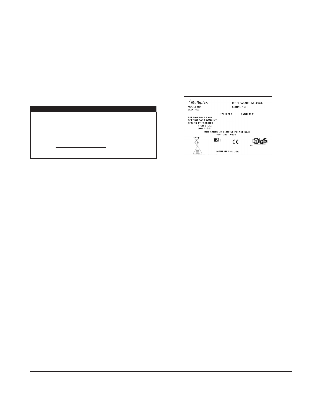
Serial Number Location
The Blend-In-Cup beverage system serial number is listed
on the serial number decal affixed to the middle of the
lower back panel. Another serial number decal is located on
the right side of the machine.
Sample Serial Tag
Part Number 9294938 07/29/2016 9
Page 10
General Information Section 1
D
G
I
F
* H
E
A
C
B
J
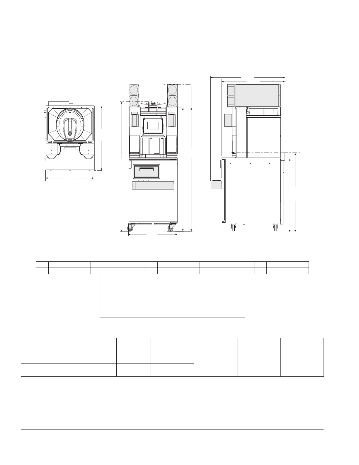
Specifications
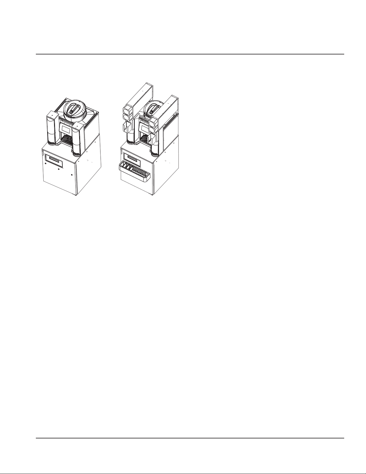
DIMENSIONS
Elevation View Side View
Plan View
NOTE: This illustration covers all
models, grayed out areas are options
that may be on the unit. Dimension
C is the same on all models.
* Low profile casters reduce height by 1.5” (4 cm)
A 71.25" (181 cm) C 26.00" (66 cm) E 60.25" (153 cm) G 33.74" (86 cm) I 36.15" (92 cm)
B 32.82" (83 cm) D 40.10" (102 cm) F 26.00" (66 cm) *H 63.48" (161 cm) J 39.09" (99 cm)
Warning
n
To avoid instability the installation area must be capable
of supporting the weight of the equipment and a full
bin of ice. Additionally the equipment must be level side
to side and front to back.
CAPACITY & WEIGHT
Ice Capacity HP Max Product
Lower Cabinet – 1/5 19.8 lbs
Ice Bin 23 lbs (10 kg) – –
BinLoad
(9 kg)
Shipping
Weight
461 lbs
(209 kg)
Crated
Empty Weight Full Weight
347 lbs
(157 kg)
Unpacked No
Ice/Product
500 lbs
(227 kg)
With Ice/
Product
10 Part Number 9294938 07/29/2016
Page 11
Section 1 General Information
PRODUCT DELIVERY LOCATION
The location selected for the Blend-In-Cup Beverage System
must meet the following criteria.
• The air temperature must be at least 40°F (4°C), but
must not exceed 90°F (32°C), climate class 4.
• The location must not be near heat-generating
equipment or in direct sunlight and must be protected
from weather.
• Plain or Chilled Inlet Water Temperature:
min/max = 40°F / 90°F (4°C / 32°C).
• Always use the water supply line supplied when
installing this appliance. Never reuse an old supply line.
• Verify floor of install location is level front to back, side
to side.
• Keep equipment area clear of combustible material.
Warning
n
Carbon Dioxide (CO2) displaces oxygen. Exposure to a
high concentration of CO2 gas causes tremors, which
are followed rapidly by loss of consciousness and
suffocation. If a CO2 gas leak is suspected, particularly
in a small area, immediately ventilate the area before
repairing the leak. CO2 lines and pumps must not be
installed in an enclosed space. An enclosed space can
be a cooler or small room or closet. This may include
convenience stores with glass door self serve coolers. If
you suspect CO2 may build up in an area, venting of the
B-I-B pumps and / or CO2 monitors must be utilized.
REFRIGERANT CHARGE
Important
Due to continuous improvements, this information is
for reference only. Please refer to the serial number tag
to verify electrical data. Serial tag information overrides
information listed on this page.
R-404a
Lower Cabinet
(Cabinet 1)
12 oz.
(339 g)
Clearances
Top 18" (46 cm)
Sides 0" (0 cm)
Back 6” (15 cm)
Front 30" (76 cm)
Warning
n
Do not obstruct machine vents or openings.
Heat of Rejection
Models Heat of Rejection
BTU/h
R404a Base Cabinet (Cabinet 1) 2100
Part Number 9294938 07/29/2016 11/30/2016 11
Page 12
General Information Section 1
Electrical
Warning
n
All wiring must conform to local, state and national codes.
Minimum Circuit Ampacity
The minimum circuit ampacity is used to help select the
wire size of the electrical supply. (Minimum circuit ampacity
is not the Blend-In-Cup Beverage System’s running amp
load.) The wire size (or gauge) is also dependent upon
location, materials used, length of run, etc., it must be
determined by a qualified electrician.
Electrical Requirements
Refer to Blend-In-Cup Beverage System Model/Serial Plate
for voltage/amperage specifications.
Caution
,
Operate equipment only on the type of electricity
indicated on the specification plate.
Voltage
The standard voltage is 230 VAC-50 Hz. A dedicated
electrical circuit is required, a power cord is provided with
all units.
Some models are available in different voltages and may be
equipped with a different plug, for details on each model
always refer to the serial number tag to verify electrical
data.
Minimum Circuit Amperage Chart
Important
Due to continuous improvements, this information is
for reference only. Please refer to the serial number tag
to verify electrical data. Serial tag information overrides
information listed on this page.
Model Voltage/Cycle/
Phase
MA-8-2 120/60/1 8.6
MA-8-2AF 230-240/50/1
Grounding Instructions
n
The machine must be grounded in accordance with
national and local electrical codes.
This appliance must be grounded. In the event of
malfunction or breakdown, grounding provides a path
of least resistance for electric current to reduce the
Total Amps Breaker Size
5.0
Warning
(Max)
20AMA-8-2BF 220/60/1
risk of electric shock. This appliance is equipped with a
cord having an equipment-grounding conductor and
a grounding plug. The plug must be plugged into an
appropriate outlet that is properly installed and grounded
in accordance with all local codes and ordinances.
Bonding Instructions (230-240V 50 Hz Models Only)
This appliance must be connected to the potential
equalization system in accordance with EN60335-1 and
EN60335-2-75. A bonding lug is provided on the lower right
front corner of the appliance.
Warning
n
This machine must be connected to the potential
equalization system.
Warning
n
When using electric appliances, basic precautions must
always be followed, including the following:
a. Read all the instructions before using the
appliance.
b. To reduce the risk of injury, close supervision
is necessary when an appliance is used near
children.
c. Do not contact moving parts.
d. Only use attachments recommended or sold by
the manufacturer.
e. Do not use outdoors.
f. For a cord-connected appliance, the following
must be included:
• Do not unplug by pulling on cord. To unplug,
grasp the plug, not the cord.
• Unplug from outlet when not in use and
before servicing or cleaning.
• Do not operate any appliance with a
damaged cord or plug, or after the appliance
malfunctions or is dropped or damaged in
any manner. Contact the nearest authorized
service facility for examination, repair, or
electrical or mechanical adjustment.
g. Follow applicable lock out tag out procedures
before working on equipment.
h. Always unplug before replacing the lamp.
Replace the bulb with the same type.
i. Connect to a properly grounded outlet only. See
Grounding Instructions.
12 Part Number 9294938 07/29/2016
Page 13
Section 1 General Information
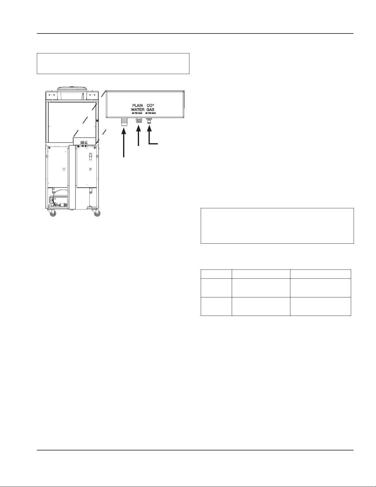
AIR / CO2, PLAIN & CHILLED WATER
Warning
n
Connect to a potable water supply only.
• Use supplied 3/8” (.95 cm) panel-mounted hose barb
and 6’ (1.8 m) of beverage tubing to connect labeled
coupling body fitting(s) on back of unit for each supply
connection.
• Do not connect either water connection to a hot water
supply. Be sure all hot water restrictors installed for
other equipment are working. (Check valves on sink
faucets, dishwashers, etc.)
• Install a water shut-off valve in the water line at the rear
of the machine.
• Insulate water inlet lines to prevent condensation.
Drain
OUT
Plain
Water
IN
Air/CO2
IN
Hard Water
In areas where the water is highly concentrated with
minerals the water should be tested by a water treatment
specialist, and the recommendations of the specialist
regarding filtration and/or treatment should be followed.
SYSTEM PRESSURES
Supply to the Unit
Warning
n
Do not supply more than 80 psi (0.551 MPa , 551 kPa,
5.51 bar) Air/CO2 to the unit, excessive pressure to
product pumps may cause failure.
This table shows the Minimum / Maximum supply of Water and
Air/CO2 required at the rear of the machine at no flow conditions.
MINIMUM MAXIMUM
Air / CO
2
Supply
Plain Water
Supply
(..345 MPa , 345 kPa, 3.45 bar)
(0.448 MPa , 448 kPa, 4.48 bar)
50 psi
65 psi
80 psi
(0.551 MPa , 551 kPa, 5.51 bar)
90 psi
(0.620 MPa, 620 kPa, 6.20 bar)
Part Number 9294938 07/29/2016 11/30/2016 13
Page 14
General Information Section 1
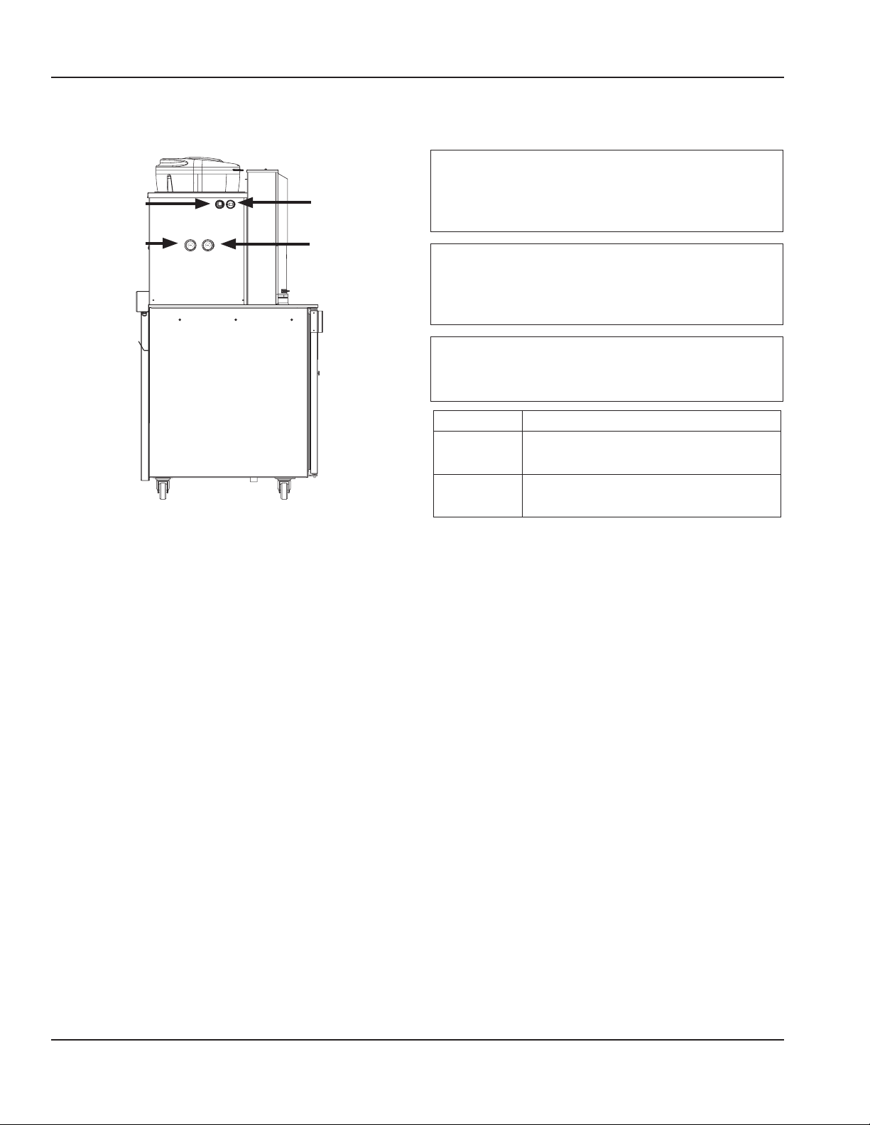
REGULATOR SETTINGS & LOCATION
Regulator Settings
Important
Air/CO2 Requires the pressure measurement to be taken
ON/OFF
Switch
Air/CO2 (Pumps)
Regulator
35 psi (0.24 MPa,
241 kPa, 2.41 bar)
USB Port
Plain Water
Regulator
35 psi (0.24 MPa,
241 kPa, 2.41 bar)
only when a product pump is being activated (product
pump during flow conditions).
Important
Water requires the pressure measurement to be taken
only when rinse water is spraying (flowing conditions)
in a blender chamber.
Important
Water pressure affects the blender area cleaning, a
water booster may be required if pressure is too low.
REGULATOR SETTINGS (During Flowing Conditions)
Pumps
Air / CO
2
Plain Water
(0.24 MPa, 241 kPa, 2.41 bar)
(0.24 MPa, 241 kPa, 2.41 bar)
35 psi
35 psi
DRAIN CONNECTIONS
• Connect supplied 1” ID hose to hose-barb connection
on machine.
• Drain lines must have a 1.5 inch drop per 5 feet of run
(2.5 cm per meter), and must not create traps.
• The floor drain must be large enough to accommodate
drainage from all drains.
• An air gap is included in the design of the machine for
back flow prevention. Plumb to local code.
14 Part Number 9294938 07/29/2016
Page 15
Installation
Step-by-Step Installation
These instructions are provided to assist the qualified
installer. Contact your Manitowoc Foodservice Service
Agent or call Manitowoc Foodservice for information
regarding start-up services.
Important
Failure to follow these installation guidelines may affect
warranty coverage.
Section 2
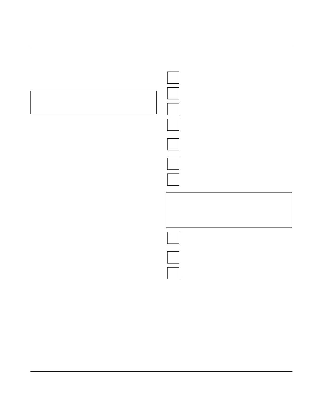
PREINSTALLATION CHECKLIST
Keep product bags in a cooler at least 24 hours
prior to installation.
Any damage should be noted and reported to the
delivering carrier immediately.
Check the lower portion of the unit to be sure
casters are not bent.
Visually inspect the refrigeration package,
compressor compartment housing. Be sure lines
are secure and base is still intact.
Inspect installation location behind the BIC for
electrical outlet location, CO2, water hose fittings,
and shutoff.
Check voltage at outlet dedicated for BIC.
Verify floor of install location is level front to back,
side to side and all casters are touching the floor.
Warning
n
The mass of this appliance will allow it to move
uncontrolled on an inclined surface. Adequate means
must be provided to prevent uncontrolled movement
at all times.
Remove the side panels from the unit to make the
board connections, Air/CO2 and Water Regulator
gauges accessible.
Check that board connections are secure and did
not vibrate loose during shipment.
Check that both micro switches are in line with the
motor above the blenders.
Part Number 9294938 07/29/2016 15
Page 16
Installation Section 2
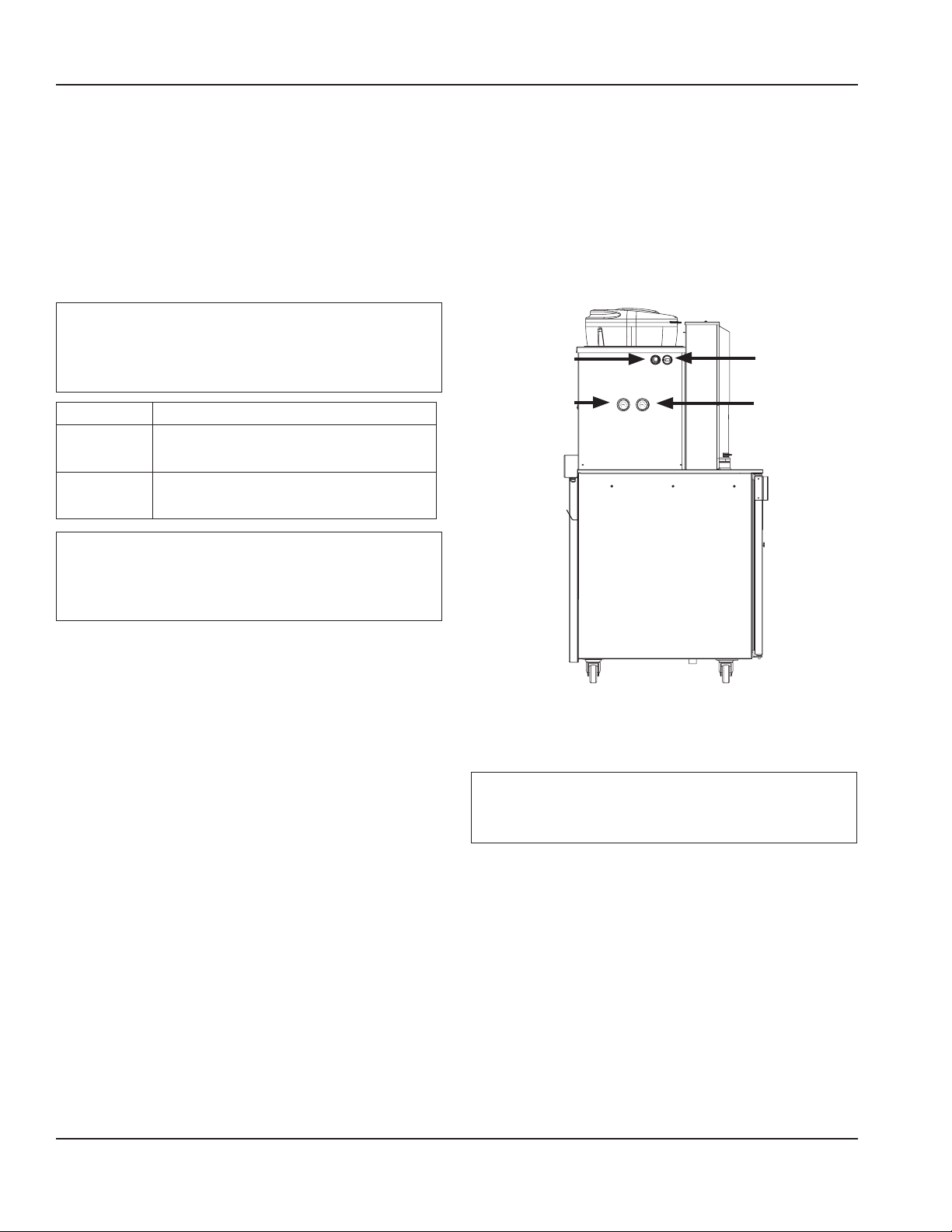
CONNECTIONS
See “System Pressures” on page 13 and “Regulator Settings &
Location” on page 14
1. Confirm correct orientation of Water and Air/CO2
fittings.
2. The line set included with the unit should be equipped
with male quick connect fitting(s) for the water supply
line(s) and female quick connect fitting(s) for the Air/
Electrical
See “Electrical” on page 12
5. If all electrical and grounding requirements have been
followed proceed to insert electrical plug from BIC into
wall receptacle.
6. Turn power switch on the left hand side of the unit to
the ON position.
CO2 supply line
Important
Leave enough slack in the water/CO2/drain lines to allow
access to the rear of the machine without disconnecting
the lines.
REGULATOR SETTINGS (During Flowing Conditions)
Pumps
Air / CO
2
Plain Water
(0.24 MPa, , 241 kPa, 2.41 bar)
(0.24 MPa, 241 kPa, 2.41 bar)
35 psi
35 psi
ON/OFF
Switch
Air/CO2 (Pumps)
Regulator
35 psi (0.24 MPa,
241 kPa, 2.41 bar)
USB Port
Plain Water
Regulator
35 psi (0.24 MPa,
241 kPa, 2.41 bar)
Important
Regulators are factory set but will need to be checked
and possibly adjusted under flowing conditions once
the unit is operational.
See “How to Check Air/CO2 Pressure” on page 64 and “How
to Check Plain Water Pressure” on page 66
3. Coil excess tubing and secure with tie straps.
Drain
See “Drain Connections” on page 14
4. Route drain line (minimum 1” ID) to drain, maintaining
a 2” (51 mm) air gap. Cut to proper length if needed (do
not leave loops in drain).
7. The touch screen should energize and inform the user to
perform Zone 2 & 3 cleaning before the unit can be put
into operation. See “Start-up & Cleaning” on page 17
Important
Do not add product to the machine until cleaning and
sanitizing are complete.
16 Part Number 9294938 07/29/2016
Page 17
Section 2 Installation
STARTUP & CLEANING
Checklist
Review before proceeding with Start-Up & Cleaning.
All internal packing has been removed?
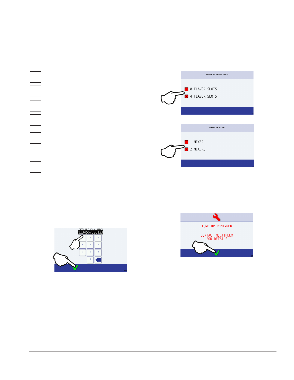
Set Flavors & Mixers
9. Installer must also choose the number of flavors and
mixers to be configured before being granted access to
the user interface.
Have all of the electrical, water and CO2
connections been made?
Is there proper clearance around the machine for
air circulation?
Is the machine grounded / polarity correct?
Has the machine been installed where the
incoming water temperature will remain in the
range of 40°F / 90°F (4°C / 32°C)?
Have the regulators been properly set?
Have the blender door(s) sensor position(s) been
checked?
Has the Power switch been turned to the ON
position?
Serial Number
8. During the first start-up of the machine the installer will
be asked to input the unit’s 13 digit serial number.
A. Enter the serial number.
B. Press the green check to continue.
A
B
NOTE: These can be changed later through the Manager’s
Menu if needed.
Tune-Up Reminder
10. The Tune-Up reminder screen will appear during initial
installation, press the green check to continue.
11. The red wrench at the top of the screen and reminder
will periodically popup until the installation date is set
in the Managers Menu.
NOTE: This will be done once Start-Up and Cleaning have
been completed.
Part Number 9294938 07/29/2016 17
Page 18
Installation Section 2
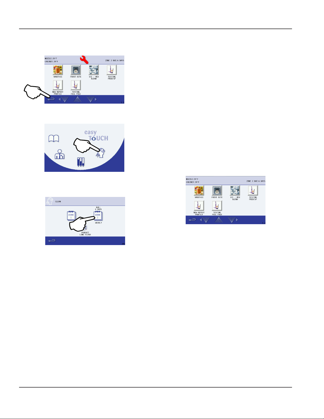
12. Press the Back Arrow in the lower left corner to access
the Main Menu.
13. Select the Cleaning Icon.
14. Select Zone 2, Clean and sanitize the Blend-In-Cup
machine by following the on screen instructions.
NOTE: During the cleaning process is an ideal time to verify
pressure regulator settings during flowing conditions. See
“Regulator Settings & Location” on page 14
D. Ice bin manually filled with ice. See “Manual Fill Ice” on
page 23 .
E. Product bags retrieved from walk-in cooler, installed into
the product bins and placed into their proper location in
the cabinet. See “Procedure to Install a Product Bag” on
page 51 & “Assigning Flavors” on page 40.
F. All product lines primed and ready for use.
Label
15. Add labels to product bins, put labels in correct place.
16. Add labels anywhere else on the unit required.
Software
17. Load recipes. See “Recipe Loading Procedure” on page
45.
18. Verify correct drinks and flavors are available.
NOTE: See “Weekly Cleaning - Zone 2” on page 28. By
doing so, the following will have been completed:
A. All beverage lines, ice bin, dispense area, and blender
chambers, cleaned and sanitized.
B. Water run through the drain to verify it is draining properly.
C. Verify all regulators are set correctly during
cleaning.
(Drink choices will vary depending on loaded recipe file)
Drink Selection Screen
18 Part Number 9294938 07/29/2016
Page 19
Section 2 Installation
Calibrate
See “Calibration Procedure” on page 41
19. Product calibration can be performed once operating
temperature has been reached. Once completed, the
Blend-In-Cup machine is ready for use.
20. Reinstall all side panels.
21. Push the BIC unit into place.
22. Verify the unit is level and shim if necessary.
Demonstrate
23. Demonstrate using the Interface. See “Touch Screens”
on page 31.
24. Demonstrate how to make drink. See “Procedure to
Make a Drink” on page 33.
25. Demonstrate Manager Menu options, using the
default password. (The password can be changed.) See
“Manager’s Menu Screen” on page 35.
26. Set date and time to activate warranty.
27. Complete start-up form, sign, and have store manager
sign form. (Fax to number on form.)
POST INSTALLATION CHECKLIST
Has the machine been properly sanitized?
Has each flavor been installed and primed?
Has ice been added to the bin?
Have the all regulators been correctly set during
flowing conditions?
Is the machine cycling ON/OFF on the temperature
control?
Has the owner/operator been instructed regarding
maintenance procedures?
Has the owner/operator completed the warranty
registration card?
Part Number 9294938 07/29/2016 19
Page 20

Installation Section 2
THIS PAGE INTENTIONALLY LEFT BLANK
20 Part Number 9294938 07/29/2016
Page 21
Section 3
Operation
Sequence of Operation
Dual Blend Chamber
without
Cup Dispenser
Drink Selection screen appears after power-up of the unit.
Operator presses one of the drink type buttons on the Drink
Selection screen, and the Flavor Options screen appears.
Once a flavor is selected, the Size screen appears. See
“Procedure to Make a Drink” on page 33.
Next the drink preparation sequence commences. If add-ins
are required for the drink, the user will be prompted. Here,
according to the drink size selected and when initiated
through the touch screen, the machine dispenses product
and ice into the cup in the dispense area. The cup is then
placed into an available blend chamber.
With the blend chamber door closed and after “Start Mixer”
is selected on the touch screen, the machine blends the
drink for the correct time at the proper blender speed. If
add-ins are required for the drink after blending, the user
will be prompted.
After the drink is removed and the operator closes the
blend chamber door, the automatic rinse of the blender
initiates. The Drink Selection screen re-appears.
Dual Blend Chamber
with Top Mount Cup
Dispenser
Product Dispense Operation
The sequence varies according to the recipe. Some recipes
will use one ingredient, others will use multiple ingredients.
The sequence below uses one ingredient to simplify the
sequence.
Prerequisites:
• Line voltage must be supplied
• CO2 pressure is supplied and regulated to the correct
pressure
• Product is inserted in cabinet and correctly connected
to adapter/tubing
• Ice is available
• Water is supplied at the correct pressure
• A recipe has been developed in MenuConnect and
transferred to the control board with a USB drive.
OPERATION
Selecting a drink from the touch screen will energize the
following components for the time specified by the recipe:
A. The ice dispense wheel turns to add ice.
B. The water inlet valve opens to dispense water.
C. The solenoid valve opens and supplies CO2 to the
product pump.
D. The product pump energizes and pumps the
product into the cup.
The cup is then transferred to a blending station.
Part Number 9294938 07/29/2016 21
Page 22
Operation Section 3
Refrigerated Cabinet Operation
Default temperature set point = 2.2°C / 36° F with a 2.2°C /
4° F Differential.
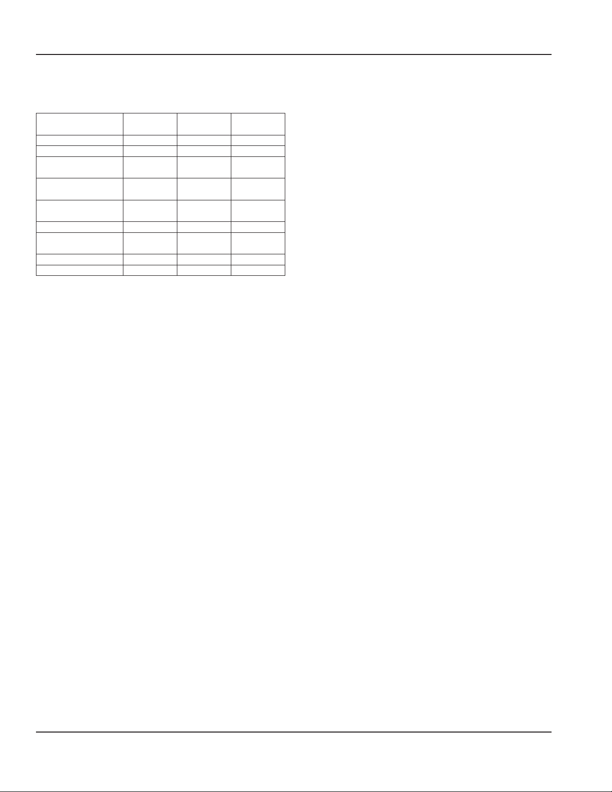
Parameter Default
Setting
Set-point (°F) 36 32 38
Differential (°F) 4 1 6
Minimum Off Time
(Min)
Defrost Run Time
(Min)
Defrost Temperature
(°F)
Defrost Time (Min) 15 10 20
Defrost Initiation
Temperature (°F)
Default On Time (Min) 12 10 20
Default Off Time (Min) 3 2 5
3 2 5
180 120 240
43 35 50
5 0 12
Minimum
Setting
Maximum
Setting
NORMAL OPERATIONS
The microprocessor control board controls the cabinet
temperature based on the input received from the
cabinet temperature thermistor. The thermistor value is
compared to the control board set point. When the reach-in
temperature is equal or greater than the set point (plus half
the differential), the compressor relay closes, provided the
following conditions are satisfied:
• Power has been uninterrupted to the control board for a
3 minute period.
OR
• The 3 minute compressor time delay has expired. The
delay period starts after the compressor has run and
then cycles off.
The compressor relay opens when the reach-in temperature
is less than the set point (minus half the differential).
OPERATION IN THE CLEAN/SANITIZE CYCLE
During the weekly cleaning/sanitize cycle, the evaporator
fan motor relay and the condenser fan motor/compressor
relay remain energized.
ADAPTIVE DEFROST
After 3 hours of cumulative compressor run time, the
compressor will be de-energized for fifteen (15) minutes.
HIGH TEMP ALARM
High temp alarm will display when product thermistor
is above 5.5°C / 42°F for 30 minutes and the following
conditions are satisfied:
• 3 hours since power is applied
• 1 hour since cleaning cycle
Error display will reset when the temperature reaches 5°C /
41°F or below.
THERMISTOR FAILURE
If the microprocessor control board receives an open
or shorted cabinet thermistor signal, the following will
happen:
1. A fault is displayed on the LCD screen
- Cabinet sensor open
Or
- Cabinet sensor shorted
2. The microprocessor will initiate a default sequence for
the refrigeration system - 12 minutes on, 3 minutes off.
3. The default cycle continues until the fault is corrected
or power is disconnected. See “Temperature Thermistor
- Nozzle, Cabinet or Defrost” on page 125.
EVAPORATOR & CONDENSER FAN MOTOR OPERATION
The condenser fan motor and compressor share the
same relay. The evaporator fan motor relay is energized
continuously and the evaporator fan runs continuously.
22 Part Number 9294938 07/29/2016
Page 23
Section 3 Operation
Other Operations
RECOMMENDED CUPS
The following are cup general guidelines. Cups outside
these parameters may work - testing in the machine with
the product will be necessary.
- Cup heights between 4.25" (10.8 cm) and 7.00"
(17.8 cm).
- Cup opening diameter greater than 3.50"
(8.9 cm) and less than 4.18" (10.6 cm).
- Cup base diameter greater than 2.38" (6.0 cm)
and less than 2.62" (6.6 cm).
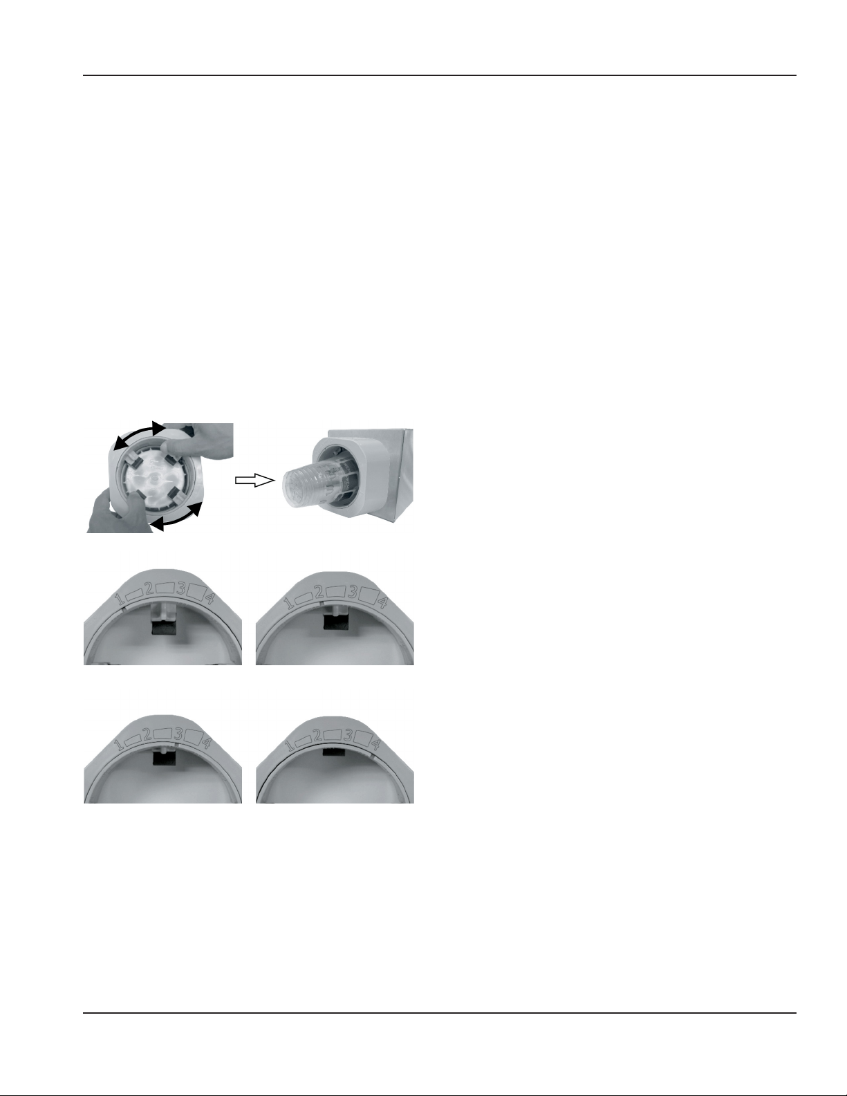
CHANGING THE CUP DISPENSER SIZE
Turn the inner dial so that the notch sets at 1, 2, 3 or 4.
Setting 1 will hold the smallest cup and 4 the largest cup.
When the dial moves from 1 to 2, the dispenser fingers
retract and allow for a larger cup to be inserted.
MANUAL FILL ICE
Procedure to add ice to the Ice bin.
1. Remove lid from ice bin and set aside.
2. Using a clean/sanitized container transfer ice from the
back room ice machine to the ice bin.
3. Pour the ice from the transfer container into the ice bin
until it is full; do not overfill.
4. Replace ice bin lid and verify lid seats in place.
5. The lid must fit in place to activate the ice bin lid switch
Position 1
Position 3
Part Number 9294938 07/29/2016 23
Position 2
Position 4
Page 24

Operation Section 3
THIS PAGE INTENTIONALLY LEFT BLANK
24 Part Number 9294938 07/29/2016
Page 25
General Maintenance
Section 4
Maintenance
This section covers common unit components and their
care. The chart below is an overview of the maintenance
that the end user and service technician should perform,
and the frequency. These figures are the minimum required.
(X = End User, S = Service Company)
DAILY, WEEKLY, MONTHLY
Maintenance Daily Weekly Monthly
Blender / Dispense Area
Cleaning/ Sanitizing
(Zone 1 Cleaning)
Product Line Cleaning &
Sanitizing (Zone 2 Cleaning)
Drain Cleaning X
Clean Condenser Coil
X
X
QUARTERLY & BIANNUAL
Maintenance 3 Months 6 Months
Blender / Dispense Area
Cleaning/ Sanitizing
(Zone 1 Cleaning)
Product Line Cleaning &
Sanitizing
(Zone 2 Cleaning)
Drain Cleaning
Clean Condenser Coil X
ANNUAL, SHUTDOWN & STARTUP
Maintenance Annual After
Prolonged
Shutdown
Blender / Dispense Area
Cleaning/ Sanitizing
(Zone 1 Cleaning)
Product Line Cleaning &
Sanitizing
(Zone 2 Cleaning)
Drain Cleaning X
Clean Condenser Coil X
X S
At Start-
up
Important
If the machine going to be shutdown for any length
of time it is recommended to go through the Zone 2 Weekly Cleaning both prior to turning off the unit and
when returned to use.
If the unit is turned off, the product will no longer be kept
cool in the refrigeration cabinet, remove all product bags
and keep refrigerated to prevent spoilage.
DOOR GASKET MAINTENANCE
Door gaskets require regular cleaning to prevent mold
and mildew buildup and also to retain the elasticity of
the gasket. Gasket cleaning can be done with the use of
warm soapy water. Avoid full strength cleaning products
on gaskets as this can cause them to become brittle and
crack. Never use sharp tools or knives to scrape or clean the
gasket. Gaskets can be easily replaced and do not require
the use of tools or an authorized service person. The gaskets
are “Dart” style and can be pulled out of the groove in the
door and new gaskets can be “pressed” back into place.
DRAIN MAINTENANCE INSIDE LOWER CABINET
Each unit has a drain located inside the unit that removes
the condensation from the evaporator coil and routes it
to an external condensate evaporator pan. Each drain can
become loose or disconnected during normal use. If you
notice water accumulation on the inside of the unit, be sure
the drain tube is connected to the evaporator drain pan. If
water is collecting underneath the unit, make sure the end
of the drain tube is in the condensate evaporator in the
machine compartment. The leveling of the unit is important
as the units are designed to drain properly when level. Be
sure all drain lines are free of obstructions.
Warning
n
Disconnect power to the unit before performing any
service or maintenance functions.
Part Number 9294938 07/29/2016 25
Page 26
Maintenance Section 4
REFRIGERATOR
Caution
Warning
n
Do not damage the refrigeration circuit when installing,
maintaining or servicing the unit.
The interior and exterior can be cleaned using soap and
warm water. If this isn’t sufficient, try ammonia and water
or a nonabrasive liquid cleaner. When cleaning the exterior,
always rub with the “grain” of the stainless steel to avoid
marring the finish. Do not use an abrasive cleaner because
it will scratch the stainless steel and can damage the
breaker strips and gaskets.
STAINLESS STEEL CARE & CLEANING
To prevent discoloration or rust on stainless steel, several
important steps need to be taken. First, we need to
understand the properties of stainless steel. Stainless steel
contains 70-80% iron, which will rust. It also contains 1230% chromium, which forms an invisible passive film over
the steel’s surface, which acts as a shield against corrosion.
As long as the protective layer is intact, the metal is still
stainless. If the film is broken or contaminated, outside
elements can begin to break down the steel and begin to
form discoloration or rust. Proper cleaning of stainless steel
requires soft cloths or plastic scouring pads.
Important
Never Use Steel Pads, Wire Brushes or Scrapers!
Never use a high-pressure water wash for this cleaning
procedure as water can damage the electrical
components located near or at the condenser coil.
DOORS/HINGES
Over time and with heavy use, doors and hinges may
become loose. If this happens, tighten the screws that
mount the hinge brackets to the frame of the unit. Loose or
sagging doors can cause the hinges to pull out of the frame,
which may damage both the doors and the hinges. In some
cases this may require trained & qualified service agents or
maintenance personnel to perform repairs.
NOTE: Do not place hot pans on/against the blue ABS liner.
Do not throw items into the storage area. Failure to follow
these recommendations could result in damage to the
interior of the cabinet or to the blower coil. Overloading
the storage area, restricting the airflow, and continuous
opening and closing of the doors and drawers will hamper
the unit’s ability to maintain operational temperature.
PREVENTING CORROSION
Immediately wipe up all spills.
CLEANING KITS
,
Cleaning solutions need to be alkaline based or nonchloride cleaners. Any cleaner containing chlorides will
damage the protective film of the stainless steel. Chlorides
are also commonly found in hard water, salts, and
household and industrial cleaners. If cleaners containing
chlorides are used, be sure to rinse repeatedly and dry
thoroughly. Routine cleaning of stainless steel can be done
with soap and water. Extreme stains or grease should be
cleaned with a non-abrasive cleaner and plastic scrub pad.
Always rub with the grain of the steel. There are stainless
steel cleaners available which can restore and preserve the
finish of the steel’s protective layer. Early signs of stainless
steel breakdown are small pits and cracks. If this has begun,
clean thoroughly and start to apply stainless steel cleaners
in attempt to restore the passivity of the steel.
Caution
,
Never use an acid based cleaning solution! Many food
products have an acidic content, which can deteriorate
the finish. Be sure to clean the stainless steel surfaces of
ALL food products. Common items include: tomatoes,
peppers and other vegetables.
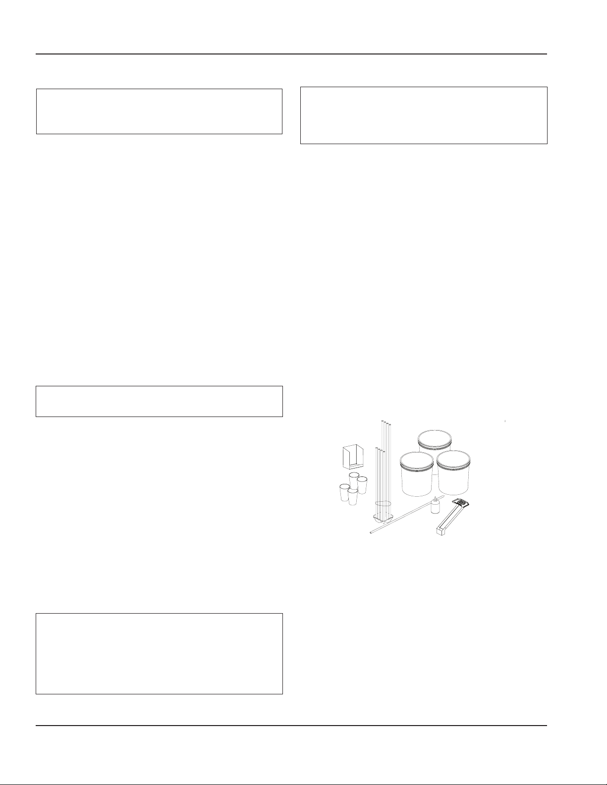
Complete cleaning kits are available (part number 000-BIC001Q). These kits include the following:
• (3) three 5 gallon buckets
• Bucket labels for Wash, Rinse, & Sanitizing
• Red & Blue Cups for blender cleaning
• Squeeze Bottle
• Dispense Area Shield
• Tubing Manifold for product line cleaning
26 Part Number 9294938 07/29/2016
Page 27

Section 4 Maintenance
OTHER MONTHLY TASKS
Cleaning the Condenser Coil
In order to maintain proper refrigeration performance, the
condenser fins must be cleaned of dust, dirt and grease
regularly. It is recommended that this be done at least every
three months. If conditions are such that the condenser is
totally blocked in three months, the frequency of cleaning
should be increased. Clean the condenser with a vacuum
cleaner or stiff brush. If extremely dirty, a commercially
available condenser cleaner may be required.
Failure to maintain a clean condenser coil can initially cause
high temperatures and excessive run times. Continuous
operation with a dirty or clogged condenser coil can
result in compressor failure. Neglecting the condenser coil
cleaning procedures will void any warranties associated
with the compressor and cost to replace the compressor.
Caution
,
Never use a high-pressure water wash for this cleaning
procedure as water can damage the electrical
components located near or at the condenser coil.
Part Number 9294938 07/29/2016 27
Page 28
Maintenance Section 4
Daily Cleaning - Zone 1
Zone 1 cleaning is accessed through the cleaning icon on
the touch screen. It covers the basic components of the BIC
that will need cleaned on a daily basis.
NOTE: The on-screen instructions can vary depending
on the recipe that was created with the MenuConnect
program. All Zone 1 cleaning steps are covered in the
Installation Operation & Maintenance manual that ships
with the unit.
• Time to complete - 15 minutes
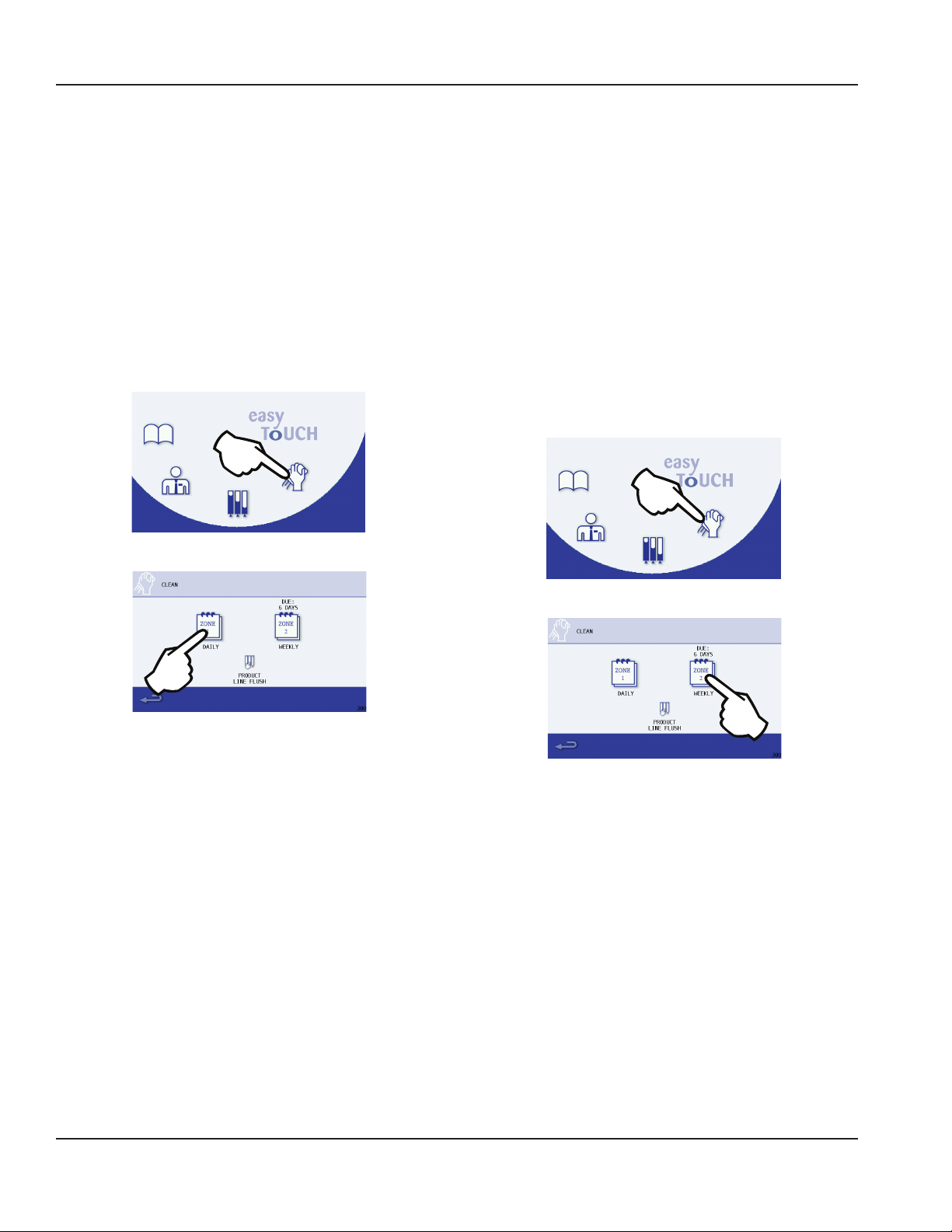
1. Cycle touch screen to the Main Menu and select the
Cleaning icon.
2. In the Cleaning screen select the ZONE 1 icon.
Weekly Cleaning - Zone 2
Zone 2 cleaning is accessed through the cleaning icon on
the touch screen. It covers all the steps that will need to be
performed to complete the weekly cleaning.
NOTE: The on-screen instructions can vary depending
on the recipe that was created with the MenuConnect
program or options chosen in the Managers Menu. All Zone
2 cleaning steps are covered in the Installation Operation &
Maintenance manual that ships with the unit.
• Time to complete - 90 Minutes
NOTE: An additional 1 hour 45 minutes will be needed if the
Sanitizing Ice bin option is enabled in the Managers Menu.
1. Cycle touch screen to the Main Menu and select the
Cleaning icon.
Exterior Cleaning
Remove dust and dirt from the exterior surfaces with a mild
household dish washing detergent and warm water. Wipe
dry with a clean, soft cloth.
Use cleaners designed for use with stainless steel products.
Heavy stains should be removed with stainless steel wool.
Never use plain steel wool or abrasive pads. They will
scratch the panels.
Plastic exterior panels and UI (User Interface) Screen should
be cleaned with a mild household dish washing detergent
and warm water on a damp cloth. Wipe dry with a clean,
soft cloth.
2. In the Cleaning screen select the ZONE 2 icon.
NOTE: Failure to complete the weekly cleaning sequence
entirely will not reset the weekly cleaning timer and will
require the process to be repeated.
28 Part Number 9294938 07/29/2016
Page 29
Section 4 Maintenance
Product Line Flush
The Product Line Flush procedure allows a user to choose
which lines to flush instead of being forced to flush every
product line in the unit.
Product Line Flush is accessed through the cleaning icon on
the touch screen. It covers all the steps that will need to be
performed to complete Product Line Flushing.
NOTE: The on-screen instructions can vary depending on
the recipe that was created with the MenuConnect program
or options chosen in the Managers Menu. All Product Line
Flush steps are covered in the Installation Operation &
Maintenance manual that ships with the unit.
1. Cycle touch screen to the Main Menu and select the
Cleaning icon.
Annual Planned Maintenance
The following parts are recommended for annual planned
maintenance replacement to ensure optimum unit
performance and minimize downtime:
• Refrigerator door gasket (cleaning may be sufficient)
• Two (2) #6 O-rings for the water and CO2/air quick
connect lines
• Nine (9) LMS valves
• (1 Or 2) Mixer assemblies
• Ice Dispense Wheel
• Blender Shaft Assemblies
NOTE: All planned maintenance must be done by an
approved, certified Manitowoc Field Service Technician.
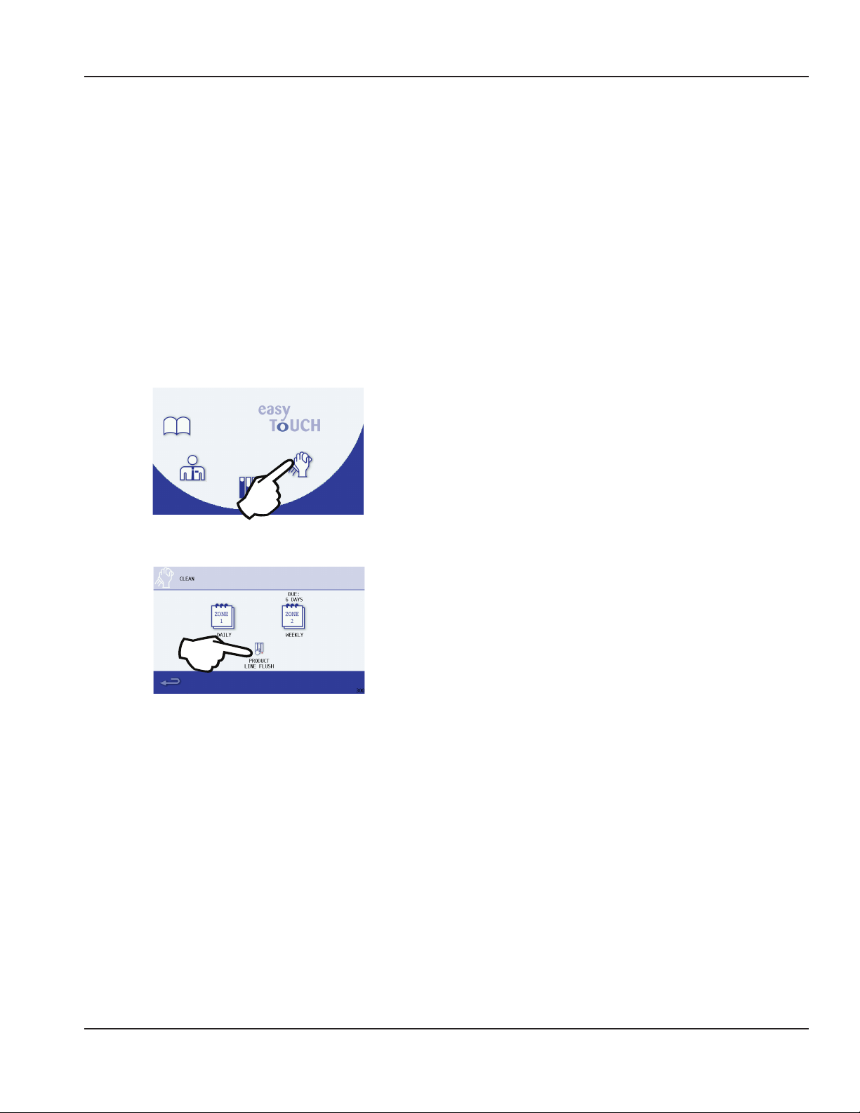
2. In the Cleaning screen select the PRODUCT LINE FLUSH icon.
NOTE: Performing the product line flush through this
interface procedure will not reset the Zone 2 cleaning
countdown timer, Zone 2 cleaning will need to be
performed in its entirety in order to reset the counter.
Part Number 9294938 07/29/2016 29
Page 30

Maintenance Section 4
THIS PAGE INTENTIONALLY LEFT BLANK
30 Part Number 9294938 07/29/2016
Page 31

Section 5
Controls
Touch Screens
The “easy ToUCH” screen has four selections. One is for
the drink making procedure: Drink Selection displays by
default at start-up. The Manager’s Menu is for accessing the
machine’s settings. Inventory is for product information and
Cleaning is for routine maintenance of the machine.
Drink
Selection
Managers
Menu
Main Menu Screen
Drink Selection
See “Drink Selection Screen”
See “Flavor Selection Screen” on page 32.
See “Size Screen” on page 32.
See “Main Menu Screen” on page 34.
Manager’s Menu
See “Main Menu Screen” on page 34.
See “Manager’s Menu Screen” on page 35.
Inventory
See “Main Menu Screen” on page 34.
See “Product Inventory Screen” on page 50.
Cleaning
See “Main Menu Screen” on page 34.
See “Cleaning Screen” on page 52.
Inventory
Cleaning
DRINK SELECTION SCREEN
The Drink Selection screen appears on power-up (except
where clean/sanitize limitations have been exceeded, in
which case the Cleaning screen appears). See Maintenance
for Daily and Weekly cleaning/sanitization. This screen’s
primary function is to select a drink to make or access the
Main Menu.
Nozzle &
Cabinet
Temperature
Drink
Categories
Go to Main
Menu Screen
Cleaning
Reminders
Ice Chute
Rinse
Button
Rinse
Button(s)
How to Access
The Drink Selection screen displays by default unless
cleaning is required. This screen can also be accessed
through the Main Menu Book Icon.
Icon Button Descriptions
• NOZZLE & CABINET Temperatures
Displays the current temperature for dispense point nozzle
and the refrigeration cabinet. Unit of measure can be changed
in the Manager’s Menu.
• Drink Categories
The main product categories are displayed left to right
on the Drink Selection screen. Touching a category
will display the drink flavor options available for the
category.
NOTE: Available drink selections may vary depending on
the recipe file installed.
• Main Menu Arrow
Navigates to the Main Menu screen.
• Cleaning Reminders
Displays the time remaining in days until ZONE 2
(Weekly) and ZONE 3* (Monthly) cleaning is required. *If
equipped with this feature.
• Rinse Button
Press to rinse the left or right blender chambers. Blend
chamber door(s) must be closed.
• Ice Chute Rinse Button
Press this button to rinse the ice chute if it becomes
clogged. Repeat if necessary.
Part Number 9294938 07/29/2016 31
Page 32

Controls Section 5
FLAVOR SELECTION SCREEN
The Flavor Selection screen appears after a Drink Selection
has been made. Flavor options will vary depending on what
recipes are configured on the unit. This screen’s primary
function is to select a drink flavor.
Nozzle &
Cabinet
Temperature
Drink
Categories
Go to Main
Menu Screen
Cleaning
Reminders
Ice Chute
Rinse
Button
Rinse
Button(s)
How to Access
The Flavor Selection screen displays after a drink selection
has been made from the Drink Selection screen.
Icon Button Descriptions
• NOZZLE & CABINET Temperatures
Displays the current temperature for dispense point
nozzle and the refrigeration cabinet. Unit of measure
can be changed in the Manager’s Menu.
• Drink Flavor Buttons
Flavor choices for the drink type that was selected.
- Yellow Border
If any of the drink ingredients will expire soon, the
yogurt has expired, or there is less than 10% left in the
product bag. Check the Product Inventory Screen for
exact amount of product remaining.
- Red Border
Product expired or product bag empty, flavor selection
unavailable. Will need to replace product bag.
NOTE: Available flavor selections may vary depending on
the recipe file installed.
• Back Arrow
Navigates to previous Drink Selection screen.
• Cleaning Reminders
Displays the time remaining in days until ZONE 2
(Weekly) and ZONE 3* (Monthly) cleaning is required. *If
equipped with this feature.
• Rinse Button
Press to rinse the left or right blender chambers. Blend
chamber door(s) must be closed.
• Ice Chute Rinse Button
Press this button to rinse the ice chute if it becomes
clogged. Repeat if necessary
SIZE SCREEN
The Size screen appears after a drink flavor has been chosen
from the Flavor Selection Screen. This screen’s primary function
is to select size and make a drink. Optional Add-Ins are also
performed through this screen if the drink requires them.
Nozzle &
Cabinet
Temperature
Add-in
Topping
(If Required)
Go Back
One Screen
Cleaning
Reminders
Drink Size
Selection
Buttons
How to Access
The Size Selection screen displays after a flavor selection
has been made from the Flavor Selection screen.
Icon Button Descriptions
• NOZZLE & CABINET Temperatures
Displays the current temperature for dispense point
nozzle and the refrigeration cabinet. Unit of measure
can be changed in the Manager’s Menu.
• Add-Ins
These are not functioning buttons, only a graphic
representation of the add-in used when making the
selected drink. The screen will prompt the user when
the add-in is to be added to the drink.
NOTE: Not all drinks have an add-in. Drink add-ins may vary
depending on the recipe file installed.
• Drink Size Buttons
Press a drink size (SMALL, MEDIUM, or LARGE) to start
the drink making process.
NOTE: Make sure the correct cup is in place before pressing
the drink size button, once one is selected the unit will
start dispensing product and the screen will display
“DISPENSING“.
The screen will prompt to place cup in mixer when
dispensing is complete and return to the Drink Selection
screen while blending the drink. (See “Procedure to Make a
Drink” on page 33)
• Back Arrow
Navigates to previous Flavor Selection screen.
• Cleaning Reminders
Displays the time remaining in days until ZONE 2
(Weekly) and ZONE 3* (Monthly) cleaning is required. *If
equipped with this feature.
32 Part Number 9294938 07/29/2016
Page 33

Section 5 Controls
Procedure to Make a Drink
NOTE: Ice must be present in the ice hopper, product must be connected and primed to produce a drink.
1. Press the Open Book icon.
2. Select a category of drink recipes.
3. Specific drink combinations are displayed on the next
screen. If a drink is not available, it will be highlighted
with a red square around it. Unavailable flavors have
expired and will need to be replaced. (See “Procedure to
Install a Product Bag” on page 32)
4. Drink size is the next selection.
5. Place cup under center dispenser and press the
corresponding drink size (SMALL, MEDIUM, or LARGE)
to start the drink making process.
6. As the flavor dispenses into the cup, the screen will
display DISPENSING.
7. If Add-in ingredients need to be manually added, the
screen will give specific directions. More ingredients
may be required later, follow the screen directions.
8. The screen will prompt you to use an available mixer,
place the cup into the blender chamber, and shut the
door. Press the corresponding right or left flashing
green/blue arrow to mix the drink.
NOTE: Single mixer unit will only display a right arrow. Press
the red X to cancel.
Part Number 9294938 07/29/2016 33
Page 34

Controls Section 5
9. While the drink is mixing, the top of the screen will read
BLENDING
Drink Status
NOTE: On dual mixer units, a second drink can be selected
and blended simultaneously.
10. Follow all drink specific screen directions for add-ins if
necessary and press the flashing arrow if prompted.
Add-In
Notification
11. When the blender is done mixing, open the door and
remove the drink. The blending station will go through
a rinse cycle after the door is closed again.
NOTE: The blend station will not be available again until the
door is closed and the rinse cycle is completed.
MAIN MENU SCREEN
Accessed primarily though the Drink Selection screen, this
screen’s primary function is to provide access to all other
procedures and adjustments that can be performed on the
unit.
Drink
Selection
Managers
Menu
Inventory
Cleaning
How to Access
Normally accessed through the return arrow in the bottom
left of the Drink Selection screen.
Category Icon Descriptions
• Drink Recipes Menu
Displays the Drink Selection screen.
• Managers Menu
Displays a Password Keypad screen. When password is
correctly entered, a menu of protected information for a
manager will display.
• Inventory
Displays the remaining percentage of product in each
bag, and NOZZLE and CABINET temperature readings.
• Cleaning
Displays the Cleaning screen and gives the options
for ZONE 1 (Daily), ZONE 2 (Weekly) cleaning, and
PRODUCT LINE FLUSH.
34 Part Number 9294938 07/29/2016
Page 35

Section 5 Controls
MANAGER’S MENU SCREEN
Accessed though the Main Menu screen, this screen’s
primary function is to provide on-screen access to Manageronly functions.
How to Access
After selecting Manager’s Menu icon from the Main Menu,
the password screen appears. The manager screens are
password protected. (Default Password is “A”.) Enter the
Manager’s pass code using the QWERTY keypad, then press
the green check to accept.
Password
Display
Area
Clear
Password
Display
Manager Menu Features
• Manager Screen 1
Main Menu Next Screen
- LANGUAGE
(“Changing the UI Language” on page 36)
- DATE & TIME Settings
(“Date & Time Setting” on page 37)
- TEMPERATURE
(“Temperature Setting” on page 38)
- EDIT PASSWORD
(“Edit Password Setting” on page 38)
- CONFIGURE SLOTS
(“Configure Slots Setting” on page 39)
• Manager Screen 2
Password
Input
Keypad
Accept
Password
Cancel
After typing in the correct password, Language, Date/Time,
Temperatures, Edit Password, Configure Slots, Updates,
Auto Wash Timer and Service screens are accessible. When
the manager screens are inactive for a time period, the
screen will return to the drink menu.
Important
Do not change the language, edit the password or
configure the slots unless instructed to do so by the
factory.
Main Menu
Previous
Screen
Next Screen
- UPDATES (“Updates” on page 43)
- AUTO WASH TIMER
(“Auto Wash Timers” on page 47)
- SERVICE (“Service Screens” on page 47)
Part Number 9294938 07/29/2016 35
Page 36

Controls Section 5
• Manager Screen 3
Previous
Screen
Main Menu Next Screen
This screen displays all current software versions on the
unit. (See “Software Version Screen” on page 49.)
• Manager Screen 4
Main Menu
Previous
Screen
Changing the UI Language
Important
Do not change the language unless instructed to do so
by the factory.
These steps are to be followed once the user has gained
access to the Manager’s Menu by entering the correct
password (Default Password is “A”).
1. Select the LANGUAGE icon from the first Manager’s
Menu screen.
This screen displays the Mixer/Blend Cycle counter. Count is
not incremented for non-blended drinks.
(See “Drink Counter Screen” on page 49.)
Previous
Screen
2. Select a language. A green check box indicates what
language is currently selected.
NOTE: Up to four (4) languages may be available, including
English. Available languages are controlled by the recipe file
and are configured in MenuConnect.
3. Press the return arrow in the lower left corner to save
and return to the first Manager’s Menu screen.
4. Press the return arrow again to return to the Main
Menu.
36 Part Number 9294938 07/29/2016
Page 37

Section 5 Controls
Date & Time Setting
Important
Set the correct date and time at installation. Correct the
date or time when necessary.
These steps are to be followed once the user has gained
access to the Manager’s Menu by entering the correct
password (Default Password is “A”).
1. Select the DATE/TIME icon from the first Manager’s
Menu screen.
Touch
to Enter
Date
Time of
Day
Date
Format
Return/
Save
12 hr format
(AM or PM)
24 hr format
Day of the
Week
3. If changes were made, the following screen will display:
- Press SAVE to save the new settings.
- Press DISCARD to cancel any changes.
- The Manager’s Menu will appear after a
selection has been made.
4. Press the return arrow again to return to the Main
Menu.
- Choose the date format that will be used on the
machine: MM-DD-YY.
- To enter the Month, Day, Year, Hours, or Minutes,
touch the corresponding box, type in the
correct number, and press the green check to
accept.
- If using 12 hr time format, select AM or PM. If
using 24 hr format select the 24 check box.
- Only select the Installation check box if this will
be the installation date/time.
2. Select the return/save arrow when done.
Part Number 9294938 07/29/2016 37
Page 38

Controls Section 5
Temperature Setting
These steps are to be followed once the user has gained
access to the Manager’s Menu by entering the correct
password (Default Password is “A”).
1. Select the TEMPERATURES icon from the first Manager’s
Menu screen.
Current Unit
Change
Unit of
Measure
Temperatures
Edit Password Setting
Important
Only a trained manager or authorized technician should
change the default password. Be sure to keep record of
the new password.
These steps are to be followed once the user has gained
access to the Manager’s Menu by entering the correct
password (Default Password is “A”).
1. Select the EDIT PASSWORD icon from the first
Manager’s Menu screen.
Return/
Save
- The screen will display the current NOZZLE,
CABINET, and DEFROST temperature readings.
- To change to Celsius/Metric Units of measure,
press the check box next to SHOW METRIC
UNITS. A green check box means Metric has
been selected.
- Press the return arrow to return to the previous
screen.
- Choose which password to change, MANAGER,
SERVICE, DEMO, or SELF-SERVE.
NOTE: If changing all passwords, they each have to be
selected and changed one at a time.
38 Part Number 9294938 07/29/2016
Page 39

Section 5 Controls
2. Enter the current password. “A” is the factory default for
the “Manager” and/or “Service” password(s). “DEMO” is
the factory default for Demo selection and “SELF” is the
factory default for self-serve selection.
A
- Press the green check to continue.
3. Enter the new password, anything from 1-20 characters.
• Press the green check to continue.
4. Confirm the new password by entering it again.
- Press the green check to confirm and finish
changing the password.
5. The Edit Password Screen will appear.
Configure Slots Setting
These steps are to be followed once the user has gained
access to the Manager’s Menu by entering the correct
password (Default Password is “A”).
Select the Configure Slots icon from the first Manager’s
Menu screen. There are two sub-menus, SLOT FLAVOR and
CALIBRATE FLAVOR.
6. Press the return arrow twice to go back to the Main
Menu.
- The SLOT FLAVOR icon is used to assign flavors
to each product slot on the machine.
- See “Assigning Flavors” on page 40.
- The CALIBRATE FLAVOR icon is used for
calibration of each assigned flavor. Calibrate
Flavor is a process to ensure the machine is
dispensing the correct amount from each
product slot, water and ice. See “Calibration
Procedure” on page 41.
Part Number 9294938 07/29/2016 39
Page 40

Controls Section 5
Assigning Flavors
1. Press the SLOT FLAVOR icon.
2. Select a slot you want to assign a flavor to.
4. Continue to select slots and flavors until all slots are
assigned.
5. Select the red X when finished to return to the
Configure Slots screen. Select the return arrow twice to
return to the Main Menu.
3. Select from available flavors.
NOTE: Available flavors will vary depending on the recipe
file that is loaded on the machine. Select ASSIGN FLAVOR.
- Screen will return to the Slot Selection screen.
- The flavor name will now display and the slot
will be highlighted green.
40 Part Number 9294938 07/29/2016
Page 41

Section 5 Controls
Calibration Procedure
Important : Pre-calibration Checklist
If calibrating ice, go to the Drink Menu and
dispense 4 large cups of ice prior to calibrating.
Check for empty product bags in the cabinet and
replace if necessary.
Ensure that each flavor has a bag more than 1/3 full.
Check bag to ensure the spout is securely locked in
position and the spout side of bag is facing down.
Ensure product flavors to be calibrated have been
refrigerated for 24 hours in a 34°F/1°C – 40°F/4°C
environment and the product cabinet is at
operating temperature 32°F/0°C – 34°F/1°C.
Check Zone 2 cleaning was completed over 1 hour ago.
Check CO2/air pressure. If CO2/Air pressure has
changed, reset pressure to required level.
Check that Machine has been turned on for at least
1 hour – Do not proceed with this check during
peak time - Dispense 2 large cups of ice.
1. From the Main Menu, select the Manager icon.
2. Enter the manager’s password.
3. Select CONFIGURE SLOTS.
4. Select CALIBRATE FLAVOR.
Gather the following supplies
Digital Scale
Empty & Clean Cups
NOTE: Except for Water and Ice, a flavor must first be assigned
and product bag loaded before a slot can be calibrated.
5. Select a flavor, water or ice to calibrate.
Selectable Flavors will have a drop shadow
NOTE: If a flavor cannot be selected the bag loading
procedure must first be performed (See “Procedure to Install
a Product Bag” on page 51).
Part Number 9294938 07/29/2016 41
Page 42

Controls Section 5
6. Follow the on-screen instructions and do the following:
• Get a digital scale.
• Tare empty cup weight.
• Position an empty cup for dispense.
• Press Green Check when ready.
A. Wait until dispensing is done.
B. Weigh cup.
C. Flavor and water target is 4 oz. (113 grams) +/-
10%. Ice target is 6 oz. (170 grams) +/- 10%.
D. If weight is not within range, tap button to enter
weight and continue to step 7.
E. If weight is within range press the red X to exit and
choose another flavor, water or ice to calibrate if needed.
8. The calibration screen will display again with the
weight entered on the previous screen.
A. If the weight displayed is incorrect, press the
button again and re-enter weight.
B
A
B. Press Green Check when done to save and
complete calibration for the slot.
9. The CALIBRATION COMPLETE screen will display.
7. The Enter Weight screen will appear.
A. Enter the cup weight using the number pad.
A
B
B. Select the Green Check when done to continue.
NOTE: If the weight entered was not 4 oz. (113 grams)
for a flavor/water or 6 oz. (170 grams) for ice, the unit will
electronically adjust the dispense calibration based on the
weight entered to obtain the correct target dispense weight.
No mechanical adjustments are required.
• Press Green Check to return to the Calibration Slot
Choice screen.
10. The newly calibrated slot will be highlighted in green.
A
B
11. Repeat steps 5 - 6 to verify weight is within range.
12. Once weight is within range;
A. Choose another flavor, water or ice to calibrate.
B. Or press the Back Arrow to return to the
CONFIGURE SLOTS Screen. From there press the
back arrow twice to reach the Main Menu and
place the unit into operation.
42 Part Number 9294938 07/29/2016
Page 43

Section 5 Controls
UPDATES
Firmware and Recipes Screens allow the manager to plug a
USB flash drive in and upload new firmware and recipes.
Important
Only a trained manager or authorized technician should
perform USB updates. If updates are not performed
properly, they can cause the unit to malfunction or not
work at all.
These steps are to be followed once the user has gained
access to the Manager’s Menu by entering the correct
password (Default Password is “A”).
- The FIRMWARE icon is used to update the “easy
ToUCH” user interface, Dispenser, and/or the
Mixers firmware on the machine.
See “Firmware Update Procedure” on page 44
.
- The RECIPES icon is used to update or backup
the available drink flavors and combinations to
or from a USB stick.
See “Recipe Loading Procedure” on page 45.
- The CONFIGURATION icon is used for copying
a unit’s configuration settings to USB or
uploading a previously saved configuration to
the unit from USB.
1. Press the down arrow.
• Press the UPDATES icon.
2. There are four (4) submenus, FIRMWARE, RECIPES,
CONFIGURATION, and SAVE LOGS TO USB.
- The SAVE LOGS TO USB icon is used for copying
all EVENT and/or ERROR logs to a USB stick.
Part Number 9294938 07/29/2016 43
Page 44

Controls Section 5
Firmware Update Procedure
Important
3. Press the down arrow.
1. Read instructions completely.
2. Firmware file must be loaded on top level of flash
drive:
- .BIN for UI updates
- .SRB for Dispenser (SRB) updates
- .MXB for Mixer updates
3. Require only 1 firmware file on the flash drive at a time.
If multiple firmware files are on the flash drive, choose
the correct one when prompted on the screen.
4. Flash drive must be formatted to FAT or FAT32 file
4. Press the UPDATES icon.
format. (Typical for smaller flash drives <2GB.)
1. Plug in the properly formatted flash drive containing
the firmware bin file. The USB port is located on the lefthand side of the unit to the right of the power switch.
USB Ports
Power Switch
2. From the Main Menu, press the Manager’s icon and
enter the password (Default password is “A”).
A
- Press the green check.
5. Press the FIRMWARE icon.
6. Choose which firmware is being updated, USER
INTERFACE, DISPENSER, or MIXERS.
44 Part Number 9294938 07/29/2016
Page 45

Section 5 Controls
7. Verify version to be loaded is correct.
- Press the green check to begin loading new
firmware.
Important
The transfer can take between 10 and 15 minutes to
complete. DO NOT remove the USB flash drive!
8. Firmware will show status of update as a percentage,
and screen will display “STATUS COMPLETE” when
finished.
9. At the Status Complete screen, select the return icon
two or three times to go back to the Main Menu screen.
Recipe Loading Procedure
Important
1. Read instructions completely.
2. Recipe file (.cbr) must be loaded on top level of flash
drive.
3. Require only 1 recipe (.cbr) file on the flash drive at a
time. If multiple firmware (.cbr) files are on the flash
drive, the first one in alphabetical order would be
loaded and may not be the correct version.
4. Flash drive must be formatted to FAT or FAT32 file
format. (Typical for smaller flash drives <2GB.)
1. Plug in the properly formatted flash drive containing
the firmware bin file. The USB port is located on the lefthand side of the unit to the right of the power switch.
USB Ports
Power Switch
Important
You must CYCLE POWER to the unit after an update
before it will take effect.
10. Leaving the USB in place, cycle the power,
A. Turn OFF the power switch.
B. Wait at least 30 seconds.
C. Turn ON the power switch.
11. It is now safe to remove the USB flash drive. Installation
is now complete. Press the return icon to go back to the
Main Menu.
2. From the Main Menu, press the Manager’s icon and
enter the password (Default password is “A”).
A
- Press the green check.
Part Number 9294938 07/29/2016 45
Page 46

Controls Section 5
3. Press the down arrow.
4. Press the UPDATES icon.
5. Press the RECIPES icon.
7. Verify version to be loaded is correct.
- Press the green check to begin loading recipe file.
8. Recipe will show status of update as a percentage, and
screen will display “STATUS COMPLETE” when finished.
9. At the Status Complete screen, select the return icon
two or three times to go back to the Main Menu screen.
Important
You must CYCLE POWER to the unit after an update
before it will take effect.
10. Leaving the USB in place, cycle the power,
A. Turn OFF the power switch.
6. Press UPDATE RECIPES FROM USB.
B. Wait at least 30 seconds.
C. Turn ON the power switch.
11. It is now safe to remove the USB flash drive. Installation
is now complete. Press the return icon to go back to the
Main Menu.
46 Part Number 9294938 07/29/2016
Page 47

Section 5 Controls
Auto Wash Timers
Allows the manager to turn ON / OFF, and set up periodic
automatic wash cycles for the blender stations. Up to six (6)
timers can be set.
These steps are to be followed once the user has gained
access to the Manager’s Menu by entering the correct
password (Default Password is “A”).
1. Press the down arrow.
Service Screens
Allows the manager and qualified service technician access
to optional functions, settings, input, and output readings
used in both setup and diagnostics.
Important
Only a trained manager or authorized technician
should access the service screens. If changes to these
settings are made incorrectly they can cause the unit to
malfunction or not work at all.
These steps are to be followed once the user has gained
access to the Manager’s Menu by entering the correct
password (Default Password is “A”).
- Press the AUTO WASH TIMER icon.
2. By default no timers are preset.
ON/OFF
Time
(24Hr
Format)
Return/
Save
Daily ON/
OFF
Clear Time
Delay if in
Use
3. To save any changes, press the return arrow and return
to the Manager’s Menu. When exiting the Manager’s
Menu, all changes will be confirmed.
1. Press the down arrow.
- Press the SERVICE icon.
2. The service screens are password protected. Enter the
service password (default password is “A”).
A
- Press the green check.
3.
Part Number 9294938 07/29/2016 47
Page 48

Controls Section 5
4. The following choices will be made available;
- OPTIONS
Turn ON/OFF the following; Mixer Rinse, Water
Saving Rinse, Left Mixer, Right Mixer, Condenser
Filter(s).
- CLEANING OPTIONS
Set Zone 2 and 3 timer durations. Enable
sanitizing in Zone 2 cleaning. Enable Descaling
in Zone 3 cleaning.
- OUTPUTS
Displays current state of all drink component
outputs and can be toggled ON/OFF from this
screen.
- CLEANING OUTPUTS
Displays current state of all cleaning component
outputs and can be toggled ON/OFF from this
screen.
- INPUTS
Displays current state of all input components.
- CALIBRATION
Displays current state of all calibration settings.
- Press the down arrow for more choices.
5. The second screen displays more service choices:
- LOCKOUT OPERATIONS
DEMO mode will password protect all icons
once the user saves settings and returns to
the Main Menu. Enter “DEMO” in the password
screen to gain temporary access to the Drink,
Inventory, and Cleaning screens. “A” is the
default password for the Manager’s Menu.
SELF-SERVE mode will limit the user to just drink
making screens and password protect the Main
Menu. Enter “SELF” in the password screen to
gain temporary access to the Main Menu. “A” is
the default password for the Manager’s Menu.
- CABINET SETTINGS
Displays all current cabinet settings. Touch a
setting to change its value.
- FACTORY RESET
Resets all calibrations to factory settings.
Caution
,
This will erase all settings that have been set manually.
- SCREEN CALIBRATION
Calibrates the touch screen sensitivity.
- BOARD REPLACEMENT
Used when a UI or Mixer board is being
replaced.
- Press the down arrow for more choices.
6. The third screen displays more service choices:
- UPDATE UNIT SERIAL NUMBER
Used to input the unit serial number post
installation.
- CONFIGURE YOGURT SMALL DISPENSE
- PLANNED MAINTENANCE
Password protected screen only meant for the
service technician performing the planned
maintenance.
48 Part Number 9294938 07/29/2016
Displays the yogurt small dispense settings, and
can be adjusted from this screen.
- DISPLAY LOGS
Allows the user to display and/or clear all ERROR
and EVENT logs on scree.
- ICE MAKER SETTINGS
Displays all ice maker settings and can be
adjusted from this screen.
Page 49

Section 5 Controls
Software Version Screen
Allows the manager and qualified service technician to see
on screen what software versions are currently installed.
These steps are to be followed once the user has gained
access to the Manager’s Menu by entering the correct
password (Default Password is “A”).
1. Press the down arrow.
2. Press the down arrow.
Drink Counter Screen
Allows the manager and qualified service technician to
see on screen how many drinks the unit has made since
installation and last maintenance date.
These steps are to be followed once the user has gained
access to the Manager’s Menu by entering the correct
password (Default Password is “A”).
1. Press the down arrow.
2. Press the down arrow.
3. The screen will display the loaded software version
numbers for the UI, SRB, Left & Right Mixer, and current
recipe file name.
3. Press the down arrow.
4. The screen will display how many cycles each mixer has
made and the total count.
Part Number 9294938 07/29/2016 49
Page 50

Controls Section 5
PRODUCT INVENTORY SCREEN
This screen’s primary function is to provide visual product
inventory information for the user. The Product Inventory
screen is normally accessed through the Main Menu.
How to Access
1. Press the Inventory Icon from the Main Menu.
Product
Bin
Number
Product
Inventory
Bar Graph
Days Until
Expiration
Main
Menu
Bag Loading
Instructions ON/OFF
Unassigned
Product Bin
Nozzle
Temp
Cabinet
Temp
The inventory screen visually displays levels for all flavors.
Underneath each flavor is the time remaining until the flavor
expires in days. NOZZLE and CABINET temperatures are also
on the inventory screen. When a flavor is touched on the
screen, the instructions to replace a product bag will begin.
Icon Button Descriptions
• Product Bin Number
Displays the product bin number the Product Inventory
Bar Graph represents.
• Product Inventory Bar Graph
Product inventory tracking estimates the remaining
flavoring in each product’s bag in the reach-in
compartment in 5% increments.
- Green Bar
Product inventory is above 10% and not near
expiration.
- Yellow Bar
Product inventory has fallen below 10% or less
than 2 hours until product expiration.
- Red Bar
If the bar representing a product’s inventory
level is red, the bag has expired, has not been
installed, or the slot needs cleaning. Replace
product as necessary.
(See “Procedure to Install a Product Bag” below.)
- UNASSIGNED
If UNASSIGNED is displayed below the product
bin number, no product is currently assigned to
the bin.
• NOZZLE Temperature
Displays the current temperature near the dispense
point. Can be set to Celsius or Fahrenheit in the
Manager’s Menu.
(See “Temperature Setting” on page 38.)
• Back Arrow
Navigates to previous Main Menu screen.
• Days Until Expiration
Displays the number of days remaining until the
product bag expires. Pressing the corresponding
product bar graph will access the Replace Product
screen, displaying the steps to follow for replacement.
(See “Procedure to Install a Product Bag” below.)
• CABINET Temperature
Displays the current temperature in the refrigeration
cabinet. Can be set to Celsius or Fahrenheit in the
Manager’s Menu.
(See “Temperature Setting” on page 38.)
• Show Instructions
= Show bag loading instructions on screen
= No instructions on screen
50 Part Number 9294938 07/29/2016
Page 51

Section 5 Controls
Procedure to Install a Product Bag
1. From the Main Menu touch the Inventory icon.
4. Press the green check to continue.
5. Position rear groove of the spout on product bag into
slot of the product bin.
Important
The spout must snap into the slot of the product bin!
6. Open and remove the cap on the product bag.
7. Return product bin to its position in cabinet.
2. On the Inventory screen, select the product to be
installed.
8. Press the green check to continue.
9. Select inventory level from FULL BAG, PRIME FLAVOR or
NO BAG.
NOTE: To see the on screen instructions during bag load
the “Show Instructions“ will need to be ON and displaying a
green box with a check mark.
- Products with less than 10% inventory or less
than 2 hours until product expires will be
displayed with a yellow bar.
- Products that are expired will be displayed with
a red bar.
3. Prepare unit for new product bag.
- Remove product bin from cabinet and discard
empty bag.
- Wipe the inside of the product bin with a clean
towel.
- Place new product bag with the spout facing
down into product bin.
- Follow the on screen instructions.
10. Select FULL BAG went installing a new product bag and
the Prime screen will display.
11. Place cup under dispenser and press the Prime icon to
prime the line with the new product bag, DISPENSING
will display on the screen. Repeat until product
consistently flows into the cup.
12. Press the green check to continue.
13. Installation is now complete. The inventory bar will now
display full, green, and days until expiration reset.
14. Select another product to be installed or return to the
previously active screen by pressing the return arrow.
Important
Resetting a product’s inventory without replacing the
product bag will cause the Product Inventory screen,
percentages, and life to be inaccurate.
Part Number 9294938 07/29/2016 51
Page 52

Controls Section 5
CLEANING SCREEN
The Cleaning screen appears after selected from the Main
Menu or when prompted to perform routine cleaning. This
screen’s primary function is to perform routine cleaning and
sanitation of the machine.
How to Access
1. Press the Cleaning icon from the Main Menu.
Cleaning
Count
Down
ZONE 1
Daily
Cleaning
Main
Menu
ZONE 2
Weekly
Cleaning
PRODUCT
LINE FLUSH
Icon Button Descriptions
- ZONE 1 - Daily Cleaning
Displays the Daily Cleaning screen and
guides the user through all daily cleaning
requirements.
- ZONE 2 - Weekly Cleaning
Displays the Weekly Cleaning screen and
guides the user through all weekly cleaning
requirements.
- Back Arrow
Returns to the previous screen or Main Menu.
- Cleaning Count Down
Days left until Cleaning is required. Shown in
DAY increments, changes to HOURS when there
is less than a day (24 hours) until cleaning of the
machine is required. Resets once cleaning has
been completely performed.
Important
Once the time limit has been exceeded the machine
will no longer make a drink until cleaning has been
completed.
- PRODUCT LINE FLUSH
Displays the Product Line Flush screen and
guides the user on how to flush a single or all
product lines.
See Installation, Operation and Maintenance
manual.
* If equipped with this option
52 Part Number 9294938 07/29/2016
Page 53

Section 6
Troubleshooting
Store Manager Level
The checklist below can be used by a store manager or used to verify a manager has done before calling service. Routine
adjustments and maintenance procedures are not covered by the warranty.
BEFORE CALLING FOR SERVICE CHECKLIST
Symptom Possible Cause Corrective Action
Display Screen is off or
refrigeration system is not
running
Display screen is on, but
does not respond to
commands
Recipe does not dispense
correctly
Blender does not start
when cup is inserted
Compressor runs for long
periods or continuously
Fuse blown or circuit breaker tripped. Replace fuse or reset circuit breaker.
Power cord unplugged. Plug in power cord.
Thermostat set too high. Set thermostat to lower temperature.
Main power switch turned off. Turn main power switch on.
No recipe installed. Develop recipe in MenuConnect and transfer to control
system with USB drive.
Control board locked up. Reboot by disconnecting and reconnecting the main power
supply.
Low CO2 pressure. Replace CO cylinder, set regulator to correct pressure.
See“System Pressures” on page 13.
No water supply or Low water pressure. Restore water supply, set regulator to correct pressure.
See“System Pressures” on page 13.
Product is not installed, is installed
incorrectly, or product line is blocked.
Ice does not dispense. Call for service.
Blender door is not closed. Close blender door.
Blender door switch is not closing. Call for service.
Excessive amount of warm product placed
in cabinet.
Prolonged door openings or door(s) ajar. Make sure door(s) are closed when not in use. Avoid
Door gasket(s) not sealing properly. Check gasket condition. Adjust door or replace gasket if
Dirty condenser coil. Clean the condenser coil.
Evaporator coil iced over. Turn unit off and allow coil to defrost. Make sure thermostat is
Install product, re-install correctly. See “Procedure to Clear
Blocked Line” on page 58.
Allow adequate time for product to cool down.
prolonged door openings.
necessary.
not set too cold.
Also, check gasket condition.
Part Number 9294938 07/29/2016 53
Page 54

Troubleshooting Section 6
Symptom Possible Cause Corrective Action
Cabinet temperature is
too high
Excessive amount of warm product placed
Compressor will not start - hums and trips
Cabinet is noisy Loose part(s). Locate and tighten loose part(s).
Refrigerator is freezing
product
Will Not Dispense Ice
Light corrosion is present
on whipped cream door or
other stainless steel parts.
Excessive amount of ice in ice bin causing
over use of chloride based cleaners and/or
Thermostat set too high. Set thermostat to lower temperature.
Evaporator Fan(s) will not operate or fan
blade is off or spinning on shaft.
Allow adequate time for product to cool down.
in cabinet.
Prolonged door openings or door(s) ajar. Make sure door(s) are closed when not in use. Avoid
Dirty condenser coil. Clean the condenser coil.
Evaporator coil iced over. Turn unit off and allow coil to defrost. Make sure thermostat is
not set too cold. Also, check door gasket condition.
System low on refrigerant. Call for service - Service company must locate and repair leak,
recover, evacuate and recharge.
on overload protector.
Tubing vibration. Ensure tubing is free from contact with other tubing or
Thermostat is set too low. Set thermostat to higher temperature. See “Ice Machine
Ice bin cover not in position. Make sure ice bin cover is in place and secure.
the cover not to correctly close.
Excessive vibration disengages lid. Verify ice is in bin.
Environmental factors, hard water, salts,
food products with acidic content.
Move cabinet or make other adjustments to gain proper
cabinet clearances. See “Clearances” on page 13.
Check and correct incoming voltage to cabinet.
Control Board Lights” on page 27.
Remove excessive ice from bin and correctly place ice bin
Wipe up all spills immediately. Use nylon brush, soft cloth,
soap, and water to clean and remove corrosion.
See “Pre-installation Checklist” on page 19.
Call for service.
prolonged door openings.
Clean the condenser coil.
components.
cover.
54 Part Number 9294938 07/29/2016
Page 55

Section 6 Troubleshooting
Technician Level
This troubleshooting is to be used only by qualified service technicians.
Display Errors
Screen Display Shows Error Description of
Error Condition
Drink Selection DEFROSTING None None Normal operation Refer to defrost chart in
System Response to
Error
Service
technical manual.
Drink Selection
Temperatures Service
Inputs
Drink Selection
Temperatures Service
Inputs
Drink Selection
Temperatures Service
Inputs
Drink Dispense ERROR HIGH
Drink Flavor &
Inventory
CABINET PROBE
FAILURE: CHECK
CABINET
TEMPERATURE
NOZZLE SENSOR
TEMPERATURE
WILL DISPLAY
OPEN / SHORTED
DEFROST TEMP
‘OPEN / SHORTED’
PRODUCT
TEMPERATURE
YELLOW BORDER,
YELLOW BAR
Base Sensor
temperature will
display Open /
Shorted
Nozzle Sensor
temperature will
display Open /
Shorted
High
Temperature
Near Expiration 2 hours left until
Cabinet Sensor
input to A/D open /
shorted circuit
detected.
Nozzle Sensor
input to A/D open /
shorted circuit
detected.
Defrost Sensor
input to A/D open /
shorted circuit
detected.
Cabinet or nozzle
temperature high
for extended time.
product expiration.
System shall go into
fail-safe refrigeration
mode. Compressor
on for 12 minutes,
off for 3 minutes.
Temperature display
shall change to
“OPEN / SHORTED”.
System shall go into
fail-safe refrigeration
mode. Compressor
on for12 minutes,
off for 3 minutes.
Temperature display
shall change to
“OPEN / SHORTED”.
System shall go into
fail-safe refrigeration
mode. Compressor
on for 12 minutes,
off for 3 minutes.
Temperature display
shall change to
“OPEN / SHORTED”.
Interrupt home
screen and default
screens only.
Highlight icon(s) of
drink(s) affected with
Yellow border.
Check connection onto SRB.
See “SRB Board” on page 74.
Check sensor resistance. See
“Temperature/Resistance
Chart” on page 125.
Check connection onto SRB
See “SRB Board” on page 74.
Check sensor resistance. See
“Temperature/Resistance
Chart” on page 125.
Check connection onto SRB.
See “SRB Board” on page 74.
Check sensor resistance. See
“Temperature/Resistance
Chart” on page 125.
Check connection onto SRB.
See “SRB Board” on page 74.
Check sensor resistance. See
“Temperature/Resistance
Chart” on page 125. Check
refrigeration system, Air
filter, fan, air restriction. See
“Refrigerated Cabinet” on page
125.
See “Procedure to Install a
Product Bag” on page 51.
Part Number 9294938 07/29/2016 55
Page 56

Troubleshooting Section 6
Drink Flavor &
Inventory
Drink Flavor &
Inventory
Drink Dispense “WARNING ZONE
Drink Dispense “ERROR! ZONE
YELLOW BORDER,
YELLOW BAR
“INVALID RECIPE
FLAVOR(S) NOT
INSTALLED
OR FLAVOR(S)
EXPIRED OR SLOT
NEEDS CLEANING
FLAVOR X”
2 CLEANING DUE
IN XX HOURS XX
MINUTES”
2 CLEANING
EXPIRED”
Inventory Low Inventory low
based on calculated
remaining weight.
Expired Product Product expired. Displays “INVALID
Cleaning
Warning
Clean Timer
Expired
Within 8 hours of
lockout.
Zone 2 cleaning
must be performed.
Highlight icon(s) of
drink(s) affected with
Yellow border
RECIPE FLAVOR(S)
NOT INSTALLED OR
FLAVOR(S) EXPIRED
OR SLOT NEEDS
CLEANING FLAVOR X”
Displays “WARNING
ZONE 2 CLEANING
DUE IN XX HOURS XX
MINUTES”
Displays “ERROR!
ZONE 2 CLEANING
EXPIRED”
See “Procedure to Install a
Product Bag” on page 51.
See “Procedure to Install a
Product Bag” on page 51.
See Installation, Operation and
Maintenance manual.
See Installation, Operation and
Maintenance manual.
Drink Dispense DISPENSER ERROR System
Relay Board
out of sync.
Communication
lost between UI
and SRB board
Drink Dispense “ERROR! LEFT
MIXER” or “ERROR!
RIGHT MIXER”
Drink Dispense Service required,
Please Contact
your Local
Multiplex Service
Provider
Mixer 1 or 2 out
of sync
Maintenance
Required
Possible power
glitch and UI board
reset while SRB in
dispense state OR
SRB reset and UI
expects SRB to be
in some other state.
Possible power
glitch and UI board
reset while Mixer in
dispense state OR
SRB reset and UI
expects Mixer to be
in some other state.
1 year or 36,000
cycles have been
reached.
DISPENSER ERROR Turn OFF power switch for
10 seconds. Turn ON Call For
service. Check connection
onto SRB. See “SRB Board” on
page 74. Check UI board
connections. See “UI (User
Interface - Touchscreen)” on
page 71.
“Blender in
unexpected State”
shall be displayed for
the Left/right blender
status message.
Service required,
Please Contact your
Local Multiplex
Service Provider is
displayed.
Turn off power switch for
10 seconds turn on. Check
Blender board, and SRB
firmware. Check DIP switches
for proper position. See
“Blender Control Board” on
page 109.
Contact Manitowoc for proper
procedure.
56 Part Number 9294938 07/29/2016
Page 57

Section 6 Troubleshooting
CONTROL SYSTEM
Will Not Run Diagnostics
Warning
n
High (line) voltage is present when the back and side
panels are removed.
1. Verify primary voltage is supplied at the plug.
2. Reboot by disconnecting and reconnecting the main
power supply.
3. Verify ON/OFF rocker switch functions properly and
supplies line voltage to power relay coil (T1 - T0).
4. Verify power relay contacts are closed (T2 -T4 and T6 T8).
5. Verify line voltage is present at the 24 VDC power
supply primary - CN1.
6. Verify 24 VDC is present at the power supply secondary
- CN2.
7. Verify in-line 4 amp fuse on 24 VDC supply is closed CN2 T1.
8. Verify 24 VDC is present at SRB board MTA2 (J1)
connector. Disconnect and reconnect wiring to verify
connection.
9. Duct fan, cabinet refrigeration or ice machine
operating?
- No - Replace SRB board.
- Yes - Go to next step.
10. User Interface (UI) energized?
- No - Inspect wiring, disconnect and reconnect
wiring to verify connection, replace UI.
- Yes - Go to next step.
11. Does UI progress through screens?
- No - Reload Firmware and Recipe File
See “Firmware Update Procedure” on page 88.
- Yes - Go to next step.
12. Do any components energize during the drink making
sequence?
- No - Replace SRB board.
- Yes - Troubleshoot non functional component.
If blender is non functional proceed to Blender
Motor section.
NOTE: Both blender assemblies will require testing.
13. 24 VDC on Motor Controller Board MTA2 (J1)?
- No - Replace wire.
- Yes - Go to next step.
14. Home position switch closed on motor controller circuit
board Home SWT (J13)?
15. Door switch circuit closed on motor controller circuit
board Door SWT (J9)?
16. Door switch circuit closed and supplying 24 VDC to coil
on DPDT relay?
17. Blade DPDT relay contacts closed?
18. AC voltage present at J5, J6 of Motor Controller Board?
- No – Voltage present at J15, J16 (Left Motor) J11,
J12 (Right Motor) on the SRB?
- No – Check wiring
- Yes – Go to next step
NOTE: Motor can be tested either in the Service Menu
under the OUTPUTS Right Blade or Left Blade selection (See
“Service Screens” on page 91) or within the Drink Menu
selection Blend Only option (See “Drink Selection Screen”
on page 75). Testing the motor in the Service Menu will
provide half voltage for 3 seconds to the motor. Testing the
motor in the Make Drink Menu should provide full voltage
to the motor for a longer period of time determined by the
recipe file.
19. When called for activation as mentioned in above note
is AC voltage present at J2, J7 of the Motor Control
Board?
- No – Replace Motor Control Board
- Yes- Go to next step
20. Blade motor running?
- No - Test capacitor - Replace blade motor.
- Yes - Go to next step.
21. Step motor operates?
- No - Replace motor.
Part Number 9294938 07/29/2016 57
Page 58

Troubleshooting Section 6
BEVERAGE SYSTEM
Beverage System Diagnostics
1. Is line voltage is supplied?
2. Is Air/CO2 supply pressure is between 70 and 80 psi and
regulated to 35 psi? See “How to Check Air/CO2 Pressure”
on page 64.
3. Is water supply pressure is between 30 and 90 psi and
regulated to 35 psi?
4. Is product inserted in the cabinet and correctly
connected to the product to pump fitting?
5. Is ice is available?
6. Has a recipe has been developed in MenuConnect and
transferred to the control board with a USB drive? See
“Recipe Loading Procedure” on page 89.
7. Do any recipes dispense properly?
- No - See “Will Not Run Diagnostics” on page 57
- Yes - Determine malfunctioning recipe slot
number and continue with next step.
NOTE: See “Procedure to Clear Blocked Line” on page 58
to initiate a prime procedure and assure the component is
energized during the test time period.
Procedure to Clear Blocked Line
NOTE: Verify product is available and properly connected
before performing this procedure.
1. Fill a squirt bottle with very warm water.
2. Remove product bin.
3. Connect squirt bottle with vinyl tubing to product tube
inlet.
4. Select the Inventory icon from the Main Menu.
5. Select the product with the blocked line.
8. 24 VDC to syrup solenoid valve?
- No - Inspect wiring, disconnect and reconnect
wiring to verify connection, replace SRB board.
- Yes - Go to next step.
9. Air/CO2 supplied to product pump?
- No - Replace syrup solenoid valve.
- Yes - See “Procedure to Clear Blocked Line” on
page 58. If the line is not blocked and the
pump does not function, replace the product
pump.
6. Select the green check twice without following the
product replacement instructions.
58 Part Number 9294938 07/29/2016
Page 59

Section 6 Troubleshooting
7. Select PRIME FLAVOR.
8. Place a cup under dispenser.
9. Select HOLD TO PRIME icon while squeezing the squirt
bottle. Watch for product to enter the cup.
10. Repeat until valve clears, product and/or water enters
the cup.
11. Disconnect squirt bottle with vinyl tubing. Insert
product bin back into unit.
12. Select HOLD TO PRIME icon until only product flows
into cup.
13. Press the Green Check when finished to return to the
product Inventory screen.
WATER SYSTEM CHECKLIST
A water-related problem could cause component
misdiagnoses. Water system problems must be identified
and eliminated prior to replacing other components.
Possible Problem List Corrective Action List
Water supply pressure not
between 65 and 90 psig.
Water regulator(s) on the
unit should be
set to 35psig dynamic.
Incoming water temperature
is not between 45°F (1.7°C)
and 90°F(4 C/ 32.2°C)
Water filtration is plugged
(if used)
Hoses, fittings, etc., are leaking
water.
Ice Chute safety switches
stuck open or closed
Check water supply pressure &
regulator Settings.
See “Supply to the Unit” on page 15
Check regulator setting and
adjust to 35 psig pressure.
See “How to Adjust Air/CO2 Pressure”
on page 65
If too hot, check the hot water
line check valves in other store
equipment.
Install a new water filter.
Repair/replace as needed.
Clean/replace if needed.
14. Press the Back Arrow to return to the Main Menu.
Part Number 9294938 07/29/2016 59
Page 60

Troubleshooting Section 6
BLENDER CONTROLS FLOWCHART
Check high
voltage input
line at J1 of
Power Supply.
Is between
100 and 250
VAC?
NN
Debug input power
circuitry between
power cord and
power supply.
Power Supply High Voltage Input
Check +24 VDC
Y
output at J2 of
Power Supply.
Is between
22 and 26 VDC?
Replace the power
supply.
Check +24 VDC input
Y
voltage at J1 of Le
Blender/Mixer
board.
Is between
22 and 26 VDC?
N
Replace the
interconnecng
harness wiring
and/or connectors.
Y
Check high voltage
input between J5 and
J6 of Le
Blender/Mixer
board.
Is between
100 and 250
VAC?
Y
N
Check high voltage
output between J11
and J12 of Smart
Relay Board (SRB).
Is between
100 and 250
VAC?
N
Debug SRB and
input power
circuitry between
power cord and
Y
Replace the
interconnecng
harness wiring
and/or connectors.
Check GREEN LED on
the Le Blender/Mixer
Board.
With Le BlenderDoor
"CLOSED", checkstatus of
door sense input within
service mode on the user
interface.
Does status
indicate
"CLOSED"?
Y
With Le BlenderDoor
"OPEN", checkstatus of
door sense input within
service mode on the
user interface.
With Le Blender
carriage at "HOME"
posion or "HOME"
sensor switch
acvated, check
voltage between J13-
Pins 1 & 2 on Le
Blender/Mixer board.
N
Modbus Communicaons
Is the GREEN
"BLINKING"?
N
LED
Y
Magnec Door Sensor Blender Control
With Le BlenderDoor
"CLOSED", checkvoltage
between J9-Pin 1 and J9-
Pin 2 on the Le
Blender/Mixer board.
N
Does status
indicate
"OPEN"?
Y
Home Sensor Switch
Is between
4 and 6 VDC?
N
Y
Check SW1Modbus
address on Le
Blender/Mixer board.
Is between
4 and 6 VDC?
With Le Blender
carriage not at "HOME"
posion and "HOME"
sensor switch not
acvated, check
voltage between J13-
Pins 1 & 2 on Le
Blender/Mixer board.
Replace "HOME"
sensor switch
and/or
Blender/Mixer
Is SW1 address
set to "0000"?
-
With Le BlenderDoor
Y
"OPEN", check voltage
between J9-Pin 1 and
J9-Pin 2 on the Le
N
Blender/Mixer board.
Is between
4 and 6 VDC?
Replace the le door
open/closed
magnec sensor or
le blender/mixer
N
N
Y
Communicaons cable
Y
and LeBlender/Mixer
Blender/Mixer board to
Check Modbus
connecons at SRB J7
board J4.
Set SW1Modbus
address on Le
"0000".
Is between
4 and 6 VDC?
Y
Is cable
connected?
N
With Le BlenderDoor
"CLOSED", checkstatus
of the UL safety relay
coil.
Check GREENLED on
Y
the Le Blender/Mixer
N
With Le BlenderDoor
"CLOSED", check
voltage between J9-Pin
3 and J9-Pin 2 on the
Le Blender/Mixer
board.
Board.
Connect Modbus
Communicaons cable
at SRB J7 and Le
Blender/Mixer board J4.
UL (Redundant) SafetyRelay
Is the relay
Y
coil
energized?
N
With Le BlenderDoor
"OPEN", checkstatus of
the UL safety relay coil.
Replace the le
redundant door
open/closed
magnec sensor or
Is the GREEN
LED
"BLINKING"?
Y
Replace the le
N
blender/mixerboard
and/or Modbus
communicaons cable.
MagnecDoor Sensor
MotorRelay Control Enable
Is between
N
22 and 26
VDC?
Y
Replace the le door
open/closed
magnec sensor or
le blender/mixer
Is the relay
coil
energized?
Y
N
N
With Le BlenderDoor
"OPEN", checkvoltage
between J9-Pin 3 and
J9-Pin 2 on the Le
Blender/Mixer board.
Is between
22 and 26
VDC?
Y
-
With Le BlenderDoor
"CLOSED", select and turn
"ON" the "LEFT BLADE"
from the "OUTPUTS" screen
in the Service menu.
Is the "LEFT
BLADE" Motor
"ON"?
With Le BlenderDoor
"CLOSED", select and turn
"OFF" the "LEFT BLADE"
from the "OUTPUTS" screen
in the Service menu.
Is the "LEFT
BLADE" Motor
"OFF"?
Y
Blend MotorControl
Check highvoltage
N
output between J2 and
J7 of Le Blender/Mixer
board.
Check highvoltage
N
output between J2 and
J7 of Le Blender/Mixer
board.
Is between
60 and 250
VAC?
Replace the le
blender/mixer
board.
Is between
60 and 250
VAC?
Y
Blender/Mixer board and
Pin 7 of the Le Safety
N
Blender/Mixer board
and Pin 7 of the Le
Check highvoltage
between J2 of Le
Door Relay.
Check highvoltage
between J2 of Le
Safety Door Relay.
Is between
60 and 250
VAC?
Replace the harness
between J2/J7 of the
Le Blender/Mixer
board and the Le
Is between
60 and 250
VAC?
Y
N
Check highvoltage
between J2 of Le
Blender/Mixer board
and Pin 4 of the Le
Safety Door Relay.
Check highvoltage
between J2 of Le
Blender/Mixer board
and Pin 4 of the Le
Safety Door Relay.
Is between
60 and 250
VAC?
Replace the Le Safety
Door Relay.
Y
Is between
60 and 250
VAC?
Y
N
Check high voltage
between the power
input tabs of the "LEFT
BLADE" motor used for
blending the drink.
Is between
60 and 250
VAC?
N
Replace the Filter
Harness between the
Safety Door Relay and
the "LEFT BLADE"
Y
Replacethe "LEFT
BLADE" Motor and/or
Thermal Coutout.
Continue to Solenoid Valve Control page 61
60 Part Number 9294938 07/29/2016
Page 61

Check +24 VDC input
voltage at J1 of Le
Blender/Mixer
board.
Is between
22 and 26 VDC?
Check high voltage
output between J11
and J12 of Smart
Relay Board (SRB).
Debug input power
circuitry between
power cord and
power supply.
Replace the power
supply.
Replace the
interconnecng
harness wiring
and/or connectors.
Is between
100 and 250
VAC?
Replace the
interconnecng
harness wiring
and/or connectors.
Check high voltage
input between J5 and
J6 of Le
Blender/Mixer
board.
Is between
100 and 250
VAC?
With Le BlenderDoor
"CLOSED", checkstatus of
door sense input within
service mode on the user
interface.
Debug SRB and
input power
circuitry between
power cord and
Y
Y
NN
N
Y
Y
N
N
Y
Does status
indicate
"CLOSED"?
Check Modbus
Communicaons cable
connecons at SRB J7
and LeBlender/Mixer
board J4.
Is between
22 and 26
VDC?
With Le BlenderDoor
"CLOSED", checkvoltage
between J9-Pin 1 and J9-
Pin 2 on the Le
Blender/Mixer board.
Is between
4 and 6 VDC?
With Le BlenderDoor
"OPEN", check voltage
between J9-Pin 1 and
J9-Pin 2 on the Le
Blender/Mixer board.
Is between
4 and 6 VDC?
With Le BlenderDoor
"CLOSED", check
voltage between J9-Pin
3 and J9-Pin 2 on the
Le Blender/Mixer
board.
With Le BlenderDoor
"OPEN", checkstatus of
door sense input within
service mode on the
user interface.
Does status
indicate
"OPEN"?
Y
Y
Y
Y
N
N
N
Replace the le door
open/closed
magnec sensor or
le blender/mixer
Replace the le door
open/closed
magnec sensor or
le blender/mixer
With Le BlenderDoor
"OPEN", checkvoltage
between J9-Pin 3 and
J9-Pin 2 on the Le
Blender/Mixer board.
Check GREEN LED on
the Le Blender/Mixer
Board.
Is the GREEN
LED
"BLINKING"?
Replace the le
blender/mixerboard
and/or Modbus
communicaons cable.
N
N
Is between
22 and 26
VDC?
Y
Set SW1Modbus
address on Le
Blender/Mixer board to
"0000".
Is cable
connected?
Replace the le
blender/mixer
board.
Check SW1Modbus
address on Le
Blender/Mixer board.
N
Is SW1 address
set to "0000"?
Connect Modbus
Communicaons cable
at SRB J7 and Le
Blender/Mixer board J4.
Is the GREEN
LED
"BLINKING"?
Y
Check GREENLED on
the Le Blender/Mixer
Board.
With Le Blender
carriage at "HOME"
posion or "HOME"
sensor switch
acvated, check
voltage between J13-
Pins 1 & 2 on Le
Blender/Mixer board.
Is between
4 and 6 VDC?
With Le Blender
carriage not at "HOME"
posion and "HOME"
sensor switch not
acvated, check
voltage between J13-
Pins 1 & 2 on Le
Blender/Mixer board.
Is between
4 and 6 VDC?
Replace "HOME"
sensor switch
and/or
Blender/Mixer
N
N
Y
Y
With Le BlenderDoor
"CLOSED", checkstatus
of the UL safety relay
coil.
Is the relay
coil
energized?
Replace the le
redundant door
open/closed
magnec sensor or
With Le BlenderDoor
"OPEN", checkstatus of
the UL safety relay coil.
N
Is the relay
coil
energized?
Y
Y
With Le BlenderDoor
"CLOSED", select and turn
"ON" the "LEFT BLADE"
from the "OUTPUTS" screen
in the Service menu.
Is the "LEFT
BLADE" Motor
"ON"?
With Le BlenderDoor
"CLOSED", select and turn
"OFF" the "LEFT BLADE"
from the "OUTPUTS" screen
in the Service menu.
Is the "LEFT
BLADE" Motor
"OFF"?
Check highvoltage
output between J2 and
J7 of Le Blender/Mixer
board.
Is between
60 and 250
VAC?
Check highvoltage
between J2 of Le
Blender/Mixer board and
Pin 7 of the Le Safety
Door Relay.
Is between
60 and 250
VAC?
Y
Check highvoltage
between J2 of Le
Blender/Mixer board
and Pin 4 of the Le
Safety Door Relay.
Is between
60 and 250
VAC?
Replace the Le Safety
Door Relay.
Replace the harness
between J2/J7 of the
Le Blender/Mixer
board and the Le
Check high voltage
between the power
input tabs of the "LEFT
BLADE" motor used for
blending the drink.
Is between
60 and 250
VAC?
Replacethe "LEFT
BLADE" Motor and/or
Thermal Coutout.
Replace the Filter
Harness between the
Safety Door Relay and
the "LEFT BLADE"
N
N
N
Y
Y
Y
Check highvoltage
output between J2 and
J7 of Le Blender/Mixer
board.
Is between
60 and 250
VAC?
Check highvoltage
between J2 of Le
Blender/Mixer board
and Pin 7 of the Le
Safety Door Relay.
Is between
60 and 250
VAC?
Check highvoltage
between J2 of Le
Blender/Mixer board
and Pin 4 of the Le
Safety Door Relay.
Is between
60 and 250
VAC?
N
Y
N
N
N
Y
Y
Y
N
N
N
N
Y
Y
-
-
Check high
voltage input
line at J1 of
Power Supply.
Is between
100 and 250
VAC?
Check +24 VDC
output at J2 of
Power Supply.
Is between
22 and 26 VDC?
Power Supply High Voltage Input
Modbus Communicaons
Magnec Door Sensor Blender Control
MagnecDoor Sensor
MotorRelay Control Enable
Home Sensor Switch
UL (Redundant) SafetyRelay
Blend MotorControl
Section 6 Troubleshooting
BLENDER CONTROLS FLOWCHART (CONTINUED)
With Le BlenderDoor
"CLOSED", select and turn
"ON" the "LEFT RINSE
SOLENOID" from the
"OUTPUTS" sc reen in the
Service menu.
Is "LEFT RINSE
SOLENOID"
"ON"?
Y
With Le BlenderDoor
"CLOSED", select and turn
"OFF" the "LEFT RINSE
SOLENOID" from the
"OUTPUTS" sc reen in the
Service menu.
Is "LEFT RINSE
SOLENOID"
"OFF"?
Y
SLIDE" from the "OUTPUTS"
screen in the Service menu.
"CLOSED", select and turn
SLIDE" from the "OUTPUTS"
screen in the Service menu.
With Le BlenderDoor
"CLOSED", select and turn
"ON" the "LEFT BLEND
Did "LEFT BLEND
SLIDE" go to
opposite posion
limit?
Y
With Le BlenderDoor
"OFF" the "LEFT BLEND
Rinse Solenoid Valve Control
Check voltage output
N
between J12 Pin 1 and
J12 Pin 2 of Le
Blender/Mixer board.
Check voltage output
N
between J12 Pin 1 and
J12 Pin 2 of Le
Blender/Mixer board.
Stepper Motor Slide Control
Checkto ensure stepper
motor harness plug is
N
connected to J10
receptacle on the Le
Blender/Mixer Board.
Did "LEFT BLEND
SLIDE" return to
inial posion
limit?
Is between
22 and 26
VDC?
Replace the le
blender/mixer
board.
Is between
22 and 26
VDC?
Y
N
Y
Connect the stepper
motor harness plug to
J10 receptacleon the
Le Blender/Mixer
Board.
connected?
Is it
Y
N
N
Check voltage output
between J12 Pin 2 of
Le Blender/Mixer
board and Pin 9 of the
Le Safety Door Relay.
Check voltage output
between J12 Pin 2 of
Le Blender/Mixer
board and Pin 9 of the
Le Safety Door Relay.
Y
Is between
22 and 26
VDC?
Replace the harness
between J12 of the Le
Blender/Mixer board
and the Le Safety
Is between
22 and 26
VDC?
With Le BlenderDoor
"CLOSED", select and turn
"ON" the "LEFT BLEND
SLIDE" from the "OUTPUTS"
screen in the Service menu.
N
Y
OK
Check voltage output
between J12 Pin 2 of
Y
Le Blender/Mixer
board and Pin 6 of the
Le Safety Door Relay.
Check voltage output
between J12 Pin 2 of
N
Le Blender/Mixer
board and Pin 6 of the
Le Safety Door Relay.
Replace the Le Safety
Did "LEFT BLEND
SLIDE" go to
opposite posion
limit?
N
Replace the Stepper
Motor Harness and/or
Le Blender/Mixer
Board..
Is between
22 and 26
VDC?
N
Door Relay.
Y
Is between
22 and 26
VDC?
Y
Y
Check voltage at input
terminals of Le Rinse
Water Solenoid Valve.
N
Check voltage at input
terminals of Le Rinse
Water Solenoid Valve.
N
Is between
22 and 26
VDC?
N
Replace the harness
between the Le
Safety Door Relay and
the Le Rinse Water
Y
Is between
22 and 26
VDC?
With Le BlenderDoor
"CLOSED", select and turn
"OFF" the "LEFT BLEND
SLIDE" from the "OUTPUTS"
screen in the Service menu.
Did "LEFT BLEND
SLIDE" return to
inial posion
limit?
Y
Y
N
Replace the Le Rinse
Water Solenoid Valve.
Part Number 9294938 07/29/2016 61
Page 62

Troubleshooting Section 6
Yes
Refrigerated Cabinet
REFRIGERATED CABINET FLOWCHART
Power Supplied?
Yes
Switch In ON Position?
Yes
Touch Screen
Energized?
Yes
Yes
Evaporator Fans
Energized?
Yes
Refrigerator Is
Warm?
Yes
No
No
No
NO
No
Plug In, Reset Breaker
Move Switch To ON Position
Refer To Touch Screen Diagnostics
Power To Fan Motor?
No
Refrigerator Is
Freezing Product?
No
Repair Wiring
Too Much Warm Product,
Too Many Door Openings,
Ice On Evaporator Coil
Duct Fan Not Energized
Defective Thermistor
Yes No
Yes
Shaft Turns?
Yes
Adjusting Opens
Thermostat?
Yes
Replace Motor
Replace Fan Blade
Replace Thermostat
No
Verify New Setting Cycles
Machine On/Off
Temperature Set To 36º
Yes
Compressor On? No
Yes
No
Temperature Set
Too High?
Yes
Compressor Starts
After 3 Minutes?
No
Compressor Starts
After 15 Minutes
No
Reset Temperature
No
Yes
Adjusting Temperature
Starts Compressor?
Yes
Voltage Must Be Within 10% Of Nameplate At
Refer To Control
No
Board Diagnostics
Yes
Compressor Anti Short Cycle Delay Is 3 Minutes
Compressor Overload is Closed
Start Components Function
Condenser Fan Motor Functions
Check Thermistor Mounting &
Refer To Thermistor Diagnostics
Verify:
Compressor Startup
Defrost Cycle Was Initiated:
Determine Cause Of 3 Hour
Continuous Compressor Run Time
Clean The Condenser Coil
Check Clearances
High Ambient
62 Part Number 9294938 07/29/2016
Page 63

Section 6 Troubleshooting
REFRIGERATED CABINET FLOWCHART (CONTINUED)
Yes
Compressor Runs
Continuous?
Yes
Compressor Overload Does Not Open
No
Condenser Fan Motor Functions
Voltage Is Within 10% Of Nameplate
Ice On Evaporator Coil Or Restricted Airflow
Verify:
Start Components Function
Clean The Condenser Coil
Restricted Clearances
High Ambient
Check:
Temperature Set Too Low
Ice On Evaporator Coil
Low On Refrigerant
High Ambient
Restricted Clearances
Dirty Condenser Coil
Part Number 9294938 07/29/2016 63
Page 64

Troubleshooting Section 6
How to Check Air/CO2 Pressure
1. Using the touch screen, go to the Prime Screen, which is
accessed through the Inventory icon from the Main Menu.
2. On the inventory screen select any assigned product slot.
3. Select the Green Check twice without following the
product replacement instructions.
6. Locate the Air/CO2 regulators on the unit. See “Regulator
Settings & Location” on page 16.
Air/CO2 (Pumps)
Gauge
7. Press and hold the HOLD TO PRIME icon while checking
the CO2 pressure reading on the regulator on the left
side of the unit.
4. Select the PRIME FLAVOR icon.
5. Place a cup under dispenser.
8. The regulator will decrease to a stable pressure while
the product is priming and then rise back to a higher
pressure when the prime button is released.
35 psi
(.24 MPa, 241 kPa, 2.41 bar)
+/- 2 psi (.014 MPa, 14 kPa, .14 bar)
9. The regulator should maintain 35 psi (0.24 MPa, 241 kPa,
2.41 bar) +/- 2 psi (.014 MPa, 14 kPa, .14 bar) under flowing
conditions.
10. If the Air/CO2 regulator fails to maintain this pressure during
flowing conditions, adjust. (See “How to Adjust Air/CO2
Pressure” on page 65)
NOTE: To save product, Air/CO2 pressure can be checked during
Zone 2 Cleaning or at any time product pumps are in use.
64 Part Number 9294938 07/29/2016
Page 65

Section 6 Troubleshooting
HOW TO ADJUST AIR/CO2 PRESSURE
1. Using the touch screen, go to the Managers Menu on
the Main Screen. Click on the Managers Icon.
A
7. First check in refrigerated cabinet to confirm an open
slot. Identify the open slot number (FLAVOR SOLENOID
#x) on the screen.
2. Type in password (Default password is “A”) and click the
green check mark.
3. Select the down arrow.
4. Select the Service icon.
5. Type in password (Default password is “A”) and click the
green check mark.
A
8. Locate the Air/CO2 regulators on the unit. See “Regulator
Settings & Location” on page 16.
9. In the green box select the Flavor Solenoid previously
identified.
10. The regulator will decrease to a stable pressure while
the product is priming and then rise back to a higher
pressure when the prime button is released.
35 psi
(.24 MPa, 241 kPa, 2.41 bar)
+/- 2 psi (.014 MPa, 14 kPa, .14 bar)
11. The regulator should maintain 35 psi (.24 MPa, 241
kPa, 2.41 bar) +/- 2 psi (.014 MPa, 14 kPa, .14 bar) under
flowing conditions.
12. If the Air/CO2 regulator fails to maintain this pressure
6. Select OUTPUTS.
Part Number 9294938 07/29/2016 65
during flowing conditions, remove panels and adjust
under flowing conditions.
Page 66

Troubleshooting Section 6
How to Check Plain Water Pressure
1. Using the touch screen, gain access to the Blend
Chamber Rinse Button(s) located at the bottom of
either the Drink or Flavor Selection screen.
(.24 MPa, 241 kPa, 2.41 bar)
+/- 2 psi (.014 MPa, 14 kPa, .14 bar)
5. If the plain water regulator fails to maintain this
pressure during flowing conditions, adjust.
35 psi
2. Activate a rinse cycle by touching the right or left rinse
button while reading the Plain Water regulator on the
unit. See “Regulator Settings & Location” on page 16.
Plain Water
Gauge
3. The regulator will decrease to a stable pressure while
the water is flowing and then rise back to a higher
pressure once the rinse completes.
4. The Plain Water regulator should maintain 35 psi (0.24
MPa, 241 kPa, 2.41 bar) +/- 2 psi (.014 MPa, 14 kPa, .14
bar) under flowing conditions.
66 Part Number 9294938 07/29/2016
Page 67

Section 7
Component Check Procedures
Component Identification
EXTERNAL
For Model specific regulator orientation, Air/CO2 & Water connection See Regulator Settings & Location page 16
Front
Cup Dispensers
(Optional)
Ice Bin
Left Side
Lid Dispenser
(Optional)
Blending Station
Door(s)
Whipped Cream
(Optional)
Syrup Rail
(Optional)
Cabinet Door
(Optional)
Door
Water Regulator
Touch Screen
Product
Dispense Area
Product
Cabinet
Product Bins
Casters
USB Ports
Air/CO2 Regulator
Drain, Water &
Air/CO2 Inlets
Power Switch
Part Number 9294938 07/29/2016 67
Page 68

Component Check Procedures Section 7
INTERNAL
Top Left
Top Right
1
3
2
5
6
7
4
8
1
2
3
4
1. Power ON/OFF Switch
2. USB Port
3. Ice Bin
4. Modular Blender
5. Plain Water Regulator
1. Ice Bin
2. Modular Blender
3. Air Duct
4. Rinse Solenoid
6. Product Air/CO2 Regulator
7. Shaver Motor
8. Rinse Solenoid
68 Part Number 9294938 07/29/2016
Page 69

Section 7 Component Check Procedures
Bottom Cabinet - All Models
PUMPS & SOLENOIDS
2
3
4
1. Non Drip Valves (x8)
2. Product Pumps (x8)
3. Product Bag Nozzles (x8)
4. Solenoid Valves (x2)
REFRIGERATION
1
1
2
2
4
3
2
4
1. Duct Fan
3
2. Evaporator Coil
3. Evaporator Fans (2)
4. Cabinet Sensor
PUMP & SOLENOID NUMBERING
Expansion Valves
1 2 3 4 5 6 7 8
1
256
3
Product
Pumps
1256
4
Air/CO2 Solenoids
These numbers correspond to the product bins and
inventory numbers in the User Interface.
3478
7
Product
Pumps
8
Part Number 9294938 07/29/2016 69
Page 70

Component Check Procedures Section 7
Control System
ON/OFF ROCKER SWITCH
Location
The ON/OFF switch is located on the left side of the unit
when viewing from the front.
Function
Supplies power to the Blender components. Turns unit ON
and OFF.
Specification
This is a rocker switch with a double pole, double throw
switch.
Check Procedure
To check the switch, unplug the power supply to the
equipment.
1. Check for loose or broken wires at that terminal.
2. Remove the wires (marked #14) and with your ohm
meter check continuity between (2) two terminals in
the ON position.
POWER RELAY
Location
Located behind the left-hand side panel.
Function
Removes full load amperage of components and motors
from ON/OFF rocker switch.
Specification
Double Pole Single Throw (DPST), 220 VAC coil, average coil
resistance 21 KOhms, Contact rating - 30A @ 120 VAC. When
energized, contacts close and allow power to flow to SRB
board (J9 & J10), Power Supply (CN1), and Evaporator Fans.
Check Procedure
There is a small black manual push button on the relay body
to allow testing of the contacts with the unit de-energized.
Disconnect the wiring to the contacts and check resistance
while pressing the test button. The resistance across the
contacts should be less than 1.0 ohms.
• Manual Test Button, Press to close contacts.
If the relay is energized and contacts are closed the button
will be pulled in, flush with the body of the relay.
Power Relay Coil Test Procedure
1. Check the coil using an ohm meter, the coil should
have a nominal resistance reading. If no reading the coil
is open and the Power Relay should be replaced.
2. With the ON/OFF rocker switch in the ON position,
check for line voltage at relay coil.
• Line voltage present - Contacts should be
3. There should be continuity.
4. If no continuity is read, replace the switch.
5. Press the switch to the OFF position (O).
6. Check continuity between the (2) two terminals, there
should be no continuity between the terminals.
7. If continuity is read, replace the switch.
70 Part Number 9294938 07/29/2016
closed, if not replace the relay.
• No line voltage present - Refer to ON/OFF rocker
switch check procedure.
Page 71

Section 7 Component Check Procedures
UI USER INTERFACE TOUCHSCREEN
Location
The User Interface is located on the upper front section of
the BIC unit.
Function
The UI provides a method for the user to instruct the
machine to a specific task, such as making drinks and
providing cleaning instructions. The UI receives inputs
from the user via screen touches and executes the function
based on the current firmware.
The UI processes inputs and sends signals to the SRB relay
board to energize and de-energize components. The UI is
the main control board of the BIC unit.
Specifications
The UI assembly is made up of an integrated control board
along with a touchscreen panel. A Modbus communication
cable provides the path of communication as well as the
power supply for the UI. The UI is also equipped with a USB
port for uploading firmware to each of the system boards
and the customer’s recipe file.
Check Procedure
1. Reboot machine by moving toggle switch off/on or
disconnecting and reconnecting main power supply.
2. With the power off, remove the UI from the front of
the unit. Verify the communication cable connection
is secure by removing and reinserting the connector.
Safely position the UI assembly, power up and check
display.
3. With the power off, remove the UI from the front of
the unit but do not disconnect the cables. With the UI
safely positioned power up the unit and check the LED
indicator lights on the integrated control board of the
UI assembly. There are a total of 4 that will illuminate..
• D1 12V RAW Power - GREEN
From Power Supply
• D2 5V Power - GREEN
Power is available on the UI
• D3 3.3V - GREEN
Power is available on UI to USB
• D10 RED (Status) Microprocessor
is active and operational
4. If no LED lights are illuminated, turn the power off
and disconnect the power supply cord. Inspect the
Part Number 9294938 07/29/2016 71
Page 72

Component Check Procedures Section 7
ribbon cables and power supply connection between
the integrated control board and touchscreen panel.
Ensure connections are secure, safely position the UI
assembly and connect the power cord and power up
the unit. Again check the LEDs for activity.
5. If no LED lights are illuminated, turn the power off
and disconnect the power supply cord. Remove the
lid holder support rail system, the top and left side
panels. Check the UI communication cable connection
at the SRB board - J6. Verify the connection is secure by
removing and reinserting the connector.
6. With the power supply cord disconnected, disconnect
the 24 VDC power input from the SRB board at J35.
Connect the leads of your multimeter to the 24 VDC
connector and properly set the meter to test for the
anticipated DC voltage. Power the unit back up and
check for 24 VDC supply.
7. If 24 VDC power is verified at the connector, turn the
power off and disconnect the power supply cord.
Disconnect the 24 VDC connector from the multimeter
and reconnect to the SRB board at J35. Power up the
unit and check the UI LEDs. If no LED activity - Replace
the UI.
8. If 24 VDC power is not present, power down and check
the inline 4 amp fuse between the SRB board and the
24 VDC power supply, also located behind the left
side panel. If the fuse checks open it will need to be
replaced.
9. If the fuse checks closed, connect your multimeter
leads to the output connection of the 24 VDC power
supply - CN3, (T1 - T3 are +24 VDC / T4 - T8 are -24
VDC). Properly set the meter to test the anticipated DC
voltage and power up the unit.
10. If 24 VDC power is not present, power down the unit
and refer to the test procedures for the 24 VDC Power
Supply. If the UI is not operational after the 24 VDC
power is restored, repeat the above test.
72 Part Number 9294938 07/29/2016
Page 73

Section 7 Component Check Procedures
CONTROL BOARDS
LOCATION
Back of the machine.
2
4
1
3
1. 24 VDC Power supply
2. RH blender station power interrupt relay
3. LH blender station power interrupt relay
4. SRB
Power Supply
FUNCTION
Reduces and converts voltage for use on the control circuit.
SPECIFICATIONS
Steps down voltage from:
90 - 264/50-60/1 VAC to 24 VDC 8.4 A
Input Voltage
Terminal J1
CAUTION LIVE
HEAT SINK!
24VDC Voltage
Terminal J2
CHECK PROCEDURE
1. Inspect for correct wiring.
2. Check for line voltage at transformer primary J1.
• No line voltage present - Refer to power relay
and toggle switch check procedures.
• Line voltage present - Continue diagnostics.
3. Check voltage at transformer secondary J2.
• 24 VDC present - Power Supply is OK.
• 24 VDC is not present - Replace Power Supply.
• 24 VDC present - Check power to SRB terminal
J35.
• Check fuse.
• Repair wiring.
RH & LH Blender Station Power Interrupt Relay
FUNCTION
Removes power from the blender station terminal plug
when Blender station is disconnected.
SPECIFICATIONS
When power switch is energized, relay receives 24 VDC across
coil. DPDT relay closes circuit to terminal connector at blender
station. If terminal connector at blender station is disconnected,
power to relay coil is removed, opening contacts, and will not
send power to blender station terminal plug.
CHECK PROCEDURE
1. 24 VDC present – Power Supply is OK.
2. 24 VDC is not present - Replace Power Supply.
3. 24 VDC present - Check terminals at Blender station
connector.
Part Number 9294938 07/29/2016 73
Page 74

Component Check Procedures Section 7
SRB Board
FUNCTION
The SRB board receives inputs from various controls and
outputs power as needed to various components at
specific times based on the current firmware and activity
of components. The SRB board is the central hub of
operations. Communications and power distribution all
connect through the SRB board.
SPECIFICATIONS
The SRB board receives and distributes line voltage, 24
VDC, & Modbus communication capabilities to various
components. The SRB functions are controlled by the
onboard firmware in conjunction with signal inputs from
the UI, the blender boards, thermistor probes, Hall Effect
switch, and ice Bin lid switch. SRB ( Dispenser) firmware can
be uploaded via the USB port near the power switch on the
left side of the unit.
CHECK PROCEDURE
The SRB board can be verified as good or deemed to be
defective based on input and output test.
1. Using the UI, go to the Output screen - (Managers
Menu> Service Menu> OUTPUTS).
2. From the Outputs screen select the load to be tested
from the list.
3. The current state of the load will normally be “OFF” and
touching the screen in the green area will turn the load
“ON” - color changes to red, text changes to “ON”.
4. If the selected load does not come on, this could
indicate an issue with the selected component, the SRB
board, or a voltage supply issue.
5. Select a different load that requires the same power another line voltage load or another low voltage load.
6. If no line voltage loads operate, verify the line voltage,
is present at J9 (N) & J10 (L1).
7. If incoming line voltage is not present at J9 & J10,
verify the wiring is intact and connected to the Power
Relay. Follow Power Relay and/or Power Switch check
procedures if power is not available at the Power Relay.
8. If no low voltage loads operate, verify the low voltage,
24 VDC, is present at J35.
9. If a single load does not operate, low voltage or line
voltage, it is possible the load is defective. Refer to the
check procedures for the particular load.
10. Refer to the wiring diagram for the SRB input and
output connections.
TERMINALS LEFT SIDE BOTTOM TO TOP
• J15 (N) / J16 (L1) - Right Blender Control 230 VAC
• J11 (N) / J12 (L1) - Left Blender Control 230 VAC
• J47 - Blank
• J46 - Shaver Motor DC 120 V (+) Switched from
J44
• J45 - Blank
• J44 - Rectifier DC 120 V (+)
• J28-J27 Not used
• J26 (L1) 120 VAC Switched Input to rectifier
• J25 (N) 120 VAC Switched Input to rectifier
• J14 (L1) - 120 VAC Compressor
• J13 (N) - 120 VAC Compressor
• J20- J19 Blank
• J10 (L1) J9 (N) - 120 VAC Input Voltage
BOTTOM RIGHT TO LEFT
• J1 - Pins 1-9 Switched -24 VDC Product
solenoids / Pin 10 dispense water valve / Pin 11
+24 VDC to product solenoids
• J43 - Sensor hall effect
• J2 - Signal Inputs - Top cover Switch Pin 3 from
left common connect to Pin 6 switches shaver
motor on Pin 2 sends signal to UI Ice Bin Lid
Open
TOP LEFT TO RIGHT
• J34 - Defrost Thermistor Probe
• J33 - Nozzle Thermistor Probe
• J32 - Cabinet Probe
• J31 – J30- J29 Not Used
RIGHT SIDE TOP TO BOTTOM
• J4 - No connector (not used)
• J6 - Modbus / UI Communication
• J5 - Future Use
• J7 - Modbus / Right Blender Communication
• J8 - Modbus / Left Blender Communication
• J35 - 24 VDC Input
• J36 - Duct Fan / 24 VDC
74 Part Number 9294938 07/29/2016
Page 75

Section 7 Component Check Procedures
SRB BOARD
Part Number 9294938 07/29/2016 75
Page 76

Component Check Procedures Section 7
BLENDER CONTROL BOARD
Location
Each blend chamber has a dedicated Blender Control Board. The
Blend Chamber Assembly needs to be separated from the frame
in order to access the blender control board.
Function
The Blender Control Board provides control of the blender
position, up/down movement of the linear slide, and on/off
motor operation. The Blender Control Board is software-driven
and retains firmware which can be updated via the USB port,
near the power switch on the left side of the unit.
Specifications
The Blender Control Board receives 230 VAC line voltage and
24 VDC low voltage. The blender board executes the blend
profile of the customer’s recipe when a drink is selected. The
board will distribute voltage to the blender motor, linear slide, or
the rinse water solenoid as instructed according to the current
firmware and instruction from the UI. Instruction from the UI is
transmitted via Modbus communication cable connected at
J4. The blender also receives input from the blender door reed
switch and the blender home position switch.
Check Procedure
The Blender Control Board function can be tested via the
“Outputs” in the UI service screen. (Managers Menu> Service>
OUTPUTS). Operate the blender blade to verify blade operation
and/or the blender slide to verify linear slide operation.
To test the motor blade it’s best to place a cup of water in the
blend chamber to be tested, activate the blender slide on the
side to be tested, and then activate the blender blade. This will
allow for a better visual of the blade turning.
NOTE: The blender blade will only operate for 3 seconds at half
voltage in this test function.
Blender Board connections:
• J5 (N) / J6 (L1) - 230 VAC
• J2 (N) / J7 (L1) - 230 VAC
(Present with relay closed)
• J12 - Rinse Water Solenoid Valve, 24 VDC
• J4 - Modbus communication
• J9 - Reed Switch / 3 wire
• Brown to White - NC
• Green to White - NO
• J13 - Home position switch - NO
• J10 - Linear Slide Stepper Motor
• J1 - 24 VDC input (T1 +24 VDC / T2 -24 VDC)
• Onboard fuse - protects blender motor output
circuit, 2.5 amp.
• DIP switch settings - All in the “OFF” position
identifies the left side board, #1 switch in the “ON”
position and #2, 3 & 4 in the “OFF” position identifies
the right side board.
• Has one LED:
- Constant when first powered on.
- Blinks when linear slide reaches home.
- Heartbeat after homing is accomplished.
NOTE: See “Blender Control Board” on page 77.
The blender door must be fully closed to allow blender
operation. The door position can be confirmed using the
“Inputs” screen - Managers Menu> Service> INPUTS. This will
verify the software is correctly reading the door position. Open
the perspective door (left / right) and the Input should report
the current condition, “open” or “closed”.
76 Part Number 9294938 07/29/2016
Page 77

Section 7 Component Check Procedures
BLENDER CONTROL BOARD
+ 24 VDC
- Input
2.5 Amp
Fuse
AC Power
From SRB
AC Power to
Mixer Motor
DIP Switches
Home Position
Microswitch
Door Safety
Reed Switch
Communication
Cable to SRB
Speed Control
24 VDC Rinse
Solenoid
SYRUP SOLENOID VALVE
Location
• In the base unit behind the product bin trays and the
bin back support panels. See “Refrigerated Cabinet” on
page 84.
• In the base unit behind the product trays and the steel
dividers. See “Refrigerated Cabinet” on page 84.
• Syrup Solenoid harness - LHS Rear of the unit on the CIP
board position P2.
• Color coded 11-pin connector block.
Function
Controls supply of CO2 to product pump when required
once the product has been selected by the recipe.
Specifications
• 24 VDC
• Single black wire is continuous +24 volts supply, the
colored wires are neutral and represent each solenoid
coil 1-8.
• 8x solenoid coils are N/C.
Check Procedure
1. Verify pressure regulator setting is correct. 35 psi
dynamic.
2. Verify pressure is present at valve inlet.
• Check by activating another valve on the same
block. ie 1256-3478
3. Check for 24 VDC at the black terminal and at the
selected color on the 11 pin connector. Position 2 on
the CIP board.
• 24 volts is not present - Refer to “Home Position
Switch” on page 81.
• 24 volts present - Continue
4. Remove the brass CO2 fitting from either the BIB
Pump or the Expansion Valve, activate the solenoid in
question and depress the diaphragm within the brass
fitting.
• CO2 is not present – Check for kink in line. If no
kinks are present.
• CO2 present at BIB Pump – Replace BIB pump.
Part Number 9294938 07/29/2016 77
Page 78

Component Check Procedures Section 7
NON DRIP VALVE
Location
• In the base unit behind the product trays on the top rail.
See “Refrigerated Cabinet” on page 84.
Function
As the Air/CO2 is applied, the diaphragm will flex to
decrease the product volume inside the valve, when the air
is released the diaphragm returns to it position increasing
the volume and this causes a back feed from the LMS valve.
Preventing excess product from releasing from the LMS
valve.
See “Dispense System Diagram” on page 142.
Specifications
• Requires Air/CO2 pressure to operate.
Check Procedure
1. Product dripping for an extended period of time from
a single valve or product has a short dispense from a
single valve following valve solenoid shut down.
2. Verify pressure regulator setting is correct +35 psi (.24
MPa, 241 kPa, 2.41 bar).
3. Verify pressure is present at the non drip valves CO2
brass fitting inlet by disconnecting the fitting from the
Non Drip Valve and depressing the NRV.
4. Verify cabinet temperature is not below freezing. A
frozen valve can be thawed and made operational.
5. Clear blocked line; See “Procedure to Clear Blocked
Line” on page 70.
6. Disconnect the air line from the Valve and press the
NRV on the supply line to verify pressure is present.
NOTE: Air/CO2 has high back pressure, please wear PPE.
7. CO2 Present
- No – See Syrup Solenoid Valve page 77
- Yes – Remove product flavor and flush circuit
with hot sanitized water until line runs clear.
Replace product and test for drip or dispense
following solenoid shut down. If either exists
replace the non drip valve
8. If pressure is present, then a new non drip valve will be
required.
PRODUCT PUMP
Location
• In the base unit behind the product trays and steel
dividers. See “Refrigerated Cabinet” on page 84.
Function
Transfers product from bag to cup.
Specifications
Pressure operated, requires 35 psi (241 kPa) Air/CO2
pressure Dynamic.
Check Procedure
1. Verify cabinet temperature is not below freezing. A
frozen pump and or solenoid valve can be thawed and
made operational.
2. Clear blocked line; See “Procedure to Clear Blocked
Line” on page 70.
3. Verify pressure regulator setting is correct.
4. Verify pressure is present at the product pump inlet by
disconnecting the brass CO2 supply fitting from the BIB
Pump and depressing the NRV.
5. Disconnect the air line from the valve and press the
NRV on the supply line to verify pressure is present.
NOTE: Air/CO2 has high back pressure, please wear PPE.
6. Disconnect pressure inlet line and product inlet and
outlet lines from product pump.
7. Point pump inlet/outlet away from face and reconnect
inlet pressure line:
• Pump cycles - Check for pinched lines and
obstructions.
• Pump does not cycle - Replace pump.
8. CO2 is present at the brass CO2 BIB supply fitting and
Step 3 has been addressed the BIB (Product) pump will
need to be replaced
78 Part Number 9294938 07/29/2016
Page 79

Section 7 Component Check Procedures
STEP MOTOR
Function
Raises and lowers the blender blade to provide consistent
mixing of ingredients.
Specification
5 VDC from Blender Board
Check Procedure
1. Disconnect the connector (MTA4), terminals TP12B,
TP13B, TP14A and TP13A on the top of Blender Board.
The Blender Board is located on the back of the Blender
Assembly. See “Blender Control Board” on page 76.
2. Check for 5 VDC across XXX.
• Open (OL) = Replace motor.
• Resistance = Motor windings are good.
3. Check rotor for excessive play or binding.
4. Test home position switch.
5. Test door switch(es).
6. Replace Blender Board.
BLENDER MOTOR
Function
Mixes ingredients to maintain a consistent product.
Specification
220 V 50 Hz
Check Procedure
Use a voltmeter/ohm meter to check motor operation.
1. Disconnect the Blue and White wires from the Blender
motors. Blender Board is located on the back of the
Blender Assembly.
• Check resistance across the blender motor
leads.
• Open (OL) = Replace motor.
• Resistance = 95 ohms motor is good.
2. Check rotor for excessive play or binding.
3. Test capacitor.
4. Test home position switch.
5. Verify relay is closed/powered - if not test door
switches.
6. Replace Blender Board.
Part Number 9294938 07/29/2016 79
Page 80

Component Check Procedures Section 7
SHAVER MOTOR
Function
Turns shaver wheel to supply shaved ice.
Specification
Shaver motor has a circuit breaker and rectifier assembly.
Both components are located on left rear corner post near
the shaver motor.
Volts Direct Current (VDC)
Normal Room Temperature Resistance: 120 VDC = 30 ohms
or less
230 VDC = 15 ohms or less
Check Procedure
NOTE: Use a multimeter to check operation. Deduct meter
and lead resistance from final readings (short leads together
to determine deduction value).
1. Reboot machine by moving toggle switch off/on.
2. Test run manual from touchscreen.
3. Test rectifier - correct readings are:
• Line voltage alternating current (VAC) inlet
power
• Line voltage direct current (VDC) outlet power
4. Inspect for correct wiring from rectifier to shaver motor.
5. Isolate shaver motor by disconnecting wiring
connectors.
6. Check motor winding resistance through terminals
with an ohm meter.
• Within resistance range = Motor is good
• Outside resistance range = Replace motor
Open = Replace motor
HALL EFFECT SENSOR
The Hall Effect sensor counts the revolutions of the shaver
motor, thus delivering the proper amount of ice into the cup.
TROUBLESHOOTING
Symptom
If the hall effect sensor does not sense the magnets on the
drive pulley.
Hall sensor, senses
motor rotation
Drive pulley has 6 magnets on the under side
• The shaver motor will turn 3 times, and then
display and error message.
80 Part Number 9294938 07/29/2016
Page 81

Section 7 Component Check Procedures
HOME POSITION SWITCH
Function
Prevents blender motor operation if the step motor does
not return to the home (up) position.
Specification
SPST Normally Open Switch
Location
On Blender Assembly / Linear Slide bracket. One switch on
left side bracket and one switch on the right side bracket.
Check Procedure
Use a voltmeter/ohm meter to check switch operation.
1. Inspect the switch for correct wiring. On Blender Board
at J13 Terminal, 1 = Blue Terminal 2 = Brown.
2. Isolate the switch by disconnecting the wiring
connectors. On Blender Board at J13 Terminal, 1 = Blue
Terminal 2 = Brown.
3. Check continuity across the switch terminals in the
open and closed position. Replace the switch if
continuity readings do not match both switch settings.
On Blender Board at J13 Terminal, 1 = Blue Terminal
2 = Brown.
• Open (OL) = Replace motor.
• Resistance (0) = Motor is good.
DOOR SWITCHES
Function
Prevents blender motor operation if the door/switch is not
closed.
Location
Magnetic switch is located on top of the Blend Chamber /
Linear Slide Bracket access from the back side. The relay
switch is located on each Blender Assembly bracket.
Specification
One (1) Magnetically operated SPST normally open switch
per Blender per side. One (1) Relay switch per blender per
side.
Check Procedure
Use a voltmeter/ohm meter to check switch operation.
1. Inspect the switch for correct wiring.
2. Isolate the switch by disconnecting the wiring
connectors.
3. Check continuity across the switch terminals in the
open and closed position.
Remove = (Replace the switch if continuity
readings do not match both switch settings.)
• Open (OL) = Replace motor.
• Resistance (0) = Switch is good.
Part Number 9294938 07/29/2016 81
Page 82

Component Check Procedures Section 7
ICE BIN LID MICROSWITCH
Function
Prevents operation of machine with ice bin lid removed.
Two micro switches are used, one micro switch signals the
control board to initiate a failure screen and the second
FURTHER CHECKS
Switch is activated by the top cover extended ridge. Ensure
cover lid is not damaged, and ridge is not broken.
Check actuator rod is not broken.
micro switch prevents the shaver motor from running.
Specifications
Shaver Motor Switch - Inner switch Control Board Input
Switch - Outer switch Normally Open, Single Throw
Check Procedure
NOTE: Use a volt/ohm meter to check switch operation.
1. Inspect switch for correct wiring.
2. Isolate the switch by disconnecting the wiring
connectors.
Actuator ridge on Ice Bin lid
3. Check continuity across the switch terminals and refer
to correct chart for switch.
Shaver Motor Switch
Meter Reading
Position
Depressed C - N/O =Closed
Released C - N/O = Open
Control Board
Meter Reading
Input Switch
Position
Depressed C - N/C = Closed C - N/O =Open
Released C - N/C = Open C - N/C = Closed
Replace the switch if continuity readings do not match both
switch settings.
Actuator rod in ice bin
Actuator rod and switch
To replace actuator rod, remove switch and guide rod
through bottom of ice bowl, careful not to break while
inserting. Captive ring
82 Part Number 9294938 07/29/2016
Page 83

Section 7 Component Check Procedures
WATER RINSE SOLENOID VALVE
Function
Opens and closes to control water flow.
Location
The Water Rinse Solenoid Valve is located on each Blender
Assembly/Linear Slide bracket.
Specifications
24 VDC
Check Procedure
CONTINUAL WATER FLOW
1. Place power switch in off position.
• Flow continues - Replace valve.
• Flow stops - Replace relay board.
2. Turn power switch to the on position.
• Open blender door.
• If flow stops relay is good.
• If flow continues check power to Solenoid coil if
24v is present replace Blender Board.
NO WATER FLOW
1. Verify water is supplied.
2. Energize the water valve.
3. Check for line voltage at valve coil:
• Line voltage present - Replace water valve.
• Line voltage not present - Replace relay board.
Part Number 9294938 07/29/2016 83
Page 84

Component Check Procedures Section 7
Refrigerated Cabinet
TEMPERATURE THERMISTOR NOZZLE, CABINET OR DEFROST
Location
• Nozzle Thermistor - Behind the front fascia inside the
duct area connected to the product line.
• Cabinet Thermistor - Attached to the evaporator plate in
the base unit.
• Defrost Thermistor - Inserted into the evaporator coil.
Function
Supplies input to the SRB board to indicate nozzle, cabinet
or defrost temperature. The SRB board energizes and
de-energizes the compressor based on input from the
thermistors.
Specifications
5,000 Ohms ± 2% at 25°C (77°F)
16,330 Ohms ± 2% at 0°C (32°F)
Check Procedure
NOTE: Use a multimeter to check operation.
Temperature/Resistance Chart
This chart is used for the temperature control thermistors.
As the temperature rises at the thermistor block, the
resistance drops.
If the ohmmeter reads “OL”, check the scale setting on the
meter before assuming the thermistor is bad.
°C °F OHM
-17.8 0 43,297
-15.0 5 36,503
-12.2 10 30,884
-9.4 15 26,948
-6.7 20 22,928
-3.9 25 20,082
-1.1 30 17,188
1.7 35 14,751
4.4 40 13,019
7.2 45 11,506
10.0 50 9,951
1. Reboot machine by moving toggle switch off/on.
2. Inspect for correct wiring on the SRB Board.
• Nozzle connection terminal J33
• Cabinet connection terminal J32
• Defrost connection terminal J34
3. Isolate by disconnecting the wiring connectors.
4. Check continuity across the terminals with an ohm
meter.
• Resistance = Thermistor is good.
• Open (OL) = Replace thermistor.
NOTE: These thermistors are identical. Swapping the
thermistor connections at the SRB board can be used for
diagnostics.
84 Part Number 9294938 07/29/2016
Page 85

Section 7 Component Check Procedures
EVAPORATOR FAN MOTOR
Location
On the top of the evaporator.
Function
Moves cabinet air through the evaporator to maintain
cabinet temperature at set point.
Specification
2x evaporator 220V, 50 Hz fan motors.
Check Procedure
1. Check the wiring on the power supply terminal CN2
pins 2&5.
2. Check 230 VAC present at terminal CN2 pins 2&5.
3. If voltage is present follow the below procedures.
4. Isolate by disconnecting the wiring connectors.
5. Check continuity across the terminals with an ohm
meter.
• Resistance = Motor windings are good.
• Open (OL) = Replace motor.
6. Check rotor for excessive play or binding.
DUCT FAN MOTOR
Location
Top of the base cabinet below the duct opening.
Function
Moves cool air from the cabinet through the tubing chase
to maintain cabinet temperature in the beverage lines.
Specifications
24 VDC 2.4 watt
Check Procedure
1. Check wiring connections on SRB terminal J36.
2. Isolate by disconnecting the wiring connectors.
3. Check continuity across the terminals with an ohm
meter.
• Resistance of 17MΩ±10% = Motor is good.
• Open (OL) = Replace motor.
4. Check rotor for excessive play or binding.
CONDENSER FAN MOTOR
Location
At the rear of the base unit, behind the panels on the
condensing unit.
Function
Moves air through the condenser to condense refrigerant
from vapor to liquid state.
Specification
230 VAC 9 watts
Check Procedure
1. Isolate by disconnecting the main power supply.
2. Check that the fan blade is secured to the motor.
3. Check the blade spins freely.
4. Check rotor for excessive play or binding.
5. Remove the wiring from the terminal connectors and
check continuity across the terminals with an ohm
meter.
• Resistance = Motor windings are good.
• Open (OL) = Replace motor.
Part Number 9294938 07/29/2016 85
Page 86

Component Check Procedures Section 7
REACHIN TEMPERATURE OUT OF RANGE
Check Refrigeration System & Door Seal
Temperature in reach-in unit above or below acceptable
limits.
Above temperature limit:
• Verify Cabinet temperate is above 5.5°C/42°F.
• Compare temps on UI (User Interface).
• Check duct fan (1) for proper operation.
• Check evaporator fans (3) for proper operation.
Evaporator Fan Motors
Evaporator Coil
Duct Fan Motor
• Type in password (default is “A”) and press the green
check mark.
A
• Select the down arrow.
• Verify door is closed and door gasket is in place.
• If all above are within Spec’s refer to Refrigeration
diagnostics. See “Refrigeration System Diagnostics” on
page 88.
Below temperature limit:
• Compare temps on UI (User Interface).
• Check temperature set point.
• Using the touch screen, go to the Managers Menu on
the Main Screen, click on the Managers Icon.
• Select the Service icon.
• Type in password (default is “A”) and press the green
check mark.
A
86 Part Number 9294938 07/29/2016
Page 87

Section 7 Component Check Procedures
• Select the down arrow.
• Select CABINET SETTINGS.
• Read temperatures.
Check Thermistor
SPECIFICATIONS
• 5,000 Ohms ± 2% at 25°C (77°F)
• 16,330 Ohms ± 2% at 0°C (32°F)
CHECK PROCEDURE
NOTE: Use a multimeter to check operation.
1. Reboot machine by moving rocker switch OFF/ON.
2. Inspect for correct wiring.
3. Isolate by disconnecting the wiring connectors on SRB
J32 Temp Drive 3 / Cabinet Probe 1.
4. Check continuity across the terminals with an ohm
meter.
- Resistance = Thermistor is good
- Open (OL) = Replace thermistor
NOTE: These thermistors are identical. Swapping the
thermistor connections at the IO board can be used for
diagnostics. See “Temperature/Resistance Chart” on page
84.
Check compressor relay on SRB
With power disconnected, check the compressor relay
that is mounted on the SRB. The compressor relay is the
largest relay on the SRB and has two terminals exposed that
can be checked for continuity. The exposed terminals are
the Common (C) and the Normally Open (NO). If there is
continuity between the terminals with power disconnected
to the unit, the relay contacts are defective and the SRB
should be replaced.
HIGH PRODUCT TEMPERATURE
Check Duct Cooling Fan
• Product temperature is greater than 42°F.
• Verify the door was not left open or warm product was
added.
• Reboot machine by moving toggle switch off/on.
• Verify duct fan is operating.
• Allow machine to run for 15 minutes then prime each
product.
• If fault remains check duct temperature with a digital
thermometer to determine if refrigeration or thermistor
diagnostics need to be performed.
Part Number 9294938 07/29/2016 87
Page 88

Component Check Procedures Section 7
Refrigeration System Diagnostics
ANALYZING DISCHARGE PRESSURE OR TEMPERATURE
1. Determine the ice machine operating conditions:
• Air temperature entering condenser
• Air temperature around ice machine
• Water temperature entering water reservoir
2. Refer to 24-Hour Ice Production/Refrigeration Pressure/
Temperature Chart for ice machine being checked.
Use the operating conditions determined in step 1 to find
the published normal discharge pressure/temperature and
compare to actual measurements.
3. Measure the actual discharge pressure/temperature.
4. Compare the measurements (step 3) with the
published pressure/temperature (step 2).
Measurements will fall within the published range on
normally operating ice machines.
Discharge Pressure/Temperature High Checklist
Problem Cause
Improper installation Refer to Installation procedures.
Restricted condenser
air flow
Improper refrigerant
charge
Other Non-OEM components in system
Discharge Pressure/Temperature Low Checklist
Problem Cause
Improper installation Refer to Installation procedures.
Improper refrigerant
charge
Other Low ambient temperature
NOTE: Do not limit your diagnosis to only the items listed in
the checklists.
Dirty air filter
High inlet air temperature
Condenser discharge air recirculation
Dirty condenser fins
Defective fan motor
Defective fan cycle control
Overcharged
Non-condensible in system
Wrong type of refrigerant
High side refrigerant line/component
restricted (before mid-condenser)
Undercharged
Wrong type of refrigerant
High side refrigerant lines/component
restricted (before mid-condenser)
Suction pressure is too low and affecting
discharge pressure. (Refer to “Suction
Pressure/Temperature Low Checklist.”)
No water or insufficient pressure
Starving expansion valve
Defective compressor
Moisture in refrigeration system
Defective fan cycle control
ANALYZING SUCTION PRESSURE OR TEMPERATURE
NOTE: Analyze discharge pressure/temperature before
analyzing suction pressure/temperature. High or low
discharge pressure/temperature may be causing high or
low suction pressure/temperature.
Suction Pressure/Temperature High Checklist
Problem Cause
Improper installation Refer to Installation procedures.
Discharge pressure Discharge pressure/temperature is too
high and is affecting suction pressure/
temperature.
Refer to “Discharge Pressure/
Temperature High Checklist.”
Improper refrigerant
charge
Other Non-OEM components in system
Overcharged
Wrong type of refrigerant
Non condensible in system
TXV flooding (check bulb mounting and
insulation).
Defective compressor
Suction Pressure/Temperature Low Checklist
Problem Cause
Improper installation Refer to Installation procedures.
Discharge pressure/
temperature
Improper refrigerant
charge
Other Non-Manitowoc components in system.
Discharge pressure/temperature is too
low and is affecting suction pressure/
temperature. Refer to “Discharge
Pressure/Temperature Low Checklist.”
Undercharged.
Wrong type of refrigerant.
Restricted/plugged liquid line drier.
Restricted/plugged tubing in suction
side of refrigeration system.
Expansion valve starving.
No water or insufficient pressure.
Moisture in refrigeration system.
Dirty evaporator.
Defective fan cycle control.
NOTE: Do not limit your diagnosis to only the items listed in
the checklists.
88 Part Number 9294938 07/29/2016
Page 89

Section 7 Component Check Procedures
COMPRESSOR DRAWING LOCKED ROTOR
To determine if the compressor is seized, check the amp
draw while the compressor is trying to start.
The two likely causes of this are a defective starting
component and a mechanically seized compressor.
To determine which you have:
Install high and low side gauges.
Try to start the compressor.
Watch the pressures closely.
If the pressures do not move, the compressor is seized.
Replace the compressor.
If the pressures move, the compressor is turning slowly and
is not seized. Check the capacitors and relay.
COMPRESSOR DRAWING HIGH AMPS
The continuous amperage draw on start-up should not be
near the maximum fuse size indicated on the serial tag.
DIAGNOSING CAPACITORS
If the compressor attempts to start, or hums and trips the
overload protector, check the starting components before
replacing the compressor.
Visual evidence of capacitor failure can include a bulged
terminal end or a ruptured membrane. Do not assume a
capacitor is good if no visual evidence is present.
Use a capacitor tester when checking a suspect capacitor.
Clip the bleed resistor off the capacitor terminals before
testing.
If the compressor hums and will not start but the windings
are good. Replace the start capacitor.
A good test is to install a known good substitute capacitor.
Filter-Driers
Location
Cabinet: between compressor and condenser coil.
Function
To remove moister and particulates from the refrigerant.
This will prevent premature failure of the compressor and
blocking of restrictor devices.
Specification
The size of the filter-drier is important due to a critical
refrigerant charge. Using an improperly sized filter- drier
will cause the refrigeration system to be improperly
charged with refrigerant.
Driers are covered as a warranty part. The drier must be
replaced any time the system is opened for repairs. Refer
to the parts manual for the recommended OEM field
replacement drier.
Check Procedure
The drier should not alter the temperature of the
refrigerant. Compare the temperature of the copper pipe
either side of the filter/drier, they should be the same.
If there is a temperature drop that indicates a partial
blockage of the filter/drier and it should be replaced.
Part Number 9294938 07/29/2016 89
Page 90

Component Check Procedures Section 7
THIS PAGE INTENTIONALLY LEFT BLANK
90 Part Number 9294938 07/29/2016
Page 91

Section 8
Charts
Total System Refrigerant Charge
This information is for reference only. Refer to the BlendIn-Cup Beverage System model/serial number tag to verify
the system charge. Serial plate information overrides
information listed on these pages.
Warning
n
Refrigerant type and amount varies by model. Always
refer to model/serial plate to identify refrigerant type
and amount.
Important
Due to continuous improvements, this information is
for reference only. Please refer to the serial number tag
to verify electrical data. Serial tag information overrides
information listed on this page.
Model
MA-8-2,
MA-8-2BF,
MA-8-2AF
Base
(System 1)
12 oz
(339 g)
Part Number 9294938 07/29/2016 91
Page 92

Charts Section 8
Nominal Operating Voltage
NOMINAL OPERATING VOLTAGE FOR LOADED ELECTRICAL COMPONENTS
Component High Voltage AC 24V DC Voltage Low Voltage AC Modbus Other
Evaporator Fan, Refrigerator Base X
Evaporator Fan, Duct X
Condenser Fan, Refrigerator Base X
Compressor, Refrigerator Base X
Mixer/Blender, Linear Motor, Rotation Motor X X X
Product Solenoid Valve, Refrigerator Base X
CO2/Air Solenoid Valve X
Water Solenoid Valve, Plain, X
Relay X X
Power Supply - High Voltage to 24V DC Transformer X X (OUT)
UI Assembly (Board, Touchpad) X X
Mixer/Blender Board Assembly X X X
SRB Assembly, Control Board to All Components X X X X X
NOTE: Voltage into Load Component except as noted. High Voltage AC - Refer to Nameplate Rating. Low Voltage AC - Less
than 10V AC. Other - Refer to Tech Manual for details.
NOMINAL OPERATING VOLTAGE FOR SENSORS
Component High Voltage AC 24V DC Voltage Low Voltage AC Modbus Other
Temperature - Drive, Defrost, Nozzle, Cabinet X X
Ice Position Dispense Wheel X
Mixer/Blender, Limit Switches X X
High Pressure Switch - Refrigeration X
Mixer/Blender Door Switches X
NOTES: Voltage into Load Component except as noted. High Voltage AC - Refer to Nameplate Rating. Low Voltage AC - Less
than 10V AC. Other - Refer to Tech Manual for details.
92 Part Number 9294938 07/29/2016
Page 93

Section 9
Diagrams
Wiring & Plumbing Diagrams
The following pages contain electrical wiring and plumbing
diagrams. Be sure you are referring to the correct diagram
for the Blend-In-Cup Beverage System you are servicing
Warning
n
Always disconnect power before working on electrical
circuitry.
Part Number 9294938 07/29/2016 93
Page 94

Diagrams Section 9
BOUNDARY OF BLENDER WIRIN
ON 2 MIXER OPTION ONLY
CONTROL BOARDS WIRING DIAGRAM
WHT
VIO
ORN
B
6
P1
6
4
BRN
X
9
7
BRN
1
2
3
4
5
6
1
2
3
GND
CHASSIS
B
A
OPTIONAL
RED
BLK
USB PORT
GRN / Y
9
7
4
BRN
BLK
YEL
X
GND
CHASSIS
GRN / Y
X
GND
CHASSIS
BLU AC NEU
BRN AC LINE
USER INTERFACE
X
X
A
BLK
PERSONALITY
PM
GND
CHASSIS
GND
CHASSIS
ORN
HEATER
HEATER
MODULE
YEL
HOME
POSITION
BLK
RED
RED
220V/60HZ MODELS
FERRITE FOR
RED
6
9
7
4
BRN
BRN
HOME
POSITION
WHT
EXTERNAL
VARISTOR
BLK
EXTERNAL
CAPACITOR
0.1uF 275V
BLADE
MOTOR
BLENDER
ASSEMBLY
BOUNDARY OF BLENDER WIRING
GRN / Y
X
GND
CHASSIS
J2
MFG: XP
MODEL: GCS150PS24
J1
+24 V DC, 8.4A
POWER SUPPLY
MAIN CONTROLS
G
BLADE
MOTOR
BLENDER
EXTERNAL
CAPACITOR
0.1uF 275V
EXTERNAL
VARISTOR
ASSEMBLY
BLK
WHT
STEP
MOTOR
WHT
ORN
B
6
9
VIO
7
4
A
BLK
BRN
WHT
BRN
1 BLK
2 RED
3 GRN
2 WHT
J13
MOTOR
J10
CONTROLLER
MODELS
220V/60HZ
RED +24V DC 1
FERRITE FOR
SRB AC-N IN BLU
SRB AC-L IN BRN
SYRUP FRIDGE AC-N BLU
SYRUP FRIDGE AC-L BRN
VITAMIX WHT
VITAMIX RED
BLK
WHT
BLK
BLU BLENDER A AC-N
BRN BLENDER 1 AC-L
BLU BLENDER A AC-N
BRN BLENDER 1 AC-L
WHT
BLK
CONT. 8
BOARD 1
J1
BLK DC GND 2
DEFROST PROBE
TEMP DRIVE
2
3
J34
J9
J10
J19
J20
J13
J14
J25
J26
J18
J17
J22
J21
J27
J28
J44
J45
J46
J47
J11
J12
J15
J16
WHT
BLK
CONT. 9
1
1 BRN
J4
J9
J12
MODULE
J7
PERSONALITY
J2
J8
J5
J6
TEMP DRIVE
NOZZLE PROBE
CABINET PROBE
TEMP DRIVE
1
2
1
3
2
3
J32
J33
NCNOCOM
RELAY
NCNOCOM
RELAY
RELAY
SMART
BOARD
NCNOCOM
RELAY
2
1
13
2
4
J3
J2
3
4
BLK
BLK
YEL R1
J30
J31
MODULE
PERSONALITY
1 SYRUP VIO
2 SYRUP RED
3 SYRUP GRN
4 SYRUP BRN
5 SYRUP YEL
6 SYRUP ORN
5
6
BLK
CONT. 11
ORN +24V DC
BRN MOTOR A AC-L
WHT MOTOR 1 AC-N
BLU BLENDER A AC-N
BRN BLENDER 1 AC-L
J29
J8 J7 J6 J5 J4
2
1
MTA2
J35
J36
7 SYRUP BLU
8 SYRUP WHT
9 CHUTE SOL RED / W
10 WTR DISPNS BLK / W
11 SOL+24V DC BLK
MTA 11
J43
RED/GRN/BRN
CONT. 10
MODBUS
MODBUS
3
2
1
BLK
BLK / W
4 CONT.
2 CONT.
SYRUP VALVES
DUCT FAN 24V
+24V DC
RED
DC GND
BLK
BLU FANGND
RED FAN+24
SWITCH 1
MAGNET
DOOR
SWITCH
1 MP1 GRN
2 MN1 GRN / WHT
1
STEP
3 MP2 RED
MOTOR
4 MN2 RED / WHT
6 CONT.
CABINET REFIGERATION
RED
B
VITAMIX RED
A
ORN
VITAMIX WHT
CONT. 12
WATER DISPENSE
SOLENOID VALVE
WATER DISPENSE
SOL+24V DC
BLENDER 1
RINSE WATER
SOLENOID VALVE
VIO
YEL
EVAP FAN
BLK /W WATER DISPNS
RED SOL+24V DC
TEMPERATURE
7 CONT.
BLU
BRN
ON/OFF
BRN
BLU
1 CONT.
DISPENSE WATER
3 CONT.
CHUTE SOLENOID
SOL + 24V DC
BLU
BRN
1
4
SWITCH
5
2
8
4
POWER RELAY
2
6
BRN
0
1
BLU
ON 2 MIXER
OPTION ONLY
VIO
YEL
RED/W
BLK
REGULATED WATER
WATER INLET
FOR
BLK
1 BRN
2 BLU
3 GRN
2 WHT
SWITCH 1
MAGNET
DOOR
SWITCH
1 MP1 GRN
1
2 MN1 GRN / WHT
3 MP2 RED
4 MN2 RED / WHT
J13
MOTOR
J10
MODELS
220V/60HZ
FERRITE FOR
1 BRN
J9
BOARD 1
MODULE
CONTROLLER
PERSONALITY
J8
J1
BLK DC GND 2
RED +24V DC 1
J4
ORN +24V DC
13
YEL R1
2
J12
4
J7
J2
J5
J6
BRN MOTOR A AC-L
WHT MOTOR 1 AC-N
BLU BLENDER A AC-N
BRN BLENDER 1 AC-L
AC LINE-BLK
AC GROUND-GRN
AC NEUTRAL-WHT
LINE 1-BLU
GROUND-GRN
LINE 2-BRN
120V/60Hz MODELS
BRN
BLU
EMC
FILTER
FOR
220V/60Hz MODELS
CHASSIS GND
CHASSIS GND
94 Part Number 9294938 07/29/2016
Page 95

Section 9 Diagrams
ADAPTER FOR TUBING SIZE CHANGE
6 CONT
E
BASE PLATE GROUND
LOWER REFRIGERATION CABINET WIRING DIAGRAM
DISPENSE WATER
1 CONT.
2 CONT.
3 CONT.
DUCT FAN 24V
EVAPORATOR FAN AC
EVAPORATOR
DEFROST
PROBE
LEFT
EVAPORATOR
FAN
RIGHT
EVAPORATOR
FAN
BLK
WHT
FAN +24
FAN GND
DUCT
FAN
4 CONT.
SYRUP VALVES
CO2 / AIR INLET
5 CONT.
CABINET
.
REFRIGERATION AC
COIL TEMP
YEL
ORN
BLK
SOL+24DVC
SYRUP 6
SOL+24DVC
SYRUP 5
SOL+24DVC
SYRUP REFIGERATION
COMPRESSOR ASSY
VIO
RED
SYRUP 2
SYRUP 1
SOL+24DVC
SOL+24DVC
TYP CO2 / AIR
SYRUP
SOLENOID
MANIFOLD
TYP
1
2
5
6
SYRUP
PUMP
TYP
1
SYRUP
SUPPLY
3
INLET
2
TYP
5
6
NOZZLE
PROBE
EXPANSION VALVES
7
TYP SYRUP
CABINET
PROBE
4
3
4
8
BLK
SOL+24DVC
GRN
SYRUP 3
SOL+24DVC
BRN
SYRUP 4
SOL+24DVC
BLU
SYRUP 7
SOL+24DVC
WHT
SYRUP 8
FAN MOTOR
CONDENSER
SOL+24DVC
7
TYP CO2 / AIR
8
7 CONT.
TEMPERATUR
CONDENSER
SHAVER MOTOR & HARNESS WIRING
RED
CONT. 12
RECTIFIER
CONT. 8
CONT. 8
CONT. 9
CONT. 9
CONT. 10
DUAL SWITCH
WHITE
BLACK
BLACK
WHITE
HALL EFFECT
SENSOR
WHITE
BLACK
GREEN
CONT. 11
BLACK
WHITE
FUSE
WHITE
CONT. 12
SHAVER MOTOR
Part Number 9294938 07/29/2016 95
Page 96

Diagrams Section 9
LOWER REFRIGERATION CABINET PLUMBING DIAGRAM
12 56
3
4
7
8
96 Part Number 9294938 07/29/2016
Page 97

Section 9 Diagrams
ASSEMBLY POSITION FRON
LMS VALVE ASSEMBL
(AS VIEW FROM INSIDE DUCT
WATER LINE
REAR
LEFT
CO2 LINE
PRODUCT PLUMBING & LMS VALVE LAYOUT
LMS 9
E8
LMS 8
4 4 4 4 4
E7
LMS 7
P7
1
P8
5
5
1
3457857 1/4" OD WHITE TUBING
3457858 1/4" OD BLUE TUBING
1702022 3/8" OD CLEAR BLUE TUBING
1702023 9/16" OD X 5/16" ID CLEAR TUBING
LEGEND PART NO.DESCRIPTION
E6
LMS 6
P6
E5
LMS 5
P5
N5
3
N6
3
N7
3
N8
79P 1706172 VALVE,DISPENSE OUTLET,LMS
81P 3547811 FITTING, 1/4" COUPLING, PTC
91P 3547779COUPLING,1/4 STEMX5/16 BARB
10 1 BIC REFRIGERATED BASE
18P 3239675PUMP,FLOJET,NSF,NO ASO
22P 3239691SOLENOID,4 POS,LARGE EXHAUST
38P 3547897 FITTING,PRODUCT TO PUMP TAPERED
48P 3239690 VALVE,EXP,PRODUCT,BEVERAGE
58P 3547812 FITTING, 3/8" TEE, PTC
61P 3237378 FITTING,1/4"PTC,WYE
KEY QTY UoM PART NO.DESCRIPTION
3
8
7
4
3
2
E2
8 9
LMS 2
E1
LMS 1
4
E3
7 7 7 7 7 7 7 7
LMS 3
4
1 1 1
P2
N1
N2
5 5 5
3
1
P1
5
1
2
5 6
2
1
P3
3
N3
3
P4
1
N4
3
5
5
4
E4
7
LMS 4
10
T
Y
6
RIGHT
8
7
)
6
9
1
FRONT
5
ISOMETRIC VIEW
Part Number 9294938 07/29/2016 97
2
3
4
Page 98

Diagrams Section 9
DISPENSE SYSTEM DIAGRAM
Expansion Valve
98 Part Number 9294938 07/29/2016
Page 99

Page 100

MULTIPLEX
2100 FUTURE, SELLERSBURG, IN 47172
800-367-4233
WWW.MANITOWOCBEVERAGE.COM/US
Every new piece of Manitowoc Foodservice equipment comes with KitchenCare™ and you choose the level of service that meets
your operational needs from one restaurant to multiple locations.
StarCare – Warranty & lifetime service, certied OEM parts, global parts inventory, performance audited
ExtraCare – CareCode, 24/7 Support, online/mobile product information
LifeCare – Install & equipment orientation, planned maintenance, KitchenConnect™, MenuConnect
Talk with KitchenCare™ • 1-844-724-CARE • www.mtwkitchencare.com
To learn how Manitowoc Foodservice and its leading brands can equip you, visit our global web site at
www.manitowocfoodservice.com, then discover the regional or local resources available to you.
©2015 Manitowoc Foodservice except where explicitly stated otherwise. All rights reserved. Continuing product improvement may necessitate change of specications without notice.
Part Number 9294938 07/29/2016
 Loading...