

Page 1
Advanced Contact Technology
MA000 (de_en)
MA207 (de_en)
Montageanleitung
Montageanleitung
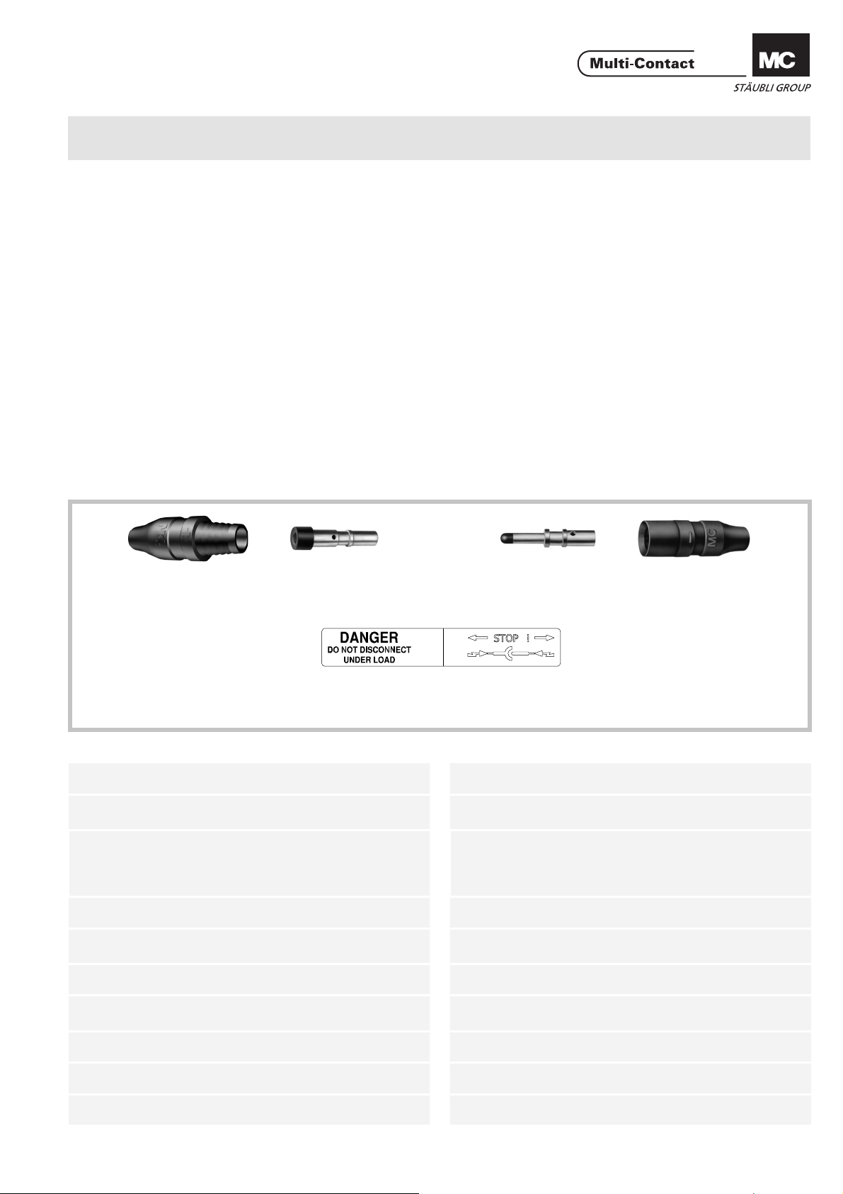
PV-Kupplungsbuchse PV-KBT3...
PV-Kupplungsstecker PV-KST3...
Inhalt
Sicherheitshinweise....................................................................2
Erforderliches Werkzeug ...........................................................3
Anschlussleitung .......................................................................4
Vorbereitung der Leitung ...........................................................4
Crimpanschlüsse .......................................................................4
Crimpen .....................................................................................5
- mit Crimpzange PV-CZM-16100A ...........................................5
- mit Crimpzange PV-CZ ............................................................6
Montage ....................................................................................6
Leitungsführung ........................................................................8
Verbindung ................................................................................8
MA000 (de_en)
MA207 (de_en)
Assembly instructions
Assembly instructions
PV female cable coupler PV-KBT3...
PV male cable coupler PV-KST3...
Content
Safety Instructions ......................................................................2
Tools required ............................................................................3
Connecting cable .......................................................................4
Cable preparation ......................................................................4
Crimp connections ....................................................................4
Crimping ....................................................................................5
- with crimping pliers PV-CZM-16100A .....................................5
- with crimping pliers PV-CZ ......................................................6
Assembly ...................................................................................6
Cable routing .............................................................................8
Engagement ..............................................................................8
PV-T3.../B
PV-T3.../B-UR*
* UL fi le E343181
Technische Daten Technical data
Steckverbindersystem Ø 3mm Connector system Ø 3mm
Bemessungsspannung
Bemessungsstrom
Prüfspannung 6kV (50Hz, 1min.) Test voltage 6kV (50Hz, 1min.)
Umgebungstemperaturbereich
Obere Grenztemperatur 105°C (IEC) Upper limiting temperature 105°C (IEC)
PV-BP3/... PV-SP3/...
Aufkleber
Aufkleber
Sticker
Sticker
1000V DC (IEC)
600V DC (UL)
20A (2,5 – 4mm
14AWG, 12AWG)
30A (6mm2, 10AWG)
43A (10mm2)
-40°C...+90°C (IEC)
-40°C...+75°C (UL)
2;
Rated voltage
Rated current
Ambient temperature range
PV-T3.../S
PV-T3.../S-UR*
1000V DC (IEC)
600V DC (UL)
20A (2,5 – 4mm
14AWG, 12AWG)
30A (6mm2, 10AWG)
43A (10mm2)
-40°C...+90°C (IEC)
-40°C...+75°C (UL)
2;
Schutzart, gesteckt
ungesteckt
Überspannungskat.
Verschmutzungsgrad
Kontaktwiderstand der Steckverbinder
Schutzklasse II Safety class II
www.multi-contact.com 1 / 8
IP67
IP2X
CATIII/2
0,5mΩ
Degree of protection, mated
unmated
Overvoltage category
Pollution degree
Contact resistance of plug connectors
IP67
IP2X
CATIII/2
0,5mΩ
Page 2
Advanced Contact Technology
Sicherheitshinweise Safety Instructions
Die Montage und Installation der Produkte darf nur durch
qualifi ziertes und trainiertes Fachpersonal unter Berücksichti-
gung aller anwendbaren gesetzlichen Sicherheitsbestimmungen und Regelungen erfolgen.
Multi-Contact (MC) lehnt jegliche Haftung infolge Nichteinhaltung dieser Warnhinweise ab.
Benutzen Sie nur die von MC angegebenen Einzelteile und
Werkzeuge. Weichen Sie nicht von den hier beschriebenen
Vorgängen zur Vorbereitung und Montage ab, da sonst bei
der Selbstkonfektionierung weder die Sicherheit noch die
Einhaltung der technischen Daten gewährleistet ist. Ändern
Sie das Produkt nicht in irgend einer Weise ab.
Nicht von MC hergestellte Steckverbindungen, die mit MCElementen steckbar sind und von den Herstellern manchmal
auch als „MC-kompatibel“ bezeichnet werden, entsprechen
nicht den Anforderungen für eine sichere, langzeitstabile
elektrische Verbindung und dürfen aus Sicherheitsgründen
nicht mit MC-Elementen gesteckt werden.
MC übernimmt daher keine Haftung, falls diese von MC
nicht freigegebenen Steckverbindungen mit MC-Elementen
gesteckt werden und deshalb Schäden entstehen.
Die hier beschriebenen Arbeiten dürfen nicht an
stromführenden oder unter Spannung stehenden
Teilen durchgeführt werden.
Der Schutz vor einem elektrischen Schlag muss
durch das Endprodukt gegeben sein und vom Anwender sichergestellt werden.
Die Steckverbindungen dürfen nicht unter Last
getrennt werden. Das Stecken und Trennen unter
Spannung ist zulässig.
Nicht gesteckte Steckverbinder sind mit einer Ver-
schlusskappe (Artikel Nr. 32.0720 für Buchsen und
32.0721 für Stecker) vor Feuchtigkeit und Schmutz
zu schützen. Die Steckverbinder dürfen nicht im verschmutzten Zustand miteinander gesteckt werden.
Die Steckverbindung darf nie einer dauerhaft me-
chanischen Zugbelastung ausgesetzt sein. Das Kabel
sollte mit Kabelbindern befestigt werden.
MC empfi ehlt, weder PVC-Kabel noch unverzinnte
Kabel vom Typ H07RN-F zu verwenden.
The products may be assembled and installed only by suitably
qualifi ed and trained specialists with due observance of all ap-
plicable safety regulations.
Multi-Contact (MC) declines any liability in the event of failure
to observe these warnings.
Use only the components and tools specifi ed by MC. Do not
deviate from the preparation and assembly procedures described here, since in this event, in the event of self-assembly, no
guarantee can be given as to safety or conformity with the
technical data. Do not modify the product in any way.
Connectors not made by MC which can be mated with MC
elements and in some cases are also described as ”MC-compatible” do not conform to the requirements for safe electrical connection with long-term stability, and for safety reasons
must not be plugged together with MC elements. MC can
therefore accept no liability for damage which occurs as a result of mating these connectors which lack MC approval with
MC elements.
The work described here must not be carried out
on live or load-carrying parts.
Protection from electric shock must be assured by
the end product and its user.
The plug connections must not be disconnected
under load. Plugging and unplugging when live is
permitted.
Unmated plug connectors must be protected from
moisture and dirt with a sealing cap (MC3 Article
No. 32.0720 sockets and 32.0721 for plugs). The
male and female parts must not be plugged together
when soiled.
The plug connection must not be subjected to conti-
nuous mechanical tension. The cable should be fi xed
with cable binders.
MC does not recommend the use of either PVC
cables or untinned cables of type H07RN-F.
Weitere technische Daten entnehmen Sie bitte dem
Produktkatalog.
For further technical data please see the product
catalogue.
Erklärung der Symbole Explanation of the symbols
Warnung vor gefährlicher elektrischer Spannung
Warnung vor einer Gefahrenstelle Warning of a hazard area
Nützlicher Hinweis oder Tipp Useful hint or tip
2 / 8 www.multi-contact.com
Warning of dangerous voltages
Page 3
Advanced Contact Technology
Erforderliches Werkzeug Tools required
PV-CZ
Lokator
Locator
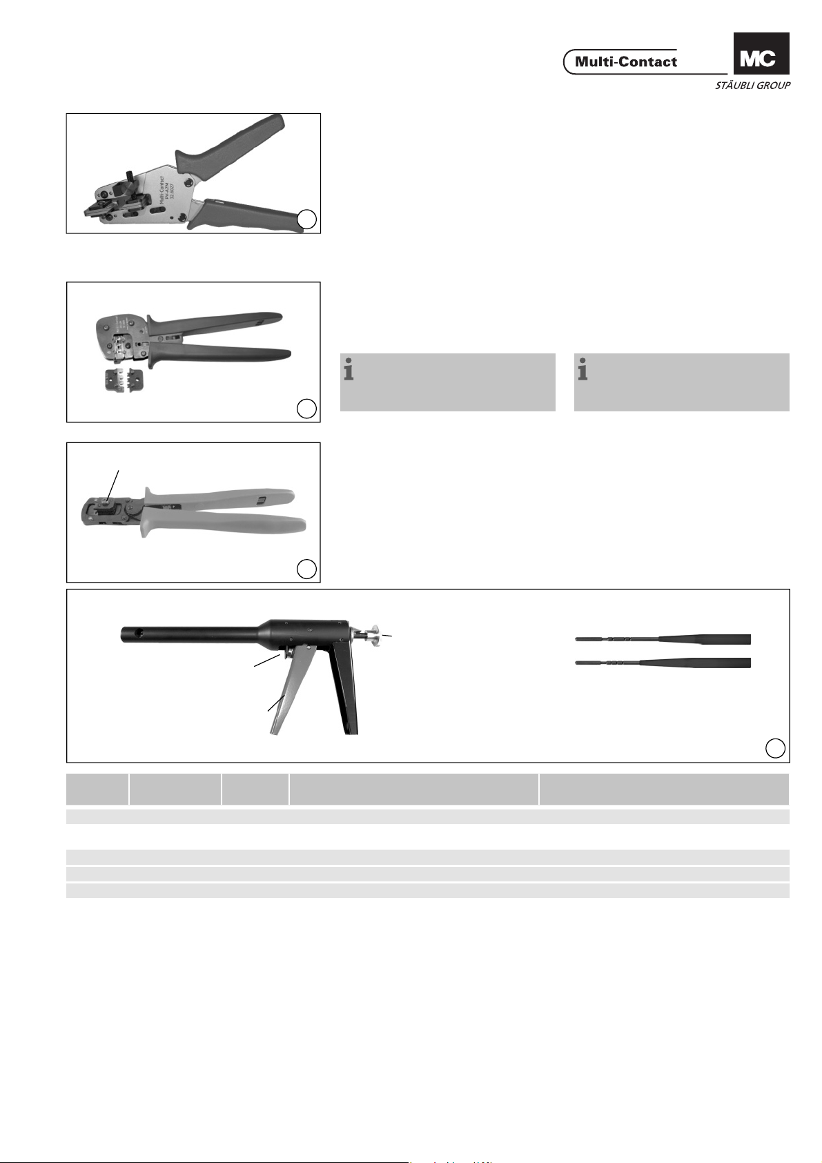
PV-CZM-16100A
UL File 343181
(ill. 1)
Abisolierzange PV-AZM... inkl
eingebauten Abisolier-Messer sowie
Sechskantschlüssel SW 2,5.
Leiterquerschnitt: 1,5 / 2,5 / 4 / 6mm²
1
Typ: PV-AZM-1.5/6
Bestell-Nr. 32.6029-156
(ill. 2)
Crimpzange PV-CZM-16100A für
Leitungsquerschnitte von 2,5mm² 6mm² (14/12 AWG)
Bestell-Nr.: 32.6020-16100A
Hinweis:
zur Bedienung der Crimpzange,
siehe MA251 (www.multi-contact.
com).
2
oder
Crimpzange PV-CZ für Leitungsquer-
schnitte von 2,5mm² - 4mm²
Bestell-Nr.: 32.6008
(ill. 3)
Montagegerät PV-RWZ3 inkl. 2
Konen
Bestell-Nr.: 32.6021-16100
2
(ill. 1)
Stripping pliers PV-AZM... incl.
built-in wire stripping blade as well as
hexagonal screwdriver A/F 2,5.
Cable cross section: 1,5 / 2,5 / 4 / 6mm²
Type: PV-AZM-1.5/6
Order No.: 32.6029-156
(ill. 1)
Crimping pliers PV-CZM-16100A for
cable cross section of 2,5mm² - 6mm²
(14/12 AWG)
Order No.: 32.6020-16100A
Notes:
to the operation of the crimping
pliers, see MA251 (www.multi-contact.com)
or
Crimping pliers PV-CZ for cable cross
section of 2,5mm² and 4mm²
Order No.: 32.6008
(ill. 3)
Assembly device PV-RWZ3 incl. 2
tapered spindles
Order No.: 32.6021-16100
1
UL fi le 343181
Pos.
Typ
Type
Rückstellhebel
Reset lever
Betätigungshebel
Operating lever
Bestell-Nr.
Order No.
Bezeichnung Description
Zugstange
Pull rod
2
3
Konus
Tapered spindle
1 + 2 + 3 PV-RWZ3 32.6050 Montagegerät inklusive 2 Konen Assembly device incl. 2 tapered spindles
Einzelteile Individual parts
1 PV-R-RWZ3 32.6051 Montagegerät Assembly device
2 PV-KO3 I+II 32.6052 Konus für Isolationen Gr. I + II Tapered spindle for insulators size I + II
3 PV-KO3 III 32.6053 Konus für Isolationen Gr. III Tapered spindle for insulators size III
3
www.multi-contact.com 3 / 8
Page 4

Advanced Contact Technology
Anschlussleitung Connecting cable
HG
Tab. 1
Grösse
Size
I 2,8 3,2 – 4,8
II 4,0 4,9 – 7,1
III 6,0 6,5 – 9
G (mm) H (mm)
(ill. 4 / Tab.1)
Sicherstellen der Dichtheit des PVSteckverbinders mit der Leitung:
4
Der Einsatz von mehrdrahtigen Leitern
in AWG-Abmessungen ist möglich.
Überprüfen Sie den Durchmesser der
Kabeldurchführung G für den entsprechenden Kabeldurchmesser nach
Illustration 4 und Tabelle 1.
Achtung:
Achten Sie bei der Auswahl von
doppelt isolierten Anschlussleitungen darauf, dass ein ausreichender Haftsitz zwischen den
Isolationsschichten gegeben ist.
Andernfalls könnten sich die Isolationsschichten gegeneinander
verschieben oder auf dem Leiter
rutschen.
(ill. 4 / Tab.1)
Ensure that there is a tight seal between the male PV coupler and the
cable:
It is possible to use multiple-wire
cables in AWG dimensions.
Check on the basis of illustration 4
and table 1 that the lead-through G
has the correct diameter for the cable.
Attention:
When choosing double-insulated
connecting leads, take care that
there is suffi cient adhesion bet-
ween the layers of insulation.
If this is not the case, the layers
can slide over each other or shift
on the conductor.
Vorbereitung der Leitung Cable preparation
Anschlussleitungen mit einem Litzenaufbau der Klassen 5 und 6 können
angeschlossen werden.
Achtung:
Verwenden Sie keine blanken
oder bereits oxydierten Leiter.
Verzinnte Leiter sind vorteilhaft.
Sämtliche Solarkabel von MC
haben hochwertige, verzinnte
Leiter.
Cables with a strand construction of
classes 5 and 6 can be connected.
Attention:
Use no uncoated or already oxidised conductors. It is advantage
to use tinned conductors. All MC
solar cables have high-quality,
tinned conductors.
L
Tab. 2
Ty p
Type
PV-BP3/4 6.0 - 7.5
PV-SP3/4 6.0 - 7.5
PV-BP3/6 8.5 - 9.5
PV-SP3/6 8.5 - 9.5
Länge L (mm)
Length L (mm)
(ill. 5)
Leitung abisolieren.
Länge gemäss Tab.2.
Achtung:
Schneiden Sie beim Abisolieren
keine Einzeldrähte ab!
Hinweis:
zur Bedienung der Abisolierzange
PV-AZM... sowie zum Auswech-
5
seln von Messersätzen entnehmen
Sie bitte der Bedienungsanleitung
MA267 auf www.multi-contact.com
(ill. 5)
Strip cable insulation.
Length according to Tab.2.
Attention:
Do not cut individual strands at
stripping
Note:
For directions on the use of stripping pliers PV-AZM... and changing
blade sets, see operating instruction
MA267 at www.multi-contact.com
Crimpanschlüsse Crimp connections
Für den Leiteranschluss an die
Crimphülsen der PV-Steckverbinder
empfehlen wir, die angegebenen
Crimpwerkzeuge einzusetzen. Die
Crimphülsen sind für fl exible Leiter
(Klassen 5 und 6 nach IEC 60228, DIN
VDE 0295) mit Leitungsquerschnitten
von 2.5mm² bis 10mm² ausgelegt.
For connecting the conductors to the
crimp sleeves of the PV couplers, we
recommend using the stated crimping
tools. The crimping sleeves are designed for fl exible wires (classes 5 and
6 according to IEC 60228, DIN VDE
0295) with conductor cross-sections
of 2.5mm² to 10mm².
4 / 8 www.multi-contact.com
Page 5

Advanced Contact Technology
Crimpen Crimping
mit Crimpzange PV-CZM-16100A
für Leiterquerschnitte von
2,5mm², 4mm² und 6mm²
Diese Crimpzange verfügt über auswechselbare Crimpeinsätze für folgende Leitungsquerschnittsbereiche:
1) 2.5 / 4 / 6mm
2
(14 / 12 / 10 AWG)
2) 4 / 10mm2 (12 AWG)
In der folgenden Beschreibung des
Crimpvorgangs wurden Bilder zum
Querschnittsbereich (1) verwendet.
Der Crimpvorgang für den Querschnittsbereich (2) ist identisch.
Weitere Hinweise zum Bedienen der
Crimpzange, zum Auswechseln der
Crimpeinsätze sowie der entsprechenden Locators entnehmen Sie bitte
der Bedienungsanleitung MA251 auf
www.multi-contact.com
(ill. 6)
Legen Sie das Metallteil von Buchse
oder Stecker in die Führung für den
entsprechenden Querschnitt ein.
Führen Sie die Leitung bis zum Anschlag in die Crimphülse ein. Halten
Sie die Leitung in der Hülse fest.
with crimping pliers PV-CZM16100A
for cable cross section 2,5mm²,
4mm² and 6mm²
This crimping tool is equipped with interchangeable crimping inserts for the
following wire cross-section ranges:
1) 2.5 / 4 / 6mm
2
(14 / 12 / 10 AWG)
2) 4 / 10mm2 (12 AWG)
In the following description of the
crimping process, illustrations from
cross section range (1) have been
used. The crimping procedure for
cross-section range (2) is identical.
For further hints on the operation of
the crimping tool and for changing the
crimping inserts and the appropriate
locators, please see operating instruction MA251 at www.multi-contact.
com
(ill. 6)
Place the metal part of the female
or male coupler in the guide for the
appropriate cross section. Insert the
wire into the crimping sleeve as far as
it will go. Hold the wire in place in the
sleeve.
6
S
max. 1 mm
(ill. 7)
Achtung:
Alle Drähte der Litze müssen
7
sauber in der Bohrung eingeführt
und im Sichtloch S sichtbar sein.
Der Abstand max. 1mm darf
nicht überschritten werden.
(ill. 7)
Attention:
All strands of the wires must be
correctly inserted into the borehole and visible in sight hole S.
The max. distance of 1mm must
not be exceeded.
Schliessen Sie die Crimpzange ganz. Completely close the crimping tool.
(ill. 8)
Kontrollieren Sie die Vercrimpung
(ill. 8)
Visually check the crimp
visuell.
8
www.multi-contact.com 5 / 8
Page 6

Advanced Contact Technology
S
max. 1 mm
mit Crimpzange PV-CZ
für Leitungsquerschnitte von 2,5
und 4mm²
(ill. 9)
Legen Sie das Metallteil von Buchse
oder Stecker in die Führung für den
entsprechenden Querschnitt ein.
Führen Sie die Leitung bis zum Anschlag in die Crimphülse ein. Halten
9
Sie die Leitung in der Hülse fest.
9
(ill. 10)
Achtung:
Alle Drähte der Litze müssen
sauber in der Bohrung eingeführt
und im Sichtloch S sichtbar sein.
Der Abstand max. 1mm darf
10
nicht überschritten werden.
with crimping pliers PV-CZ
for cable cross section 2,5 and
4mm²
(ill. 9)
Place the metal part of the female
or male coupler in the guide for the
appropriate cross section. Insert the
wire into the crimping sleeve as far as
it will go. Hold the wire in place in the
sleeve.
(ill. 10)
Attention:
All strands of the wires must be
correctly inserted into the borehole and visible in sight hole S.
The max. distance of 1mm must
not be exceeded.
Industriealkohol
Industrial alcohol
alcool industriel
Schliessen Sie die Crimpzange ganz.
(ill. 11)
Kontrollieren Sie die Vercrimpung
visuell.
11
Montage Assembly
(ill. 12)
Hinweis:
Sie können den Montagevorgang
erleichtern, indem Sie die Kabeldurchführung der Steckverbinderisolation in Industriealkohol tauchen,
bevor Sie die Kontakte einsetzen.
12
Completely close the crimping tool.
(ill. 11)
Visually check the crimp.
(ill. 12)
Note:
You can facilitate the assembly procedure by immersing the connector
insulators in industrial alcohol before
inserting the contacts.
6 / 8 www.multi-contact.com
Page 7

Advanced Contact Technology
PV-KO3 I+II
Rillen / Grooves
40 mm min.
(ill. 13)
Halten Sie das Montagegerät am
Einzugsrohr fest.
Drücken Sie den Rückstellhebel R mit
dem Daumen in Pfeilrichtung und
schieben Sie gleichzeitig die Zugstange Z mit der andern Hand bis zum
Anschlag ein.
13
(ill. 14)
Wählen Sie den Konus aus:
• PV-KO3 I+II für Buchsen- und Steckerisolationen der Grössen I und II
• PV-KO3 III für Buchsen- und Steckerisolationen der Grösse III
Stossen Sie den Konus von hinten
durch die Buchsen- bzw. Steckerisolation, bis der Zugstift ca. 40mm aus der
14
Buchsen- bzw. Steckerisolation ragt.
(ill. 15)
Führen Sie die Buchse oder den
Stecker mit angecrimpter Leitung in
den Konus ein.
15
(ill. 16)
Führen Sie den Konus in das Montagegerät ein und hängen ihn am
Konushalter ein. Halten Sie dabei die
Zugstange fest.
(ill. 13)
Hold the assembly tool by the pull-in
tube.
Press the return lever R with the
thumb in the direction of the arrow
and at the same time press in the
puller rod Z to the limit with the other
hand.
(ill. 14)
Select the appropriate tapered spindle:
• PV-KO3 I+II for male and female
coupler insulators of sizes I and II
• PV-KO3 III for male and female
coupler insulators of size III
Push the tapered spindle from behind
into the male or female insulator until
the puller rod protrudes from the male
or female insulator by approx. 40mm.
(ill. 15)
Insert the male or female coupler
with crimped-on lead into the tapered
spindle.
(ill. 16)
Insert the tapered spindle into the
assembly tool and attach it to the
spindle holder. During this operation
hold the puller rod in position.
16
(ill. 17)
Betätigen Sie den Werkzeuggriff
mehrfach. Dadurch ziehen Sie den Konus durch den Werkzeugeinlauf. Halten Sie dabei die Leitung mit leichtem
17
Druck im Konus, bis das Stecker- bzw.
Buchsenteil in der Isolation einrastet.
Ziehen Sie den Konus komplett aus
der Isolation heraus.
(ill. 18)
Ziehen Sie die Buchse bzw. den Stecker aus dem Montagegerät.
18
(ill. 19)
Stellen Sie die Zugstange Z zurück.
Nehmen Sie den Konus K aus dem
Montagegerät.
19
(ill. 17)
Actuate the handle of the tool several
times. This pulls the tapered spindle
through the infeed opening of the
tool. Apply gentle pressure to keep
the lead in the spindle until the male
or female coupler part engages in
the insulator. Pull the tapered spindle
completely out of the insulator.
(ill. 18)
Withdraw the male or female coupler
from the assembly tool.
(ill. 19)
Return the puller rod Z to its starting
position.
Remove the tapered spindle K from
the assembly tool.
www.multi-contact.com 7 / 8
Page 8

Advanced Contact Technology
(ill. 20)
Stellen Sie durch leichtes Ziehen an
der Leitung sicher, dass die Tülle auf
dem Metallteil richtig eingerastet ist.
Bei richtiger Einbaulage müssen die
eingebauten Teile mit der Isolations-
20
Stirnseite bündig sein.
(ill. 21)
Bringen Sie den beiliegenden Aufkleber „DANGER – DO NOT DISCONNECT UNDER LOAD“ in der Nähe des
PV-Kupplungssteckers an.
21
(ill. 20)
Pull gently on the lead to check that
the sleeve is correctly locked in place
on the metal part.
If it is correcly located, the fi tted parts
must be fl ush with the front face of
the insulator.
(ill. 21)
Affi x the supplied sticker “DANGER
– DO NOT DISCONNECT UNDER
LOAD” in the vicinity of the PV coupler.
Leitungsführung Cable routing
Beachten Sie die Spezifi kationen des
Leitungsherstellers betreffend Biegeradius.
Refer to cable manufactures specifi ca-
tion for minimum bending radius.
Hersteller/Producer:
Multi-Contact AG
Stockbrunnenrain 8
CH – 4123 Allschwil
Tel. +41/61/306 55 55
Fax +41/61/306 55 56
mail basel@multi-contact.com
www.multi-contact.com
Verbindung Engagement
Stellen Sie sicher, dass die Steckverbinder vollständig geschlossen sind.
Check that the coupler parts are fully
engaged.
© by Multi-Contact AG, Switzerland – MA207 – 10.2011, index k , Global Communications – Änderungen vorbehalten / Subject to alterations
 Loading...