

Multi-Contact PV-ADSP4/2, 5, PV-ADSP4/6, PV-ADBP4/2, PV-ADBP4/6 Assembly Instructions Manual
Page 1
Advanced Contact Technology
www.multi-contact.com 1 / 8
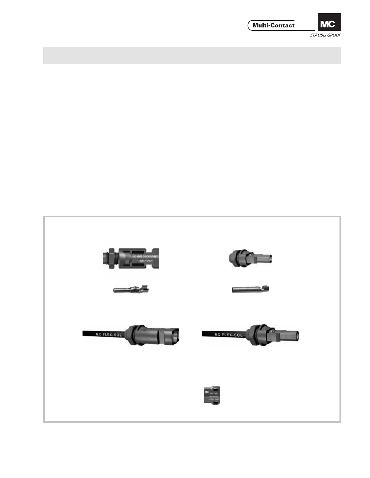
PV-ADSP4/... PV-ADBP4/...
MC-K.../PV-ADSP4/... MC-K.../PV-ADBP4/...
MA000 (de_en)
Montageanleitung
MA000 (de_en)
Assembly instructions
MA232 (de_en)
Montageanleitung
MA232 (de_en)
Assembly instructions
PV Aufbaudosenbuchse PV-ADBP4/...
PV Aufbaudosenstecker PV-ADSP4/...
PV Aufbaudosenbuchse mit Leitung
MC-K.../PV-ADBP4/...
PV Aufbaudosenstecker mit Leitung
MC-K.../PV-ADSP4/...
PV Female panel receptacle PV-ADBP4/...
PV Male panel receptacle PV-ADSP4/...
PV Female panel receptacle with cable
MC-K.../PV-ADBP4/...
PV Male panel receptacle with cable
MC-K.../PV-ADSP4/...
Inhalt
Sicherheitshinweise....................................................................2
Erforderliches Werkzeug ...........................................................3
Montage ....................................................................................4
Crimpen .....................................................................................4
Montage der Aufbaudosen........................................................4
Montage-Prüfung ......................................................................5
Stecken und Trennen .................................................................5
Leitungsführung ........................................................................7
Notizen ......................................................................................8
Content
Safety Instructions ......................................................................2
Tools required ............................................................................3
Assembly ...................................................................................4
Crimping ....................................................................................4
Installation of the panel receptacles ..........................................4
Assembly check ........................................................................5
Plugging and unplugging ..........................................................5
Cable routing .............................................................................7
Notes .........................................................................................8
Aufbaudosenstecker
Male panel receptacle
Aufbaudosenbuchse
Female panel receptacle
mit Leitung
with cable
mit Leitung
with cable
Optional
(siehe/see MA252)
PV-SSH4
Sicherungshülse
Safety lock clip
Page 2
Advanced Contact Technology
2 / 8 www.multi-contact.com
Sicherheitshinweise Safety Instructions
Die Montage und Installation der Produkte darf nur durch qualifi ziertes und trainiertes Fachpersonal unter Berücksichtigung
aller anwendbaren gesetzlichen Sicherheitsbestimmungen
und Regelungen erfolgen.
Multi-Contact (MC) lehnt jegliche Haftung infolge Nichteinhaltung dieser Warnhinweise ab.
The products may be assembled and installed only by suitably
qualifi ed and trained specialists with due observance of all ap-
plicable safety regulations.
Multi-Contact (MC) declines any liability in the event of failure
to observe these warnings.
Benutzen Sie nur die von MC angegebenen Einzelteile und
Werkzeuge. Weichen Sie nicht von den hier beschriebenen
Vorgängen zur Vorbereitung und Montage ab, da sonst bei der
Selbstkonfektionierung weder die Sicherheit noch die Einhaltung der technischen Daten gewährleistet ist. Ändern Sie das
Produkt nicht in irgend einer Weise ab.
Use only the components and tools specifi ed by MC. Do not
deviate from the preparation and assembly procedures described here, since in this event, in the event of self-assembly, no
guarantee can be given as to safety or conformity with the
technical data. Do not modify the product in any way.
Nicht von MC hergestellte Steckverbindungen, die mit MCElementen steckbar sind und von den Herstellern manchmal
auch als „MC-kompatibel“ bezeichnet werden, entsprechen
nicht den Anforderungen für eine sichere, langzeitstabile elektrische Verbindung und dürfen aus Sicherheitsgründen nicht
mit MC-Elementen gesteckt weren. MC übernimmt daher keine Haftung, falls diese von MC nicht freigegebenen Steckverbindungen mit MC-Elementen gesteckt werden und deshalb
Schäden entstehen.
Connectors not made by MC which can be mated with MC
elements and in some cases are also described as ”MC-compatible” do not conform to the requirements for safe electrical connection with long-term stability, and for safety reasons
must not be plugged together with MC elements. MC can
therefore accept no liability for damage which occurs as a result of mating these connectors which lack MC approval with
MC elements.
Die hier beschriebenen Arbeiten dürfen nicht an
stromführenden oder unter Spannung stehenden
Teilen durchgeführt werden.
The work described here must not be carried out
on live or load-carrying parts.
Der Schutz vor einem elektrischen Schlag muss
durch das Endprodukt gegeben sein und vom Anwender sichergestellt werden.
Protection from electric shock must be assured by
the end product and its user.
Die Steckverbindungen dürfen nicht unter Last
getrennt werden. Das Stecken und Trennen unter
Spannung ist zulässig.
The plug connections must not be disconnected
under load. Plugging and unplugging when live is
permitted.
Die Steckverbinder sind wasserdicht gemäss IP-
Schutzart. Sie sind aber nicht geeignet für einen
dauerhaften Gebrauch unter Wasser. Legen Sie die
Steckverbinder nicht direkt auf die Dachhaut auf.
The plug connectors are watertight in accordance
with IP protection class. However, they are not
suitable for continuous operation under water. Do
not place the plug connectors directly on the roof
membrane.
Nicht gesteckte Steckverbinder sind mit einer Ver-
schlusskappe (MC4 Artikel Nr. 32.0716 für Buchsen und 32.0717 für Stecker) vor Feuchtigkeit und
Schmutz zu schützen. Die Steckverbinder dürfen
nicht im verschmutzten Zustand miteinander gesteckt werden.
Unmated plug connectors must be protected from
moisture and dirt with a sealing cap (MC4 Article
No. 32.0716 sockets and 32.0717 for plugs). The
male and female parts must not be plugged together
when soiled.
Die Steckverbindung darf nie einer dauerhaft me-
chanischen Zugbelastung ausgesetzt sein. Das Kabel
sollte mit Kabelbindern befestigt werden.
The plug connection must not be subjected to conti-
nuous mechanical tension. The cable should be fi xed
with cable binders.
MC empfi ehlt, weder PVC-Kabel noch unverzinnte
Kabel vom Typ H07RN-F zu verwenden.
MC does not recommend the use of either PVC
cables or untinned cables of type H07RN-F.
Weitere technische Daten entnehmen Sie bitte dem
Produktkatalog.
For further technical data please see the product
catalogue.
Erklärung der Symbole Explanation of the symbols
Warnung vor gefährlicher elektrischer Spannung
Warning of dangerous voltages
Warnung vor einer Gefahrenstelle Warning of a hazard area
Nützlicher Hinweis oder Tipp Useful hint or tip
Page 3
Advanced Contact Technology
www.multi-contact.com 3 / 8
1
2
3
4
5
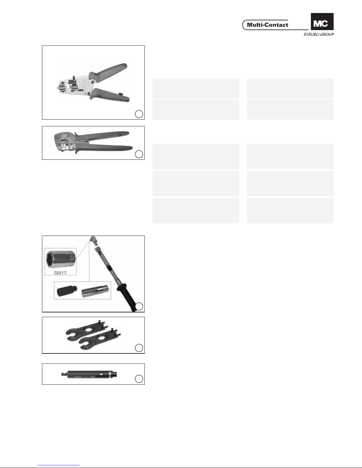
Erforderliches Werkzeug Tools required
(ill. 1)
Abisolierzange PV-AZM... inkl
eingebauten Abisolier-Messer sowie
Sechskantschlüssel SW 2,5.
Leiterquerschnitt: 1,5 / 2,5 / 4 / 6mm²
Typ: PV-AZM-1.5/6
Bestell-Nr. 32.6027-156
Leiterquerschnitt: 4 / 6 / 10mm²
Typ: PV-AZM-4/10
Bestell-Nr. 32.6027-410
(ill. 1)
Stripping pliers PV-AZM... incl.
built-in wire stripping blade as well as
hexagonal screwdriver A/F 2,5.
Cable cross section: 1,5 / 2,5 / 4 / 6mm²
Type: PV-AZM-1.5/6
Order No.: 32.6027-156
Cable cross section: 4 / 6 / 10mm²
Type: PV-AZM-4/10
Order No.: 32.6027-410
(ill. 2)
Crimpzange PV-CZM... inkl Locator
und eingebautem Crimpeinsatz
Crimpbereich:
1,5 / 2,5 / 4mm² (14/12 AWG)
Typ: PV-CZM-18100
Bestell-Nr. 32.6020-18100
Crimpbereich:
2,5 / 4 / 6mm² (12/10 AWG)
Typ: PV-CZM-19100
Bestell-Nr. 32.6020-19100
Crimpbereich:
4 / 10mm
2
(12 AWG)
Typ: PV-CZM-20100
Bestell-Nr. 32.6020-20100
(ill. 2)
Crimping pliers PV-CZM... incl Locator and built-in crimping insert
Crimping ranges:
1,5 / 2,5 / 4mm² (14/12 AWG)
Type: PV-CZM-18100
Order No. 32.6020-18100
Crimping ranges:
2,5 / 4 / 6mm² (12/10 AWG)
Type: PV-CZM-19100
Order No. 32.6020-19100
Crimping ranges:
4 / 10mm
2
(12 AWG)
Type: PV-CZM-20100
Order No. 32.6020-20100
(ill. 3)
Drehmomentschüssel, 2Nm
• PV-WZ-AD/GWD Steckschlüsseleinsatz zum Anziehen (für Kabel- Ø
max. 10mm):
Bestell-Nr. 32.6006
• PV-SSE-AD4 Steckschlüssel zum
Kontern:
Bestell-Nr. 32.6026
(ill. 3)
Torque wrench, 2Nm
• PV-WZ-AD/GWD special wrench
insert (for cable Ø max. 10mm):
Order No. 32.6006
• PV-SSE-AD4 special wrench inset
(to tighten):
Order No. 32.6026
(ill. 4)
PV-MS Montageschlüssel,
1 Set = 2 Stück
Bestell-Nr.: 32.6024
(ill. 4)
Open-end spanner PV-MS,
1 Order No. = 2 pieces
Order No.: 32.6024
(ill. 5)
PV-PST Prüfstift
Bestell-Nr.: 32.6028
(ill. 5)
Test plug PV-PST
Order No.: 32.6028
Page 4

Advanced Contact Technology
4 / 8 www.multi-contact.com
6
b
b
L=6 - 7,5mm
7
max. 7
x
12,5
12,5
+0,2
- 0, 4
+0,2
- 0, 4
8
Tab. 1
Montage Assembly
Anschlussleitungen mit einem Litzenaufbau der Klassen 2,5 und 6 können
angeschlossen werden.
Achtung:
Verwenden Sie keine Kabel vom
Typ H07RN-F, da diese nicht
verzinnt sind. Bei oxidierten
Kupferlitzen besteht die Gefahr,
dass die Übergangswiderstände
der Crimpverbindung die zulässigen Grenzwerte überschreiten
könnten. Verzinnte Leiter sind
vorteilhaft. Sämtliche Solarkabel
von MC haben hochwertige,
verzinnte Leiter.
Cables with a strand construction of
classes 2,5 and 6 can be connected.
Attention:
Do not use cables of type
H07RN-F, since these are not
tinned. In wires with oxidised
copper strands there is a risk that
the contact resistances of the
crimp termination will exceed the
permitted limits. It is advantageous to use tinned conductors. All
MC Solar cables have high-grade,
tinned conductors.
(ill. 6, Tab. 1)
Kontrollieren Sie das Mass b gemäss
Illustration 6 und Tabelle 1.
(ill. 6, Tab. 1)
Check dimension b in accordance
with illustration 6 and table 1.
(ill. 7)
Leitung abisolieren.
Entfernen Sie die Isolation des Kabels
auf einer Länge von 6,0 bis 7,5mm.
Achtung:
Schneiden Sie beim Abisolieren
keine Einzeldrähte ab!
Hinweis:
zur Bedienung der Abisolierzange
PV-AZM... sowie zum Auswechseln von Messersätzen entnehmen
Sie bitte der Bedienungsanleitung
MA267 auf www.multi-contact.com
(ill. 7)
Strip cable insulation.
Remove 6.0 to 7.5mm of insulation
from the end of the cable.
Attention:
Do not cut individual strands at
stripping
Note:
For directions on the operation of
stripping pliers PV-AZM... and changing blade sets, see operating instruction MA267 at www.multi-contact.com
Crimpen Crimping
Hinweis:
zur Handhabung der Crimpzange
entnehmen Sie bitte der Bedienungsanleitung MA251 auf
www.multi-contact.com
Note:
For directions on the operation of
the crimping tool, please see operating instructions MA251 at
www.multi-contact.com
Montage der Aufbaudosen Installation of the panel re-
ceptacles
(ill. 8)
Bohren Sie die Gehäusewand.
(ill. 8)
Drill the box wall.
Bei Horizontal- oder Vertikal-Einbau
empfehlen wir einen Rasterabstand
(X) von mindestens 25mm.
For both horizontal and vertical mounting we recommend a spacing (X) of
at least 25mm.
b: Kontrollmass
b: Control dimension
Leitungsquerschnitt
Conductor cross section
Typ
Type
mm
mm
2
AWG
~ 3 1,5 - 2,5 14 PV-ADSP4/2,5 PV-ADBP4/2,5
~ 5 4 - 6 12 / 10 PV-ADSP4/6 PV-ADBP4/6
Page 5

Advanced Contact Technology
www.multi-contact.com 5 / 8
9
11
12
13
10
(ill. 9)
Richten Sie die Kunststoffteile so aus
(E), dass sie gesteckt und getrennt
werden können. Schrauben Sie die
Muttern (M) fest und ziehen Sie sie
mit 2Nm an.
(ill. 9)
Position the plastic parts (E) so that
they can be plugged and unplugged.
Screw on the nuts (M) and tighten
them to 2Nm.
(ill. 10)
Hinweis:
Wenn die Montage erfordert,
dass die Kontakte fest sitzen, bitte beachten Sie für diesen Zweck
die integrierte Funktion der PVADB4 / PV-ADS4 Isolierung.
(ill. 10)
Note:
If the assembly requires that the
contacts not rotate, please be
aware of the built-in feature of
the PV-ADB4 / PV-ADS4 insulation for this purpose.
Montage-Prüfung Assembly check
(ill. 11)
Führen Sie den angecrimpten Kontakt von hinten in die Isolation ein,
bis er einrastet. Kontrollieren Sie das
Einrasten durch leichtes Ziehen an der
Leitung.
(ill. 11)
Insert the crimped-on contact into
the insulator from the back until it
engages. Check correct engagement
by pulling lightly on the lead.
(ill. 12)
Stecken Sie den Prüfstift mit der entsprechenden Seite in die Buchse bzw.
in den Stecker bis zum Anschlag. Bei
richtig montiertem Kontakt muss die
weisse Markierung am Prüfstift noch
sichtbar sein.
(ill. 12)
Insert the appropriate end of the test
pin into the socket or plug as far as
it will go. If the contact is correctly
assembled, the white mark on the test
pin must still be visible.
Stecken und Trennen Plugging and unplugging
Stecken
(ill. 13)
Stecken Sie die Kabelkupplung zusammen bis zum Einrasten. Kontrollieren Sie das korrekte Einrasten durch
Ziehen an der Kabelkupplung.
Plugging
(ill. 13)
Plug the cable coupler together until it
engages. Check correct engagement
by pulling on the coupler.
weisse Markierung
white mark
ohne Leitung
without cable
mit Leitung
with cable
Page 6

Advanced Contact Technology
6 / 8 www.multi-contact.com
14
15
16
Trennen ohne Sicherungshülse
PV-SSH4
(ill. 14 - 15)
Zum Trennen der Kontakte drücken
Sie die Einrastlaschen (X) entweder
von Hand oder mit dem Werkzeug
PV-MS zusammen und ziehen Sie die
Kabelkupplung auseinander.
Unplugging without safety lock
clip PV-SSH4
(ill. 14 - 15)
To disconect the contacts, press the
latches (X) together either by hand
or with the pool PV-MS and pull the
halves of the cable coupler apart.
Trennen mit Sicherungshülse
PV-SSH4
(ill. 16)
Die Kabelkupplung kann nur noch
mit dem Werkzeug PV-MS getrennt
werden. Drücken Sie die Einrastlaschen mit dem Werkzeug zusammen
und ziehen Sie die Kabelkupplung
auseinander.
Unplugging with safety lock clip
PV-SSH4
(ill. 16)
The cable coupler can be disconnect
only with the tool PV-MS. Press the
latches together with the tool and pull
the halves of the coupler apart.
Page 7

Advanced Contact Technology
www.multi-contact.com 7 / 8
Leitungsführung Cable routing
Beachten Sie die Spezifi kationen des
Leitungsherstellers betreffend Biegeradius.
Refer to cable manufactures specifi ca-
tion for minimum bending radius.
Page 8

Advanced Contact Technology
Hersteller/Producer:
Multi-Contact AG
Stockbrunnenrain 8
CH – 4123 Allschwil
Tel. +41/61/306 55 55
Fax +41/61/306 55 56
mail basel@multi-contact.com
www.multi-contact.com
© by Multi-Contact AG, Switzerland – MA232 – 05.2011, Index f, Global Communications – Änderungen vorbehalten / Subject to alterations
Notizen / Notes:
 Loading...