

Page 1
Advanced Contact Technology
MA283 (es_en)
Instrucciones de montaje
MA283 (es_en)
Assembly instructions
Herramienta crimpadora PICO PICO-Crimper
Índice
Instrucciones de seguridad .................................................... 2-3
Lista de piezas ��������������������������������������������������������������������������4
Instrucciones de instalación ������������������������������������������������������4
MC4-8AWG Pico Crimp Tooling Set
Content
Safety Instructions .................................................................. 2-3
Parts list .....................................................................................4
Installing instructions ................................................................4
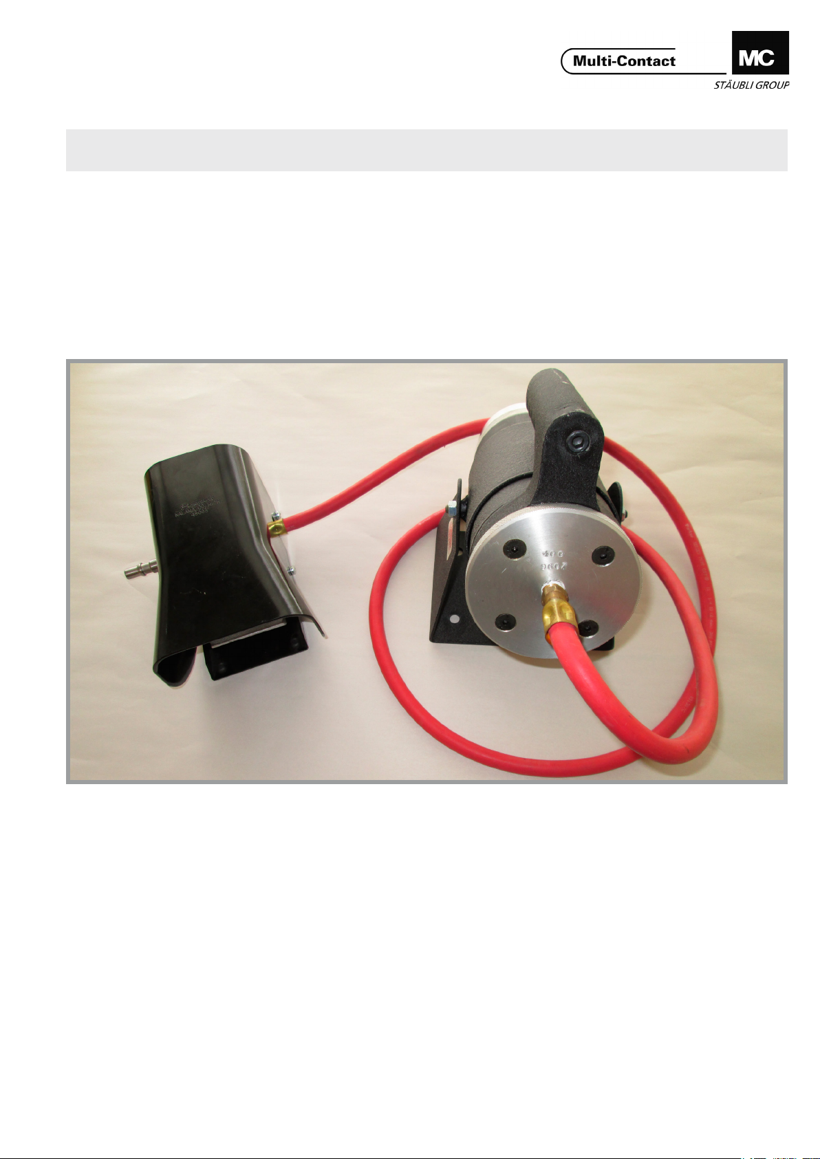
Descripción:
Esta herramienta crimpadora de ciclo integral realiza cuatro
muescas dobles con precisión en los contactos fotovoltaicos
(PV) incluidos en la lista que encontrará más adelante, para lo
que se utilizan el pedal suministrado o el pulsador del mango� La herramienta trae un soporte para su uso en banco de
trabajo y funciona con aire comprimido estándar� Para termina-
ciones in situ puede usar una botella portátil de gas inerte, por
ejemplo, de nitrógeno.
Suministro de aire:
Utilice gas inerte o aire comprimido corriente ltrado de 80
– 125 psi� Se recomienda que el tubo para el aire tenga un Ø
exterior de 3/8“ e interior de 1/4“� No utilice engrasadores�
www.multi-contact.com 1 / 8
Description:
This full cycle crimp tool accurately positions four double
indent crimps onto the PV contact listed below using either
the supplied foot control or the handle push button� The tool
comes with a stand for bench use and is powered by standard
shop air supplies. For eld terminations, a portable tank of inert
gas, such as nitrogen, can be used.
Air Supply:
Use 80-125 psi of ltered shop air or inert gas. Air line should
be Ø3/8” OD and Ø1/4” ID� Do not use an oiler�
Page 2
Advanced Contact Technology
Instrucciones de seguridad Safety instructions
Estas instrucciones de montaje y los pasos e indicaciones en
ellas descritos para el montaje forman parte de las certicaciones TÜV y UL, es decir, son los requisitos para su obtención.
El montaje y la instalación de los productos solamente podrán
ser realizados por personal cualicado y especializado con experiencia, teniendo en cuenta tanto la norma de instalaciones
DIN VDE-0100-712 (IEC 60364-7-712) como todas las normas
de seguridad y reglamentos nacionales e internacionales aplicables por ley� Multi-Contact (MC) no se responsabiliza ante el
incumplimiento de estas advertencias�
Este producto ha sido certicado exclusivamente como componente fotovoltaico� El responsable único de su elaboración
y condiciones de uso es el fabricante de los módulos, que ha
de garantizar que el conjunto del sistema sea adecuado para
los nes para los que ha sido diseñado, recurriendo para ello
a las pruebas oportunas, llevadas a cabo por él mismo, y, nalmente, a la certicación del módulo fotovoltaico junto con
todos los componentes y piezas�
Utilice sólo los componentes y herrmientas indicadas por MC�
No se desvíe de los procedimientos de preparación y montaje
aquí descritos, en caso de una manipulación inadecuada no
se podrá garantizar la seguridad ni la conformidad con los da-
tos técnicos. No modique el prodcuto en ningún caso.
Los conectores no fabricados por MC que se pueden conectar
con elementos MC, a veces denominados por los fabricantes
como „compatibles con MC“ no cumplen con los requisitos
para una conexión eléctrica segura y estable a largo plazo.
No pueden conectarse con elementos MC por motivos de se-
guridad. Por tanto, MC no se responsabilizará de los daños
surgidos por la conexión de conectores no autorizados por
MC con elementos MC�
Los trabajos aquí descritos no pueden ejecutarse
en piezas conectadas a la red y con tensión.
El producto nal debe proporcionar protección al
usuario frente a una descarga eléctrica.
Los conectores no pueden separarse estando cargados. Se permite la conexión y desconexión con
tensión.
Los conectores son impermeables según el tipo de
protección IP. Pero no están indicados para un largo
uso bajo agua. No coloque los conectores directamente sobre una cubierta.
Las tensiones nominales indicadas son valores máxi-
mos que solamente hacen referencia a los conecto-
res. La tensión nominal nal viene determinada por la
tensión nominal máxima más baja de un conjunto y
las normas pertinentes por las que estos hayan sido
evaluados y certicados.
Se deben proteger ante la humedad y suciedad los
conectores no conectados con una tapa de cierre
(MC4 nº de artículo 32.0716 para bornes y 32.0717
para enchufes). No se pueden conectar conectores
sucios.
These assembly instructions and the assembly steps and instructions described are an integral part of and prerequisite for
certication by TÜV and UL.
The assembly and installation of the products must only be
carried out by qualied and experienced specialist personnel
in compliance with the installation standard DIN VDE 0100712 (IEC 60364-7-712) and all applicable national and international statutory safety regulations and conditions� Multi-Contact (MC) does not accept any liability in the event of failure to
observe these warnings�
This product is certied exclusively as a photovoltaic component� The module manufacturer is solely responsible for its
handling and conditions of use� The module manufacturer
must assure, by carrying out their own, appropriate tests and
the subsequent certication of the photovoltaic model with all
components and parts, that the complete system is suitable
for its intended application�
Use only the components and tools specied by MC. In case
of self-assembly, do not deviate from the preparation and assembly instructions as stated herein, otherwise MC cannot
give any guarantee as to safety or conformity with the technical data� Do not modify the product in any way�
Connectors not originally manufactured by MC which can
be mated with MC elements and in some cases are even
described as ”MC-compatible” by certain manufacturers do
not conform to the requirements for safe electrical connec-
tion with long-term stability, and for safety reasons must not
be plugged together with MC elements� MC therefore does
not accept any liability for any damages resulting from mating
such connectors (i.e. lacking MC approval) with MC elements.
The work described here must not be carried out
on live or load-carrying parts.
Protection from electric shock must be assured by
the end product (i.e. by the correctly assembled
plug connector) and by its user.
The plug connections must not be disconnected
under load. Plugging and unplugging when live is
permitted.
The plug connectors are watertight in accordance
with the product specic IP protection class. However, they are not suitable for continuous operation under water. Do not place the plug connectors directly
on the roof membrane.
Stated voltage ratings are maximum values and per-
tain only to the cable couplers. The nal voltage rating of a cable lead assembly or harness is dictated
by the lowest maximum voltage rating of any component contained in the assembly and the relevant
standards to which they have been evaluated and cer-
tied.
Unmated plug connectors must be protected from
moisture and dirt with a sealing cap (MC4 article No.
32.0716 for sockets and 32.0717 for plugs). The male
and female parts must not be plugged together when
soiled.
2 / 8 www.multi-contact.com
Page 3
Advanced Contact Technology
El conector no debe someterse nunca a una tracción
mecánica duradera. El cable debe jarse con bridas.
Téngase en cuenta la posición de montaje precisada.
El producto ha de utilizarse exclusivamente según las
especicaciones indicadas en los datos técnicos (por
ejemplo, mantener las temperaturas permitidas con
una ventilación suciente por la parte posterior).
El producto no ha sido diseñado para cargas de trac-
ción excesivas (por ejemplo, para que el cable soporte
los módulos), por lo que habrán de evitarse.
Asegúrese de disponer siempre de las instrucciones
de montaje más recientes (enlace a la página de MC).
Ni los componentes ni los embalajes son juguetes;
peligro de ingerir piezas pequeñas. Peligro de asxia
al manipular los embalajes.
Una vez utilizados, eliminar los productos y embala-
jes como corresponde.
Encontrará más detalles técnicos en el catálogo del
producto.
The plug connection must not be subjected to contin-
uous mechanical tension. The cable should be xed
with cable binders.
The dened mounting position must be complied
with.
Use only in accordance with the specication pro-
vided in the technical data (e.g. compliance with
approved temperatures by providing sufcient back
ventilation).
Excessive tensile load (e.g. by carrying the modules
by the cables) does not comply with the intended use
and must therefore be avoided.
Make sure that you always have the latest version of
the assembly instructions available (link MC page).
Components and packaging materials are not toys;
small parts can pose a choking hazard if swallowed.
Packaging material can pose a risk of suffocation.
Proper disposal of products and packaging materials
after use.
For further technical data please see the product cat-
alogue.
Explicación de los símbolos Explanation of the symbols
Advertencia de voltajes peligrosos
Advertencia de área de peligro Warning of a hazard area
Sugerencia o consejo útil Useful hint or tip
www.multi-contact.com 3 / 8
Warning of dangerous voltages
Page 4

Advanced Contact Technology
Set de crimpado Pico MC4-8AWG MC4-8AWG Pico Crimp Tooling Set
Este nuevo set de crimpado para contactos PV se compone de
las piezas indicadas en la siguiente tabla:
Item Descripción / Description N° de pedido / Order No.
1 MC4 8AWG Locator 50500077
2
3
4
Juego de matrices de calibre 8 para herramienta crimpadora
Crimp Tool Die Set 8 Gauge
Herramienta crimpadora neumática
Pneumatic Crimp Tool
Pedal ensamblado
Foot Control Assembly
This new tooling set for the crimping of the PV contacts consist of the following parts outlined in the table below:
414DA-9651
400
104
Herramienta crimpadora
PV-PCWZ con pedal
conectado
PV-PCWZ Crimper with
attached foot control
Información del conector
Connector Information
Tipo de conector PV
PV Connector type
Instrucciones de la herramienta crimpadora PV
(ill. 1)
La herramienta crimpadora PV-PCWZ
32�6012P no incluye las matrices ni el
posicionador� Estos han de pedirse e
instalarse por separado�
Rango de crimpado
Rango de crimpado
No de pedido: 32.6012P
Piezas sueltas
1
Piezas intercambiables para diversos
conectores:
No de pedido del conector PV
PV Connector order No.
Instructions for PV
Crimping Tool
(ill. 1)
Crimping Tool PV-PCWZ 32.6012P
does not include the dies or the
locator� They must be ordered and
installed separately
Crimping range
2.5/4/6mm
(14/12/10/8 AWG)
2
Crimping Range
Order No�: 32.6012P
Individual parts
Interchangeable parts for various
connectors:
Herramientas necesarias
Required Tooling
Matrices de crimpado en función de los cables elegidos
12 & 14 AWG 10 & 12 AWG 6mm
Crimp Dies based on cable selection
2
& 8 AWG
2.5/4/6mm
(14/12/10/8 AWG)
2
Posicionador
Locator
PV-KBT3I 32.0000 414DA-10N 414DA-9649 9650-1
PV-KST3I 32.0001 414DA-10N 414DA-9649 9649-1
PV-KBT3III 32.0002 414DA-10N 414DA-9649 9650-1
PV-KST3II 32.0003 414DA-10N 414DA-9649 9649-1
PV-KBT3III 32.0004 414DA-10N 414DA-9649 9650-1
PV-KST3III 32.0005 414DA-10N 414DA-9649 9649-1
PV-KBT3/6III 32.0006 414DA-9651 9651-1
PV-KST3/6III 32.0007 414DA-9651 9651-1
PV-KBT4/8II-UR 32.0080-UR 414DA-9651 50500077
PV-KST4/8II-UR 32.0081-UR 414DA-9651 50500077
4 / 8 www.multi-contact.com
Page 5

Advanced Contact Technology
cubierta / cover
Instrucciones de instalación
de la matriz y el posicionador
(ill. 2)
Desenrosque la cubierta de la herramienta crimpadora y retírela�
2
(ill. 3)
Verá la matriz con los números identicadores estampados en la cara anterior�
Retírela tirando de ella axialmente, en
dirección contraria a la unidad�
Instructions for installing die
and locator
(ill. 2)
Remove Cover from crimper by unscrewing�
(ill. 3)
The die is shown with identifying
numbers stamped into the front face�
Remove it by pulling on it axially, away
from the unit�
cubierta / cover
matriz / die
posicionador / locator
clavija posicionadora de matrices
die locating pin
3
(ill. 4)
El posicionador se encuentra en el
centro y está alineado con una abertura semicircular y una clavija� Retírela
tirando de ella axialmente, en dirección
contraria a la unidad�
4
(ill. 5)
El posicionador y/o la matriz se pueden
instalar o cambiar con el juego que desee� Para montarlos han de seguirse los
mismos pasos que para desmontarlos,
pero al revés.
Primero hay que colocar el posicionador
y alinear la abertura semicircular con la
clavija� Debería quedar nivelado con la
supercie sobre la que se coloca.
5
Asegúrese de que la clavija posicionadora de matrices quede encajada en el
oricio de la cara posterior de la matriz.
Vuelva a enroscar la cubierta a la herramienta crimpadora�
(ill. 4)
The locator is in the center and is
aligned with a half-circle cutout and a
pin. Remove it by pulling on it axially,
away from the unit�
(ill. 5)
The locator and/or die can be installed
or exchanged with the desired set. Assembly is the reverse of disassembly�
The locator must go in rst and the
half-circle cutout aligned with the pin�
It should t ush with the die seating
surface�
Be sure to match the die locating pin
with the hole on the back of the die.
Screw the cover back onto the
crimper
www.multi-contact.com 5 / 8
Page 6

Advanced Contact Technology
conexión al mango con tubo exible
handle hose connecton
conexión al pedal
foot control connection
Conexiones para el control
del aire
(ill. 6)
Se recomienda enroscar el pedal al oricio central con cinta de teón. Si quiere
utilizar el pulsador situado en el mango
para controlar el aire, tendrá que cambiar el tubo exible de conexión a la parte
posterior del mango y conectar el man-
go al oricio central. Asegúrese de usar
cinta de teón para ambas conexiones.
Puede retirar el soporte de mano extrayendo las dos tuercas de los laterales��
6
(ill. 7)
El pedal tiene un oricio de salida que
ha de permanecer conectado para que
funcione�
Air control connections
(ill. 6)
The foot control should be screwed
into the center port using Teon tape.
If you desire to use the push button
control on the handle, you must switch
the hose connection to the back of the
handle and place the plug from the
handle into the center port� Be sure to
use Teon tape on both connections.
You can remove the stand for handheld use by removing the two nuts on
the sides�
(ill. 7)
The foot control has an exhaust port
that must remain plugged for it to operate�
salida conectada
plugged exhaust
7
(ill. 8)
Sitúe el macho/la hembra en el posicionador de la herramienta crimpadora hasta que quede perfectamente
encajado/a�
8
(ill. 8)
Place the plug/socket into the locator
in the crimp tool until it is fully seated�
6 / 8 www.multi-contact.com
Page 7

Advanced Contact Technology
(ill. 9)
Introduzca el cable en el macho/la hembra y sujete el cable de manera que el
trenzado toque el fondo del manguito
de crimpado� Mantenga pulsado el pedal hasta que el cable quede correctamente crimpado�
9
(ill. 9)
Insert cable into the plug/socket and
hold the cable with the stranding bottomed out in the crimp barrel� Press
and hold the foot control until a proper
crimp has been established�
10
(ill. 10)
En la imagen se ve un crimpado correcto realizado con la herramienta
crimpadora Pico�
(ill. 11)
Si desea obtener más información
acerca del montaje correcto de los
terminales PV-KBT3* y PV-KST3* con-
sulte el documento MA207. Si desea
obtener más información acerca del
montaje correcto de los terminales PVKST4/8II-UR y PV-KST4/8II-UR consul-
te el documento MA231.
(ill. 10)
This is an example of a proper crimp
with the pico crimp tool�
(ill. 11)
For more information regarding proper
assembly of the PV-KBT3* + PV-KST3*
terminals, please refer to MA207. For
more information regarding proper
assembly of the PV-KST4/8II-UR +
PV-KST4/8II-UR, please refer to
MA231.
www.multi-contact.com 7 / 8
Page 8

Advanced Contact Technology
Calidad del crimpado Crimping Quality
La calidad del crimpado varía en
función del tamaño de la abertura de
la matriz de la herramienta crimpa-
dora. Para comprobar el tamaño de la
matriz, haga funcionar la herramienta
crimpadora dos veces y, a continuación, manténgala en la posición
cerrada, bien con el pedal o bien con
el pulsador para el pulgar�
Como calibrador mínimo, puede utilizar una clavija calibradora de �002“
más que el tamaño indicado en la
matriz� No debería entrar en la matriz�
Si lo hiciera, la matriz o las piezas de
funcionamiento detrás de esta se des-
gastarán al sobrepasarse un tamaño
de uso seguro�
También puede comprobar que la matriz no quede demasiado apretada con
un calibrador jo con tolerancia de
.005“ menos que el tamaño indicado
en la cara anterior de la matriz� Debería
entrar en la matriz con poca o ninguna
fricción. Si no lo hiciera, puede que la
herramienta crimpadora no esté funci-
onando correctamente�
The quality of the crimp will be affected by the size of the opening of the
crimp die in the crimper. To check the
size of the die, operate the crimper
twice and then hold it in the closed
position with either the foot control or
thumb push button�
You can then use a gage pin sized
.002” above the size marked on the
die as a NoGo gage. It should not enter
into the die. If it does, the die, or operating components behind the die, are
worn past a safe useable size�
You can also check that the die isn’t
too tight by using a Go gage sized
.005” under the size marked on the
front of the die� It should enter into the
die with little or no friction. If it doesn’t,
the crimper may not be operating correctly�
Fabricante/Producer:
Multi-Contact AG
Stockbrunnenrain 8
CH – 4123 Allschwil
Tel. +41/61/306 55 55
Fax +41/61/306 55 56
mail basel@multi-contact.com
www.multi-contact.com
© by Multi-Contact AG, Switzerland – MA283 – 04.2015, Index a, Global Communications – Änderungen vorbehalten / Subject to alterations
 Loading...