

Page 1
Advanced Contact Technology
MA000 (de_en)
MA260 (es_en)
Montageanleitung
Instrucciones de montaje
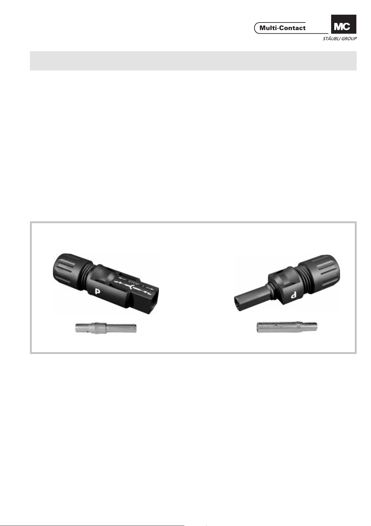
Conector macho PV de ensayo PV-KST4-P AU
Conector hembra PV de ensayo PV-KBT4-P AU
Índice
Instrucciones de seguridad ........................................................2
Herramientas necesarias ...........................................................3
Montaje .....................................................................................4
Preparación de los cables ..........................................................4
Engarce .....................................................................................4
Comprobación del montaje .......................................................5
Disposición del cable .................................................................5
Conector macho / Plug
MA000 (de_en)
MA260 (es_en)
Assembly instructions
Assembly instructions
PV test plug PV-KST4-P AU
PV test socket PV-KBT4-P AU
Content
Safety Instructions ......................................................................2
Tools required ............................................................................3
Assembly ...................................................................................4
Cable preparation ......................................................................4
Crimping ....................................................................................4
Assembly control .......................................................................5
Cable routing .............................................................................5
Conector hembra / Socket
PV-KST3-P AU PV-KBT3-P AU
www.multi-contact.com 1 / 8
Page 2
Advanced Contact Technology
Instrucciones de seguridad Safety Instructions
Sólo personal adecuadamente cualifi cado y especialistas for-
mados podran realizar el montaje y la instalación de los productos teniendo en cuenta todas las regulaciones de seguridad aplicables.
Multi-Contact (MC) no se responsabiliza ante el incumplimiento de estas advertencias
Utilice sólo los componentes y herrmientas indicadas por MC.
No se desvíe de los procedimientos de preparación y montaje
aquí descritos, en caso de una manipulación inadecuada no
se podrá garantizar la seguridad ni la conformidad con los datos técnicos. No modifi que el prodcuto en ningún caso.
Los conectores no fabricados por MC que se pueden conectar
con elementos MC, a veces denominados por los fabricantes
como „compatibles con MC“ no cumplen con los requisitos
para una conexión eléctrica segura y estable a largo plazo.
No pueden conectarse con elementos MC por motivos de seguridad. Por tanto, MC no se responsabilizará de los daños
surgidos por la conexión de conectores no autorizados por
MC con elementos MC.
Los trabajos aquí descritos no pueden ejecutarse
en piezas conectadas a la red y con tensión.
El producto fi nal debe proporcionar protección al
usuario frente a una descarga eléctrica.
Los conectores no pueden separarse estando cargados. Se permite la conexión y desconexión con
tensión.
Los conectores son impermeables según el tipo de
protección IP. Pero no están indicados para un largo
uso bajo agua. No coloque los conectores directamente sobre una cubierta.
Se deben proteger ante la humedad y suciedad los
conectores no conectados con una tapa de cierre
(MC4 nº de artículo 32.0716 para bornes y 32.0717
para enchufes). No se pueden conectar conectores
sucios.
El conector no debe someterse nunca a una tracción
mecánica duradera. El cable debe fi jarse con bridas.
MC recomienda no utilizar cables de PVC ni cables
no galvanizados del tipo H07RN-F.
Los conectores de comprobación PV están diseña-
dos para su aplicación en el interior (laboratorios,
fábricas).
The products may be assembled and installed only by suitably
qualifi ed and trained specialists with due observance of all ap-
plicable safety regulations.
Multi-Contact (MC) declines any liability in the event of failure
to observe these warnings.
Use only the components and tools specifi ed by MC. Do not
deviate from the preparation and assembly procedures described here, since in this event, in the event of self-assembly, no
guarantee can be given as to safety or conformity with the
technical data. Do not modify the product in any way.
Connectors not made by MC which can be mated with MC
elements and in some cases are also described as ”MC-compatible” do not conform to the requirements for safe electrical connection with long-term stability, and for safety reasons
must not be plugged together with MC elements. MC can
therefore accept no liability for damage which occurs as a result of mating these connectors which lack MC approval with
MC elements.
The work described here must not be carried out
on live or load-carrying parts.
Protection from electric shock must be assured by
the end product and its user
The plug connections must not be disconnected
under load. Plugging and unplugging when live is
permitted.
The plug connectors are watertight in accordance
with IP protection class. However, they are not
suitable for continuous operation under water. Do
not place the plug connectors directly on the roof
membrane.
Unmated plug connectors must be protected from
moisture and dirt with a sealing cap (MC4 Article
No. 32.0716 for sockets and 32.0717 for plugs). The
male and female parts must not be plugged together
when soiled.
The plug connection must not be subjected to conti-
nuous mechanical tension. The cable should be fi xed
with cable binders.
MC does not recommend the use of either PVC
cables or untinned cables of type H07RN-F.
PV test plugs are intended primarily for indoor use
(test laboratories, production halls).
Encontrará más detalles técnicos en el catálogo del
producto.
For further technical data please see the product
catalogue.
Explicación de los símbolos Explanation of the symbols
Advertencia de voltajes peligrosos
Advertencia de área de peligro Warning of a hazard area
Sugerencia o consejo útil Useful hint or tip
2 / 8 www.multi-contact.com
Warning of dangerous voltages
Page 3

Advanced Contact Technology
Herramientas necesarias Tools required
(ill. 1)
Alicate pela-cables PV-AZM... y destornillador hexagonal 2,5 mm.
Sección del cable:1,5 / 2,5 / 4 / 6 mm²
Tipo: PV-AZM-1.5/6
No. de código: 32.6027-156
1
(ill. 1)
Stripping pliers PV-AZM... incl.
built-in wire stripping blade as well as
hexagonal screwdriver A/F 2,5.
Conductor cross section:
1,5 / 2,5 / 4 / 6 mm²
Type: PV-AZM-1.5/6
Order No.: 32.6027-156
(ill. 2)
Alicates de engarce PV-CZM... con
posicionador y matriz de engarce
integrada.
Sección del cable: 2,5 / 4 / 6mm²
(14/12/10 AWG)
Tipo: PV-CZM-16100
No. de código: 32.6020-16100A
Matrices de engarce intercambiables
con llave hexagonal de 2,5mm.
Tipo: PV-ES-CZM-16100
2
No. de código: 32.6021-16100
(ill. 3)
Llave fi ja PV-MS,
1 N° de código = 2 piezas
No. de código: 32.6024
3
(ill. 4)
Llave para apretar PV-WZ-AD/GWD
No. de código: 32.6006
4
(ill. 5)
Llave para fi jar PV-SSE-AD4
No. de código: 32.6026
5
(ill. 2)
Crimping tool MC3 PV-CZM... incl.
locator and built-in crimping insert.
Crimping range: 2,5 / 4 / 6mm²
(14/12/10 AWG)
Type: PV-CZM-16100
Order No.: 32.6020-16100A
Interchangeable crimping inserts incl.
hexagonal screwdriver A/F 2,5.
Type: PV-ES-CZM-16100
Order No.: 32.6021-16100
(ill. 3)
Open-end spanner PV-MS
1 Set = 2 pieces
Order No.: 32.6024
(ill. 4)
PV-WZ-AD/GWD socket wrench
insert to tighten
Order No.: 32.6006
(ill. 5)
PV-SSE-AD4 socket wrench insert to
secure
Order No.: 32.6026
(ill. 6)
Clavija de ensayo PV-PST
6
No. de código: 32.6028
(ill. 7)
CHROM - VANA DIUM
15
Llave inglesa 15mm
7
(ill. 8)
Llave dinamométrica 12mm
8
www.multi-contact.com 3 / 8
(ill. 6)
Test plug PV-PST
Order No.: 32.6028
(ill. 7)
Open-end spanner A/F 15mm
(ill. 8)
Torque screwdriver A/F 12mm
Page 4

Advanced Contact Technology
Montaje Assembly
Preparación de los cables Cable preparation
L= 6 - 7,5mm
Pueden conectarse cables de clase 5
o 6.
Nota:
No utilice cables oxidados o sin
revestimiento. Es aconsejable utilizar
conductores estañados. Los cables
solares AII MC cuentan con conductores estañados de alta calidad.
(ill. 9)
Se pueden conectar cables con sec-
AA
ciones de 2,5 – 4mm² y 14 – 10 AWG.
Atención
Compruebe que el diámetro exterior del cable corresponde al de
los pines macho y hembra.
Tipo: A = Ø del passacables
PV-K...T4/...6I: 3 – 6 mm
9
PV-K...T4/...6II: 5.5 – 9 mm
(ill. 10)
Pele el cable
Quite de 6 a 7,5 mm de aislante del
extremo del cable.
Atención:
Tenga cuidado de no cortar
ningún hilo.
Cables with a strand construction of
classes 5 and 6 can be connected.
Note:
Use no uncoated or already
oxidised conductors. It is advantage
to use tinned conductors. All MC
solar cables have high-quality, tinned
conductors.
(ill. 9)
Cables with conductor cross section
from 2,5 - 4mm² resp. from 14 - 10
AWG can be connected.
Attention
Take care that the type of test
plug or test socket matches the
cable diameter (A).
Type: A = Ø range of cable
PV-K...T4/...6I: 3 – 6 mm
PV-K...T4/...6II: 5.5 – 9 mm
(ill. 10)
Strip cable insulation
Remove 6 to 7,5 mm of insulation
from the end of the cable.
1)
Attention
Take care not to cut individual
strands.
S
max. 1 mm
Nota:
Para obtener instrucciones sobre
10
cómo utilizar los alicates pela cables
PV-AZM y cómo cambiar las hojas de
corte, consulte las instrucciones de
operación MA267 en www.multicontact.com
Engarce Crimping
Importante
Utilice solo la herramienta de inserción MC3 PV-ES-CZM-16100!
(ill. 11)
1. Coloque la parte metálica del pin
macho o hembra en la guía para la
sección de cable correspondiente.
2. Inserte el cable en la ranura de engarce hasta el fi nal y fíjelo.
11
(ill. 12)
Atención:
Todos los conductores deben ser
introducidos deben ser introducidos en el orifi cio S dejando una
distancia máxima visible de 1mm
3. Cierre completamente la herramienta de engarce.
12
1)
For directions on the operation of stripping pliers PV-AZM... and changing blade
sets, see operating instruction MA267 at
www.multi-contact.com
Important
Use only the MC3 crimp insert
PV-ES-CZM-16100!
(ill. 11)
1. Place the metal part of the female
or male coupler in the guide for the
appropriate cross section.
2. Insert the wire into the crimping
sleeve as far as it will go. Hold the
wire in place in the sleeve.
(ill. 12)
Attention
All strands of the wires must be
correctly inserted into the borehole and visible in sight hole S.
The max. distance of 1mm must
not be exceeded.
3. Completely close the crimping tool.
4 / 8 www.multi-contact.com
Page 5

Advanced Contact Technology
(ill. 13)
4 . Verifi que la crimpadora en forma
visual.
Nota:
Instrucciones de montaje de las
13
herramientas de engarce, mirar
MA251, www.multi-contact.com
(ill. 13)
4. Visually check the crimp.
Note:
to the operation of the crimping
pliers, see MA251, www.multicontact.com
Comprobación del montaje Assembly control
(ill. 14)
Inserte el contacto engarzado en el
aislador del pin macho o hembra
hasta que se encaje haciendo un
clic. Tire suavemente del cable para
comprobar que la parte metálica esté
correctamente acoplada.
14
(ill. 15)
Introduzca la clavija de ensayo por su
cara apropiada en la conexión hembra
hasta llegar a fondo. Si el contacto
está correctamente montado, la
marca blanca estará permanentemente visible.
(ill. 14)
Insert the crimped-on contact into the
insulator of the male or female coupler
until it clicks into place. Pull gently on
the lead to check that the metal part is
correctly engaged.
(ill. 15)
Insert the appropriate end of the test
pin into the male or female coupler as
far as it will go. If the contact is correctly located, the white mark on the
test pin must still be visible.
marco blanca
15
(ill. 16)
Apriete el pasacables con la herramientas PV-MS
o
16
(ill. 17)
Apretar el prensa-estopas con las
herramientas PV-WZ-AD/GWD y PV-
SSE-AD4.
17
(ill. 16)
Screw up the cable gland hand-tight
with the tools PV-MS
or
(ill. 17)
Tighten the cable gland with the tools
PVWZ-AD/GWD and PVSSE-AD4.
Disposición del cable Cable routing
Referir a la especifi cación del fabrican-
te del cable para el radio de curvatura.
Refer to cable manufactures specifi ca-
ton for minimum bending radius.
www.multi-contact.com 5 / 8
Page 6

Advanced Contact Technology
Notas / Notes:
6 / 8 www.multi-contact.com
Page 7

Advanced Contact Technology
Notas / Notes:
www.multi-contact.com 7 / 8
Page 8

Advanced Contact Technology
Notas / Notes:
Fabricante/Producer:
Multi-Contact AG
Stockbrunnenrain 8
CH – 4123 Allschwil
Tel. +41/61/306 55 55
Fax +41/61/306 55 56
mail basel@multi-contact.com
www.multi-contact.com
© by Multi-Contact AG, Switzerland – MA260 – 02.2011, Index b, Global Communications – Sujeto a modifi caciones / Subject to alterations
 Loading...