

Page 1
Advanced Contact Technology
MA234 (de_en_fr)
Montageanleitung
Stift- und Buchsengehäuse
FL3-INTERBUS
BeiderBenutzungvonanderenalsvon
MC angegebenen Einzelteilen und Werkzeugen, sowie bei Abweichung der hier
beschriebenen Vorgänge zur Vorbereitung
und Montage, kann bei der Selbstkonfektionierung weder die Sicherheit, noch die
Einhaltung der technischen Daten
gewährleistetwerden.
Zum Schutz vor einem elektrischen
Schlag müssen die Bauteile bei der Montage
oder Demontage immer allseitig von der
Stromversorgung getrennt sein.
Das Stecken und Trennen von Steckverbindungen hat generell in stromlosem
Zustandzuerfolgen.
Technische Daten und vorkonfektionierte Bauteile siehe MC Katalog B
Docking .
line
MA234 (de_en_fr)
Assembly instructions
Pin- and socket housing
FL3-INTERBUS
The use of parts and tools otherthan
those stated by MC or disregarding these
preparationinstructions,canhaveaneffecton
safety and quality. Therefore, technical data
cannotbeguaranteed.
For protection against electric shock,
parts must be isolated from the power supply
whilebeingassembledordisassembled.
Connectors may not be connected or
disconnectedunderload.
Seethe MC catalogueBDocking for
technicaldataandassembledparts.
line
MA234 (de_en_fr)
Instructions de montage
Boîtier mâle et femelle
FL3-INTERBUS
Lors d'une confection personnelle, si
des composants et des outils différents de
ceux prescrits par MC sont utilisés, si en outre les instructions de montage ci-après ne
sont pas strictement appliquées, le respect
des règles élémentaires de sécurité, des caractéristiquestechniquesindiquées, ne saurait être garanti.
En vue de garantir une protection contre les chocs électriques, il est indispensable
de réaliser les opérations de montage et de
démontage hors tension, en veillant à déconnecter les différents composants de
toutealimentationélectrique.
Enrèglegénérale,ilnefautpasembrocher ou débrocher un connecteur sous
charge.
Caratéristiques techniques et pièces
constituantes: consulter le catalogue B
Docking .
line
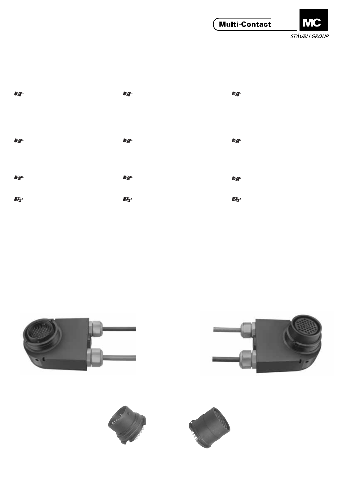
Auswechseln der Kontaktgehäuse
Replacement of contact
housings
Im Reparaturfall kann das Stiftgehäuse- (1) bzw. BuchsengehäuseVorderteil (2) ausgetauscht werden.
In the event of damage, the front part
of pin housing (1) or socket housing
(2) can be replaced.
Stiftgehäuse / Pin housing / Boîtier mâle
FL3-INTERBUS-SG
18.0920-100
Remplacement des
boîtiers de contact
En cas de réparation, le boîtier avant
mâle (1) ou femelle (2) peut être
remplacé.
Buchsengehäuse / Socket housing / Boîtier femelle
FL3-INTERBUS-BG
18.0921-100
Stiftgehäuse Vorderteil
Front part of pin housing
Boîtier avant mâle
FL3-BUS-VT-36+PE-S
18.6920
www.multi-contact.com
Buchsengehäuse-Vorderteil
Front part of socket housing
Boîtier avant femelle
FL3-BUS-VT-36+PE-B
18.6921
1/8
Page 2

Advanced Contact Technology
Notwendiges Werkzeug Tools required Outillage nécessaire
(ill.1)
I
II
6
3
Nr. Typ Bestell-Nr. Bezeichnung
No. Type Order No. Designation
No. Type No. de Cde Désignation
FL3-WZ 18.0946 Demontagewerkzeug / Extraction tool / Outil de démontage
3
FL3-MSR BS 18.0947 Montage-Stützring / Support ring / Bague de support
4
FL3-M-RG 18.0948 Montagering / Assembly ring / Bague de montage
5
- - Schraubendreher / Screwdriver / Tournevis
6
- - Sechskant-Schraubendreher SW2 / Hex key wrench A/F 2 / Clé à 6 pans 2mm
7
F
H
Demontagewerkzeug
Extraction tool
3 FL3-WZ
Outil de démontage
4
Montage-Stützring
Support ring
4 FL3-MSR BS
Bague de support
5
7
7
Ø6,6mm
Montagering
Assembly ring
5 FL3-M-RG
Bague de montage
Schraubendreher als Drehhebel
Screwdriver as lever arm
6
Tournevis à utiliser comme bras de levier
8
1/2
Haltering
Fixing ring
9
Bague de fixation
Stiftgehäuse- bzw. Buchsengehäuse-Vorderteil
Front part of pin or socket housing
Boîtier avant mâle ou femelle
I
II
4
ill.2
(ill.2)
Gewindestift (8) herausschrau-ben mittels Sechskant-Schraubendreher (7).
2/8
(ill. 2)
Unscrew setscrew (8) using hex
key wrench (7).
www.multi-contact.com
(ill.2)
Dévisser la vis sans tête (8) avec
la clé à 6 pans (7).
Page 3

Advanced Contact Technology
Den Haltering (9) herausschrau-ben
mittels Montagering (5) und dem
Schraubendreher (6) als Drehhebel.
An die Stelle des Halterings (9) den
Montage-Stützring (4) setzen. Dieser
hat 2 Stützflächen I und II. Fläche I ist
für die Demontage des StiftgehäuseVorderteils, Fläche II für die
Demontage des BuchsengehäuseVorderteils. Danach das
Demontagewerkzeug (3) am Stift- (1)
bzw. Buchsengehäuse-Vorderteil (2) in
den vorgesehenen Bohrungen
ansetzen. Die Schenkel des
Montagewerkzeuges
zusammendrücken und gleich-zeitig in
Richtung FH drücken und so das Stift(1) bzw. Buchsenge-häuse-Vorderteil
(2) heraushebeln.
Das neue Stift- (1) bzw. Buchsengehäuse-Vorderteil (2) lagerichtig (Nut
passend zum Führungsstift) einbauen
(von Hand eindrücken). Es ist
unbedingt darauf zu achten, dass das
Stift- bzw. Buchsenge-häusevorderteil
in das richtige, entsprechende
Gehäuse (siehe Aufschrift) eingesetzt
wird. Halte-ring (9) mit Hilfe des
Montage-rings (5) einschrauben. Zum
Schluss den Gewindestift (8) zur
Fixierung des Halterings (9) mittels
Sechskant-Schraubendre-her (7)
einschrauben.
Unscrew the fixing ring (9) by means
of the assembly ring (5), using the
screwdriver (6) as a lever.
Replace the fixing ring with (9) with
the support ring (4).
This has two supporting surfaces I
and II. Surface I is for removing the
front part of the pin housing, and
surface II for removing the front part
of the socket housing. Then engage
the extraction tool (3) in the holes
provided in the front part of the pin (1)
or socket (2) housing. Press together
the arms of the assembly tool and at
the same time push in direction FH so
as to lever out the front part of the pin
(1) or socket (2) housing.
Fit the new pin (1) or socket (2)
housing front part in its correct
position (slot fitting to the iron pin). It
is essential to ensure that the front
part of the pin or socket housing is
inserted in the correct housing (see
label). Screw-in the locking ring
(9)with help of the assembly ring (5).
Finally screw in the setscrew (8) to fix
the locking ring (9) using the hex key
wrench (7).
Dévisser la bague de fixation (9) à
l'aide de la bague de montage (5) et
du tournevis (6) utilisé comme bras de
levier. Mettre la bague de support (4)
à la place de la bague de fixation (9).
Celle-ci possède 2 surfaces d'appui I
et II. La surface I est destinée au
démontage du boîtier avant mâle, la
surface II au démontage du boîtier
avant femelle. Placer ensuite l'outil de
démontage (3) dans les trous prévus
du boîtier avant mâle (1) ou femelle
(2). Serrer les branches de l'outil de
démontage tout en poussant dans la
direction FH pour extraire le boîtier
avant mâle (1) ou femelle (2).
Positionner correctement le nouveau
boîtier avant mâle (1) ou femelle (2)
(petite rainure en haut) (l'enfoncer à la
main). Il faut impérativement veiller à
mettre en place le boîtier avant mâle
ou femelle dans le boîtier correspondant (voir inscription).Visser la
bague de fixation (9) avec l'aide de la
bague de montage (5). Enfin, poser la
vis sans tête (8) avec la clé à 6 pans
(7) pour fixer la bague de fixation (9).
Anschliessen weiterer Kontakte Connecting of further contacts Connexions d'autres contacts
Der FL3-INTERBUS Steckver-binder
ist von Multi-Contact schon mit den
Signal- und Versorgungsleitungen für
das Interbussystem vorbereitet.
Die Belegung ist in der Tab.1, Seite
5/8 ersichtlich.
Neben den Bus- und SchirmKontakten sind im Steckverbinder
noch weitere 9, frei verfügbare
Kontakte vorgesehen, (z.B. zur
Sekundärkreisüberwachung oder
Konstantstromregelung etc.) Von
diesen 9 Kontakten sind 4 ge-schirmt
(siehe Tab.1, Seite 5/8).
The FL-3 INTERBUS plug connector is
already prepared by Multi-Contact
with the signal and supply leads for
the interbus system. The contact
assignment is shown in Tab.1, page
5/8. In addition to the bus and
shielding contacts, a further 9 freely
vacant contacts are provided in the
plug connector (e.g. for secondary
circuit monitoring or constant current
regulation etc.) 4 of these 9 contacts
are shielded (see Tab.1, page 5/8).
Le connecteur FL3-INTERBUS est
déjà préparé par Multi-Contact pour le
système Interbus avec les lignes de
signalisation et d'alimentation.
L'affectation des broches est indiquée
dans le Tab. 1, page 5/8. Outre les
contacts de bus et de blindage, il est
pré-vu dans le connecteur 9 autres
contacts dont l'utilisateur peut
disposer librement (p. ex. pour
surveillance de circuit secondaire ou
régulation de courant constant, etc.).
Sur ces 9 contacts, 4 sont blindés
(voir Tab.1, page 5/8).
www.multi-contact.com
3/8
Page 4

Advanced Contact Technology
Notwendiges Werkzeug Tools required Outillage nécessaire
Sechskant-Schraubendreher SW2,5
Hex key wrench A/F 2,5
Clé à 6 pans 2,5mm
Schlitzschraubendreher 0,4x2,0
Slot-head screwdriver 0,4x2,0
Tournevis 0,4x2,0
Bestell-Nr. / Order No. / No. de Cde: 18.0950 Bestell-Nr. / Order No. / No. de Cde: 18.0951
Vorbereiten der Signalleitung Preparation of
signal line
ill.3
max. 9 x 0,14 - 0,5mm
Kreuzschraubendreher Gr. 1
Cross head screwdriver Size 1
Tournevis cruciforme Gr. 1
Schlitzschraubendreher 0,6x3,5
Slot-head screwdriver
Tournevis
0,6x3,5
Préparation du câble de signal
2
0,6x3,5
(ill.4)
Kabel und Einzelleiter auf die
angegebenen Masse abisolieren.
ill.4
(ill.4)
Strip cable and wires to the
indicated dimensions
SW2,5
A/F 2,5
2,5mm
4
ill.5
(ill.4)
Dénuder le câble et les
conducteurs sur la longueur
indiquée.
(ill.5)
Deckel (4) des Stift- bzw.
Buchsengehäuses mittels
Sechskant-Schraubendreher
SW2,5 lösen und abheben.
4/8
(ill.5)
Release cover (4) of the socket
housing using an A/F 2,5 hex key
wrench and lift off.
www.multi-contact.com
(ill.5)
Détacher le couvercle (4) du
boîtier mâle ou femelle au
moyen de la clé à 6 pans de
2,5mm et l'enlever.
Page 5

Advanced Contact Technology
1
2
2
(1Nm)
Kreuzschlitzschraubendreher
Cross-head screwdriver
Tournevis cruciforme
(2,5Nm)
3
(3,5Nm)
2
(1Nm)
(1Nm)
2
Schlitzschraubendreher 0,4x2,0
Slot-head screwdriver 0,4x2,0
Tournevis 0,4x2,0
ill.6
3
3
3
4
4
Schlitzschraubendreher 0,6x3,5
Slot-head screwdriver 0,6x3,5
Tournevis 0,6x3,5
4
4
Tab. 1
Klemmen / Clamp / Borne No.
Interbus
LWL
Interbus
Cu
Bemessungsstrom (A)
Rated current (A)
Intensité assignée (A)
Bemessungsspannung
Rated voltage (VDC/VAC)
Tension assignée
1) L = Leer
2) L/S = Leer (geschirmt)
3) Schirm
(VDC/VAC)
(VDC/VAC)
123456789101112131415161718192021
(SKÜ 1)
(SKÜ 2)
(KSR 1)
2)
L/S
(KSR 1)
2)
L/S
(KSR 2)
2)
L/S
(KSR 2)
2)
L/S
D0
D0
/D0
/D0
DI
DI
/DI
/DI
COM
COM
3)
3)
+24 V Aktor
GND Aktor
PE
+24 V Aktor
GND Aktor
PE
+24 V Sensor
GND Sensor
PE
+24 V Sensor
GND Sensor
PE
2)
1)
1)
1)
1)
L
L
L
1)
1)
L
1)
L
L
1)
L
L
1)
1)
L
L
L/S
(SKÜ 1)
2)
L/S
2)
L/S
(SKÜ 2)
2)
L/S
16 16 16 10 10 10 1 1 1 1 1 1 1 1 1 1 1 1 1 1 1
33 / 70
33 / 70
33 / 70
33 / 70
33 / 70
33 / 70
33 / 70
33 / 70
33 / 70
33 / 70
33 / 70
33 / 70
33 / 70
33 / 70
33 / 70
33 / 70
33 / 70
33 / 70
33 / 70
33 / 70
1) L = Vacant
2) L/S = Vacant (shielded)
3) Shield
www.multi-contact.com
1) L = Vacant
2) L/S = Vacant (blindé)
3) Blindage
33 / 70
5/8
Page 6

Advanced Contact Technology
Leiterplatte ausbauen Removing the printed circuit
board
Vor Entfernung der Leiterplatte muss
das Stift- (1) bzw. Buchsen-gehäuseVorderteil (2) entfernt werden (siehe
Seite 2/8, Aus-wechseln der
Kontaktgehäuse).
Deckel abschrauben, siehe ill.5, Seite
4/8.
4 Linsen-Kreuzschlitzschrauben (2) mit
Kreuzschlitzschrauben-dreher lösen.
Leiterplatte vor-sichtig abheben und
umklappen (siehe ill.6, Seite 5/8).
Verschlussstopfen (1) herausschrauben und vorbereitetes
Signalkabel (ill.4, Seite 4/8) mit
Kabelverschraubung anstelle des
Verschlussstopfens verschrau-ben.
(Einschraubdrehmoment
Verschraubung in Gehäuse: 3,5Nm;
Anzugsdrehmoment der
Überwurfmutter: 2,5Nm).
Die Adern des neu eingeführten
Signalkabels mit den freien Klemmen
der Leiterplatte ver-binden. Es stehen
4 geschirmte (12-15) und 5
ungeschirmte (7-11) Kontakte zur
Verfügung.
Leiterplatte wieder zurückklap-pen. 4
Isolierhülsen (3), die in der Leiterplatte
verklebt sind, in die 4 Bohrungen (4)
einführen und mit
Kreutzschlitzschrauben (2), mit
Drehmoment max. 1Nm verschrauben. Danach den Deckel
montieren und festschrauben und das
Kontaktgehäuse wieder ein-setzen
(siehe Seite 3/8, Aus-wechseln der
Kontaktgehäuse).
Before removing the printed circuit
board, the front part of the pin (1) or
socket (2) housing must be removed
(see page 2/8, replacement of contact
housings). Unscrew cover, see ill.5,
page 4/8.
Unscrew 4 oval cross-head screws (2)
with cross-head screwdriver. Carefully
lift printed circuit board and hinge
back (see ill.6, page 5/8).
Unscrew blind plug (1) and screw in
the prepared signal cable (ill.6, page 4-
8) with cable gland in place of the
blind plug. (Torque for screwing gland
into housing: 3.5Nm; tightening
torque of cover nut: 2.5Nm).
Connect the conductors of th newly
inserted signal cable with the free
terminals of the printed circuit board.
4 shielded (12-15) and 5 unshielded
(7-11) contacts are available.
Hinge printed circuit board back to its
original position. Insert into the 4
holes the 4 insulating sleeves (3) that
are glued into the printed circuit board
and screw board in place with crosshead screws (2) to a torque of 1Nm
max. Then fit the lid and screw in
place, and put the contact housing
back in place (see page 3/8, replacing
the contact housing).
Démontage du circuit imprimé
Avant d'enlever le circuit imprimé, il
faut enlever le boîtier avant mâle (1)
ou femelle (2) (voir page 2/8,
Remplacement des boîtiers de
contact). Dévisser le couvercle, voir
ill.5, page 4/8.
Desserrer les 4 vis à tête cruci-forme
bombée (2) avec le tourne-vis
cruciforme. Lever et rabattre avec
précaution le circuit impri-mé (voir
ill.6, page 5/8). Dévisser le bouchon
de fermeture (1) et visser le câble de
signalisation préparé (ill.4, page 4/8)
avec le presse-étoupe à la place du
bouchon de fermeture. (Couple de
serrage du presse-étoupe dans le
boîtier: 3,5Nm; couple de serrage de
l'écrou: 2,5Nm).
Connecter les conducteurs du
nouveau câble de signalisation inséré
avec les bornes libres du circuit
imprimé. 4 contacts blindés (12-15) et
5 contacts non blindés (7-11) sont
disponibles.
Rabattre le circuit imprimé. Introduire
les 4 fourreaux isolants (3) qui sont
collées sur le circuit imprimé dans les
4 trous (4) et les visser avec les vis
crucifor-mes (2) à un couple de 1Nm
max. Remonter le couvercle et le
visser puis remettre en place le
boîtier de contact (voir page 3/8,
Remplacement des boîtiers de
contact).
6/8
www.multi-contact.com
Page 7

Advanced Contact Technology
Beispiel
Bohrplan
-0,5
+0,5
91
0
+0,1
62
Example
Drilling plan
12,5
Exemple
Plan de perçage
±0,1
II
Zylinderstift ø 3
Setscrew ø 3
Vis sans tête ø 3
II
Es müssen 2 Zentrierstifte
eingesetzt werden.
Zulässiger Winkelversatz
Stift- Buchsenseite
± 0,5°
Zulässige x-y Abweichung
von Stift- und Buchsenseite ± 0,2 mm
Ø3H7
Two centring pins are to be
used. Permissible angular
deviation of the pin and of
the socket sides ± 0,5°
Permissible x-y deviation
of the pin and the socket
sides ± 0,2 mm.
2 pions de centrage doivent
être installés. Déplacement
angulaire admissible entre la
fiche et la douille ± 0,5°
Déviation x-y admissible du
côté fiche et du côté douille
± 0,2 mm.
www.multi-contact.com
7/8
Page 8

Advanced Contact Technology
MA234 (de_en_fr)
8/8
Änderungen vorbehalten/Subject to alterations/Modifications sous réserve
Copyright by Multi-Contact AG, Switzerland / Docking / 11.2006 / Index b
www.multi-contact.com
line
 Loading...