

Page 1

Advanced Contact Technology
MA228 (de_en_fr)
Montageanleitung
TJSB150/..., TJSB 150+2/...
Anschlussstecker zur Adapterplatte für Primärkreissteckverbinder für Schweisstransformatoren
Typ J nach ISO 10656
Bei der Benutzung von anderen als von
MC angegebenen Einzelteilen und Werkzeugen, sowie bei Abweichung der hier beschriebenen Vorgänge zur Vorbereitung und
Montage, kann bei der Selbstkonfektionierung weder die Sicherheit, noch die Einhaltung der technischen Daten gewährleistet
werden.
Zum Schutz vor einem elektrischen
Schlag müssen die Bauteile bei der Montage
oder Demontage immer allseitig von der
Stromversorgunggetrenntsein.
Das Stecken und Trennen von Steckverbindungen hat generell in stromlosem Zustandzu erfolgen.
TechnischeDaten siehe FlyerARobo-
ticline.
MA228 (de_en_fr)
Assembly instructions
TJSB150/..., TJSB 150+2/...
Female plug for the adapter plate
for primary circuit connectors for
electric welding transformers type
J according to ISO 10656
If, during self assembly,parts and tools
other than those stated by MC are used or if
the preparation and assembly instructions
described here are disregarded then neither
the safety nor compliance with the technical
datacan beguaranteed.
For protection against electric shock,
parts must be isolated from the powersupply
whilebeing assembledor disassembled.
Connectors may not be connected or
disconnectedunder load.
Seetheflyer A Roboticline fortechnical
data.
MA228 (de_en_fr)
Instructions de montage
TJSB150/..., TJSB 150+2/...
Prise mobile pour plaque d'adaptation pour connecteurs pour circuit primaire de transformateurs
de soudure ISO 10656 de type J
Lors de l’assemblage, si des composants et des outils différents de ceux prescritsparMC étaient utilisés, si enoutreles instructions de montage ci-après n’étaient pas
strictement appliquées, ni la sécurité, ni la
conformité aux caractéristiques techniques
nesauraient êtregaranties.
En vue de garantir une protection contre les chocs électriques, il est indispensable
de réaliser les opérations de montage et de
démontage hors tension, en veillant à déconnecterlesdifférents composants detoutealimentationélectrique.
Enrèglegénérale, il nefaut pas embrocher ou débrocher un connecteur sous charge.
Caractéristiques techniques: voir plaquette ARoboticline.
ill.1
Delivery formLieferzustand
Etat de livraison
(ill.1)
Die Einheit wird in Einzelteilen geliefert (Kontakte separat).
(ill.1)
The unit is delivered in individual parts
(contacts separately).
www.multi-contact.com
(ill.1)
L'ensemble est livré en pièces détachées (contacts en sachet).
1/4
Page 2
Advanced Contact Technology
1
2
3
4
5
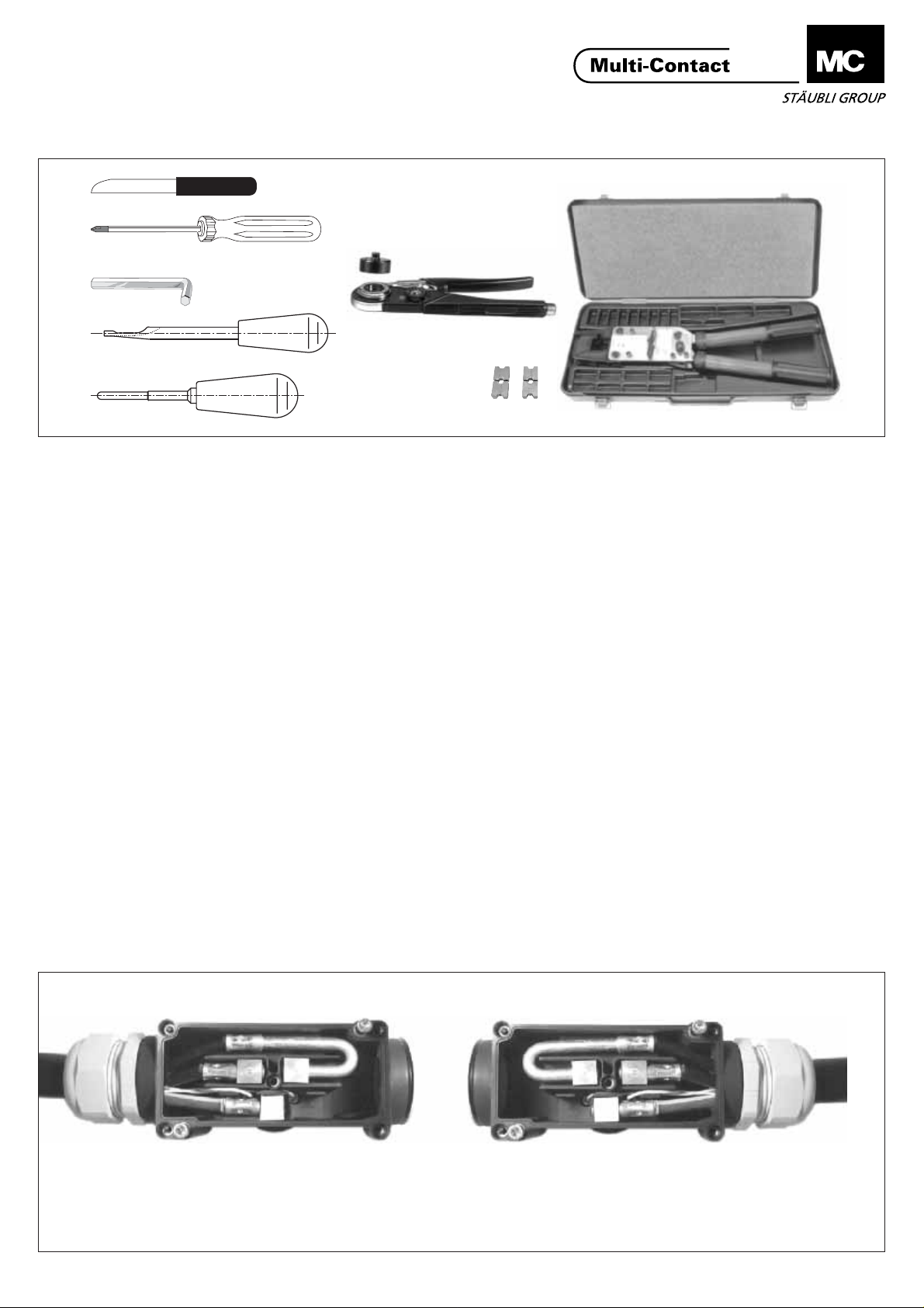
(ill.2)
1 Werkzeugzum Abisolieren
2 Kreuzschlitzschraubendreher
3 Sechskant-StiftschlüsselSW 4
4 EinsetzwerkzeugME-WZ1,5-2
Bestell-Nr.18.3003
5 Buchsenausbauwerkzeug
MBA-WZ6,Bestell-Nr.18.3017
6 Crimpzangefür Pilotkontakte
M-CZ,Bestell-Nr. 18.3800
7 Einsatz zuPos.6 für 0,5-1,5mm
MES-CZ1,5/2,Bestell-Nr.18.3802
8 Crimpzangefür Leistungskontakte
M-PZ-T2600, Bestell-Nr. 18.3710
(mitBox)
9 Einsatz zuPos.8 für 25mm
TB11-14,5,Bestell-Nr.18.3713
10 Einsatz zu Pos.8
TB9-13,Bestell-Nr.18.3712
für 35mm
2
2
Tools requiredNotwendiges Werkzeug
Outillage nécessaire
7
6
9
10
ill.2
(ill.2)
1 Toolto striptheinsulation
2 Philipss
3 Hexkey wrench4mm
4 Insertiontool ME-WZ1,5-2
OrderNo.18.3003
5 Extractiontool
MBA-WZ6,OrderNo. 18.3017
6 Crimpingpliers forpilotcontacts
2
M-CZ,OrderNo. 18.3800
7 Insertto pos.6 for0,5-1,5 mm
MES-CZ1,5/2,OrderNo. 18.3802
8 Crimpingpliers forpowercontacts
M-PZ-T2600, Order No. 18.3710
(boxincluded)
9 Insertto pos.8 für25 mm
TB11-14,5,OrderNo. 18.3713
10 Inserttopos.8 für35mm
TB9-13,OrderNo. 18.3712
crewdriver
2
2
2
(ill.2)
1 Outillagede dénudage
2 Tourneviscruciforme
3 Cléallen de 4mm
4 Outilde montageME-WZ1,5-2
5 Outilde démontage MBA-WZ6
6 Pinceà sertirpourcontacts
7 Matrice pour Pos.6 pour 0,5-
8 Pinceà sertirpourcontactsde
9 Matricepour pos.8 pour25 mm
10 MatricepourPos.8 pour 35 mm
8
No.deCde 18.3003
No.deCde 18.3017
pilotes
M-CZ,No.de Cde18.3800
2
mm
1,5
No. de Cde 18.3802
puissance
Cde18.3710(box inclus)
TB11-14,5,No.de Cde18.3713
TB9-13,No.de Cde18.3712
MES-CZ1,5/2,
M-PZ-T2600,No.de
2
2
Vorbereiten des Anschlusssteckers
(ill.3)
Alle 5 Deckelschrauben lösen, (sie
sind gegen das Herausfallen gesichert). Deckel abheben und die eingepackten Pilotkontakte herausnehmen.
Die Platzierung der Leistungskontakte
ist für einen Kabelausgang nach
rechts vorgesehen.
Kabelausgang links
Cable exit left
Sortie de câble à gauche
Preparation of the female plug
(Ill.3)
Unscrew all 5 captive screws of the
cover. Remove the cover and take out
the 2 pilot contacts.
The arrangement of the power
contacts is intended for a cable exit
on the right side.
Kabelausgang rechts
Cable exit right
Sortie de câble à droite
ill.3
Préparation de la prise
(ill.3)
Dévisser les 5 vis du couvercle,
(toutes les vis sont imperdables).
Enlever le couvercle de la prise et
sortir le sachet avec les contacts
pilotes (livrés avec la prise
TJSB+2/...). La prise se compose de
deux contacts de puissance droits,
2/4
www.multi-contact.com
Page 3

Advanced Contact Technology
Soll der Kabelausgang links sein,
genügt es die Kontakte zu drehen,
und U und V zu vertauschen. Der
gebogene Kontakt ist drehbar.
Anschliessend die
Kabelverschraubung (Pg36) und den
Blindstopfen jeweils auf die
gegenübeliegende Seite montieren.
Um die Kontakte von vorne aus der
Halterung zu drücken, das Buchsenausbauwerkzeug MBA-WZ6 benützen.
Für die Kabelerschraubung dürfen
nur Kunststoffausführungen verwendet werden. Werden in Ausnahmefällen trotzdem metallische Kabelverschraubungen verwendet,
sind diese in die Schutzmassnahme
miteinzubeziehen. Eine Kabelverschraubung gehört nicht zum Lieferumfang.
Vorbereiten des Kabels
Pilotkontakte
Pilot contacts
Contacts pilotes
If the cable exit should be on the left
side, the contacts must be turned and
the U and V contacts have to be
exchanged. (The bent contact is
turnable). Finally the screwed cable
gland (Pg36) and the dummy plug
must be screwed on the opposite
side. Use the extraction tool MBAWZ6 from the front side to push out
the contacts.
Only a plastic cable gland should be
used. Nevertheless, should a metal
cable gland in exceptional conditions be used, then it must be includedinthe safetymeasures.
(Cableglandis notincludedin
thedelivery).
Cable preparation
140
6
a + b
65
17
et d'un contact coudé, qui pivote
autour de son axe (contact tournant).
La prise est livrée dans une
configuration avec sortie de câble à
droite. En cas de sortie à gauche, il
suffit d'inverser les contacts U et V
(pivoter le contact coudé autour de
son axe). Inverser le bouchon et le
presse-étoupe Pg36. Pour extraire les
douilles de l'isolant, les repousser par
l'avant avec l'outil MBA-WZ6.
Utiliser uniquement des presseétoupes en matière plastique. En
cas d'utilisation extraordinaire d'un
presse-étoupe métallique, celui-ci
devraêtremis àlamasse.
Le presse-étoupe n'est pas inclus
danslalivraison.
Préparation du câble
ill.4
(ill.4)
Das Kabel durch die demontierte
Kabelverschraubung ziehen. Kabel
und Einzelleiter gemäss ill. 4
abisolieren.
Crimpen
Sichtloch
Inspection hole
Orifice de contrôle
V
17
U
90
(ill.4)
Slip the removed cable gland on the
cable. Strip the cable and single
conductors according to ill.4.
Crimping
ill.5
(ill.4)
Passer le câble par le presse-étoupe
préalablement démonté. Dégainer et
dénuder les câbles selon ill.4.
Sertissage
(ill.5)
Zum Crimpen der Leistungskontak- te
die Crimpzange M-PZ-T2600 und die
Einsätze TB11-14,5 (für 25 mm ) oder
TB9-13 (für 35mm ) verwenden und
2
2
für die Pilotkontakte die Crimpzange
M-CZ mit Einsatz MES-CZ1,5/2.
(ill.5)
For the power contacts use the
crimping pliers M-PZ-T2600 and the
2
inserts TB11-14,5 (for 25 ) and
TB9-13 (for 35 ). For the pilot
mm
mm
2
contacts use the crimping pliers M-CZ
and the insert
MES-CZ1,5/2.
www.multi-contact.com
(ill.5)
Pour les contacts de puissance
prendre la pince à sertissage
hexagonale M-PZ-T2600 qui sera
préalablement équipée des matrices
TB11-14,5 (pour 25mm ) et TB9-13
(pour 35mm ). Pour les contacts
2
2
pilotes, prendre la pince M-CZ et la
matrice MES-CZ1,5/2.
3/4
Page 4

Advanced Contact Technology
Die Leitung in die Crimphülse
einführen bis zum Anschlag.
Crimpvorgang ausführen und
gleichzeitig Leitung in axialer Richtung
in Crimphülse drücken. Die Leitung
muss vor und nach dem Crimpen im
Sichtloch sichtbar sein.
(ill.6)
Zuerst die Pilotkontakte (mit
angeschlossener Leitung)
Einsetzwerkzeug ME-WZ15,-2
Halterung stecken. Dann die
angecrimpten Leitungen in die Leitungsführungen legen und so bie-gen,
dass die Kontakte leicht einge-setzt
werden können. Die Kontakte in die
entsprechenden Halterungen stecken
bis zum Anschlag.
(ill.7)
Deckel auflegen und sicherstellen,
dass er richtig schliesst. (MC-Zei-chen
auf der gleichen Seite wie die
Ausbuchtung). Die 5 Schrauben mit
dem Kreuzschlitzschraubendreher
anziehen. Die Kabelverschraubung
über das Kabel schieben, bis sie am
Gewinde befestigt werden kann. Die
Mutter der Kabelverschraubung
festschrauben. Der Anschluss-stecker
ist jetzt betriebsbereit.
mit dem
in die
Insert wire into the contact crimping
sleeve to the end stop. During the
crimping operation, gently push the
wires into the sleeve. Wires must be
visible in the inspection hole before
and after crimping.
AssemblyMontage Montage
(ill.6)
Insert first the pilot contacts (with
connected cables) into their support
with the help of the insertion tool MEWZ1,5/2. Lay the crimped cables into
the cable guides and bend them in the
way that the contacts can be inserted
without force. Insert the power
contacts into the contact chambers
accordingly.
(ill.7)
Put on the cover (MC-Logo must be
on the same side like the bulg of
housing) and verify that its closed all
arround. Fasten the 5 screws with the
Philips . Slip the cable
gland over the cable until it can be
screwed on. Fasten the nut of cable
gland. The female plug is now ready
to use.
screwdriver
Introduire le conducteur dans le fût à
sertir jusqu'en butée. Sertir, tout en
maintenant le conducteur en position
dans le fût (pousser axialement). Le
conducteur doit être visible dans
l'orifice de contrôle après sertissage.
(ill.6)
Monter d'abord les contacts pilotes
dans l'isolant avec l'outil MEWZ1,5/2.
contacts pilotes s'il n'y a pas lieu
de les utiliser
sertis dans les passages de câble de
l'isolant en veillant à bien positionner
les contacts de puissance. Les
pousser dans leurs logements
respectifs jusqu'à encliquetage.
(ill.7)
Remonter le couvercle et vérifier sa
fermeture correcte (logo MC en face
du bossage). S'il y lieu, repousser
correctement les contacts dans
l'isolant. Serrer les 5 vis à l'aide du
tournevis. Remonter le presse-étoupe
en repoussant le câble, pour que le
joint d'étanchéité du presse-étoupe
fasse effet. Serrer correctement
l'écrou du presse-étoupe.
ainsi montée est prête à l'emploi.
Ne pas monter les
. Enfiler les câbles
La prise
ill.6
MC
Ausbuchtung
Bulg
Bossage
(ill.8)
Nach dem Stecken auf die
Adapterplatte des Transformators,
den Anschlussstecker mit den 2 6kant Schrauben fixieren.
ill.8
ill.7
(ill.8)
After connecting the adapter plate on
the transformer, fix the female plug
with the 2 screws.
(ill.8)
Lors du montage sur le
transformateur, utiliser les deux vis à
tête hexagonale pour verrouiller
l'ensemble sur son embase.
MA228 (de_en_fr)
4/4
Änderungen vorbehalten/Subject to alterations/Modifications sous réserve
Copyright by Multi-Contact AG, Switzerland / Robotic / 03.2004 / Index b
line
www.multi-contact.com
 Loading...