

Page 1
Advanced Contact Technology
MA227 (de_en_fr)
Montageanleitung
TJID150+2-S8/M8
Adapterplatte für
Primärkreissteckverbinder für
Schweisstransformatoren Typ J
nach ISO 10656
Bei der Benutzung von anderen als von
MC angegebenen Einzelteilen und Werkzeugen, sowie bei Abweichung der hier beschriebenen Vorgänge zur Vorbereitung und
Montage, kann bei der Selbstkonfektionierung weder die Sicherheit, noch die Einhaltung der technischen Daten gewährleistet
werden.
Zum Schutz vor einem elektrischen
Schlag müssen die Bauteile bei der Montage
oder Demontage immer allseitig von der
Stromversorgunggetrenntsein.
Das Stecken und Trennen von Steckverbindungen hat generell in stromlosem Zustandzu erfolgen.
TechnischeDaten siehe Flyer ARobo-
ticline.
MA227 (de_en_fr)
Assembly instructions
TJID150+2-S8/M8
Adapter plate for primary circuit
connectors for electric welding
transformers type J according to
ISO 10656
If, during self assembly,parts and tools
other than those stated by MC are used or if
the preparation and assembly instructions
described here are disregarded then neither
the safety nor compliance with the technical
datacan beguaranteed.
For protection against electric shock,
parts must be isolated from the powersupply
whilebeing assembledor disassembled.
Connectors may not be connected or
disconnectedunder load.
Seetheflyer A Roboticline fortechnical
data.
MA227 (de_en_fr)
Instructions de montage
TJID150+2-S8/M8
Plaque d'adaptation pour
connecteurs pour circuit primaire
de transformateurs de soudure
ISO 10656 de type J
Lors de l’assemblage, si des composants et des outils différents de ceux prescritsparMC étaient utilisés, si enoutreles instructions de montage ci-après n’étaient pas
strictement appliquées, ni la sécurité, ni la
conformité aux caractéristiques techniques
nesauraient êtregaranties.
En vue de garantir une protection contre les chocs électriques, il est indispensable
de réaliser les opérations de montage et de
démontage hors tension, en veillant à déconnecterlesdifférents composants detoutealimentationélectrique.
Enrèglegénérale, il nefaut pas embrocher ou débrocher un connecteur sous charge.
Caractéristiques techniques: voir plaquette ARoboticline.
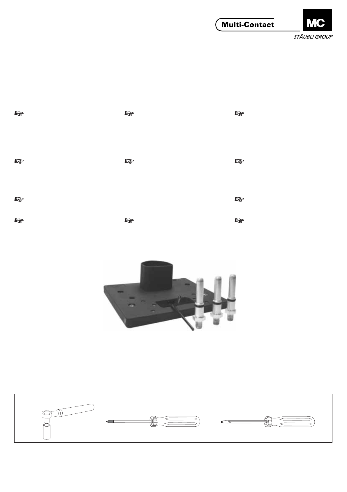
Lieferzustand
TJID150+2-S8/M8
ill.1
(ill.1)
Die Einheit wird in Einzelteilen geliefert (Kontakte separat). Die Pilotkontaktbuchsen sind verkabelt und montiert.
Notwendiges Werkzeug
Delivery form
(ill.1)
The unit is delivered in individual parts
(contacts separately). The pilot contacts (sockets) are assembled and
preconnected.
Tools required
Etat de livraison
(ill.1)
L'ensemble est livré en pièces détachées (contacts en sachet). Les contacts pilotes (douilles) précâblés sont
montés sur la plaque.
Outillage nécessaire
1
2
(ill.2)
1 Drehmomentschlüssel(6Nm)
2 6-kant-EinsatzzuPos.1, SW13mm
3 Kreuzschlitzschraubendreher 4mm
4 Schraubendreher4x150
3
ill.2
(ill.2)
1 Torquespanner(6Nm)
2 Boxspanner13mm
3 Screw driverforPhilipsscrews 4mm
4 Screwdriver4x150
www.multi-contact.com
4
(ill.2)
1 Clédynamométrique
2 Douillehexagonale13mm
3 Tourneviscruciformede4mm
4 Tournevisplatde4x150
1/4
Page 2
Advanced Contact Technology
Montage Assembly Montage
60 max.
28 mm
K
(ill.3)
Kontrollieren Sie:
- dass die Position der Anschlussgewinde am Transformator mit den
in der Zeichnung abgebildeten
Massen übereinstimmen.
- dass die Kunststoff-Trennwand (K)
nicht breiter als 60mm ist,
ansonsten muss sie gekürzt werden.
- dass die Beschriftungen nicht mehr
als 1 mm hoch sind, ansonsten
Höhe reduzieren.
3xM8
ill.3
(ill.3)
Check:
- that the positions of the threaded
connectors on the transformer are in
accordance with the dimensions
shown in the drawing.
- that the plastic dividing wall (K) is
not wider than 60 mm, otherwise it
must be shortened.
- that the labellings are not higher
than 1 mm, otherwise reduce
height.
22 mm
(ill.3)
Vérifier que:
- les entraxes de votre transformateur
sont conformes à la disposition type
J (voir croquis ci-dessus).
- la paroi de séparation en plastique
(K) ne dépasse pas une largeur de
60mm.
- les inscriptions ne dépasse pas
1mm de hauteur.
Si nécessaire, couper l'excès de
matière.
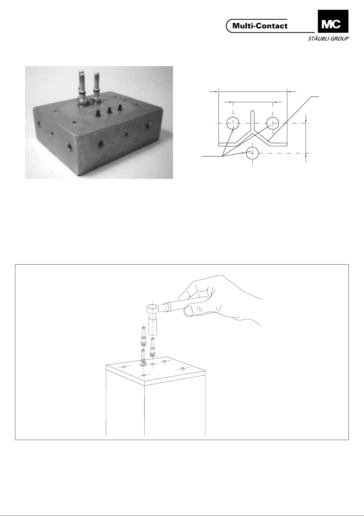
(ill.4)
Die 3 Ø 8 mm Stifte von Hand in die
Gewindebohrungen einschrauben und
mit dem Drehmomentschlüssel und
dem SW13 Einsatz anziehen.
Anzugsdrehmoment: 6 Nm.
2/4
ill.4
(Ill.4)
Screw the 3 Ø 8 mm pins by hand
into the threads and tighten with the
torque spanner and the 13 mm insert.
Tightening torque: 6 Nm
www.multi-contact.com
(ill.4)
Visser à la main les 3 broches Ø 8mm
dans les taraudages M8 en attente
sur le transformateur. Effectuer le
serrage final avec la clé dynamométrique et la douille de 13 mm au couple de 6 Nm.
Page 3

Advanced Contact Technology
ill.5
(ill.5)
Die Adapterplatte nach den
angeschraubten Stiften ausrichten
und die Anschlussleitungen der
Transformatorsteuerung durch die
Öffnung ziehen. Vorsicht beim
Auflegen der Platte die Gummiringe
der Stifte nicht verletzen. Die 4
unverlierbaren Schrauben mit dem
Kreuzschlitzschraubendreher
anziehen.
Hinweis:
Die Masse für die Position der 4 Befestigungsschrauben von Adapterplatte TJID... entsprechen der ISO
10656, Transformator Type “J”
(118x52 ±0,5mm).
(Ill.5)
Orientate the adapter plate towards
the screwed pins and insert the
control and transformer cables
through the opening of the plate.
Take care to the plastic rings on the
pins. Screw-on the adapter plate with
the 4 captive screws using the Philips
screwdriver.
Note:
The positioning dimensions of the 4
mounting screws the adapter plate
TJID... are according to ISO 10656,
transformer type “J”
(118x52 ±0,5mm).
(ill.5)
Prendre la plaque d'adaptation, bien
repérer le sens par rapport aux
broches vissées. Monter la plaque
d'adaptation, en prenant garde à ne
pas détériorer les joints toriques des
broches.
Faire sortir de l'ouverture de la
plaque, les câbles de contrôle et les
sondes du transformateur.
Une fois la plaque d'adaptation en
place, serrer les 4 vis imperdables à
l'aide du tournevis cruciforme.
Note:
Les cotes de fixation sur le
transformateur de la plaque TJID
répondent aux spécifications de la
norme ISO 10656, Transformateur de
Type “J”
(118x52 ±0,5mm).
(ill.6)
Die Steuer- und Pilotkontaktleitungen
in der Busverteilerbox gemäss Ihrem
Installationsschema anschliessen. Die
Busverteilerbox auf die Adapterplatte
schrauben.
Die Befestigungsgewinde erlauben
eine Orientierung der Leitungsabgänge der Busverteilerbox nach den
Gegebenheiten der Schweisszange.
ill.6
(Ill.6)
Connect the control and pilot cables in
the bus distributor box. Screw the bus
distributor box onto the adapter panel.
The fixing points allows an orientation
of the cable exit of the bus distributor
box according to the different
assembly situations.
www.multi-contact.com
(ill.6)
Raccorder les câbles pilotes et de
contrôle au boîtier répartiteur M12
CNOMO ou auxiliaire sur le bornier
encastré, en respectant le schéma de
votre installation.
Fixer le boîtier CNOMO à l'aide des
vis. Les taraudages permettent d'orienter la sortie du boîtier répartiteur
en fonction de la configuration de la
pince de soudure.
3/4
Page 4

Advanced Contact Technology
Montagewinkel
Special bracket
Equerre spéciale
ill.7
(ill.7)
Option:
Bei ungünstigen Platzverhältnissen
besteht die Möglichkeit mit einem
speziellen Montagewinkel (bei MC
erhältlich) die Busverteilerbox um 90°
gedreht zu montieren.
(ill.7)
Option:
If there is not enough space, MC
offers a special bracket which allows
the bus distributor box to be mounted
turned around 90°
(ill.7)
Option:
Dans certains cas le montage à plat
du boîtier CNOMO est impossible
pour des raisons d'encombrement.
Par l'intermédiaire d'une équerre
spéciale vous pouvez fixer ce boîtier à
90°. N'hésitez pas à nous consulter
pour cette option.
MA227 (de_en_fr)
4/4
Änderungen vorbehalten/Subject to alterations/Modifications sous réserve
Copyright by Multi-Contact AG, Switzerland / Robotic / 10.2003 / Index b
www.multi-contact.com
line
 Loading...