

Page 1
Advanced Contact Technology
MA000 (de_en)
MA224 (es_en)
Montageanleitung
Instrucciones de uso
MA000 (de_en)
MA224 (es_en)
Assembly instructions
Operating instructions
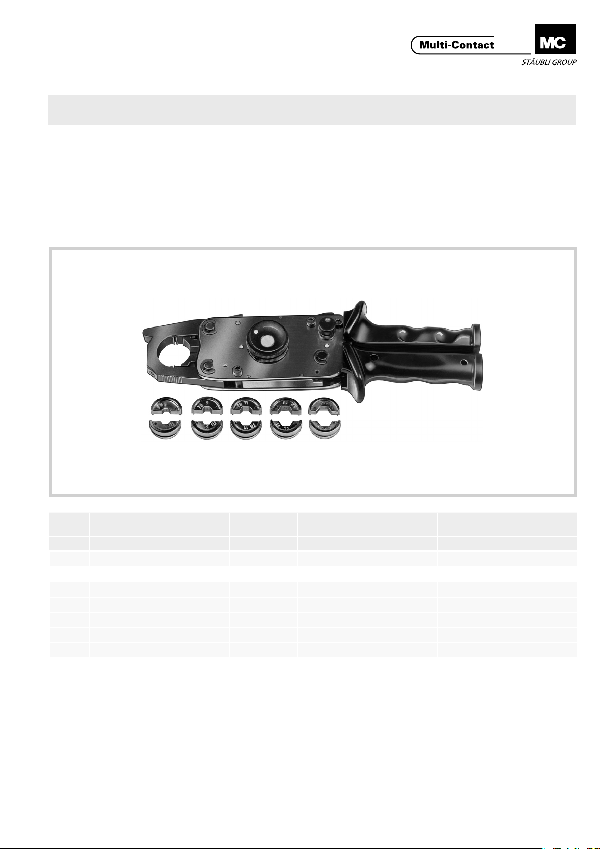
Alicates de engarce M-PZ13 Crimping pliers M-PZ13
Índice
Instrucciones de seguridad ........................................................2
Comprobación del funcionamiento de los alicates de engarce �5
Material de prueba ��������������������������������������������������������������������5
1
Content
Safety Instructions ......................................................................2
Function test of the crimping pliers ...........................................5
Test equipment ��������������������������������������������������������������������������5
2 3 4 65
Pos.
Tipo
Type
1 M-PZ13
1)
Casquillos de engarce para M-PZ13²
Código
Order No.
18�3700 -
)
/ Inserts to M-PZ13
Sección del conductor
for conductor cross section
mm² mm
2)
Dimensión de ensayo
Control dimension
2 MES-PZ-TB5/6 18�3701 6 -
3 MES-PZ-TB8/10 18�3702 10 6,3
4 MES-PZ-TB9/16 18�3703 16 7,3
5 MES-PZ-TB11/25 18�3704 25 8,8
6 MES-PZ-TB13/35 18�3705 35 10,2
1)
Alicates de engarce sin casquillos
2)
Pedir los casquillos por separado
www.multi-contact.com 1 / 8
1)
Crimping pliers without inserts
2)
Inserts to order separately
Page 2

Advanced Contact Technology
Instrucciones de seguridad Safety instructions
Sólo personal adecuadamente cualicado y especialistas formados podran realizar el montaje y la instalación de los productos teniendo en cuenta todas las regulaciones de seguridad aplicables�
Multi-Contact (MC) no se responsabiliza ante el incumplimiento de estas advertencias�
Utilice sólo los componentes y herrmientas indicadas por MC�
No se desvíe de los procedimientos de preparación y montaje
aquí descritos, en caso de una manipulación inadecuada no
se podrá garantizar la seguridad ni la conformidad con los da-
tos técnicos. No modique el prodcuto en ningún caso.
Los conectores no fabricados por MC que se pueden conectar
con elementos MC, a veces denominados por los fabricantes
como „compatibles con MC“ no cumplen con los requisitos
para una conexión eléctrica segura y estable a largo plazo�
No pueden conectarse con elementos MC por motivos de seguridad� Por tanto, MC no se responsabilizará de los daños
surgidos por la conexión de conectores no autorizados por
MC con elementos MC�
Los trabajos aquí descritos no pueden ejecutarse
en piezas conectadas a la red y con tensión.
El producto nal debe proporcionar protección al
usuario frente a una descarga eléctrica.
Los conectores no pueden separarse estando cargados. Se permite la conexión y desconexión con
tensión.
Cada vez que el conector sea usado, éste debe ser
inspeccionado previamente por posibles defectos
externos (particularmente en el aislante). Si hay
alguna duda para su seguridad, se debe consultar a
un especialista o el conector debe ser reemplazado.
Los conectores son impermeables según el tipo de
protección IP.
Se deben proteger ante la humedad y suciedad los
conectores no conectados. No se pueden conectar
conectores sucios.
The products may be assembled and installed exclusively by
suitably qualied and trained specialists duly observing all applicable safety regulations�
Multi-Contact (MC) does not accept any liability in the event of
failure to observe these warnings�
Use only the components and tools specied by MC. In case
of self-assembly, do not deviate from the preparation and assembly instructions as stated herein, otherwise MC cannot
give any guarantee as to safety or conformity with the technical data� Do not modify the product in any way�
Connectors not originally manufactured by MC which can
be mated with MC elements and in some cases are even
described as ”MC-compatible” by certain manufacturers do
not conform to the requirements for safe electrical connection with long-term stability, and for safety reasons must not
be plugged together with MC elements� MC therefore does
not accept any liability for any damages resulting from mating
such connectors (i�e� lacking MC approval) with MC elements�
The work described here must not be carried out
on live or load-carrying parts.
Protection from electric shock must be assured by
the end product (i.e. by the correctly assembled
plug connector) and by its user.
The plug connections must not be disconnected
under load. Plugging and unplugging when live is
permitted.
Each time the connector is used, it should previously
be inspected for external defects (particularly in the
insulation). If there are any doubts as to its safety, a
specialist must be consulted or the connector must
be replaced.
The plug connectors are watertight in accordance
with the product specic IP protection class.
Unmated plug connectors must be protected from
moisture and dirt. The male and female parts must
not be plugged together when soiled.
Encontrará más detalles técnicos en el catálogo del
producto.
For further technical data please see the product
catalogue.
Explicación de los símbolos Explanation of the symbols
Advertencia de voltajes peligrosos
Advertencia de área de peligro Warning of a hazard area
Sugerencia o consejo útil Useful hint or tip
2 / 8 www.multi-contact.com
Warning of dangerous voltages
Page 3
Advanced Contact Technology
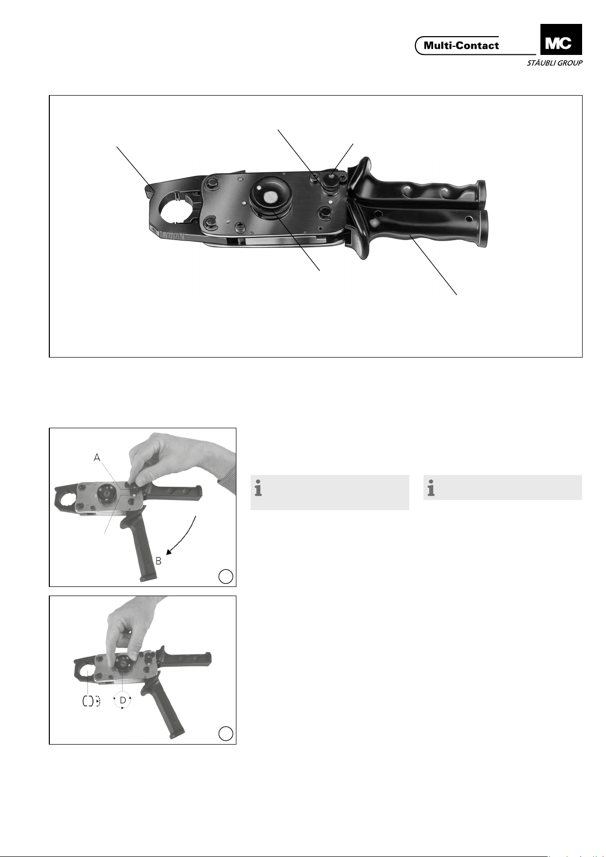
Perno de bloqueo
Palanca de cierre abatible
Latch
La herramienta de engarce es una prensa mecánica manual
con casquillos adaptables e intercambiables para engarzar:
• terminales de cables Cu y de conectores
• terminales tubulares de cables Cu y de conectores
• Casquillos de engarce Cu en conectores enchufables
C
Locking knob
A
Trinquete de retención
E
Holding catch
D
Mecanismo de avance rápido
Quick feed knob
The crimping tool is a mechanical hand press with interchangeable die inserts for crimping
• Copper cable lugs and connectors
• Tubular copper cable and connectors
• Crimp sleeves of connectors
B
Palanca manual móvil
Movable handle
Punto amarillo
Yellow point
(ill. 1)
Liberar la palanca móvil B girando el
perno de bloqueo A hasta alcanzar el
punto amarillo�
Nota:
durante esta operación, no
accionar la palanca manual.
1
(ill. 2)
Efectuar la aperturn total de la prensa
accionando el mecanismo de avance
rápido D�
(ill. 1)
Release the movable handle B by
turning the locking knob A to the yellow point �
Note:
Do not press together the handles.
(ill. 2)
Turn the quick feed knob D to move
press to bottom limit of movement�
2
www.multi-contact.com 3 / 8
Page 4

Advanced Contact Technology
Casquillos de engarce
Inserts
(ill. 3)
Abrir la palanca de cierre abatible C�
3
(ill. 4)
Alojar el casquillo de engarce adecuado a cada caso (consultar las instrucciones de engarce que se indican en
el manual de montaje)�
4
(ill. 5)
Cerrar la palanca abatible C, colocar
el terminal del cable o del conector
enchufable�
(ill. 3)
Open the latch C�
(ill. 4)
Insert the appropriate dies� (Also see
references to crimping in the
assembly instructions)�
(ill. 5)
Close latch C, insert cable connector,
cable lug or plug connector�
5
(ill. 6)
Observar la zona de engaste Z�
6
(ill. 7)
Accionando el mecanismo de avance
rápido D, levantar el punzón del cas-
quillo y jar el conector.
7
(ill. 6)
Observe the crimping zone Z�
(ill. 7)
Raise the die insert with the quick
feed knob D and x the connector in
place�
4 / 8 www.multi-contact.com
Page 5

Advanced Contact Technology
(ill. 8)
Colocar el cable
ce accionando la palanca manual� Dos
o tres carreras después de haberse
alcanzado el punto muerto superior se
puede echar hacia atrás la pieza guía
con ayuda del mecanismo de avance
rápido D y así poder retirar más rápidamente la pieza engarzada tal como
se describe en la Fig� 2�
8
1)
Consultar las instrucciones de engarce que se
indican en el manual de montaje�
(ill. 9)
Si se desea interrumpir el proceso de
engarce antes de haber alcanzado el
tope nal (con motivo de un posicionamiento erróneo o por equivocarse
de casquillo, por ejemplo), se deberá
proceder del modo siguiente: abatir
totalmente hacia fuera la palanca manual B y sujetarla� Apretar el trinquete
de retención E (soltarlo eventualmente
dando un ligero golpe con un martillo
de plástico)�La palanca de cierre abatible saltará y se abrirá y entonces se
9
puede echar hacia atrás el mecanismo
de avance rápido D�
Nota:
Si el proceso de engarce está
casi terminado, éste ya no se puede
interrumpir y en ese caso, hay que
terminar el proceso antes de poder
abrir los alicates de engarce.
1)
y proceder al engar-
(ill. 8)
Insert cable
actuating the movable handle B after
reaching the upper limit of movement,
by means of the quick feed knob D
the guide can be returned to its starting position as described under iIl� 2
to facilitate removal of the crimped
part�
1)
Also see references to crimping in the
assembly instructions�
(ill. 9)
Should the crimping operation have to
be stopped before completion (wrong
position, incorrect inserts etc�) proceed as following: Fully open handle
B and hold tight� Press down catch E
(if necessary, release by tapping gently
with a plastic hammer)� The latch
springs open� The quick feed knob D
can now be turned back�
Note:
When the crimping action is
almost nished it cannot be stopped.
The crimp must then be completed
before the tool can be opened.
1)
and effect crimping by
Comprobación del funcionamiento
de los alicates de engarce
Para cada uso en concreto, deberá
comprobarse que la presión de los
alicates y la profundidad del prensado
correspondiente estén de acuerdo
con la información que proporciona el
fabricante�
Material de prueba Test equipment
(ill. 10)
Casquillo de prueba, MPS-PZ13
Código 18�3707
10
Varilla redonda de aluminio blando,
MALU-PZ13
Código 18�3708 Inserto
(ill. 11)
Con los casquillos de prueba se com-
prime rmemente la varilla redondo
de aluminio blando (AL99,5) diámetro
16mm. La dimensión de 14,15mm.
no debe en ningún caso superar los
14�25� En el caso de una desviación
importante, enviar los alicates de
engarce al fabricante para un nuevo
reajuste�
Function test of the crimping
pliers
The crimping depth of crimping
pliers, adjusted by the manufacturer
should be tested from time to time�
(ill. 10)
Test insert, MPS-PZ13
Order No� 18�3707
Soft aluminium round rod,
MALU-PZ13
Order No� 18�3708
(ill. 11)
Press the soft-aluminium round rod
(AL99,5) Ø 16mm with the test
inserts. The size 14,15mm should not
exceed 14,25mm. With other test
results, the crimping pliers should be
adjusted by the manufacturer�
Nota:
Las reparaciones deben ser
11
www.multi-contact.com 5 / 8
solamente realizadas por personal
técnico especializado.
Note:
Repairs must only be performed
by qualied personnel.
Page 6

Advanced Contact Technology
Notas / Notes:
6 / 8 www.multi-contact.com
Page 7

Advanced Contact Technology
Notas / Notes:
www.multi-contact.com 7 / 8
Page 8

Advanced Contact Technology
Notas / Notes:
Fabricante/Producer:
Multi-Contact AG
Stockbrunnenrain 8
CH – 4123 Allschwil
Tel. +41/61/306 55 55
Fax +41/61/306 55 56
mail basel@multi-contact.com
www.multi-contact.com
© by Multi-Contact AG, Switzerland – MA224 – 10.2013, Index e, Global Communications – Sujeto a modicaciones / Subject to alterations
 Loading...