

Page 1
Advanced Contact Technology
MA223 (es_en)
Instrucciones de montaje
Conector hembra empotrable en panel o caja
PV-ADBP3/.../GWD
Conector macho empotrable en panel o caja PVADSP3/.../GWD
Conector hembra empotrable en panel o caja
con el cable MC-K.../PV-ADBP3/.../GWD
Conector macho empotrable en panel o caja con
el cable MC-K.../PV-ADSP3/.../GWD
Índice
Instrucciones de seguridad ........................................................2
Herramientas necesarias ...........................................................3
Cables de conexión ...................................................................3
Preparación del cable ...............................................................4
Conexiones por engarce ............................................................4
Engarce ....................................................................................4
—
con alicates de engarce PV-CZM-16100A .............................4
Montaje de los conectores empotrables ...................................5
Disposición del cable .................................................................6
Conexión ...................................................................................6
MA223 (es_en)
Assembly instructions
PV-Female panel receptacle PV-ADBP3/.../GWD
PV-Male panel receptacle PV-ADSP3/.../GWD
PV-Female panel receptacle with cable
MC-K.../PV-ADBP3/.../GWD
PV-Male panel receptacle with cable
MC-K.../PV-ADSP3/.../GWD
Content
Safety Instructions ......................................................................2
Tools required ............................................................................3
Connecting lead ........................................................................3
Cable preparation ......................................................................4
Crimp connections ....................................................................4
Crimping ....................................................................................4
—
with crimping pliers PV-CZM-16100A ....................................4
Assembly of panel receptacles ..................................................5
Cable routing .............................................................................6
Engagement ..............................................................................6
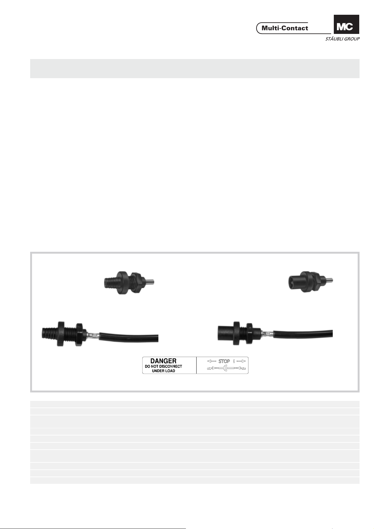
Conector hembra empotrable en panel o caja
Female panel receptacle
PV-ADBP3/.../GWD PV-ADBP3/.../GWD
con el cable / with cable con el cable / with cable
MC-K.../PV-ADBP3/.../GWD MC-K.../PV-ADSP3/.../GWD
Etiqueta adhesiva
Datos técnicos Technical data
Sistema de conectores Connector system Ø 3mm
Tensión nominal Rated voltage 1000V DC (IEC)
Corriente nominal Rated current
Tensión de control Test voltage 6kV (50Hz, 1min.)
Rango de temperatura ambiente Ambient temperature range -40°C...+85°C (IEC)
Temperatura límite superior Upper limiting temperature 105°C (IEC)
Tipo de protección, enchufado
desenchufado
Categoría de sobretensión / Grado de suciedad Overvoltage category / Pollution degree CATIII / 2
Resistencia de contacto de los conectores Contact resistance of plug connectors 0,5mΩ
Clase de protección Safety class II
Degree of protection, mated
Conector macho empotrable en panel o caja
Male panel receptacle
Sticker
20A (2,5mm
30A (6mm²)
unmated
IP65
IP2X
2
, 4mm²)
www.multi-contact.com 1 / 8
Page 2
Advanced Contact Technology
Instrucciones de seguridad Safety Instructions
Sólo personal adecuadamente cualifi cado y especialistas for-
mados podran realizar el montaje y la instalación de los productos teniendo en cuenta todas las regulaciones de seguridad aplicables.
Multi-Contact (MC) no se responsabiliza ante el incumplimiento de estas advertencias.
Utilice sólo los componentes y herrmientas indicadas por MC.
No se desvíe de los procedimientos de preparación y montaje
aquí descritos, en caso de una manipulación inadecuada no
se podrá garantizar la seguridad ni la conformidad con los datos técnicos. No modifi que el prodcuto en ningún caso.
Los conectores no fabricados por MC que se pueden conectar
con elementos MC, a veces denominados por los fabricantes
como „compatibles con MC“ no cumplen con los requisitos
para una conexión eléctrica segura y estable a largo plazo.
No pueden conectarse con elementos MC por motivos de seguridad. Por tanto, MC no se responsabilizará de los daños
surgidos por la conexión de conectores no autorizados por
MC con elementos MC.
Los trabajos aquí descritos no pueden ejecutarse
en piezas conectadas a la red y con tensión.
El producto fi nal debe proporcionar protección al
usuario frente a una descarga eléctrica.
Los conectores no pueden separarse estando cargados. Se permite la conexión y desconexión con
tensión.
Los conectores son impermeables según el tipo de
protección IP. Pero no están indicados para un largo
uso bajo agua. No coloque los conectores directamente sobre una cubierta.
Se deben proteger ante la humedad y suciedad los
conectores no conectados con una tapa de cierre
(MC3 nº de artículo 32.0720 para bornes y 32.0721
para enchufes). No se pueden conectar conectores
sucios.
El conector no debe someterse nunca a una tracción
mecánica duradera. El cable debe fi jarse con bridas.
Por razones de seguridad MC prohíbe el uso de ca-
bles de PVC o no estañados del tipo H07RN-F.
The products may be assembled and installed exclusively by
suitably qualifi ed and trained specialists duly observing all ap-
plicable safety regulations.
Multi-Contact (MC) does not accept any liability in the event of
failure to observe these warnings.
Use only the components and tools specifi ed by MC. In case
of self-assembly, do not deviate from the preparation and assembly instructions as stated herein, otherwise MC cannot
give any guarantee as to safety or conformity with the technical data. Do not modify the product in any way.
Connectors not originally manufactured by MC which can
be mated with MC elements and in some cases are even
described as ”MC-compatible” by certain manufacturers do
not conform to the requirements for safe electrical connection with long-term stability, and for safety reasons must not
be plugged together with MC elements. MC therefore does
not accept any liability for any damages resulting from mating
such connectors (i.e. lacking MC approval) with MC elements.
The work described here must not be carried out
on live or load-carrying parts.
Protection from electric shock must be assured by
the end product (i.e. by the correctly assembled
plug connector) and by its user.
The plug connections must not be disconnected
under load. Plugging and unplugging when live is
permitted.
The plug connectors are watertight in accordance
with the product specifi c IP protection class. How-
ever, they are not suitable for continuous operation under water. Do not place the plug connectors
directly on the roof membrane.
Unmated plug connectors must be protected from
moisture and dirt with a sealing cap (MC3 Article
No. 32.0720 sockets and 32.0721 for plugs). The
male and female parts must not be plugged together
when soiled.
The plug connection must not be subjected to
continuous mechanical tension. The cable should be
fi xed with cable binders.
For safety reasons MC prohibits the use of either
PVC cables or untinned cables of type H07RN-F.
Encontrará más detalles técnicos en el catálogo del
producto.
For further technical data please see the product
catalogue.
Explicación de los símbolos Explanation of the symbols
Advertencia de voltajes peligrosos
Advertencia de área de peligro Warning of a hazard area
Sugerencia o consejo útil Useful hint or tip
2 / 8 www.multi-contact.com
Warning of dangerous voltages
Page 3
Advanced Contact Technology
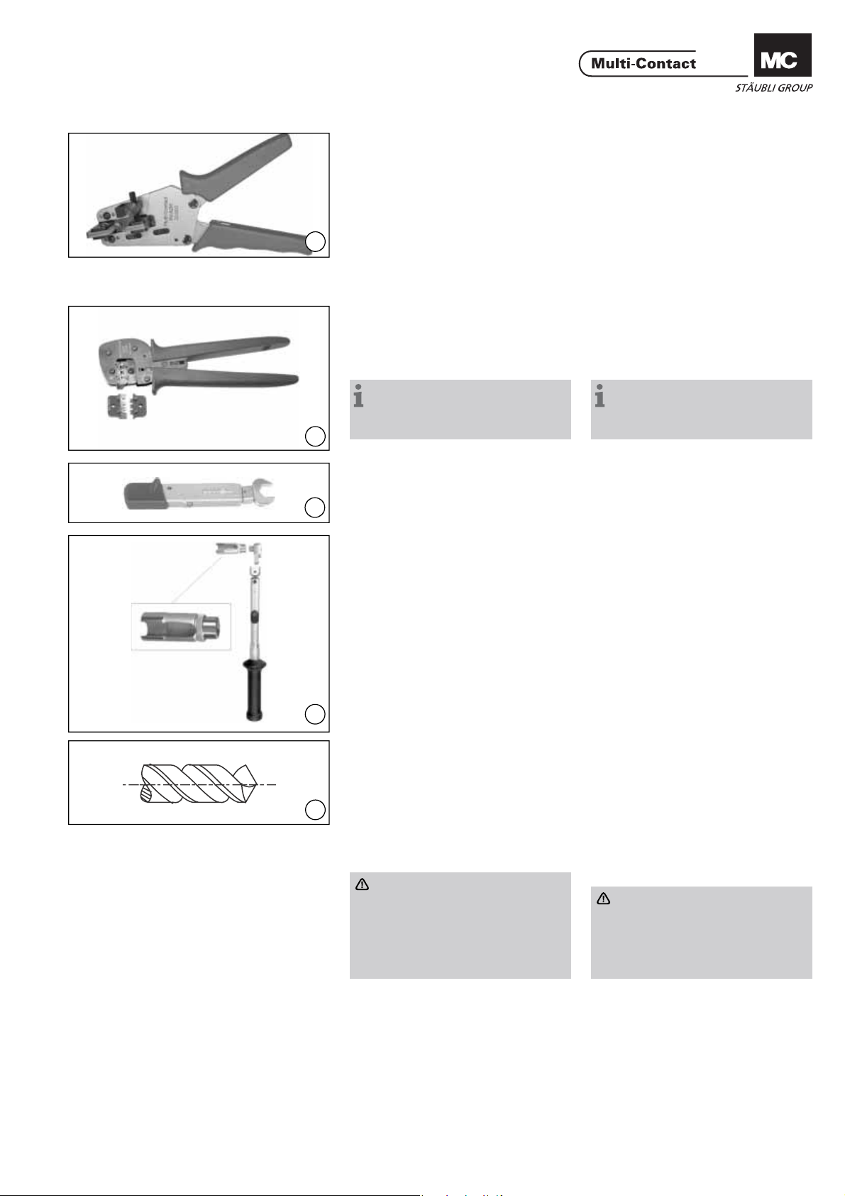
Herramientas necesarias Tools required
PV-CZM-16100A
(ill. 1)
Alicate pela-cables PV-AZM... y
destornillador hexagonal 2,5mm.
Sección del cable:
1,5 / 2,5 / 4 / 6mm²
Tipo: PV-AZM-1.5/6
1
No. de código 32.6029-156
(ill. 2)
Alicates de engarce PV-CZM-16100A
para una sección de cable de
2,5mm² – 10mm² / 14 / 12 / 10AWG
No. de código: 32.6020-16100A
Nota:
para la operación del alicate de
engarce consulte MA251
(www.multi-contact.com).
2
(ill. 3)
Llave dinamométrica de 17mm
3
o
(ill. 4)
Adaptador especial PV-WZ-AD/GWD
con hueco para calbes hasta Ø 10mm
para llave dinamométrica.
No. de código 32.6006
(ill. 1)
Stripping pliers PV-AZM... incl built-in
wire stripping blade as well as hexagonal screwdriver A/F 2,5mm.
Cable cross section: 1,5 / 2,5 / 4 / 6mm²
Type: PV-AZM-1.5/6
Order No. 32.6029-156
(ill. 2)
Crimping pliers PV-CZM-16100A for
cable cross section of
2,5mm² – 10mm² / 14 / 12 / 10AWG
Order No.: 32.6020-16100A
Notes:
to the operation of the crimping
pliers, see MA251
(www.multi-contact.com)
(ill. 3)
Torque spanner open-end with
A/F 17mm
or
(ill. 4)
Special socket wrench
PV-WZ-AD/GWD with recess for
cables up to max. Ø 10mm.
Order No. 32.6006
4
(ill. 5)
Broca Ø 12,5mm
(ill. 5)
Drill Ø 12,5mm
Cables de conexión Connecting lead
5
Pueden conectarse cables de clase 5
o 6 (de acuerdo con IEC 60228, DIN
VDE 0295) con secciones de cable de
2
2,5mm
Comprobar el diámetro del hilo de cobre. Pueden ser utilizados condutores
multifi lares en medidas AWG.
– 6mm2.
Atención:
No utilice cables oxidados o sin
revestimiento. Es aconsejable
utilizar conductores estañados.
Los cables solares MC cuentan
con conductores estañados de
alta calidad.
Cables with a strand construction
of classes 5 and 6 (according to IEC
60228, DIN VDE 0295) with cable
cross section of 2,5mm
be connected.
Attention:
Use no uncoated or already oxidised conductors. It is advantage
to use tinned conductors. All MC
solar cables have high-quality,
tinned conductors.
Check strand diameter.
Multi-stranded conductors in AWG
gauges can be used.
2
– 6mm2 can
www.multi-contact.com 3 / 8
Page 4

Advanced Contact Technology
L
Tab. 1
Tipo
Type
PV-BP3/4 6 – 7,5
PV-SP3/4 6 – 7,5
PV-BP3/6 8,5 – 9,5
PV-SP3/6 8,5 – 9,5
2,5mm
Longitud L (mm)
Length L (mm)
4mm
2
Preparación del cable Cable preparation
(ill. 6 / Tab. 1)
Pelar el cable.
Longitud de acuerdo con la Tab. 1
6
2
Atención:
Tenga cuidado de no cortar ningún hilo.
Nota:
para obtener instrucciones sobre
cómo utilizar los alicates pela cables
PV-AZM... y cómo cambiar las hojas
de corte, consulte MA267
www.multi-contact.com
(ill. 6 / Tab. 1)
Strip cable insulation.
Length according Tab. 1
Attention:
Take care not to cut individual
strands.
Note:
for directions on the operation of
stripping pliers PV-AZM... and changing blade sets, see operating instruction MA267 at www.multi-contact.com
Conexiones para engarzar Crimp connections
2
6mm
Para conectar los conductores a los
casquillos de engarce de los conectors PV, recomendamos utilizar las
herramientas de engarce indicadas en
esta hoja de instrucciones.
For the connection of the conductors
to the crimping sleeves of the PV plug
connectors, we recommend using the
stated crimping tools.
Engarce Crimping
con alicates de engarce
PV-CZM-16100A
with crimping pliers
PV-CZM-16100A
Q
Quitar el localizador. Remove the locator.
(ill. 7)
Coloque la parte metálica del pin
macho o hembra en la guía para la
sección de cable correspondiente.
Inserte el cable de la izquierda.
7
(ill. 8)
Atención:
Todos los conductores deben ser
introducidos deben ser introducidos en el orifi cio Q dejando
una distancia máxima visible de
1mm.
8
Cierre completamente la herramienta
de engarce.
Nota:
para el cambio del posicionador y
las correspondientes matrices, por
favor, diríjase al manual MA251,
www.multi-contact.com
(ill. 9)
9
Verifi que la crimpadora en forma
visual.
(ill. 7)
Place the metal part of the female
or male coupler in the guide for the
appropriate cross section. Insert the
cable from the left.
(ill. 8)
Attention:
All strands of the wires must be
correctly inserted into the bore
hole and visible in sight hole Q.
The max. distance of 1mm must
not be exceeded.
Completely close the crimping tool.
Note:
for the replacement of the locator and the corresponding crimping
inserts, please see MA251 at
www.multi-contact.com
(ill. 9)
Visually check the crimp.
4 / 8 www.multi-contact.com
Page 5

Advanced Contact Technology
max. 5 mm
Montaje de los conectores
empotrables
(ill. 10)
Taladrar la pared del panel
(Ø 12,5mm).
Assembly of panel receptacles
(ill. 10)
Drill a hole (Ø 12,5mm) in the wall of
the housing (max. 5mm wall thickness).
+0.2
- 0, 4
Ø12,5
10
(ill. 11)
Introducir los conectores empotrables
junto con el cable engarzado en el
(ill. 11)
Feed crimped cable with panel receptacles through the drill hole.
taladro practicado.
11
(ill. 12)
Colocar a mano la tuerca hexagonal.
Atención:
Es muy importante fi jar los co-
nectores empotrables con ayuda
de las tuercas de plástico que
acompañan al suministro (las dos
piezas se complementan una con
otra).
12
(ill. 13)
Apretar la tuerca con la lave dinamométrica. Par de apriete 2Nm.
13
(ill. 14)
Enganche el adhesivo „DANGER – DO
NOT DISCONNECT UNDER LOAD“
en la carcasa de la aplicación lo más
14
cerca posible de los paneles fotovoltaicos.
(ill. 12)
Screw on the hex. nut by hand.
Attention:
It is important that the panel
receptacles are fi xed with the de-
livered plastic nuts. (Parts match
each other).
(ill. 13)
Tighten nut with the torque spanner
(tightening torque 2Nm).
(ill. 14)
Attach enclosed sticker „DANGER
- DO NOT DISCONNECT UNDER
LOAD“ to the applicance housing as
near as possible to the PV panel male
receptacle.
www.multi-contact.com 5 / 8
Page 6

Advanced Contact Technology
Disposición del cable Cable routing
Referir a la especifi cación del fabrican-
te del cable para el radio de curvatura.
Refer to calbe manufactures specifi ca-
tion for minimum bending radius.
Conexión Engagement
Verifi que que las piezas de conexión
se encuentren totalmente aseguradas.
Check that the coupler parts are fully
engaged.
6 / 8 www.multi-contact.com
Page 7

Advanced Contact Technology
Notas / Notes:
www.multi-contact.com 7 / 8
Page 8

Advanced Contact Technology
Notas / Notes:
Fabricante/Producer:
Multi-Contact AG
Stockbrunnenrain 8
CH – 4123 Allschwil
Tel. +41/61/306 55 55
Fax +41/61/306 55 56
mail basel@multi-contact.com
www.multi-contact.com
© by Multi-Contact AG, Switzerland – MA223 – 02.2012, Index i, Global Communications – Sujeto a modifi caciones / Subject to alterations
 Loading...