

Page 1
Advanced Contact Technology
MA221 (de_en_fr)
Montageanleitung
Stift- und Buchsengehäuse
FL3-24+PE/...PA FL3-36+PE/...PA
für Werkzeugwechselsysteme
Bei der Benutzung von anderen als von
MC angegebenen Einzelteilen und Werkzeugen, sowie bei Abweichung der hier
beschriebenen Vorgänge zur Vorbereitung und
Montage, kann bei der Selbstkonfektionierung
weder die Sicherheit, noch die Einhaltung der
technischen Daten gewährleistet werden.
Zum Schutz vor einem elektrischen
Schlag müssen die Bauteile bei der Montage
oder Demontage immer allseitig von der
Stromversorgung getrennt sein.
Das Stecken und Trennen von Steckverbindungen hat generell in stromlosem Zustand
zu erfolgen.
FL3-BG-24+PE/...PA
FL3-BG-36+PE/...PA
MA221 (de_en_fr)
Assembly instructions
Pin and socket housing
FL3-24+PE/...PA FL3-36+PE/...PA
for tool-changing systems
f, during self assembly, parts and tools
I
other thanthosestated by MC areusedor if the
preparation and assembly instructions
described here aredisregardedthen neither the
safety nor compliance with the technical data
can be guaranteed.
For protection against electric shock,
parts must be isolated from the power supply
while being assembledordisassembled.
Connectors may not be connected or
disconnected under load.
MA221 (de_en_fr)
Instructions de montage
Boîtier mâle et femelle
FL3-24+PE/...PA FL3-36+PE/...PA
pour systèmes de changement
d'outil
Lors de l’assemblage, si des composants
et des outils différents de ceux prescrits par MC
étaient utilisés, si en outre les instructions de
montage ci-après n’étaient pas strictement
appliquées, ni la sécurité, ni la conformité aux
caractéristiques techniques ne sauraient être
garanties.
En vue de garantir une protection contre
les chocs électriques, il est indispensable de
réaliser les opérations de montage et de
démontage hors tension, en veillant à
déconnecter les différents composants de
toute alimentation électrique.
En règle générale, il ne faut pas embrocher ou débrocherunconnecteursouscharge.
FL3-SG-24+PE/...PA
FL3-SG-36+PE/...PA
Für Plattenabstand 12,5 ,
Plattendicke 10
-0,1
0
+1
0
For plate spacing 12,5 ,
Plate thickness 10
Kleine Nut / small groove / petite rainure
-0,1
+1
0
0
Pour distance entre plaques 12,5 ,
Epaisseur de plaque 10
-0,1
0
2
4
1
9,10
6,7
5
3
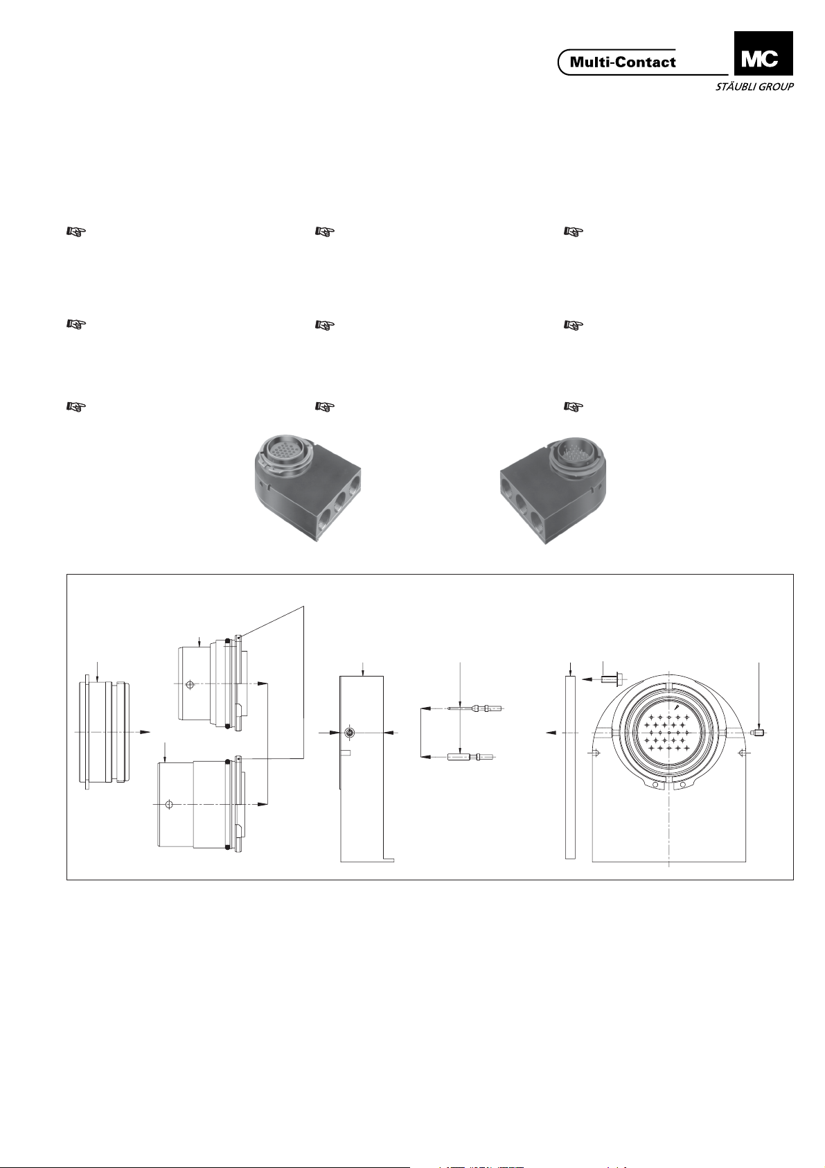
Anlieferzustand: komplett montiert Supplied fully assembled Livré entièrement monté
1
= Stift-bzw. Buchsengehäuse Unterteil
2
= Stiftgehäuse Vorderteil
3
= Buchsengehäuse Vorderteil
4
= Haltering
5
= Gehäusedeckel
6
= Federscheibe
7
= Zylinderschraube
8
= Gewindestift
bzw. Teil 3 in Teil 1, rechts oder links
einschraubbar)
9
= Stift
10
= Buchse
(Zur Sicherung von Teil 2
1
= Pin or socket housing bottom part
2
= Pin housing front part
3
= Socket housing front part
4
= Securing ring
5
= Cover
6
= Lock washer
7
= Screw
8
= Socket set screw (to fix part 2 or
part 3 in part 1, to screw in on the
left or the right side)
9
= Pin
10
= Socket
1
= Boîtier arrière mâle ou femelle
2
= Boîtier avant mâle
3
= Boîtier avant femelle
4
= Bague de fixation
5
= Couvercle
6
= Rondelle éventail
7
=Vis
8
= Embout fileté (pour fixer la partie 2 ou
3 à la partie 1, peut être vissé du côté
droit ou gauche)
9
= Broche
10
= Douille
+1
0
8
www.multi-contact.com
1/8
Page 2
Advanced Contact Technology
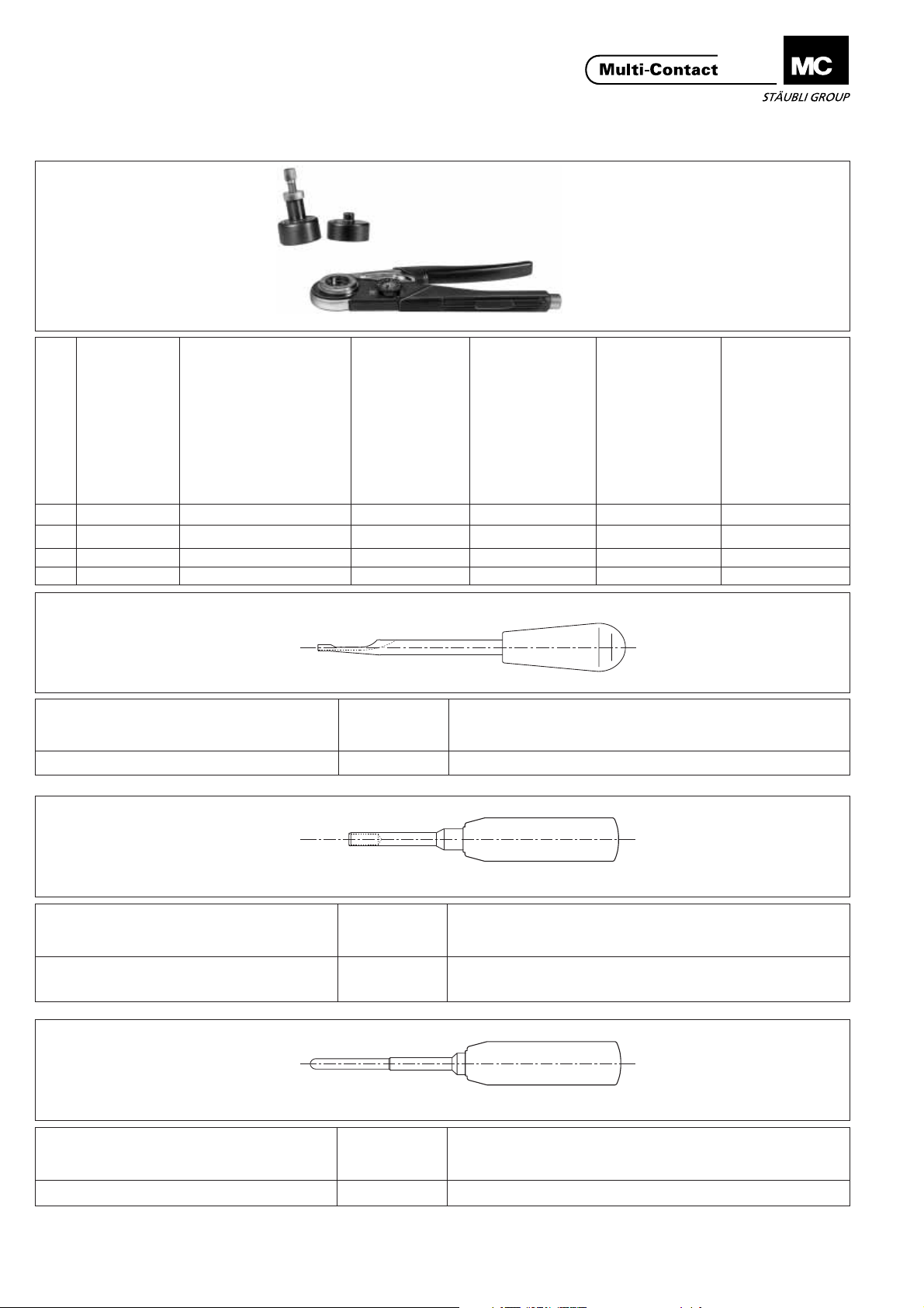
Notwendiges Werkzeug Tools required Outillage nécessaire
2
1
Position (ill.2)
1 M-CZ 18.3800
2 MES-CZ 18.3801 1-3 0,14-4 1+2
3 MES-CZ1,5/2 18.3802 1,5/2 0,5-1,5 1+3
verstellbar
adjustable
réglable
nicht verstellbar
not adjustable
non réglable
3
ill.2
Bestell-Nr.
Order No.
No. de Cde
Nenn-Ø Stift/Buchse
Nom.-Ø pin/socket
Ø-nom. broche/douille
mm
Leiterquerschnitt
Conductor cross-section
Section du câble
mm²
Bestellung
Order
Commande
ill.3
Einsetzwerkzeug Stift/Buchse Bestell-Nr. Für Nenn-Ø Stift/Buchse
Insertion tool pin/socket Order No. For nom.-Ø Pin/socket
Outil de montage broche/douille No. de Cde Pour Ø-nom. broche/douille
ME-WZ1,5/2 18.3003 1,5 / 1,57 / 2 / 2,36
Stiftausbauwerkzeug Bestell-Nr. Für Nenn-Ø Stift/Buchse
Extraction tool (pin) Order No. For nom.-Ø Pin/socket
Outil de démontage (broche) No. de Cde Pour Ø-nom. broche/douille
MSA-WZ1,5 18.3005 1,5 / 1,57
MSA-WZ2 18.3009 2
ill.3
ill.4
ill.4
ill.5
Buchsenausbauwerkzeug Bestell-Nr. Für Nenn-Ø Stift/Buchse
Extraction tool (socket) Order No. For nom.-Ø Pin/socket
Outil de démontage (douille) No. de Cde Pour Ø-nom. broche/douille
MBA-WZ1,5 18.3004 1,5 / 1,57
2/8
ill.5
www.multi-contact.com
Page 3
Advanced Contact Technology
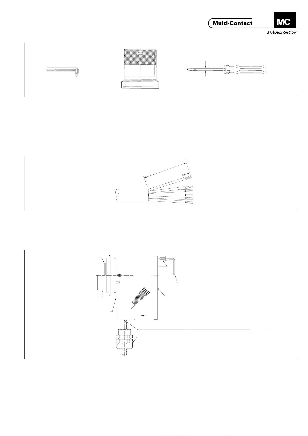
max. Ø4mm
ill.6
(ill.6)
Sechskant-Schraubendreher SW2 &
SW2,5
Montagering FL3-M-RG
Bestell-Nr. 18.0948
und 1 Schraubendreher (oder ähnlich)
als Drehhebel für den Montagering.
Vorbereiten der Leitung
(ill.7)
Kabel und Einzelleiter auf angegebenes
Mass abisolieren (Richtwert).
Zusammenbau
(ill.6)
Hex. key wrench A/F2 & A/F2,5
Assembly ring FL3-M-RG
Order No. 18.0948
and a screw driver (or similar) to turn the
assembly ring.
(ill.6)
Clé à 6 pans 2mm et 2,5mm
Bague de montage FL3-M-RG
No. de Cde 18.0948
et un tournevis (ou similaire) pour
tourner le bague de montage.
Preparation of cable Préparation du câble
100
7
ill.7
(ill.7)
Strip indicated length from cable and
lead insulation.
(ill.7)
Dégainer le câble et les conducteurs sur
la longueur indiquée.
Assembly Assemblage
2
3
(ill.8)
Zylinderschrauben (7) von Gehäusedeckel (5) mittels SechskantSchraubendreher SW2,5 lösen,
Gehäusedeckel (5) abnehmen.
Achtung:
Gehäuseunterteil (1) und im
Bedarfsfall Kabelverschraubung, vor
Vercrimpen, auf Leitung auffädeln.
6,7
Sechskant-Schraubendreher SW2,5
Hex. Key wrench A/F2,5
Clé à 6 pans 2,5mm
5
1
Gewinde-Öffnungen/Threaded openings/Ouvertures filetées
Kabelverschraubung/Cable gland/Presse-étoupe
ill.8
(ill. 8)
Unscrew screws (7) from the cover (5)
with a hex key wrench A/F 2.5, remove
cover from housing.
Important:
Before crimping, pass the cable
through the lower part of the housing
(1) and, if necessary, the cable gland.
(ill.8)
Desserrer les vis (7) du couvercle de
boîtier (5) au moyen de la clé à 6 pans
2,5 mm, enlever le couvercle de boîtier
(5).
Attention:
Enfiler le boîtier arrière (1) et si
nécessaire le presse-étoupe sur le
câble avant de sertir.
www.multi-contact.com
3/8
Page 4

Advanced Contact Technology
Crimpen der Kontakte Crimping the contacts Sertissage des contacts
Sichtloch
Control hole
Orifice de contrôle
ill.9
(ill.9)
Einzelleiter in die Crimphülse des Kontaktes bis zum Anschlag einführen bis
sie im Sichtloch der Kontakte erscheinen.
Crimpvorgang ausführen. Leiter dabei
leicht in axialer Richtung in Crimphülse
drücken.
(ill.10)
Angeschlossene Leiter müssen nach
dem Crimpen im Sichtloch sichtbar sein.
Leiter darf sich nicht aus der Crimphülse
herausziehen oder abreissen lassen.
(Kontrolle !).
Einbau der Kontakte
ill.10
(ill.9)
Fully insert conductor into the crimping
sleeve until the conductor is visible in
the control hole.
Crimp the conductor, pushing it gently
into the sleeve while doing so.
(ill.9)
Introduire le conducteur dans le fût à sertir jusqu’à ce qu’il apparaisse dans
l’orifice de contrôle.
Sertir, tout en maintenant le conducteur
en position dans le fût (pousser axialement).
(ill.10)
The conductor must be visible in the control hole after crimping. Check that the
conductor cannot be pulled or twisted
out of the crimping sleeve.
(ill.10)
Le conducteur doit être visible dans l'orifice de contrôle après sertissage. Vérifier la qualité de sertissage en exerçant
une traction sur le conducteur.
Assembly of the contacts Assemblage du connecteur
Industriealkohol
Industrial alcohol
Alcool industriel
(ill.11)
Hinweis:
Der Einpressvorgang kann erleichtert
werden, wenn die Stift bzw. Buchsenträger vor dem Einsetzen der Kontakte
in Spiritus oder Industriealkohol getaucht werden. Keine fetthaltigen Medien (kein Talkum) benutzen. Bei Teilbestückung der Kontaktträger mit Stiften
bzw. Buchsen müssen, zur Sicherstellung der Längswasserdichtheit, die nicht
bestückten Kontaktkammern mit Verschlussstopfen MVS-1,5/2 Bestell-Nr.
18.5500 verschlossen werden.
4/8
ill.11
(ill.11)
Installation tips:
To facilitate installation, immerse the pin
or socket carrier in spirits or industrial alcohol before inserting the contacts. Do
not use any greasy media (no talc).To
prevent water penetration, any unoccupied contact holes must be plugged
with blind plugs MVS-1,5/2, order no.
18.5500.
www.multi-contact.com
(ill.11)
Remarques:
Le montage des broches et des douilles
peut être facilité en plongeant les supports dans du "White spirit" ou de l'alcool industriel, mais ne pas utiliser de
substances grasses (pas de talc).
Mettre des bouchons d'obturation MVS1,5/2, No. de Cde 18.5500 dans les logements non utilisés.
Page 5

Advanced Contact Technology
Kontakte in die Kontaktkammern der
Stift- bzw. Buchsenträger von der Anschlussseite her (grösserer Ø der Kontaktkammern) mit normaler Handkraft
vorstecken. Kontakte mit Kontakteinsetzwerkzeug eindrücken.
Beim Stifteinbau wird als Montagehilfe
ein Stiftgehäuse-Vorderteil empfohlen.
Beim Buchseneinbau wird der Buchsenträger direkt auf eine ebene Unterlage
gestellt.
Werkzeug beim Eindrücken und Herausziehen parallel zur Achse führen.
Überprüfung auf einwandfreie
Konfektionierung
Beim Stifteinsatz müssen alle Stifte
steckseitig gleich weit aus dem Stiftträger stehen, mit Ausnahme des PEStiftes, bei Kontakten bis Ø 2mm, voreilend ca. 2mm.
Beim Buchsenträger liegen die Buchsen
(bis Ø 2mm) in einer Ebene hinter dem
verjüngten Einlauf. Bei Buchsen ab Ø
3mm eilt die PE-Buchse vor.
Insert contacts by hand into the contact
holes of the pin or socket carrier from
the connection side (larger hole Ø).
Press in the contacts with the insertion
tool.
For the insertion of the pins, it is advisable to use the front part of an appropriately sized housing as an assembly jig. To
install sockets, simply place socket carrier directly on a flat bench.
Be sure to keep tool straight when installing or removing contacts.
Emmancher à la main les contacts dans
leur logement respectif, par la face arrière du corps isolant (grand Ø des logements).
Terminer le montage des contacts à l'aide de l'outil approprié.
Pour le montage des broches, poser le
support isolant sur le boîtier avant correspondant. Pour le montage des douilles,
poser le support isolant sur une surface
plane.
Lors du montage ou du démontage des
contacts, veiller à manipuler les outils
parallèlement à l'axe du support.
Control of correct assembly Contrôle du montage
In pin carriers, all pins should project the
same distance out of the carrier. Exception: The PE-pin on contacts up to Ø
2mm should project about 2mm further.
In socket carriers, the sockets (up to Ø
2mm) are all seated in the same plane
behind the tapered opening. The PE socket is advanced in the case of sockets
on Ø 3mm or larger.
Après leur mise en place, vérifier que
toutes les broches sont au même niveau par rapport au support isolant. Exception: les broches de terre pour contacts de Ø 2mm max. doivent être 2mm
plus en avant par rapport aux autres broches. Toutes les douilles jusqu'au
Ø 2mm doivent être au même niveau
dans le support. A partir de Ø 3mm, la
douille de terre sera en avant par rapport
aux autres douilles du support.
(ill12)
Zu weit eingedrückte Buchsen werden
mit dem Buchsenausbauwerkzeug (ill.5)
bis zu ihrer Einrastlage zurückgedrückt.
Bei Belegungsfehlern und Reparaturen
werden die Kontakte mit den entsprechenden Ausbauwerkzeugen (ill.4, ill.5)
aus den Kontaktträgern gedrückt und
neu eingesetzt.
ill.12
(ill12)
Sockets pressed in too far can be
pushed back to their correct seating position with the socket extraction tool
(ill. 5).
In case of repairs or installation errors,
remove the contacts from the contact
carrier with the appropriate extraction
tool (ill.4, ill.5) and then reinstall them
correctly.
www.multi-contact.com
(ill12)
Les douilles trop enfoncées peuvent
être ramenées dans leur position nominale à l'aide de l'outil de démontage de
douille (ill.5).
En cas d'erreurs de montage ou lors
d'une réparation, extraire les contacts
du support isolant avec l'outil de démontage approprié (ill.4, ill.5) puis les réinsérer correctement.
5/8
Page 6

Advanced Contact Technology
(ill.13)
Achtung:
Kabelverschraubung erst nach der
Montage der Kontakte und nach dem
Ausrichten der Einzelleiter im Gehäuse
festschrauben.
Deckel (4) schliessen und mittels
Federscheiben und Schrauben (5, 6)
befestigen.
5,6
4
ill.13
(ill13)
Attention:
Do not screw-on the Pg-threaded gland
before the contacts are assembled and
the leads are lined up.
Fit cover (4) and screw down with lock
washers and screws (5, 6).
(ill13)
Attention:
Avant de serrer le presse-étoupe (Pg)
veiller à monter correctement le pièces
de contact et à aligner les conducteurs.
Fermer le couvercle (4) et fixer le avec
les rondelles éventails et les vis (5,6).
Demontage Disassembly Démontage
2,3
ill.14
(ill14)
Die Demontage erfolgt in umgekehrter
Reihenfolge. Im Reparaturfall können
die Einzelkontakte bzw. die GehäuseVorderteile ausgetauscht werden.
Gehäusedeckel (5) mittels SechskantSchraubendreher SW2,5 lösen. Deckel
abnehmen.
(ill. 14)
Disassembly is carried out in the
reverse order.
In the event of damage the individual
contacts and front parts of the housings
can be replaced. Remove cover (5) by
means of hex key wrench A/F2.5.
(ill.14)
Le démontage s'effectue dans l'ordre
inverse du montage. En cas de
réparation, les contacts ou les boîtiers
avant peuvent être remplacés.
Desserrer le couvercle de boîtier (5) au
moyen de la clé à 6 pans 2,5 mm.
Enlever le couvercle.
6/8
www.multi-contact.com
Page 7

Advanced Contact Technology
Kleine Nut / small groove / petite rainure
1
9
9
7
5
6
(ill.15).
Die Kontakte werden von der
Steckseite her mittels Stiftausbauwerkzeug (ill.4) bzw. Buchsenausbauwerkzeug (ill.5) herausgedrückt.
Gewindestift (8) mit dem SechskantSchraubendreher SW2 (7) herausschrauben.
Das Stiftgehäuse- (1) bzw. Buchsengehäuse-Vorderteil (2) mittels Montagering (5) und dem Schraubendreher
(6) als Drehebel aufschrauben. Danach
das Stiftgehäuse- (1) bzw. Buchsengehäuse-Vorderteil (2) von Hand in
axialer Richtung abziehen. Das neue
Stiftgehäuse- (1) bzw. Buchsengehäuse-Vorderteil (2) lagerichtig (Nut
passend zu Führungsstift) einbauen
(von Hand eindrücken. Es ist unbedingt darauf zu achten, dass das Stift(1) bzw. Buchsengehäuse-Vorderteil (2)
in das richtige, entsprechende
Gehäuse-Unterteil (10, siehe Aufschrift)
eingesetzt wird. Haltering (9) mittels
Montagering (5) wieder aufschrauben,
danach den Gewindestift (8) zur
Fixierung des Haltering's (9) mittels
Sechskant-Schraubendreher SW2 (7)
wieder einschrauben.
2
10
ill.15
(ill. 15)
Press out the contacts from the
connection side with the pin extraction
tool (ill.4) or socket extraction tool (ill.
5). Remove the setscrew (8) with hex
key wrench A/F2 (7).
Unscrew front part of pin housing (1)
or socket housing (2) with the
assembly ring (5), turning with the
screwdriver (6) as a lever. Then, by
hand, pull off the pin (1) or socket (2)
housing front part in an axial direction.
Fit the new pin (1) or socket (2)
housing front part in the correct
position (slot in line with guide pin),
pressing in by hand. Check carefully
that the pin or socket housing front
part is fitted into the correct housing
lower part (10, see marking). Screw
the securing ring (9) back in place with
the assembly ring (5), then screw in
the setscrew (8) to fix the securing
ring (9) using a hex key wrench A/F 2
(7)
8
(ill.15)
Les contacts peuvent être extraits par la
face d'embrochage à l'aide de l'outil de
démontage adapté (ill.4 ou ill.5).
Dévisser l'embout fileté (8) à l'aide de la
clé à 6 pans 2 mm.
Dévisser le boîtier avant mâle (1) ou
femelle (2) à l'aide de la bague de
montage (5) et le tournevis (6) utilisé
comme levier). Tirer ensuite le boîtier
avant mâle (1) ou femelle (2) en
direction axiale à la main. Remonter le
nouveau boîtier avant mâle (1) ou
femelle (2) dans la position correcte
(rainure correspondant à la goupille de
guidage) (enfoncer à la main). Veiller
impérativement à mettre en place le
boîtier avant mâle (1) ou femelle (2) dans
le boîtier arrière qui lui correspond (10,
voir marquage). Revisser la bague de
fixation (9) au moyen de la bague de
montage (5), puis revisser l'embout
fileté (8) au moyen de la clé à 6 pans 2
mm (7) pour fixer la bague de fixation
(9).
www.multi-contact.com
7/8
Page 8

Advanced Contact Technology
Beispiel
Bohrplan
-0,5
+0,5
91
Example
Drilling plan
0
+0,1
62
12,5
Ø3H7
Exemple
Plan de perçage
±0,1
II
Zylinderstift ø 3
Setscrew ø 3
Goupille de position ø 3
II
Es müssen 2 Zentrierstifte
eingesetzt werden. Zulässiger
Winkelversatz Stift- Buchsenseite
± 0,5°
Zulässige x-y Abweichung von Stiftund Buchsenseite ± 0,2 mm
Two centring pins are to be used.
Permissible angular deviation of the
pin and of the socket sides
± 0,5°
Permissible x-y deviation of the pin
and the socket sides ± 0,2 mm.
2 goupilles de position doivent être
installées. Déplacement angulaire
admissible entre la fiche et la douille
± 0,5°
Déviation x-y admissible du côté
fiche et du côté douille ± 0,2 mm.
MA221 (de_en_fr)
8/8
Änderungen vorbehalten / Subject to alterations / Modifications sous réserve
Copyright by Multi-Contact AG, Switzerland / / 11.2006 / Index bDocking
www.multi-contact.com
line
 Loading...