

Page 1

Advanced Contact Technology
MA000 (de_en)
MA213-02 (es_en)
Montageanleitung
Instrucciones de montaje
MA000 (de_en)
MA213-02 (es_en)
Assembly instructions
Assembly instructions
Conectores coaxiales para MC CombiTac Coaxial connectors for MC CombiTac
Índice
Instrucciones de seguridad ........................................................2
Herramientas necesarias ........................................................... 3
Perparación de los cables ..........................................................3
Montaje de los cables ................................................................3
Verifi cación del montaje ............................................................5
Desmontaje de los contactos ....................................................5
Notas .........................................................................................6
Content
Safety Instructions ....................................................................2
Tools required ............................................................................3
Cable preparation ......................................................................3
Cable assembly .........................................................................3
Checking of assembly ...............................................................5
Extraction of contacts ................................................................5
Notes .........................................................................................6
www.multi-contact.com 1 / 8
Page 2
Advanced Contact Technology
Instrucciones de seguridad Safety instructions
Sólo personal adecuadamente cualifi cado y especialistas for-
mados podran realizar el montaje y la instalación de los productos teniendo en cuenta todas las regulaciones de seguridad aplicables.
Multi-Contact (MC) no se responsabiliza ante el incumplimiento de estas advertencias.
Utilice sólo los componentes y herrmientas indicadas por MC.
No se desvíe de los procedimientos de preparación y montaje
aquí descritos, en caso de una manipulación inadecuada no
se podrá garantizar la seguridad ni la conformidad con los datos técnicos. No modifi que el prodcuto en ningún caso.
Los conectores no fabricados por MC que se pueden conectar
con elementos MC, a veces denominados por los fabricantes
como „compatibles con MC“ no cumplen con los requisitos
para una conexión eléctrica segura y estable a largo plazo.
No pueden conectarse con elementos MC por motivos de seguridad. Por tanto, MC no se responsabilizará de los daños
surgidos por la conexión de conectores no autorizados por
MC con elementos MC.
Los trabajos aquí descritos no pueden ejecutarse
en piezas conectadas a la red y con tensión.
El producto fi nal debe proporcionar protección al
usuario frente a una descarga eléctrica.
Los conectores no pueden separarse estando cargados. Se permite la conexión y desconexión con
tensión.
Cada vez que el conector sea usado, éste debe ser
inspeccionado previamente por posibles defectos
externos (particularmente en el aislante). Si hay
alguna duda para su seguridad, se debe consultar a
un especialista o el conector debe ser reemplazado.
Los conectores en carcasa están protegidos contra
el agua conforme a la clase de protección IP informada para el producto respectivo.
Se deben proteger ante la humedad y suciedad los
conectores no conectados. No se pueden conectar
conectores sucios.
The products may be assembled and installed exclusively by
suitably qualifi ed and trained specialists duly observing all ap-
plicable safety regulations.
Multi-Contact (MC) does not accept any liability in the event of
failure to observe these warnings.
Use only the components and tools specifi ed by MC. In case
of self-assembly, do not deviate from the preparation and assembly instructions as stated herein, otherwise MC cannot
give any guarantee as to safety or conformity with the technical data. Do not modify the product in any way.
Connectors not originally manufactured by MC which can
be mated with MC elements and in some cases are even
described as ”MC-compatible” by certain manufacturers do
not conform to the requirements for safe electrical connection with long-term stability, and for safety reasons must not
be plugged together with MC elements. MC therefore does
not accept any liability for any damages resulting from mating
such connectors (i.e. lacking MC approval) with MC elements.
The work described here must not be carried out
on live or load-carrying parts.
Protection from electric shock must be assured by
the end product (i.e. by the correctly assembled
plug connector) and by its user.
The plug connections must not be disconnected
under load. Plugging and unplugging when live is
permitted.
Each time the connector is used, it should previously
be inspected for external defects (particularly in the
insulation). If there are any doubts as to its safety, a
specialist must be consulted or the connector must
be replaced.
The plug connectors in the housing are protected
from water in accordance with the IP protection
class stated for the relevant product.
Unmated plug connectors must be protected from
moisture and dirt. The male and female parts must
not be plugged together when soiled.
Encontrará más detalles técnicos en el catálogo del
producto.
For further technical data please see the product
catalogue.
Explicación de los símbolos Explanation of the symbols
Advertencia de voltajes peligrosos
Advertencia de área de peligro Warning of a hazard area
Sugerencia o consejo útil Useful hint or tip
2 / 8 www.multi-contact.com
Warning of dangerous voltages
Page 3
Advanced Contact Technology
Herramientas necesarias Tools required
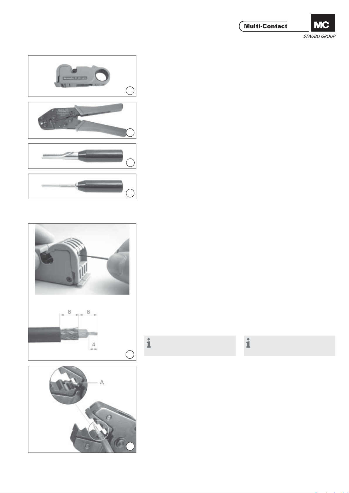
(ill. 1)
Alicates pelacables CT-AIWZ/COAX
N° de código: 33.3011
1
(ill. 1)
Insulation stripper CT-AIWZ/COAX
Order No. 33.3011
(ill. 2)
Alicates de engarce CT-CZ/COAX
N° de código: 33.3010
2
(ill. 3)
Herramientas de montaje para machos y hembras ME-WZ5
3
N° de código: 18.3013
(ill. 4)
Herramienta de extracción para hembras MSAWZ5
4
N° de código: 18.3015
Herramienta de extracción para machos MSAWZ8
N° de código: 18.3022
(ill. 2)
Crimping pliers CT-CZ/COAX
Order No. 33.3010
(ill. 3)
Insertion tool pin / socket ME-WZ5
Order No. 18.3013
(ill. 4)
Extraction tool (socket) MSA-WZ5
Order No. 18.3015
Extraction tool (pin) MSA-WZ8
Order No. 18.3022
Perparación de los cables Cable preparation
(ill. 5)
Ajustar el útil pela-cables
CT-AIWZ/COAX a la cota deseada y
proceder a pelar el cable.
(ill. 5)
Adjust the insulation stripper
CT-AIWZ/COAX according to the indicated dimensions and strip the cable.
Montaje de los cables Cable assembly
Nota:
el procedimiento de montaje es
5
6
www.multi-contact.com 3 / 8
idéntico para hembras y machos.
(ill. 6)
Introducir el conductor unipolar en
el casquillo de engarce del contacto
hasta el tope y prensar
con la tenaza ajustada. Engastar en la
posición 58 / 59 poniendo el aislante
blanco del conductor interior en el
alojamiento A.
Proceder al engarce manteniendo
apretado el conductor en sentido axial
dentro del casquillo. Antes y después
del engarce deben verse los hilos
del conductor a través del orifi cio de
control.
Note:
The assembly procedures for sock-
ets and plugs are identical.
(ill. 6)
Insert wire into the contact crimping sleeve to the limit. For crimping
hold the white insulation of the inner
conductor onto the end stop A of the
crimp position 58 / 59, gently push the
wires into the sleeve and crimp.
Wires must be visible in the sight hole
before and after crimping.
Page 4

Advanced Contact Technology
(ill. 7)
Deslizar el casquillo C sobre la funda
del cable.
7
(ill. 8)
Introducir el conductor en el alojamiento de engarce presionando hasta
que el contacto quede montado en el
aislador interno.
8
(ill. 9)
Introducir el blindaje en el casquillo
aislante.
9
(ill. 10)
Deslizar el casquillo de engarce sobre
el blindaje...
10
(ill. 11)
...y proceder al engarce con la tenaza
en la posición deseada (58 o 59).
(ill. 7)
Slip crimp sleeve C onto the cable.
(ill. 8)
Insert the cable into the crimp housing
until the contact engages in the inner
insulator.
(ill. 9)
Push the shield wires over the crimp
housing.
(ill. 10)
Slip the crimp sleeve over the shield.
(ill. 11)
Crimp the crimp sleeve in the required position 58 or 59.
11
(ill. 12)
El procedimiento de montaje es idéntico para hembras y machos.
12
(ill. 13)
Insertar los contactos en el porta-contactos con ayuda de la herramienta de
montaje ME-WZ5 hasta que aquellos
queden bien sujetos. El montaje de los
conectores coaxiales resultará más fácil humedeciendo los porta-contactos
con alcohol industrial.
Nota:
Para no estropear los portacontactos es necesario poner las
herramientas de montaje en posición
paralela al eje de cada uno de los
contactos.
13
(ill. 12)
The assembly steps for sockets and
pins are similar.
(ill. 13)
Insert the contacts in the contact carrier by means of the inserting tool
ME-WZ5 until they engage. The insertion of the coaxial connectors can be
facilitated by previously wetting the
contact carriers with industrial alcohol.
Note:
To avoid damage to the contact
carriers, the inserting tools must
be guided parallel to the axis and
the pressure should be distributed
circular.
4 / 8 www.multi-contact.com
Page 5

Advanced Contact Technology
Verifi cación del montaje Checking of assembly
6
(ill. 14)
Cara contactos macho:
Comprobar el correcto montaje de los
conectores coaxiales verifi cando las
cotas correspondientes.
(ill. 14)
Pin side:
The correct engagement of the coaxial
pin connector has to be checked with
the indicated sizes.
Stiftseite
Pin side
Côté broche
Buchsenseite
Socket side
Côté douille
15
25
15
Cara contactos hembra:
En los conectores hembra coaxiales el
soporte aislante interno debe quedar
montado al mismo nivel que el borde
superior del portacontactos.
14
Desmontaje de los contactos Extraction of contacts
(ill. 15)
En caso de reparación pueden extraerse los contactos utilizando las herramientas adecuadas (ver página 3).
Socket side:
The inner insulator of the coaxial sockets must be fl ush with the top edge of
the contact carrier.
(ill. 15)
In case of repairs, remove contacts
from the contact carriers by pushing
from the plugging side with the appropriate extraction tool, (see page 3).
15
www.multi-contact.com 5 / 8
Page 6

Advanced Contact Technology
Notas / Notes:
6 / 8 www.multi-contact.com
Page 7

Advanced Contact Technology
Notas / Notes:
www.multi-contact.com 7 / 8
Page 8

Advanced Contact Technology
Notas / Notes:
Fabricante/Producer:
Multi-Contact AG
Stockbrunnenrain 8
CH – 4123 Allschwil
Tel. +41/61/306 55 55
Fax +41/61/306 55 56
mail basel@multi-contact.com
www.multi-contact.com
© by Multi-Contact AG, Switzerland – MA213-02 – 04.2012, Index c, Global Communications – Sujeto a modifi caciones / Subject to alterations
 Loading...