

Page 1
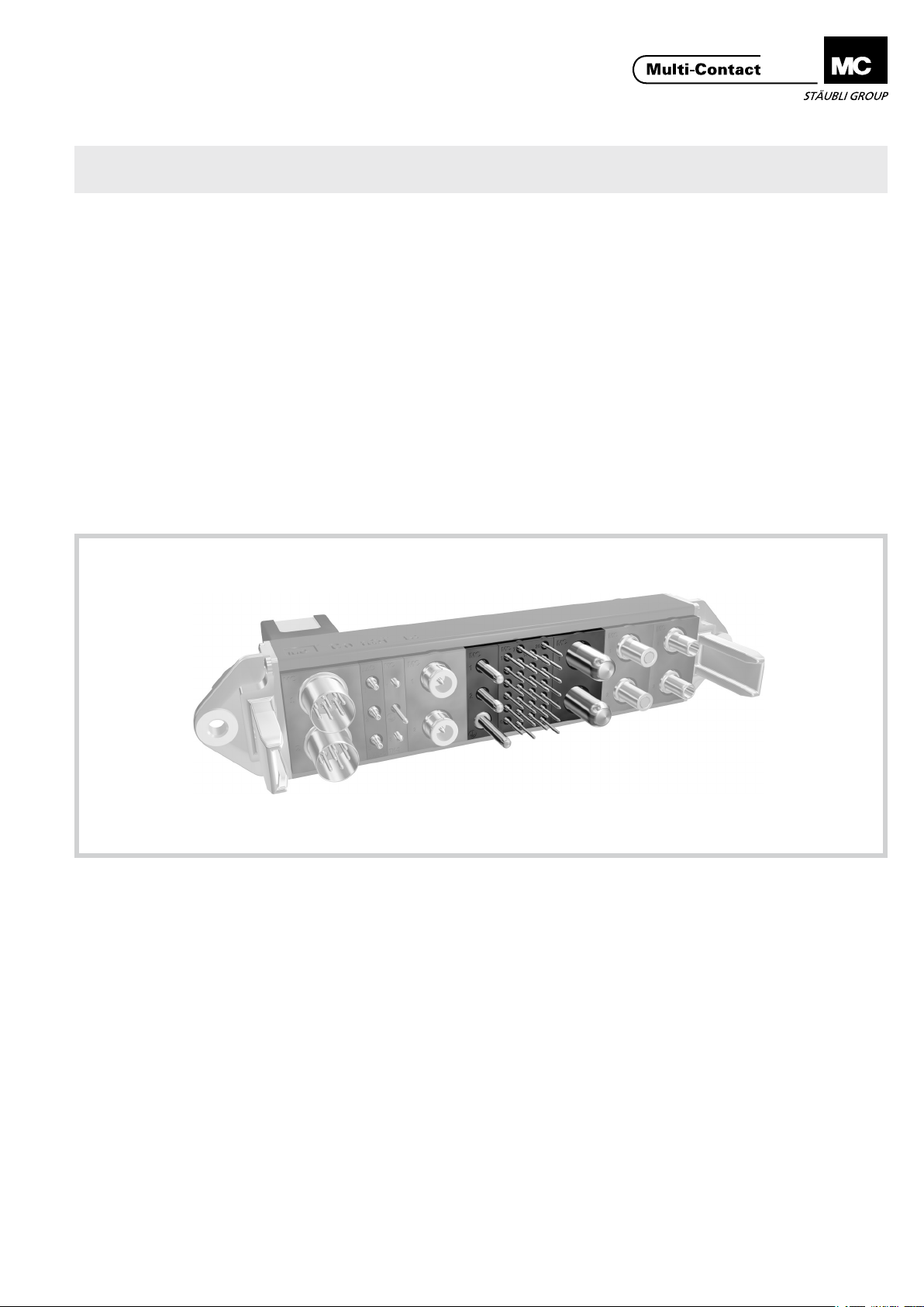
Advanced Contact Technology
MA213-01 (es_en)
Instrucciones de montaje
MA213-01 (es_en)
Assembly instructions
Conectores eléctricos para MC CombiTac Electrical connectors for MC CombiTac
Índice
Instrucciones de seguridad ........................................................2
Herramientas necesarias �����������������������������������������������������������3
Preparación de los cables ����������������������������������������������������������5
Montaje de los cables ����������������������������������������������������������������6
Plantillas para taladrar según la disposición
de los contactos PCB ����������������������������������������������������������������8
Montaje de los contactos ����������������������������������������������������������9
Montaje de tapones de obturación �����������������������������������������11
Vericación del montaje ����������������������������������������������������������11
Medidas de control de los contactos montados ���������������������12
Content
Safety Instructions ......................................................................2
Tools required ����������������������������������������������������������������������������3
Cable preparation ����������������������������������������������������������������������5
Cable assembly �������������������������������������������������������������������������6
Drilling plans PCB contacts �������������������������������������������������������8
Contact assembly ����������������������������������������������������������������������9
Assembly of blind plugs ����������������������������������������������������������11
Checking the contact assembly ����������������������������������������������11
Control dimensions of assembled contacts ����������������������������12
www.multi-contact.com 1 / 12
Page 2
Advanced Contact Technology
Instrucciones de seguridad Safety instructions
Sólo personal adecuadamente cualicado y especialistas formados podran realizar el montaje y la instalación de los productos teniendo en cuenta todas las regulaciones de seguridad aplicables�
Multi-Contact (MC) no se responsabiliza ante el incumplimiento de estas advertencias�
Utilice sólo los componentes y herrmientas indicadas por MC�
No se desvíe de los procedimientos de preparación y montaje
aquí descritos, en caso de una manipulación inadecuada no
se podrá garantizar la seguridad ni la conformidad con los da-
tos técnicos. No modique el prodcuto en ningún caso.
Los conectores no fabricados por MC que se pueden conectar
con elementos MC, a veces denominados por los fabricantes
como „compatibles con MC“ no cumplen con los requisitos
para una conexión eléctrica segura y estable a largo plazo�
No pueden conectarse con elementos MC por motivos de seguridad� Por tanto, MC no se responsabilizará de los daños
surgidos por la conexión de conectores no autorizados por
MC con elementos MC�
Los trabajos aquí descritos no pueden ejecutarse
en piezas conectadas a la red y con tensión.
El producto nal debe proporcionar protección al
usuario frente a una descarga eléctrica.
Los conectores no pueden separarse estando cargados. Se permite la conexión y desconexión con
tensión.
Cada vez que el conector sea usado, éste debe ser
inspeccionado previamente por posibles defectos externos (particularmente en el aislante). Si hay alguna
duda para su seguridad, se debe consultar a un especialista o el conector debe ser reemplazado.
Los conectores en carcasa están protegidos contra el
agua conforme a la clase de protección IP informada
para el producto respectivo.
Se deben proteger ante la humedad y suciedad los
conectores no conectados. No se pueden conectar
conectores sucios.
The products may be assembled and installed exclusively by
suitably qualied and trained specialists duly observing all applicable safety regulations�
Multi-Contact (MC) does not accept any liability in the event of
failure to observe these warnings�
Use only the components and tools specied by MC. In case
of self-assembly, do not deviate from the preparation and assembly instructions as stated herein, otherwise MC cannot
give any guarantee as to safety or conformity with the technical data� Do not modify the product in any way�
Connectors not originally manufactured by MC which can
be mated with MC elements and in some cases are even
described as ”MC-compatible” by certain manufacturers do
not conform to the requirements for safe electrical connection with long-term stability, and for safety reasons must not
be plugged together with MC elements� MC therefore does
not accept any liability for any damages resulting from mating
such connectors (i�e� lacking MC approval) with MC elements�
The work described here must not be carried out
on live or load-carrying parts.
Protection from electric shock must be assured by
the end product (i.e. by the correctly assembled
plug connector) and by its user.
The plug connections must not be disconnected
under load. Plugging and unplugging when live is
permitted.
Each time the connector is used, it should previously
be inspected for external defects (particularly in the
insulation). If there are any doubts as to its safety, a
specialist must be consulted or the connector must
be replaced.
The plug connectors in the housing are protected
from water in accordance with the IP protection class
stated for the relevant product.
Unmated plug connectors must be protected from
moisture and dirt. The male and female parts must
not be plugged together when soiled.
Encontrará más detalles técnicos en el catálogo del
producto.
For further technical data please see the product cat-
alogue.
Explicación de los símbolos Explanation of the symbols
Advertencia de voltajes peligrosos
Advertencia de área de peligro Warning of a hazard area
Sugerencia o consejo útil Useful hint or tip
2 / 12 www.multi-contact.com
Warning of dangerous voltages
Page 3
Advanced Contact Technology
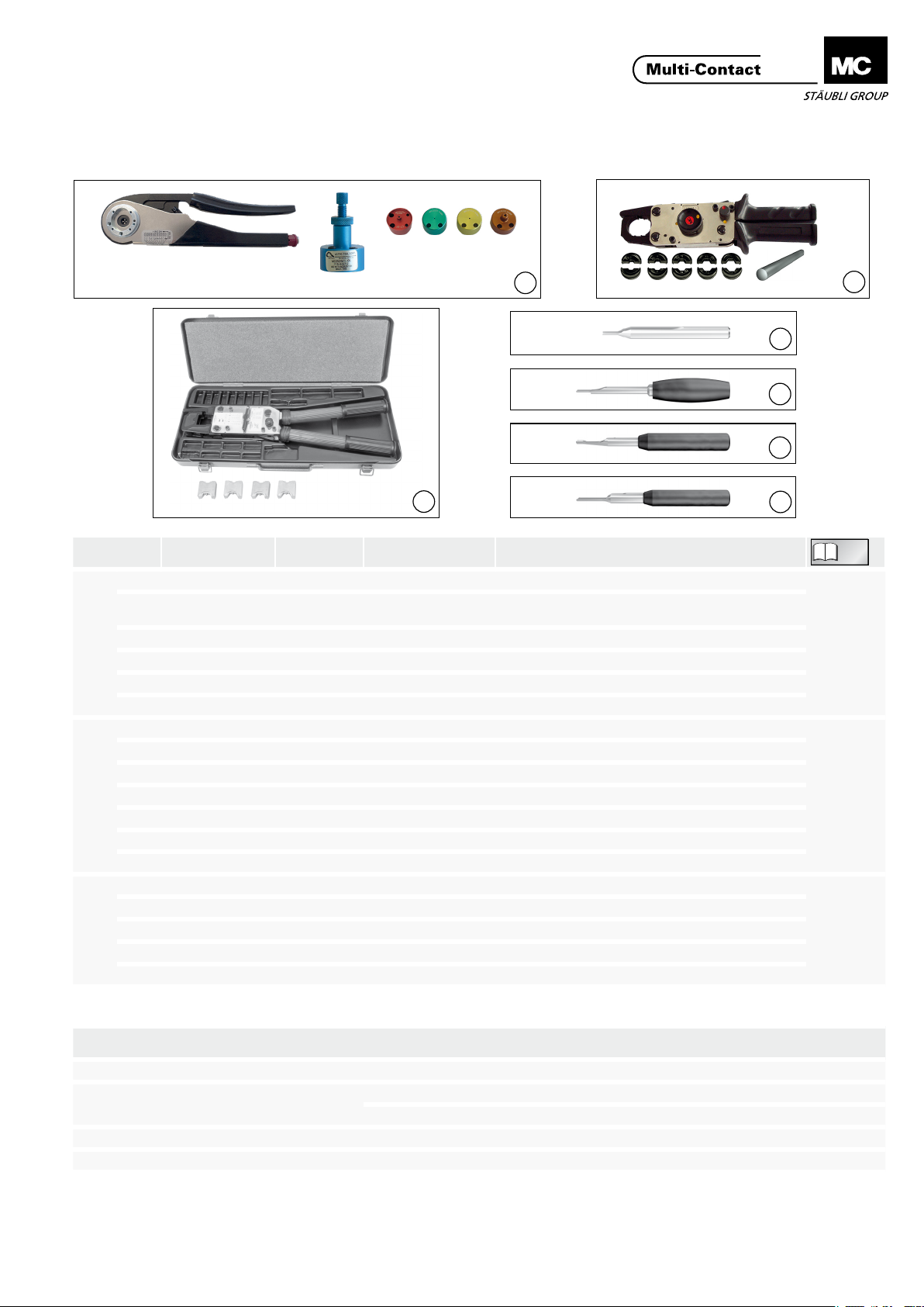
Herramientas necesarias Tools required
a b c d e g
f
1
h j k l m n
o
p
ill. Pos.
Tipo
Type
a CT-M-CZ 33.3800 Alicates de engarce / Crimping pliers
b MES-CZ 18.3801 0,14 – 4mm²
c MES-CZ-CT 0,6 18.3809 0,14 – 0,25mm² Casquillo de engarce / Insert
1
d MES-CZ-CT1 18.3804 0,25 – 0,75mm² Casquillo de engarce / Insert
e MES-CZ-CT1,5 18.3805 0,5 – 1,5mm² Casquillo de engarce / Insert
f MES-CZ-CT3 18.3806 2,5 – 4mm² Casquillo de engarce / Insert
g M-PZ13 18.3700 Alicates de engarce / Crimping pliers
h MES-PZ-TB5/6 18.3701 6mm² Casquillo de engarce / Insert
j MES-PZ-TB 8/10 18.3702 10mm² Casquillo de engarce / Insert
2
k MES-PZ-TB 9/16 18.3703 16mm² Casquillo de engarce / Insert
l MES-PZ-TB11/25 18.3704 25mm² Casquillo de engarce / Insert
m MPS-PZ13 18.3707 Matriz de prueba / Test insert
n MALU-PZ13 18.3708 Varilla redonda de prueba / Test round rod
o M-PZ-T2600 18.3710 Alicates de engarce con caja / Crimping pliers with box
p TB9-13 18.3712 16mm
3
TB11-14,5 18.3713 25mm
TB8-17 18.3711 10mm
TB7-20 18.3714 95mm
N° código
Order No.
Sección del conductor
Conductor cross section
3
Descripción
Description
Posicionador ajustable (excepto para contactos de Ø 0,6mm)
Locator adjustable (except for Ø 0,6mm contacts)
2
+ 35mm2Casquillo de engarce / Insert
2
+ 50mm2Casquillo de engarce / Insert
2
+ 70mm2Casquillo de engarce / Insert
2
Casquillo de engarce / Insert
Herramientas de montaja para
Insertion tool pin / socket
machos/hembras
Tipo
ill.
Type
4 CT-E-WZ0,6 33.3003 0,6mm
5 CT-E-WZ1-9,5 33.3001
6 ME-WZ1,5/2 18.3003 1,5mm
7 ME-WZ3 18.3010 3mm
N° código
Order No.
Ø nominal macho/hembra
for nominal Ø pin / socket
Contactos para termopar / Thermocouple contacts
1mm
2
4
5
6
7
e
i
c
g
r
a
h
a
n
t
t
m
i
n
l
g
e
u
o
e
i
z
t
n
u
M
n
d
E
e
g
n
i
n
n
.
u
i
s
e
a
t
n
z
i
b
d
e
h
s
c
I
I
n
m
u
.
b
s
e
h
M
d
e
c
t
i
i
o
n
k
m
m
g
u
t
e
d
e
n
t
o
l
l
t
e
l
r
-
o
i
P
s
s
t
n
d
a
i
e
M
s
r
a
e
a
P
i
d
n
r
o
w
n
b
d
a
z
i
s
u
c
m
t
k
h
f
r
i
t
e
o
r
n
v
v
h
e
e
k
c
r
b
l
e
S
,
i
n
n
e
,
s
h
t
e
h
n
a
i
d
g
l
e
t
a
e
b
r
s
e
h
w
d
t
c
a
I
ä
e
n
!
r
p
n
t
t
s
v
e
g
o
d
r
a
n
l
e
n
l
e
e
z
b
w
a
r
r
e
o
a
d
k
k
d
,
i
t
r
e
e
n
u
n
z
M
e
s
e
M
A
s
e
i
l
o
e
d
a
n
w
u
n
t
n
z
i
n
a
H
g
t
e
u
g
MA
MA079
MA224
MA226
www.multi-contact.com 3 / 12
Page 4
Advanced Contact Technology
Herramientas de montaje para machos / hembras
8
Descripción
ill.
Description
9
10
11
12
13
14
15
8 ME-WZ5 18.3013
9 MSA-WZ5
1) 3)
10 ME-WZ6 18.3016 8mm
11 MBA-WZ5
12 MSA-WZ6
2)
3)
13 MSA-WZ8 18.3022 8mm (M8A/PE-L)
1)
se usarán también para el montaje de tapones
2)
para contactos con conexion por tornillo con
rosca interior
3)
para contactos con conexion por tornillo con
rosca exterior
Herramienta extractora macho Pin extraction tool
Descripción
ill.
Description
14 CT-A-WZ0,6 33.3002 0,6mm
Insertion tool pin / socket
N° Código
Order No.
18.3015 6mm
18.3014 6mm / 8mm
18.3018 8mm
1)
will be used also for assembly of blind plugs
2)
for contacts with screw connection with inter
nal thread
3)
for contacts with screw connection with exter
nal thread
N° Código
Order No.
15 MSA-WZ1/1,2 18.3002 1mm
16
16 MSA-WZ1,5 18.3005
17 MSA-WZ3 18.3012 3mm
17
18 MSA-WZ6 18.3018
19 MSA-WZ8 18.3022 8mm / PE-L
18
Ø nominal macho/hembra
for nominal Ø pin / socket
6mm + CT-POF/SL
Contactos coaxiales/ Coaxial contacts
Ø nominal macho
for nominal Ø pin
Contactors para termopar
Termocouple contacts
1,5mm
6mm + CT-POF/SL
Contactos coaxiales/ Coaxial contacts
19
Herramienta extractora hembra Socket extraction tool
20
21
Descripción
ill.
Description
20 CT-A-WZ0,6 33.3002 0,6mm
N° Código
Order No.
21 MBA-WZ1/1,2 18.3001 1mm
22
22 MBA-WZ1,5 18.3004
23 MBA-WZ3 18.3011 3mm
23
24
24 MBA-WZ6 18.3017 6mm / 8mm
Ø nominal hembra
for nominal Ø socket
Contactors para termopar
Termocouple contacts
1,5mm
4 / 12 www.multi-contact.com
Page 5

Advanced Contact Technology
25
26
27
Descripción
ill.
Description
Ø nominal / Nominal Ø
Llave dinamométrica
para tornillos de cabeza
hexago
25
Torque wrench
gonal socket head screw
Llave dinamométrica
26
Torque wrench
Llave ja
27
Open-end spanner
1)
1)
1)
L
1)
for hexa-
1)
1)
Aplicación
Used for
Montaje del terminal de
cables Ø contactos 8mm
y 6mm
Fitting cable lug on Ø
8mm and Ø 6mm con-
tacts
Mont. d. terminal de cables
Fitting cable lug
Mont. d. terminal de cables
Fitting cable lug
*
contactos de puesta a tierra en avance para los
contactos de 12mm
1)
Puede adquirirse en el mercado
2)
para roscas internas y externas
3)
sólo para tornillos de acero
Preparación de los cables Cable preparation
Nota:
Comprobar que los contactos no
sufren esfuerzos de tracción por los
cable montados (Freno de cable).
Dimensión de la llave
Key size
mm mm
Ø 12
Ø 8
(PE-L)*
Ø 8 Ø 6
Ø 12
(M10)
- - 3Nm
8 - 5 4
44Nm
13 10 8 6Nm
15 10 8 7
*
leading earth contacts for the 12mm contacts
1)
Parts available commercially
2)
For internal and external thread
3)
Only for steel screws
are exerted on the contacts via assembled leads (Cable strain relief).
Par
Tightening torque
Ø 8
(PE-L)*
(M8)
3)
- 8,5Nm3)5Nm
Ø 8
(M6)
3Nm
2)
8,5Nm
Ø 6
(M5)
2)
2Nm
2)
2Nm
3)
5Nm
Note:
Make sure that no pulling forces
2)
3)
2)
3)
L 1
(ill. 28)
Colocar los accesorios en el cable, por
ejemplo, el prensaestopas� Pelar el
28
cable y cada uno de los conductores�
La cota L se determinará denitivamente cuando se haga el montaje en
la caja y en cada caso� Ver MA213� La
cota L1 que conviene dejar cuando
se pela cada uno de los conductores,
(ill. 28)
Place accessories (e�g� cable gland)
on the cable� Strip cable and single
conductors�
Dimension L of the cable for installation in housing has to be adapted
from case to case, see MA213�
Dimension L1 for single conductors,
see Tab� 1, page 6�
está indicada en la tabla ver Tab�1,
página 6�
www.multi-contact.com 5 / 12
Page 6

Advanced Contact Technology
Tab. 1
Nom. Ø macho/hembra
Nominal Ø pin / socket
mm mm
Contactors para termopar
Thermocouple contacts
(DBP2-/DSP2/CT-BP1/CT-SP1)
0,6 0,14 26 26 1 MES-CZ-CT 0,6 - - 5
0,6 0,25 24 24 2 MES-CZ-CT 0,6 - - 5
1 0,25 24 24 2 MES-CZ-CT1 - - 4,5
1 0,5 20 20 4 MES-CZ-CT1 - - 4,5
1 0,75 18 18 5 MES-CZ-CT1 - - 4,5
1,5 0,5 20 20 4 MES-CZ-CT1,5 - - 4,5
1,5 1 18 18 5 MES-CZ-CT1,5 - - 4,5
1,5 1,5 16 16 6 MES-CZ-CT1,5 - - 4,5
3 2,5 14 14 7 MES-CZ-CT3 - - 8
3 4 12 12 8 MES-CZ-CT3 - - 8
6 6 10 - - - MES-PZ-TB-5/6 - 10
6 10 8 - - - MES-PZ-TB-8/10 TB8-17 10
6 16 6 - - - MES-PZ-TB-9/16 TB9-13 10
8 10 8 - - - MES-PZ-TB-8/10 TB8-17 10
8 16 6 - - - MES-PZ-TB-9/16 TB9-13 10
8 25 4 - - - MES-PZ-TB-11/25 TB11-14,5 10
8 35 2 - - - - TB9-13 12
8 50 1/0 - - - - TB11-14,5 23
12 50 1/0 - - - - TB11-14,5 23
12 70
12 95
2)
Sección del conductor
Conductor cross section
2
0,14 26 26 1 MES-CZ
0,2 24 24 2 MES-CZ
0,34 22 22 3 MES-CZ
0,5 20 20 4 MES-CZ
2)
2)
2x
AWG
2/0 - - - - TB8-17 26
3/0 - - - - TB20 28
CT-M-CZ M-PZ-13 M-PZ-T2600
Selector
AWG-No
1)
El posicionador MES-CZ puede usarse también
para Ø nominales de 1mm hasta 3mm.
Selector
SEL-No
Alicates de engarce / Crimping pliers
Casquillo.engarce
Locator
1)
1)
1)
1)
Casquillo de engarce
Insert
- - 4,5
- - 4,5
- - 4,5
- - 4,5
1)
The locator MES-CZ can also be used for nomi-
nal Ø pin/socket from 1mm up to 3mm.
Casquillo de engarce
Insert
L1
mm
min.2
min.2
max.21
Agujero de control
Sight hole
(ill. 29)
2)
En terminaciones crimpeadas con una sección
transversal de conductor de 70mm
deben hacerse dos compresiones una al lado
de la otra�
2
o 95mm2,
(ill. 29)
2)
In crimp terminations with a conductor cross-
section of 70mm
must be performed side by side�
Montaje de los cables Cable assembly
29
Conexión por engarce Crimp connection
Alicate y casquillos de engarce según
Tab� 1�
(ill. 30)
Introducir el conductor unipolar en
el casquillo de engarce hasta el tope�
Proceder al engarce manteniendo
apretado el conductor en sentido axial
dentro del casquillo�
30
Nota:
Para contactos con Ø nominal de
0,6mm, 1mm, 1,5mm y 3mm:
Antes y después del engarce deben
verse los hilos del conductor a través
del agujero de control. (ill. 31).
31
Nota:
Despues de conectar el cable, la
zona de crimpado debe aislarse con
una funda termoretráctil, pedido Nº
33.5666.
Crimping pliers and insert according
to Tab� 1�
(ill. 30)
Insert wire into the contact crimping
sleeve as far as it will go�
Hinweis:
For contacts with nominal
Ø 0,6mm, 1mm, 1,5mm and
3mm: Wires must be visible in the
sight hole before and after crimping
(ill. 31).
Note:
After connecting the cable, the
crimp area must be insulated with
the shrink-on sleeve, order No.
33.5666.
2
or 95mm2, two pinches
6 / 12 www.multi-contact.com
Page 7

Advanced Contact Technology
Conexión por tornillo Screw termination
(Para montaje de terminales de
cable, tamaño máximo 95mm²
según DIN 46234).
Bajo demanda, MC puede suminis-
trar terminales de 35mm
2
70mm
CT-KSCH6-35, código 33�4039
K-SCH50-10, código 33001501
CT-K-SCH70-10, código 33�4114
CT-K-SCH95-10, código 33�4115
y 95mm2:
2
, 50mm2,
(For cable lug assembly, max. size
95mm
MC can supply a cable lug for a cable
cross section of 35mm
70mm
CT-KSCH6-35, Order no� 33�4039
K-SCH50-10, Order no� 33001501
CT-K-SCH70-10, Order no� 33�4114
CT-K-SCH95-10, Order no� 33�4115
2
according to DIN 46234).
2
and 95mm2:
2
, 50mm2,
(ill. 32)
Conexión con rosca exterior M5,
M6, M8:
Montar el terminal (a), la arandela
plana (b), la arandela dentada (c) y
la tuerca hexagonal (d) siguiendo el
32
orden indicado� Con la llave dinamométrica apretar la tuerca (d) sujetando
el contacto con una llave ja en la
posición X Par de apriete máximo:
M6: 3Nm, M5: 2Nm, M8: 6Nm
(ill. 33)
Conexión con rosca interior M5,
M6, M10:
Montar el terminal (a), la arandela
plana (b), la arandela dentada (c) y
el tornillo Allen de cabeza cilíndrica
33
M6x12 (d) y M5x12 y M10x20 en el
orden indicado� Apretar el tornillo
Allen (d) con la llave dinamométrica
sujetando el contacto con una llave
ja en la posición X.
Par de apriete máximo:
M5:
5Nm (2Nm con tornillos de latón)
M6:
8,5Nm (3Nm con tornillos de latón)
M10:
44Nm
(ill. 32)
Connection with external thread
M5, M6, M8:
Install cable lug (a), washer (b), lock
washer (c) and the nut (d)� Tighten
the nut (d) with a torque wrench and
secure it with an open-end spanner at
pos� X�
Max� tightening torque:
M6: 3Nm, M5: 2Nm, M8: 6Nm
(ill. 33)
Connection with internal thread
M5, M6, M10:
Install the cable lug (a), washer (b),
lock washer (c) and hexagon sockethead screw M6x12 (d) or M5x12 or
M10x20 in the order shown�
Tighten the hexagon socket-head
screw (d) with a torque wrench and
secure it with an open-end spanner at
pos� X�
Max� tightening torque:
M5:
5Nm (2Nm with brass screws)
M6:
8,5Nm (3Nm with brass screws)
M10:
44Nm
Nota:
Una vez conectado el cable, es
34
www.multi-contact.com 7 / 12
preciso aislar los terminales con una
funda termo-retráctil (S) (ill. 34).
Note:
After cable assembly, the cable
lugs should be insulated with a
shrink sleeve (S) (ill. 34).
Page 8

Advanced Contact Technology
Plantillas para taladrar según la
disposición de los contactos PCB
Las caras de conexión macho y
hembra son idénticas
Nota:
Temp. máx. de soldadura: 260°C
Tiempo máx. de soldadura: 3 seg.
El material con el que están fabricados los porta-contactos es resistente
al tricloretileno.
Vista: cara de la conexión por
enchufe
A = CT-E1-26
B = CT-E3-3
C = CT-E1-6
D = CT-E1-15
E = CT-E1,5-5
F = CT-E0,6-20
Drilling plans PCB contacts
Male and female connecting face
are identical
Hinweis:
Max. soldering temp.: 260°C
Max. soldering time: 3 seconds.
Material of contact carrier, is resistant
to the cleaning uid trichloroethylene.
Connecting face view
Separaciones entre agujeros, tolerancia: ±0,1
Distance between holes, tolerance: ±0,1
8 / 12 www.multi-contact.com
Page 9

Advanced Contact Technology
Montaje de los contactos Contact assembly
(ill. 35 – 40)
Colocar los contactos (con el calbe
conectado) en el porta-contactos
utilizando las herramientas de montaje
apropiadas (ver Tab� 2, página 10)�
Para facilitar el montaje de los contac-
tos de Ø 8mm y Ø 6mm, humedecer
los porta-contactos con alcohol de
uso industrial�
(ill. 35 – 40)
Insert the contacts (with connected
lead) in the contact carrier by means
of the inserting tools according to
Tab� 2, page 10� The insertion of the
Ø 8mm and Ø 6mm contacts can be
facilitated by previously wetting the
contact carriers with industrial alcohol�
35 36
Nota:
Para no estropear los porta-contactos
es necesario poner las herramientas de
montaje en posición paralela al eje de
cada uno de los contactos. Con los con-
tactos de Ø 1mm se habrá alcanzado la
posición correcta de montaje en profundidad cuando el resalte de la herramienta
haga tope con el porta-contactos.
Hinweis:
To avoid damage to the contact
carriers, the inserting tools must be
guided parallel to the axis.
In the case of the Ø 1mm contacts the correct insertion depth is
obtained by pressing the contacts in
until the shoulder of the insertion tool
comes up against the contact carrier.
Tab. 2 Tab. 2
37
38
ill.
35 1
Contactos con Ø nom. (mm)
Contact with nom.-Ø (mm)
1)
con engarce
x - - CT-E-WZ1-9,5 33.3001
with crimp connection
con conexión por
soldadura
with solder connection
con attacco a vite
with screw connection
Herramientas de montaje
Insertion tool
N° de Código
Order No.
36 1,5 x - - ME-WZ1,5/2 18.3003
37 3 x - - ME-WZ3 18.3010
6 x - - ME-WZ5 18.3013
38
8 x - - ME-WZ6 18.3016
39 40
4)
8
6 - - x
39
6 / 8 - - x
40 8 - - x
0,6 x - -
41a
41b
0,6 - - x
1)
Utilizados también para contactos termopar
2)
Rosca interior M5 or M6
3)
Rosca exterior M5 or M6, M8
4)
Para 8mm PE-L
x - - MSA-WZ8 18.3022
3)
2)
3)
MSA-WZ5 18.3015
MBA-WZ5 18.3014
MBA-WZ6 18.3018
CT-E-WZ0,6 33.30030,6 - x -
1)
Also used for thermocouple contacts�
2)
Internal thread M5 or M6
3)
External thread M5 or M6, M8
4)
For 8mm PE-L
www.multi-contact.com 9 / 12
Page 10

Advanced Contact Technology
41a
D
(ill. 41a)
Instalación CT-0.6
Usando la herramienta de montaje
CT-E-WZ0�6, introduzca por presión
los contactos en las piezas insertables
desde la cara trasera numerada hasta
el tope�
(ill. 41b)
Extracción de CT-0,6
Inserte la herramienta de montaje CT-
A-WZ0,6 en la pieza insertable desde
el frente hasta que se escuche un clic�
Luego, si fuera necesario, presione
el pin (D) para extraer el contacto del
soporte�
Nota:
Para garantizar una rme jación
de los insertos, los contactos no
deben ser extraídos más de 2 veces
ni insertados más de 3.
D
41b
(ill. 41a)
Installation CT-0.6
Using the assembly tool CT-E-WZ0�6,
press the contacts into the contact
inserts from the numbered back side
as far as the stop�
(ill. 41b)
Removal of CT-0.6
Insert dismantling tool CT-A-WZ0,6
into the contact insert from the front
until a click is heard� Then, if necessary, push the pin (D) to extract the
contact from the carrier�
Note:
In order to quarantee a rm
xation of the contacts in the contact
carriers, the contacts may not be
extracted more than 2 times and
inserted more than 3 times.
(ill. 42)
Al montar el contacto de 12mm,
42
ambas marcas señaladas (M), deben
estar alineadas� El contacto está en-
tonces insertado en su posición nal
(puede ser insertado en ambos lados)
y asegurado por el clip de anclaje
mediante un “clic”�
Nota:
Saliente en posición de inserción:
2mm (ill. 43)
El clip de anclaje puede ser retirado
cin un destornillador (tamaño 2)�
43
10 / 12 www.multi-contact.com
(ill. 42)
When mounting the 12mm contact
with external thread, the markings on
both the carrier and the contact must
be aligned� The contact is then inserted to the end position (can be inserted
in both side) and secured with retaining clip� Engaging by audible clic�
Note:
Height in inserted condition: 2mm
(ill. 43)
The retaining clip can be removed
with a commercial screwdriver
(size 2)�
Page 11

Advanced Contact Technology
Ejemplo / Example: MVS1
Tapón de obturación
Blind plug
3.3
5.2
Dirección de montaje
Mounting direction
Ø3 .5
(ill. 44)
Montaje de tapones de obtu-
(ill. 44)
Assembly of blind plugs
ración
Tab. 3 Tab. 3
44
Tapones de obturación
Blind plugs
CT-BS1 1 MSA-WZ-1/1,2 18.3002 3,5mm – 5,1mm
MVS1 1,5 MSA-WZ-1,5 18.3005 3,3mm – 5,2mm
MVS3 3 MSA-WZ-3 18.3012 1mm – 1,6mm
MVS5 6 MSA-WZ-5 18.3015 7,5mm – 8,7mm
CT-BS8 8 MSA-WZ-8 18.3022 2mm
Ø
Herramienta extractora / de inserción
Insertion / Extraction tool
N° de Código
Order No.
Vericación del montaje Checking the contact assembly
Dimen. de control
Control dimension
(ill. 45)
Comprobar el correcto montaje de
los contactos vericando las cotas X1
X 2
X 1
(para machos), X2 (para avanzados
machos) y X3 (para hembras)�
(ver Tab� 4, página 12)
7. 9
Con el CT-0,6 los contactos quedan
correctamente sujetados en los soportes presionando con la herramienta
adecuada en las partes de contacto
(ill. 45)
The correct engagement of the
contacts must be checked with the
dimensions X1 (pin), X2 (pin, premating) and X3 (sockets)�
(See Tab� 4, page 12)�
With the CT-0,6 the contacts are correctly locked in the carriers by pressing in the contact parts as far as they
will go with the appropriate tool�
hasta que lleguen al tope�
En caso de un error de montaje,
avería o reparación, pueden extraerse
los contactos por el mismo lado de
7. 9
X 3
conexión del portacontactos utilizando
herramientas adecuadas y volver a
colocarlos correctamente� (ver herra-
In the event of pin or socket assignment errors or repairs the contacts
are pushed out of the contact carriers
from the plugging side using the appropriate extraction tools and reinserted (extraction tools see page 4)�
mientas en página 4)�
45
www.multi-contact.com 11 / 12
Page 12

Advanced Contact Technology
Medidas de control de los
contactos montados
Control dimensions of assembled contacts
Tab. 4
Longitud del macho
Pin length
Ø nom. de macho / hembra
Nom.-Ø pin / socket
mm mm mm mm mm mm
1 10,4 11,4 - 11,7 1,5 10,4 12,4 - 12,1 3 12 13 17 13 17
6 15 - 21 16,5 21
8 15 - 21 15 21
8 (PE-L) - - 28 - 28
12 22 - - 26 Contactos para termopar
Thermocouple contacts
X1 X2 X3 X3
4,3 - 10,4
Longitud macho avanzado
Pin length, premating
Longitud del macho PE
PE.pin length
als ras del porta contactos
ush with contact carriers
Profundidad de la hembra
Socket depth
12,1
Profundidad hembra PE
PE socket depth
Fabricante/Producer:
Multi-Contact AG
Stockbrunnenrain 8
CH – 4123 Allschwil
Tel. +41/61/306 55 55
Fax +41/61/306 55 56
mail basel@multi-contact.com
www.multi-contact.com
© by Multi-Contact AG, Switzerland – MA213-01 – 06.2014, Index k, Global Communications – Sujeto a modicaciones / Subject to alterations
 Loading...