

Page 1
Advanced Contact Technology
MA000 (de_en)
MA202 (es_en)
Montageanleitung
Instrucciones de montaje
Montaje de contactos macho y hembra en
conectores multipolares desde 2 polos + PE
hasta 109 polos + PE
Índice
Instrucciones de seguridad ........................................................2
Herramientas necesarias �����������������������������������������������������������3
Preparación del cable ����������������������������������������������������������������4
Engarce de los contactos ����������������������������������������������������������6
Montaje de los contactos ����������������������������������������������������������7
Comprobación de que el montaje es correcto ��������������������������8
MA000 (de_en)
MA202 (es_en)
Assembly instructions
Assembly instructions
MC Multipole pin and socket inserts 2-pole+PE
up to 109-pole+PE
Content
Safety Instructions ......................................................................2
Tools required ............................................................................3
Cable preparation ����������������������������������������������������������������������4
Crimpen der Kontakte ����������������������������������������������������������������6
Einbau der Kontakte ������������������������������������������������������������������7
Control of correct assembly ������������������������������������������������������8
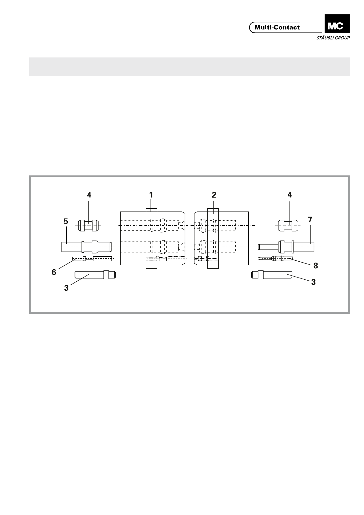
1. Soporte de hembras
2. Soporte de machos
3. Tapón ciego MVS1/1
4. Tapón ciego
2)
1)
5. Hembra Ø 5-11mm
6. Hembra Ø 1-3mm
7. Macho Ø 5-11mm
8. Macho Ø 1-3mm
1)
En la referencia E01-18PE no puede utilizarse un tapón ciego� En su lugar esta
permitido reemplazarlo con todos los contactos� El tapón ciego debería montarse con la parte mas larga en dirección hacia la entrada del cable� La conexión con este conector únicamente esta disponible para la ref� E1-18+PE (pin +
zócalo)�
2)
Adecuado para diámetro nominal Ø 1,5 - 8mm Colores: Ø1/blanco, Ø1,2-2/
azul; Ø 2,36 y 3/amarillo; Ø5/blanco; Ø6/negro; Ø8/negro
www.multi-contact.com 1 / 8
1. Socket carrier
2. Pin carrier
3. Blind plugs MVS1/1
4. Blind plugs Ø 1-8
1)
2)
5. Socket Ø 5-11mm
6. Socket Ø 1-3mm
7. Plug Ø 5-11mm
8. Plug Ø 1-3mm
1)
The blind plug MVS1/1, suitable for nominal Ø 1mm, must be assembled with
the long side facing the direction of the cable entry� The blind plug is only
suitable for the E1-18+PE (Pin + socket side)� For the E01-18PE a blind plug
may not be used. In place of this it is permitted to completely ll the part with
all contacts�
2)
Suitable for nominal-Ø 1,5 - 8mm Colours: Ø1/white; Ø1,2-2/blue; Ø 2,36 and
Ø3/yellow; Ø5/white; Ø6/black; Ø8/black
Page 2
Advanced Contact Technology
Instrucciones de seguridad Safety instructions
Solo personal adecuadamente cualicado y especialistas formados podrán realizar el montaje y la instalación de los productos, teniendo en cuenta todas las regulaciones y normas
de seguridad legales aplicables�
Multi-Contact (MC) no se responsabiliza del incumplimiento
de estas advertencias�
Utilice solo los componentes y las herramientas indicados
por MC� No se desvíe de los procedimientos de preparación y
montaje aquí descritos� En caso de una manipulación inadecuada, no se podrá garantizar la seguridad ni la conformidad
con los datos técnicos. No modique el producto en ningún
caso�
Los conectores no fabricados por MC que se pueden conectar
con elementos MC, a veces denominados por los fabricantes
como "compatibles con MC", no cumplen con los requisitos
para una conexión eléctrica segura y estable a largo plazo, por
lo que, por motivos de seguridad, no pueden conectarse con
elementos MC� Por tanto, MC no se responsabilizará de los
daños causados por la conexión de conectores no autorizados
por MC con elementos MC�
Los trabajos aquí descritos no pueden llevarse a
cabo en piezas conectadas a la red o con tensión.
El producto nal (conectores congurados correctamente) debe proporcionar protección ante una
descarga eléctrica. El usuario mismo debe asegurar la protección.
Los conectores no pueden separarse estando cargados. Se permite la conexión y desconexión con
tensión.
Antes de cada uso debe comprobarse (particularmen-
te el aislante) de que no haya posibles defectos externos. En caso de duda sobre la seguridad, se debe
consultar a un especialista o el conector debe ser reemplazado.
Los conectores son impermeables según el tipo de
protección IP indicado para cada producto.
Los conectores no conectados deben protegerse ante
la humedad y suciedad. Los conectores ensuciados
no deben conectarse entre sí.
The products may be assembled and installed exclusively by
suitably qualied and trained specialists duly observing all applicable safety regulations�
Multi-Contact (MC) does not accept any liability in the event of
failure to observe these warnings.
Use only the components and tools specied by MC. In case
of self-assembly, do not deviate from the preparation and as-
sembly instructions as stated herein, otherwise MC cannot
give any guarantee as to safety or conformity with the technical data. Do not modify the product in any way.
Connectors not originally manufactured by MC which can
be mated with MC elements and in some cases are even
described as ”MC-compatible” by certain manufacturers do
not conform to the requirements for safe electrical connec-
tion with long-term stability, and for safety reasons must not
be plugged together with MC elements. MC therefore does
not accept any liability for any damages resulting from mating
such connectors (i.e. lacking MC approval) with MC elements.
The work described here must not be carried out
on live or load-carrying parts.
Protection from electric shock must be assured by
the end product (i.e. by the correctly assembled
plug connector) and by its user.
The plug connections must not be disconnected
under load. Plugging and unplugging when live is
permitted.
Each time the connector is used, it should previous-
ly be inspected for external defects (particularly the
insulation). If there are any doubts as to its safety, a
specialist must be consulted or the connector must
be replaced.
The plug connectors are watertight in accordance
with the product specic IP protection class.
Unmated plug connectors must be protected from
moisture and dirt. The male and female parts must
not be plugged together when soiled.
Encontrará más detalles técnicos en el catálogo del
producto.
For further technical data please see the product cat-
alogue.
Explicación de los símbolos Explanation of the symbols
Advertencia de voltajes peligrosos
Advertencia de área de peligro Warning of a hazard area
Sugerencia o consejo útil Useful hint or tip
2 / 8 www.multi-contact.com
Warning of dangerous voltages
Page 3
Advanced Contact Technology
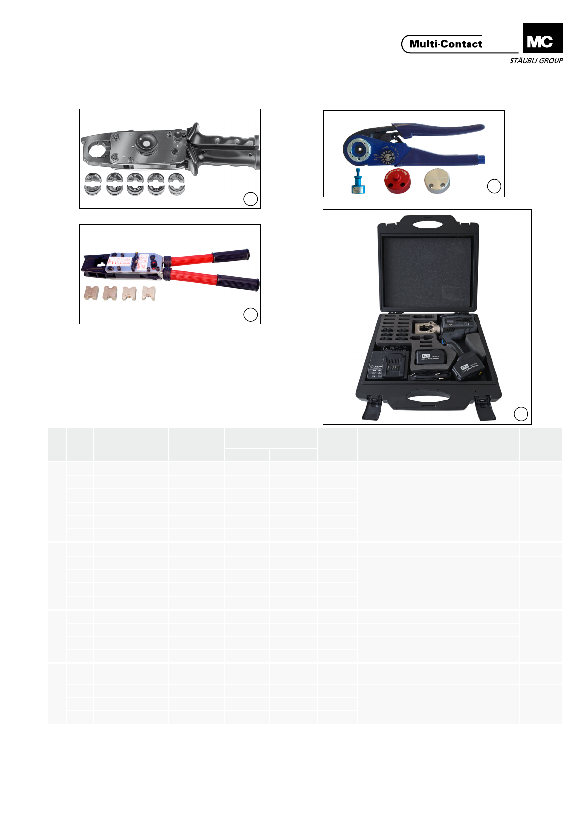
Herramientas necesarias Tools required
a
b c d e f
1
l
m
n o
g
h i j k
2
Tab. 1
Sección del conductor
Conductor cross-section
mm
2
AWG
L± 0,5
Descripción
Description
Casquillo de engarce / Insert for a
Casquillo de engarce / Insert for i
Casquillo de engarce / Insert for n
- - - Maletín para crimpadoras / Crimping tool case
Casquillo de engarce / Insert for pliersMBT 13-35-50 18.3024 35 2(1) 15
2
1)
Crimping pliers up to 35mm2 max�
2)
Each insert can be used on 2 sides� Numerals 8 + 17, 9 + 13, 11 + 14,5 =
outer-Ø of crimping sleeves�
3)
For pilot contacts�
ill. Pos.
a M-PZ13
Tipo
Type
1)
N° de código
Order No.
18.3700 - - Alicates de engarce / Crimping pliers
b MES-PZ-TB 5/6 18.3701 6 - 10
c MES-PZ-TB 8/10 18.3702 10 - 12
1
d MES-PZ-TB 9/16 18.3703 16 6 12
e MES-PZ-TB 11/25 18.3704 25 4 14
f MES-PZ-TB 13/35 18.3705 35 2;(1) 15
g M-PZ-T2600 18.3710 - - - Alicates de engarce / Crimping pliers
h TB8-17
2
i TB9-13
j TB11-14,5
2)
2)
2)
18.3711 10 + 70 2)7 + 00 10/25
18.3712 16 + 35 2)6 + 2 (1) 12/15
18.3713 25 + 50 2)4 + 1 14/22
k TB20 18.3714 95 000 27
l M-CZ
m MES-CZ 18.3801 - - - Localizador
3
n MES-CZ1,5/2 18.3802 0,5 – 1,5 - 7
3)
18.3800 - - - Alicates de engarce / Crimping pliers
o MES-CZ1/1,57 18.3803 0,25 – 1,5 - 57
CZK2-230
CZK2-110
4
MBT 11-25-50 18.3023 25 4 14
18.3111
18.3112
MBT 14,5-50-50 18.3025 50 1 22
1)
Alicates de engarce de uso adecuado hasta 35mm
2)
Suplementos de uso por ambos lados� Numeración 8 + 17, 9 +
13, 11 + 14,5 = diámetro de los casquillos de engarce
3)
Para los contactos piloto�
3
4
e
i
c
g
r
a
h
a
n
t
t
m
i
n
l
g
e
u
o
e
i
z
t
n
u
M
n
d
E
e
g
n
i
n
n
.
u
i
s
e
a
t
n
z
i
b
d
e
h
s
c
I
I
n
m
u
.
b
s
e
h
M
d
e
c
t
i
i
o
n
k
m
m
g
u
t
e
d
e
n
t
o
l
l
t
e
l
r
-
o
i
P
s
s
t
n
d
a
i
e
M
s
r
a
e
a
P
i
d
n
r
o
w
n
b
d
a
z
i
s
u
c
m
t
k
h
f
r
i
t
e
o
r
n
v
v
h
e
e
k
c
r
b
l
-
e
S
,
i
n
n
e
,
s
h
t
e
h
n
a
i
d
g
l
e
t
a
e
b
r
s
e
h
w
d
t
c
a
I
ä
e
n
!
r
p
n
t
t
s
v
e
g
o
d
r
a
n
l
e
n
l
e
e
z
b
w
a
r
r
e
o
a
d
k
k
d
,
i
t
r
e
e
n
u
n
z
M
e
s
e
M
A
s
e
i
l
o
e
d
a
n
w
u
n
t
n
z
i
n
a
H
g
t
e
u
g
MA
MA224
MA226
MA085
MA306
www.multi-contact.com 3 / 8
Page 4

Advanced Contact Technology
Herramienta de montaje para
ill.
macho/hembra
Insertion tool pin/socket
N° de código
Order no.
Per Ø nominale spina/boccola
For nom.-Ø pin/socket
ME-WZ1/1,2 18.3000 1 / 1,2
ME-WZ1,5/2 18.3003 1,5 / 1,57 / 2 / 2,36
ME-WZ3 18.3010 3
5
ME-WZ5 18.3013 5
5
ME-WZ6 18.3016 6
ME-WZ11/38 18.3021 8 / 11
Herramienta de extracción (macho)
ill.
Extraction tool pin
N° de código
Order no.
Para Ø nominal
For nom.-Ø contact
MSA-WZ1/1,2 18.3002 1 / 1,2
MSA-WZ1,5 18.3005 1,5 / 1,57
MSA-WZ1,5/109 18.3020 1,5
1)
MSA-WZ2 18.3009 2
6
6
MSA-WZ3 18.3012 2,36 / 3
MSA-WZ5 18.3015 5
MSA-WZ6 18.3018 6
MSA-WZ8 18.3022 8
MBA-WZ5 18.3014 11
Herramienta de extracción (casquillos)
ill.
Extraction tool socket
N° de código
Order no.
Para Ø nominal
For nom.-Ø contact
MBA-WZ1/1,2 18.3001 1 / 1,2
MBA-WZ1,5 18.3004 1,5 / 1,57
MBA-WZ1,5/109 18.3019 1,5
MBA-WZ2 18.3008 2
7
7
MBA-WZ3 18.3011 2,36 / 3
1)
MBA-WZ5 18.3014 5
MBA-WZ6 18.3017 6
MSA-WZ8 18.3022 8
1)
Para conectores de 58 polos o de 109 polos
1)
For 58-pole or 109-pole connectors
Preparación del cable Cable preparation
(ill. 8)
Pelar el cable a la dimensión Lx� Determinar Lx de acuerdo con el tamaño
del cuerpo y la clase de cable� Valores
orientativos para cuerpo estándar MC:
Tamaño de cuerpo
8
4 / 8 www.multi-contact.com
Housing size
1 40
2 40
3 55
4 70
(ill. 8)
Strip cable insulation to dimension
Lx� Lx depends on housing size and
type of cable . Approximate gures for
standard MC housings:
Lx (mm)
Page 5

Advanced Contact Technology
(Tab. 1)
Tab. 1
Ø nominal macho/hembra
Nom-Ø pin/socket
mm mm
1 / 1,5 0,14 / 0,2 / 0,34 / 0,5 26 / 24 / 22 / 20 5 26 / 24 / 22 / 20 2 / 3 / 4
1,2 0,5 – 0,75 22 / 20 5 22 / 20 3 / 4
1,57 0,5 20 5 20 4
1 / 1,5 / 2
1,5 / 2 1,5 16 7 16 6
2 1,5 / 2,5 16 / 14 7 14 / 12 7 / 8
2,36 0,5 – 1,5 20 / 16 7 20 / 18 / 16 4 / 5 / 6
3
5 / 6
6 16 13 MES-PZ-TB9/16 TB9/13
6 / 8 25 15 MES-PZ-TB11/25 TB11-14,5 MBT11-25-50
8 / 11 35 15 MES-PZ-TB13/35 TB9-13 MBT13-35-50
11 38 18 MES-PZ-TB13/35
11 50 22 TB11-14,5 MBT14,5-50-50
Sección del conductor
Conductor cross-section
2
0,5 20 / 18 7 20 / 18 4 / 5
0,75 7 18 5
1 18 7 18 5
2,5 12 7 12 8
4 7 12 8
6 11 MES-PZ-TB6/5
10 13 MES-PZ-TB8/10
AWG mm AWG AWG
Pelar cada conductor a la dimensión L
L ± 0,5
Alicates de engarce M-CZ
Crimping pliers M-CZ
Selector
(Tab. 1)
Strip wire insulation to dimension L
Casquillo para M-PZ13
Insert for M-PZ13
Casquillo para M-PZ-T2600
Insert for M-PZ-T2600
Casquillo para CZK...
Insert zu CZK...
Sección del conductor
Conductor cross-section
2
mm
0,14 18/5
0,25 18/5
0,5 16/6
0,75 16/6
1,0 14/7
1,5 14/7
2,5 12/8
Posicion del selector
Selector position
Atención
Para realizar las conexiones de
los conectores macho y hembra
del conjunto ME3-36+PE ���2/2�5
se consideratá la dimensión L =
7 ± 0,5 y además se aplicarán los
siguientes ajustes del selector en
el alicate de engarce (MES-CZ)�
Para las secciones de conductor
de 0,14mm² hasta 1mm², se
necesitan casquillos reductores
para usar adicionalmente con
los casquillos de engarce� Son
de uso adecuado los terminales según normmaDIN 46228 /
sección nominal 1,0/longitud 6,
supercie plateada (p.e. los de la
rma Klauke tipo 72S/6).
Attention
For the connections of pin and
socket inserts ME3-36+PE���2/25
the size L is 7±0,5� For the selector position of the crimping tool
(MES-CZ) the following settings
have to be used and when working with cross-sections of
0,14mm
sary to use a reducing sleeve
in the crimp barrel� Wire end
ferrules accord� to DIN 46228
nom� cross-section 1,0/6 long
and silver plated are suitable for
this purpose� (e�g� Klauke type
72S/6)�
2
to 1mm2 it is neces-
www.multi-contact.com 5 / 8
Page 6

Advanced Contact Technology
Engarce de los contactos Crimping the contacts
Agujero de control
Control hole
Atención (ill. 9)
Si fuera necesario, antes de engarzar, pasar el cable a través del
prensa-estopas (Pg) y de la caja
de protección�
9
(ill. 10)
Cuando introduzca el manguito para
engastar en la herramienta, use la
zona de engaste (C)�
Introducir cada conductor, uno por
uno, en el casquillo de engarce del
contacto hasta alcanzar el tope� Cada
uno de los conductores debe verse
por el agujero de control�
10
(ill. 11)
Engarzar el conductor empujándolo
ligeramente al mismo tiempo en dirección axial dentro del casquillo�
Attention (ill. 9)
Slip the cable gland and back
section of housing on the cable
before crimping�
(ill. 10)
When inserting the crimping sleeve in
the tool, use crimp zone (C)�
Fully insert lead into the crimping
sleeve� Leads must be visible in the
contole hole�
(ill. 11)
Crimp the wire, pushing it gently into
the sleeve while doing so.
Agujero de control
Control hole
Agujero de control
Control hole
11
(ill. 12)
Después del engarce, es preciso que
los hilos del conductor se vean a través del agujero de control� Comprobar
que el conductor no puede sacarse ni
arrancarse del casquillo donde ha sido
engarzado (Asegurarse!)�
Nota:
Cuando haga el engaste en los
contactos de presión del termopar,
adopte las siguientes precauciones
12
por favor:
1. Una los contactos a los cables
apropiados:
- Contactos de cromel con los con
ductores de cromel
- Contactos de alumel con los con
ductores de alumel
2. Cuando conecte el contacto
enchufable, haga un pequeño
bucle con el cable.
(ill. 12)
Wire must be visible in the control
hole before and after crimping� Check
that the
wire can not be pulled or turned out of
the crimping sleeve (Control !)
Note:
When crimping on thermocouple
pressure contacts, please observe the
following:
1- Fit contacts on the appropriate
cables:
- Chromel contacts on chromel
conductors
- Alumel contacts on alumel conduc
tors
2- When attaching the socket con
tact, leave a small loop of cable.
6 / 8 www.multi-contact.com
Page 7

Advanced Contact Technology
Montaje de los contactos Installation of the contacts
Nota:
Para facilitar el montaje de los
con-tactos, conviene sumergir
previamente el cuerpo aislante en
alcohol industrial. No utilizar substancias que contengan grasa (ni talco).
Las cámaras de contacto que no se
utilicen se deben tapar con tapones
ciegos.
(ill. 13)
Introducir a mano en la parte posterior
del cuerpo aislante (lado de conexión
donde los alojamientos de los contactos tienen el diámetro mayor), cada
uno de los contactos en su alojamiento respectivo� Ayudarse con la
herramienta apropriada para colocar
cada uno de los contactos hasta que
se note que han quedado bien encajados� Se recomienda que para éllo se
coloquen los cuerpos aislantes sobre
una supercie plana y que se maneje
la herramienta perpendicularmente a
esta supercie.
Note:
To facilitate installation, immerse
the pin or socket carrier in spirits or
industrial alcohol before inserting
the contacts. Do not use any greasy
media (no talc).
Plug any unoccupied contact holes
with blind plugs.
(ill. 13)
Insert contacts by hand into the contact holes of the pin or socket carrier
from the connection side (larger hole
diameter)�
Press in the contacts with the insertion tool (see page 4)�
For pin installation, it is advisable to
use a front section of the right size
housing as assembly jig� For socket
installation, simply place socket carrier
directly onto a at bench.
13
(ill. 14)
Al montar o extraer contactos es
preciso colocar la herramienta paralela
al eje�
14
(ill. 14)
Be sure to keep tool straight when
installing or removing contacts�
www.multi-contact.com 7 / 8
Page 8

Advanced Contact Technology
Comprobación de que el
montaje es correcto
(ill. 15 + 16)
ME1.../ME2...
Todos los contactos de tierra (PE)
están en una posición avanzada
(primeros en conectar, últimos en
desconectar)�
ME3.../ME4...
ME3��� y ME4��� sólo los contactos de
tierra (PE) hasta Ø 2mm están en una
posición avanzada� Los contactos de
tierra (PE) de Ø 3mm y superiores
están al mismo nivel que el resto de
pines (no hacen contacto primero)�
15
Respecto a los insertos hembra, los
contactos de tierra (PE) de Ø 3mm
y superiores, sí estan en posición
avanzada� En los contactos de señal
(p�e� los híbridos) con un contacto
blindado (S), el pin blindado está en
una posición avanzada comparado
con los contactos de control, pero
retrasado respecto a los contactos de
tierra (PE)� Encontrará más detalles en
los esquemas del producto�
Control of correct assembly
(ill. 15 + 16)
ME1.../ME2...
all types of PE pins are in advanced
position (mating rst, braking last)
compared to the other contacts�
ME3.../ME4...
In male inserts ME3��� and ME4���only
PE pin contacts up to Ø 2mm are in
advanced position� PE contacts of
Ø 3mm and above are on the same
level as the other pins (no leading
contact)� Regarding female inserts, for
sockets of Ø 3mm or larger, the PE
socket is in advanced positon�
In contact carriers (e�g� hybrid car-
riers) with a shield contact (S) the
shield contact is in advanced position
compared to the control contacts, but
lagging behind the PE contact�
You will nd the relevant details on the
product drawings.
16
(ill. 17)
Los contactos hembra encajados a
una excesiva profundidad pueden
recolocarse en su posición correcta
empujándolos con ayuda de la herramienta de extracción de casquillos
hembra� (pag� 4)
En caso de reparación o de errores
17
de instalación, pueden sacarse los
contactos de su correspondiente porta-contactos utilizando las apropriadas
herramientas de extracción (pagina
3/8) y colocándolos luego de nuevo
correctamente�
(ill. 17)
Sockets pressed in too far can be
turned back to their proper seating
position with the socket extraction
tool (page 4)�
By repairs or installation errors, remove the contacts from the contact
carrier with the respective extraction
tool (see page 4) and then reinstall
them correctly�
Fabricante/Producer:
Multi-Contact AG
Stockbrunnenrain 8
CH – 4123 Allschwil
Tel. +41/61/306 55 55
Fax +41/61/306 55 56
mail basel@multi-contact.com
www.multi-contact.com
© by Multi-Contact AG, Switzerland – MA202 – 03.2015, Index n, Global Communications – Sujeto a modicaciones / Subject to alteration
 Loading...