

Page 1
Advanced Contact Technology
MA000 (de_en)
MA092 (es_en)
Montageanleitung
Instrucciones de montaje
Contactos broópticos GOF para bra de GI de
50-62,5/125μm
Índice
Instrucciones de seguridad ........................................................2
Herramientas necesarias �����������������������������������������������������������3
Pelado del cable �������������������������������������������������������������������������3
Montaje del contacto ����������������������������������������������������������������3
Secado del adhesivo �����������������������������������������������������������������4
Rasgado y rotura �����������������������������������������������������������������������4
Recticado de la bra ����������������������������������������������������������������4
Pulido de la cara frontal �������������������������������������������������������������5
Notas ��������������������������������������������������������������������������������������6-8
MA000 (de_en)
MA092 (es_en)
Assembly instructions
Assembly instructions
GOF contacts for 50 - 62.5/125µm GI ber
Content
Safety Instructions ......................................................................2
Tools required ����������������������������������������������������������������������������3
Stripping the cable ��������������������������������������������������������������������3
Contact assembly ����������������������������������������������������������������������3
Adhesive curing �������������������������������������������������������������������������4
Scratching and breaking������������������������������������������������������������4
Fiber grinding ����������������������������������������������������������������������������4
Fiber endface polishing �������������������������������������������������������������5
Notes ��������������������������������������������������������������������������������������6-8
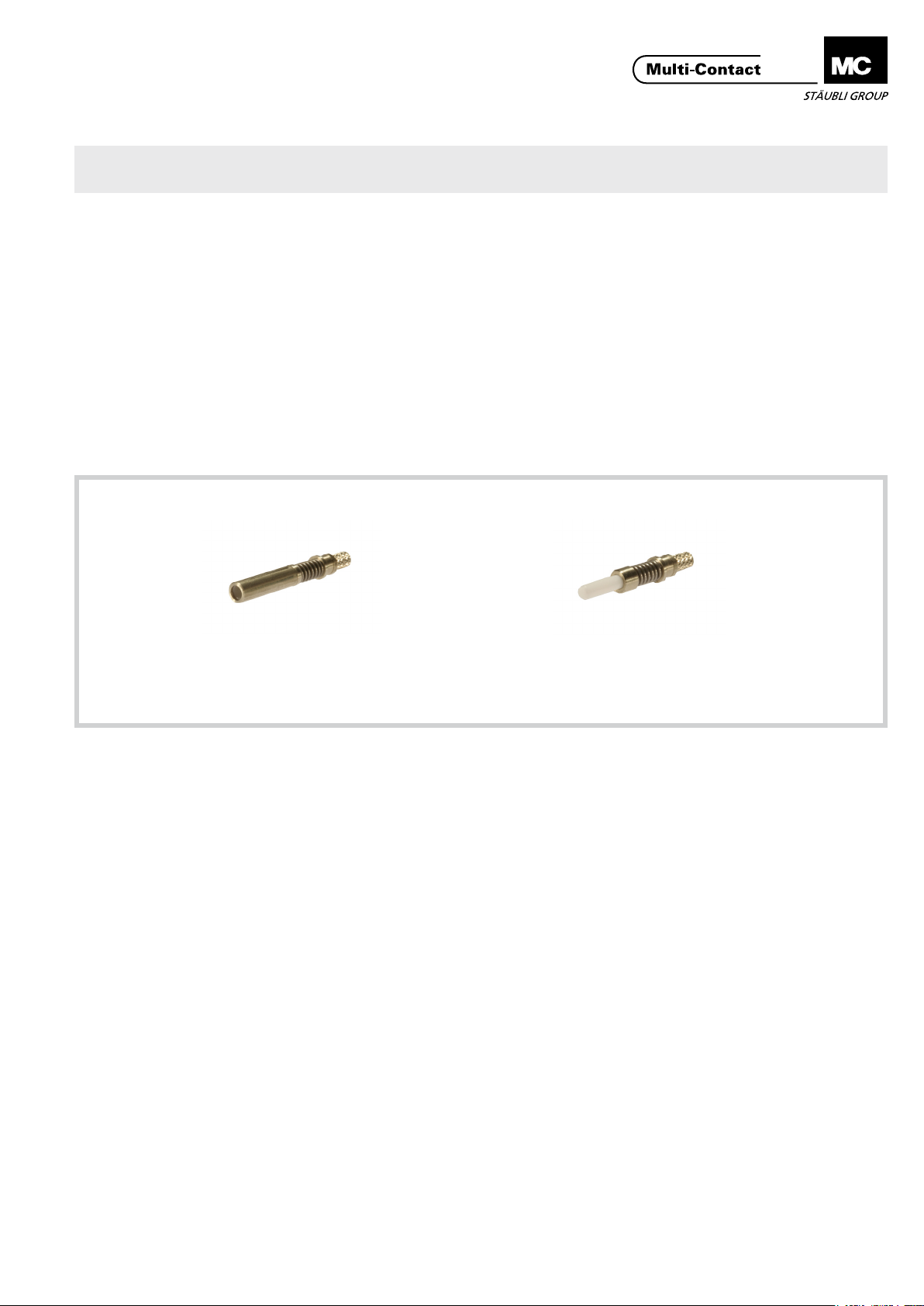
Contacto hembra
Socket contact
CT-B/GOF 33.0171
Los contactos broópticos GOF están optimizados para
su uso con cables broópticos de GI de 50/125μm o
62,5/125μm y con soportes aislantes de la serie CT-E4GOF.
Contacto macho
Pin contact
CT-S/GOF 33.0571
The GOF contacts are optimized for applications with
50/125μm or 62.5/125μm GI optical ber and insulators
in the CT-E-4GOF range.
www.multi-contact.com 1 / 8
Page 2
Advanced Contact Technology
Instrucciones de seguridad Safety instructions
Solo personal adecuadamente cualicado y especialistas formados podrán realizar el montaje y la instalación de los productos, teniendo en cuenta todas las regulaciones y normas
de seguridad legales aplicables�
Multi-Contact (MC) no se responsabiliza del incumplimiento
de estas advertencias�
Utilice solo los componentes y las herramientas indicados
por MC� No se desvíe de los procedimientos de preparación y
montaje aquí descritos� En caso de una manipulación inadecuada, no se podrá garantizar la seguridad ni la conformidad
con los datos técnicos. No modique el producto en ningún
caso�
Los conectores no fabricados por MC que se pueden conectar
con elementos MC, a veces denominados por los fabricantes
como "compatibles con MC", no cumplen con los requisitos
para una conexión eléctrica segura y estable a largo plazo, por
lo que, por motivos de seguridad, no pueden conectarse con
elementos MC� Por tanto, MC no se responsabilizará de los
daños causados por la conexión de conectores no autorizados
por MC con elementos MC�
Los trabajos aquí descritos no pueden llevarse a
cabo en piezas conectadas a la red o con tensión.
El producto nal (conectores congurados correctamente) debe proporcionar protección ante una
descarga eléctrica. El usuario mismo debe asegurar la protección.
Los conectores no pueden separarse estando cargados. Se permite la conexión y desconexión con
tensión.
Antes de cada uso debe comprobarse (particularmen-
te el aislante) de que no haya posibles defectos externos. En caso de duda sobre la seguridad, se debe
consultar a un especialista o el conector debe ser reemplazado.
Los conectores son impermeables según el tipo de
protección IP indicado para cada producto.
Los conectores no conectados deben protegerse ante
la humedad y suciedad. Los conectores ensuciados
no deben conectarse entre sí.
The products may be assembled and installed exclusively by
suitably qualied and trained specialists duly observing all applicable safety regulations�
Multi-Contact (MC) does not accept any liability in the event of
failure to observe these warnings�
Use only the components and tools specied by MC. In case
of self-assembly, do not deviate from the preparation and assembly instructions as stated herein, otherwise MC cannot
give any guarantee as to safety or conformity with the technical data� Do not modify the product in any way�
Connectors not originally manufactured by MC which can
be mated with MC elements and in some cases are even
described as ”MC-compatible” by certain manufacturers do
not conform to the requirements for safe electrical connection with long-term stability, and for safety reasons must not
be plugged together with MC elements� MC therefore does
not accept any liability for any damages resulting from mating
such connectors (i�e� lacking MC approval) with MC elements�
The work described here must not be carried out
on live or load-carrying parts.
Protection from electric shock must be assured by
the end product (i.e. by the correctly assembled
plug connector) and by its user.
The plug connections must not be disconnected
under load. Plugging and unplugging when live is
permitted.
Each time the connector is used, it should previous-
ly be inspected for external defects (particularly the
insulation). If there are any doubts as to its safety, a
specialist must be consulted or the connector must
be replaced.
The plug connectors are watertight in accordance
with the product specic IP protection class.
Unmated plug connectors must be protected from
moisture and dirt. The male and female parts must
not be plugged together when soiled.
Encontrará más detalles técnicos en el catálogo del
producto.
For further technical data please see the product cat-
alogue.
Explicación de los símbolos Explanation of the symbols
Advertencia de voltajes peligrosos
Advertencia de área de peligro Warning of a hazard area
Sugerencia o consejo útil Useful hint or tip
2 / 8 www.multi-contact.com
Warning of dangerous voltages
Page 3
Advanced Contact Technology
Herramientas necesarias Tools required
Para ensamblar los contactos y los ca-
bles de GI, se recomienda utilizar las
siguientes herramientas (disponibles a
petición)�
■
Crimpadora hexagonal,
910CZ00100002
■
Pelacables de 0,18mm,
910AB00118001
■
Pelacables de 0,3mm,
910AB00130001
■
Cuchilla para bra,
910FRW0100001
■
Adhesivo de 2 componentes,
9102KKFERTIG1
■
Jeringa desechable y cánula,
910SPRITZ0001
■
Papel de lija de 5µm,
910PB00105001
■
Papel de lija de 0,3µm,
910PB00100301
■
Horno de secado, 910AO00100001
■
Disco de pulir, 910PS0ST00001
■
Microscopio de 100x aumentos (sin
adaptador), 910MIKRO10002
■
Adaptador, 910MIADAST002
■
Cúter
■
Tijera para Kevlar
The following tools are recommended
for assembling the contacts with
GI-cables (available on request).
■
Hexagonal crimping pliers,
910CZ00100002
■
Insulation stripper 0.18mm,
910AB00118001
■
Insulation stripper 0.3mm,
910AB00130001
■
Fiber cleaving tool,
910FRW0100001
■
Two-component adhesive,
9102KKFERTIG1
■
One-way syringe with needle,
910SPRITZ0001
■
Polishing sheet 5µm,
910PB00105001
■
Polishing sheet 0.3µm,
910PB00100301
■
Heat oven, 910AO00100001
■
Polishing disc, 910PS0ST00001
■
100x microscope (without adapter),
910MIKRO10002
■
Adapter, 910MIADAST002
■
Cutter
■
Kevlar cutter
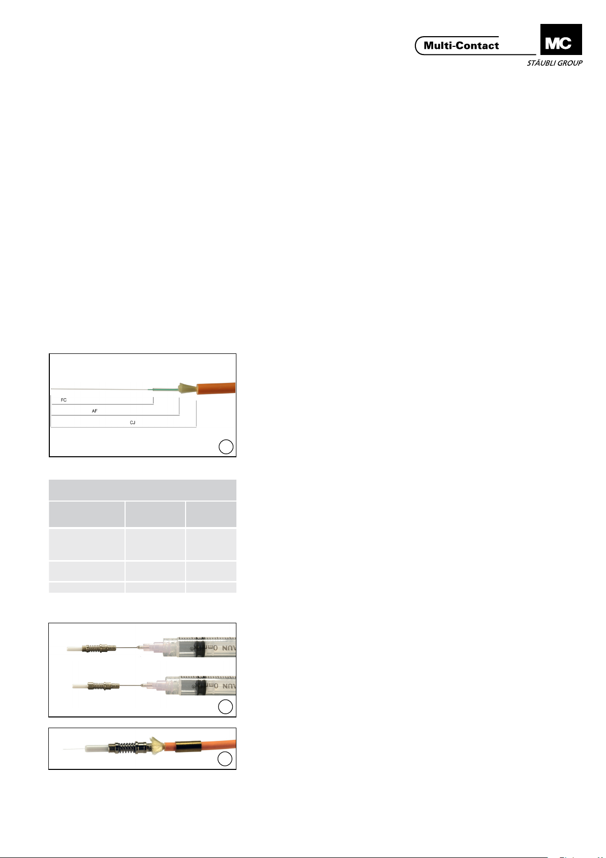
Tab. 1
Longitudes de pelado
Strip lengths
Descripción
Description
recubrimiento
CJ -
del cable
CJ - Cable cladding
AF - Kevlar Secon-
dary Coating
FC - Coating 30mm 30mm
Contacto
hembra
Socket contact
40mm 40mm
35mm 35mm
Contacto
macho
Pin contact
1
Pelado del cable Stripping the cable
(ill. 1)
Cortar el cable a medida�
Utilizar el cúter para retirar el recubrimiento del cable según las longitudes
indicadas en la tabla 1�
Recortar el lamento de descarga de
tracción con la tijera para Kevlar�
Retirar el tubo holgado y el revestimiento secundario con el pelacables
de 0,3mm.
Retirar el revestimiento primario con el
pelacables de 0,18mm.
Si quedara alguna impureza en la
bra, quitarla con un paño suave.
(ill. 1)
Cut the cable to length�
Remove the cable cladding using the
cutter according to the dimensions in
Table 1�
Use the Kevlar cutter to shorten the
strain relief cord�
Remove the buffer tube and the
secondary coating using the 0.3mm
insulation stripper�
Remove the primary coating using the
0.18mm insulation stripper.
Remove any residue on the ber using
a soft cloth (microber cloth).
Montaje del contacto Contact assembly
(ill. 2)
Preparar la cantidad necesaria de
adhesivo�
Llenar el contacto de adhesivo con la
jeringa desechable�
Colocar el manguito de crimpado
sobre el cable�
2
(ill. 3)
Introducir la bra en el contacto hasta
que haga tope. El extremo de la bra
debería sobresalir del casquillo unos
3
20mm.
(ill. 2)
Prepare an appropriate amount of
adhesive�
Fill the contact with adhesive using
the one-way syringe with needle�
Push the crimp sleeve onto the cable�
(ill. 3)
Insert the ber into the contact until it
stops. The end of the ber should project about 20mm out of the ferrule.
www.multi-contact.com 3 / 8
Page 4

Advanced Contact Technology
Tab. 2
Temperatura
Temperature
20°C 12h
80°C 45min
100°C 10min
120°C 5min
150°C 1min
Tiempo
Time
(ill. 4)
Colocar el manguito de crimpado por
encima del Kevlar y llevarlo hasta el
4
anclaje�
(ill. 5)
Introducir los contactos con el manguito de crimpado en la matriz de
3,3mm de la crimpadora.
Pretensar la crimpadora, alinear el
contacto y cerrar completamente la
mordaza hasta que se oiga cómo se
(ill. 4)
Push the crimp sleeve over the Kevlar
and onto the anchor�
(ill. 5)
Lay the contacts with the crimp sleeve
into the 3.3mm sunken opening on
the crimping pliers�
Pre-tension the crimping pliers, adjust
the contact and close the pliers completely until it unlocks audible�
desbloquea�
Secado del adhesivo Adhesive curing
Para aplicar el adhesivo mezclado, a
temperatura ambiente, se dispone
de un tiempo aprox� de 90 minutos�
Se puede variar el tiempo de secado
del adhesivo aplicándole temperatura
mediante una caja calentadora o un
5
armario térmico� Para un secado total,
el adhesivo requiere los tiempos indicados en la siguiente tabla (tabla 2)�
No se deben manipular los contactos
hasta que el adhesivo haya terminado
de secarse completamente�
Introducir con cuidado los contactos
crimpados en los oricios de la caja
calentadora para evitar una rotura
accidental de la bra.
The adhesive has a pot life of approximately 90 minutes at room temperature� The hardening time of the
adhesive can be reduced by increasing the temperature, using a heat box
or warming cabinet, for example� The
adhesive takes the times given in the
table below (Table 2) to harden completely� The contact should only be
processed further once the adhesive
has hardened completely�
In order to avoid breakage of the ber,
please insert the crimped contacts
very carefully into the openings of the
heat box
Rasgado y rotura Scratching and breaking
(ill. 6)
Una vez seco el adhesivo, extraer el
contacto de la caja calentadora y ras-
gar ligeramente la bra que sobresale
a una distancia de aprox� 1mm de la
cara frontal del casquillo con la cuchi-
lla para bra (1) y retirarla aplicando
una leve tracción axial (2)�
6
(ill. 6)
Once the adhesive has set, remove
the contact from the heat box� Gently
scratch the projecting ber at about
1mm from the ferrule-end surface
using the ber cleaving tool (1).
Remove the ber under slight axial
tension (2)�
4 / 8 www.multi-contact.com
Page 5

Advanced Contact Technology
Recticado de la bra Fiber grinding
(ill. 7)
Recticar a mano cuidadosamente
el extremo de la bra que sobresale
ejerciendo una ligera presión con el
papel de lija de 5μm.
(ill. 7)
Grind off manually and carefully the
protruding ber end with 5μm polishing sheet and with low pressure� Do
not use an underlayment�
No apoyar sobre ninguna supercie.
7
Pulido de la cara frontal Fiber endface polishing
(ill. 8 - 9)
Introducir el contacto en el disco de
pulir e ir puliéndolo con el papel de lija
de 0,3μm sobre una supercie dura
(p� ej�, una placa de vidrio)�
Comprobar la calidad de la supercie
del extremo de la bra con el micro-
scopio� Si hubiera rasguños en la zona
central de la bra, repetir el proceso
de pulido� Si quedasen impurezas tras
el proceso de pulido, estas pueden
retirarse con un paño suave (de micro-
bra).
Desenroscar el casquillo del contacto
hembra y proteger la supercie del
extremo de la bra de la suciedad con
un tapón guardapolvo�
(ill. 8 - 9)
Put the contact into the polishing disc
and polish the ber with the 0.3μm
polishing sheet on a hard base, for
example a glass plate�
Check the quality of the ber-end
surface with the microscope. If there
are scratches near the core of the
ber, repeat the polishing process.
Any residue produced by the polishing
process can be removed using a soft
cloth (microber cloth). Unscrew the
ferrule sleeve of the socket contact
and protect the ber-end surface from
dirt with a dust cover�
8
9
www.multi-contact.com 5 / 8
Page 6

Advanced Contact Technology
Notas / Notes:
6 / 8 www.multi-contact.com
Page 7

Advanced Contact Technology
Notas / Notes:
www.multi-contact.com 7 / 8
Page 8
Advanced Contact Technology
Notas / Notes:
Fabricante/Producer:
Multi-Contact AG
Stockbrunnenrain 8
CH – 4123 Allschwil
Tel. +41/61/306 55 55
Fax +41/61/306 55 56
mail basel@multi-contact.com
www.multi-contact.com
© by Multi-Contact AG, Switzerland – MA092 – 05.2014, Index a, Global Communications – Sujeto a modicaciones / Subject to alterations
 Loading...