

Page 1
Advanced Contact Technology
MA000 (de_en)
MA065 (es_en)
Montageanleitung
Instrucciones de montaje
Pinza a crimpare per terminale
a bre ottiche CT-CZ/LWL
Índice
Instrucciones de seguridad ........................................................2
Ajustes ���������������������������������������������������������������������������������������3
Engarze ��������������������������������������������������������������������������������������3
Vericación del tamaño del engarce �����������������������������������������4
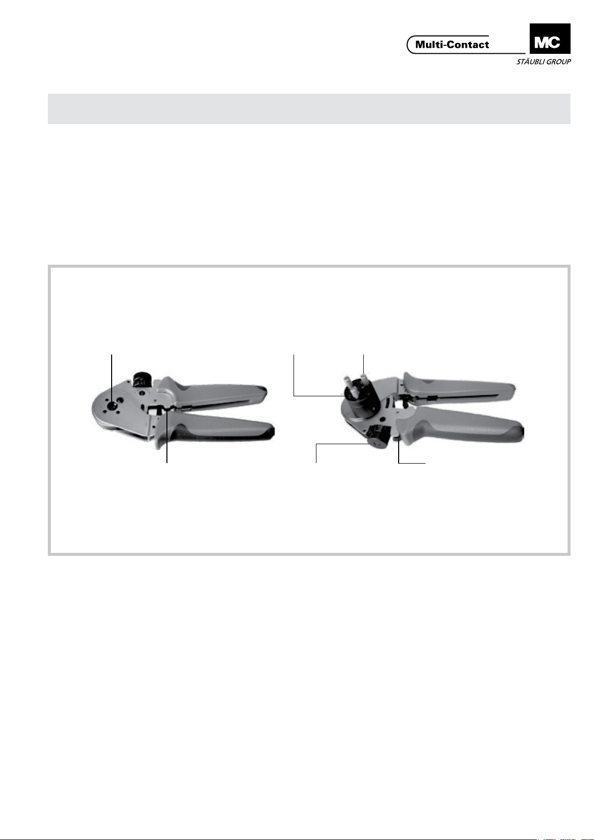
Parte frontal
Front side
Oricio de engarzado
Crimping opening
Posicionador
Locator
MA000 (de_en)
MA065 (es_en)
Assembly instructions
Assembly instructions
Crimping pliers for plastic optical bre CT-CZ/LWL
Content
Safety Instructions ......................................................................2
Settings �������������������������������������������������������������������������������������3
Crimping ������������������������������������������������������������������������������������3
Check the crimp size �����������������������������������������������������������������4
Parte posterior
Back side
Perno de posicionamiento
Positioning pin
Tope
Limit stop
Rueda para ajustar la profundidad de
los mandriles de engarce
Knob for adjusting
the depth of the crimp mandrels
Abertura para accionar la
palanca de desbloqueo
Opening for actuating the
jamming release lever
www.multi-contact.com 1 / 4
Page 2
Advanced Contact Technology
Advanced Contact Technology
Instrucciones de seguridad Safety instructions
Sólo personal adecuadamente cualicado y especialistas formados podran realizar el montaje y la instalación de los productos teniendo en cuenta todas las regulaciones de seguridad aplicables.
Multi-Contact (MC) no se responsabiliza ante el incumplimiento de estas advertencias.
Utilice sólo los componentes y herrmientas indicadas por MC.
No se desvíe de los procedimientos de preparación y montaje
aquí descritos, en caso de una manipulación inadecuada no
se podrá garantizar la seguridad ni la conformidad con los datos técnicos. No modique el prodcuto en ningún caso.
Los conectores no fabricados por MC que se pueden conectar
con elementos MC, a veces denominados por los fabricantes
como „compatibles con MC“ no cumplen con los requisitos
para una conexión eléctrica segura y estable a largo plazo.
No pueden conectarse con elementos MC por motivos de seguridad. Por tanto, MC no se responsabilizará de los daños
surgidos por la conexión de conectores no autorizados por
MC con elementos MC.
Los trabajos aquí descritos no pueden ejecutarse
en piezas conectadas a la red y con tensión.
El producto nal debe proporcionar protección al
usuario frente a una descarga eléctrica.
Los conectores no pueden separarse estando cargados. Se permite la conexión y desconexión con
tensión.
Cada vez que el conector sea usado, éste debe ser
inspeccionado previamente por posibles defectos
externos (particularmente en el aislante). Si hay
alguna duda para su seguridad, se debe consultar a
un especialista o el conector debe ser reemplazado.
Los conectores son impermeables según el tipo de
protección IP.
Se deben proteger ante la humedad y suciedad los
conectores no conectados. No se pueden conectar
conectores sucios.
Encontrará más detalles técnicos en el catálogo del
producto.
The products may be assembled and installed exclusively by
suitably qualied and trained specialists duly observing all applicable safety regulations.
Multi-Contact (MC) does not accept any liability in the event of
failure to observe these warnings.
Use only the components and tools specied by MC. In case
of self-assembly, do not deviate from the preparation and assembly instructions as stated herein, otherwise MC cannot
give any guarantee as to safety or conformity with the technical data. Do not modify the product in any way.
Connectors not originally manufactured by MC which can
be mated with MC elements and in some cases are even
described as ”MC-compatible” by certain manufacturers do
not conform to the requirements for safe electrical connection with long-term stability, and for safety reasons must not
be plugged together with MC elements. MC therefore does
not accept any liability for any damages resulting from mating
such connectors (i.e. lacking MC approval) with MC elements.
The work described here must not be carried out
on live or load-carrying parts.
Protection from electric shock must be assured by
the end product (i.e. by the correctly assembled
plug connector) and by its user.
The plug connections must not be disconnected
under load. Plugging and unplugging when live is
permitted.
Each time the connector is used, it should previously
be inspected for external defects (particularly in the
insulation). If there are any doubts as to its safety, a
specialist must be consulted or the connector must
be replaced.
The plug connectors are watertight in accordance
with the product specic IP protection class.
Unmated plug connectors must be protected from
moisture and dirt. The male and female parts must
not be plugged together when soiled.
For further technical data please see the product
catalogue.
Ajustes Settings
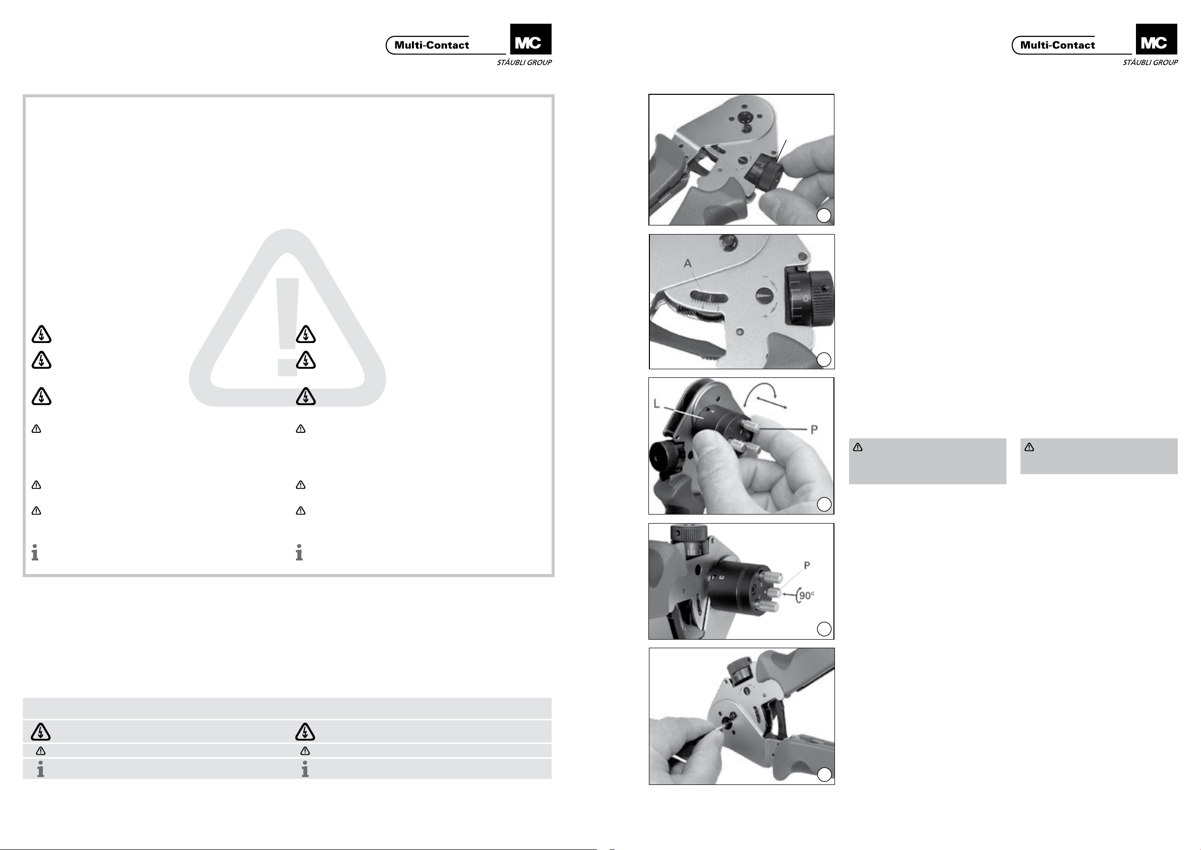
(ill. 1)
S
Fije la profundidad del engarce girando la rueda (S). Para el macho CT-S/
LWL y la toma CT-B/LWL, la profundidad del engarce se ja en 1,45mm.
1
(ill. 2)
Cada división de la escala (A) corresponde a 0,2mm. Cada giro de la
rueda (S) corresponde a 0,2mm.
2
(ill. 3)
Tire del posicionador (L) y gire hasta la
posición deseada. Para la toma
CT-B/LWL, la pos. 2, para el macho
CT-S/LWL, la pos.1.
Atención
Los pernos de posicionamiento
(P) no deben estar introducidos ni
bloqueados.
3
(ill. 4)
Introduzac el perno de posicionamiento (P) en el posicionador y bloquéelo
girando 90°.
(ill. 1)
Set the crimping depth by turning the
knob (S). For the pin CT-S/LWL and
the socket CT-B/LWL, the crimping
depth is set at 1,45mm.
(ill. 2)
Each division on the scale (A) corresponds to 0,2mm. One turn of the
knob (S) corresponds to 0,2mm.
(ill. 3)
Pull out the locator (L) and turn to the
desired position. For socket CT-B/LWL
Pos. 2, for pin CT-S/LWL in Pos.1.
Attention
The positioning pins (P) may not
be pushed in and locked.
(ill. 4)
Push in positioning pin (P) on the locator and lock by turning through 90°.
Explicación de los símbolos Explanation of the symbols
Advertencia de voltajes peligrosos
Advertencia de área de peligro Warning of a hazard area
Sugerencia o consejo útil Useful hint or tip
2 / 4 www.multi-contact.com
Warning of dangerous voltages
4
Engarze Crimping
(ill. 5)
Inserte el contacto de bra óptica en
el oricio de engarce y cierre las tenazas hasta el primer tope. Introduzca al
máximo el cable y el contacto contra
el tope y cierre las tenazas completamente. Las tenazas deben abrirse al
soltar. Esto garantiza que el engarce
se ha realizado correctamente.
5
www.multi-contact.com 3 / 4
(ill. 5)
Insert optical bre contact in the
crimping opening and close the pliers
to the rst engagement point. Insert
the prepared cable into the optical
bre contact as far as it will go, gently
press cable and contact against the
stop and close the pliers completely.
The pliers must open when released.
This ensures that the crimping operation has been correctly carried out.
Page 3

Advanced Contact Technology
(ill. 6)
Retire el contacto para bra óptica engarzado. Antes de cambiar la posición
del posicionador, desbloquee el perno
de posicionamiento (P)�
(ill. 6)
Remove the crimped optical bre
contact from the pliers. If a new locator position is selected, the positioning pin (P) must be unlocked before
repositioning.
6
Vericación del tamaño del
Check the crimp size
engarce
(ill. 7)
El tamaño del engarce debe vericarse periódicamente. Para ello se
precisa un calibre cilíndrico liso de
Ø 1mm (D) que se suministra con
las tenazas. Fije la rueda (S) en 1mm
(pos. 0) y cierre las tenazas. En esta
D
posición es posible mover el calibre
entre los mandriles de engarce sin juego. Si no es el caso, la desviación puede determinarse con un ajuste preciso
de la rueda de ajuste. Si la desviación
es mayor o menor a 0,06mm, contacte el suministrator de las tenazas.
(ill. 7)
The crimp size should be occasionally checked. This requires a Ø 1mm
gauge pin (D) which is supplied with
the pliers. The size 1mm (pos. 0) is
set on the knob (S) and the pliers are
closed. In this position it must be possible to move the gauge pin between
the crimp mandrels without play. If
this is not the case, the size deviation can be determined by the ne
adjustment of the setting knob. If the
deviation is plus or minus 0,06mm,
the supplier of the pliers must be
contacted.
1 0
Fabricante/Producer:
Multi-Contact AG
Stockbrunnenrain 8
CH – 4123 Allschwil
Tel. +41/61/306 55 55
Fax +41/61/306 55 56
mail basel@multi-contact.com
www.multi-contact.com
7
© by Multi-Contact AG, Switzerland – MA065 – 10.2013, Index b, Global Communications – Sujeto a modicaciones / Subject to alterations
 Loading...