

Multiaqua MHCCW Installation Manual
Rev. 1.2
MHCCW (115)
INSTALLATION & OPERATING
MANUAL
MHCCW Fan Coils 1- 3 Tons
ENCLOSURE
FAN
COIL
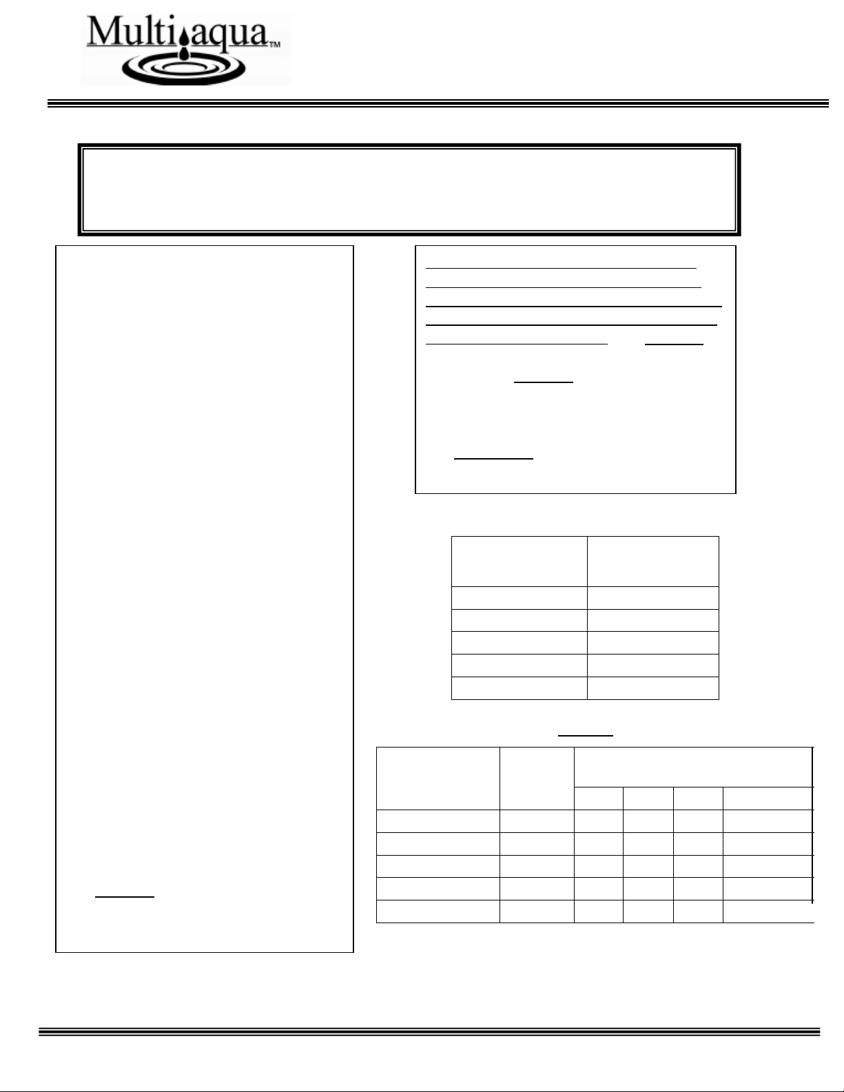
ENCLOSURE DIMENSIONS (in.)
PART NUMBER
SIZE
Depth
Length
Height
Weight (LBS.)
MPE468
4
32.75
39.75
11.00
26
MPE468
6
32.75
39.75
11.00
26
MPE468
8
32.75
39.75
11.00
26
MPE10
10
32.75
45.75
11.00
30
MPE12
12
32.75
51.75
11.00
34
Figure 2
GENERAL
Read the entire contents of this manual
before beginning installation. Multiaqua
assumes no responsibility for equipment
installed contradictory to any code
requirement or installation instructions.
The components of this fan coil have
been inspected at the factory and readied
for shipment. Upon receiving the
shipment a visual inspection of the
packaging must be performed.
If any damage to the packaging is
discovered, an inspection of the
components must be performed and
noted on the delivery documents. If
component damage is found a damage
claim must be filed by the receiving party
against the delivery party immediately.
This product is designed and
manufactured to permit installation in
accordance with national codes. It is the
installer’s responsibility to install the
product in accordance with national
codes and/or prevailing local codes and
regulations.
Care must be taken to ensure the
structural integrity of the supporting
members, clearances and provisions for
servicing, power supply, coil connections
and/or condensate removal. Before the
installation ensure the structural strength
of the supporting members is sufficient.
See Figure 1 for hanging weights of the
fan coils.
-------------------------------------- CAUTION --------------------------------------
Care must be taken when handling sheet metal. Sheet metal parts have sharp edges and could
cause injury.
This unit is designed to be installed in an
horizontal configuration only, and into an
enclosure assembly. The enclosure assembly
can be ordered separately or field fabricated
by the installing contractor. See Figure 2
for enclosure part numbers, dimensions and
weights. See Figure 3 for fan coil only
dimensions.
The coil hand of connection is field
reversible to left or right hand connection.
See Figures 4-6 for converting the coil hand
of connection.
FAN COIL
APPROXIMATED
MODEL NUMBER
WEIGHTS (LBS)
MHCCW-04
66.0
MHCCW-06
68.2
MHCCW-08
72.6
MHCCW-10
74.8
MHCCW-12
83.6
Figure 1
2
INSTALLATION & OPERATING
MANUAL
MHCCW Fan Coils 1- 3 Tons
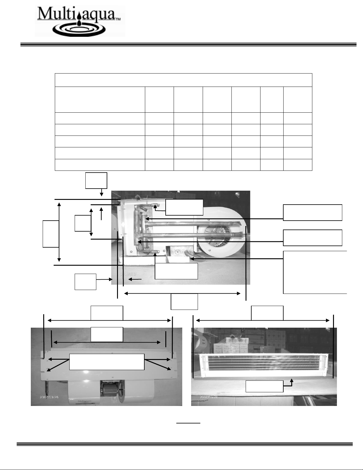
FAN COIL DIMENSIONS
Fan Coil
A B C D E
F
Model Number
MHCCW04-XX
37.72
34.56
31.41
10.23
5.51
21.65
MHCCW06-XX
37.72
34.56
31.41
10.23
5.51
21.65
MHCCW08-XX
37.72
34.56
31.41
10.23
5.51
21.65
MHCCW10-XX
43.70
40.55
37.40
10.23
5.51
21.65
MHCCW12-XX
49.68
46.53
43.38
10.23
5.51
21.65
F
E
D
Water Return
Water Supply
1”
.75” (MPT)
Condensate
Drain Connection
(Both Ends)
.5”
Air Vent
Coil Drain
B
C
A
Drain Pan
Mounting Notches
Figure 3
Figure 3
3
INSTALLATION & OPERATING
MANUAL
MHCCW Fan Coils 1- 3 Tons
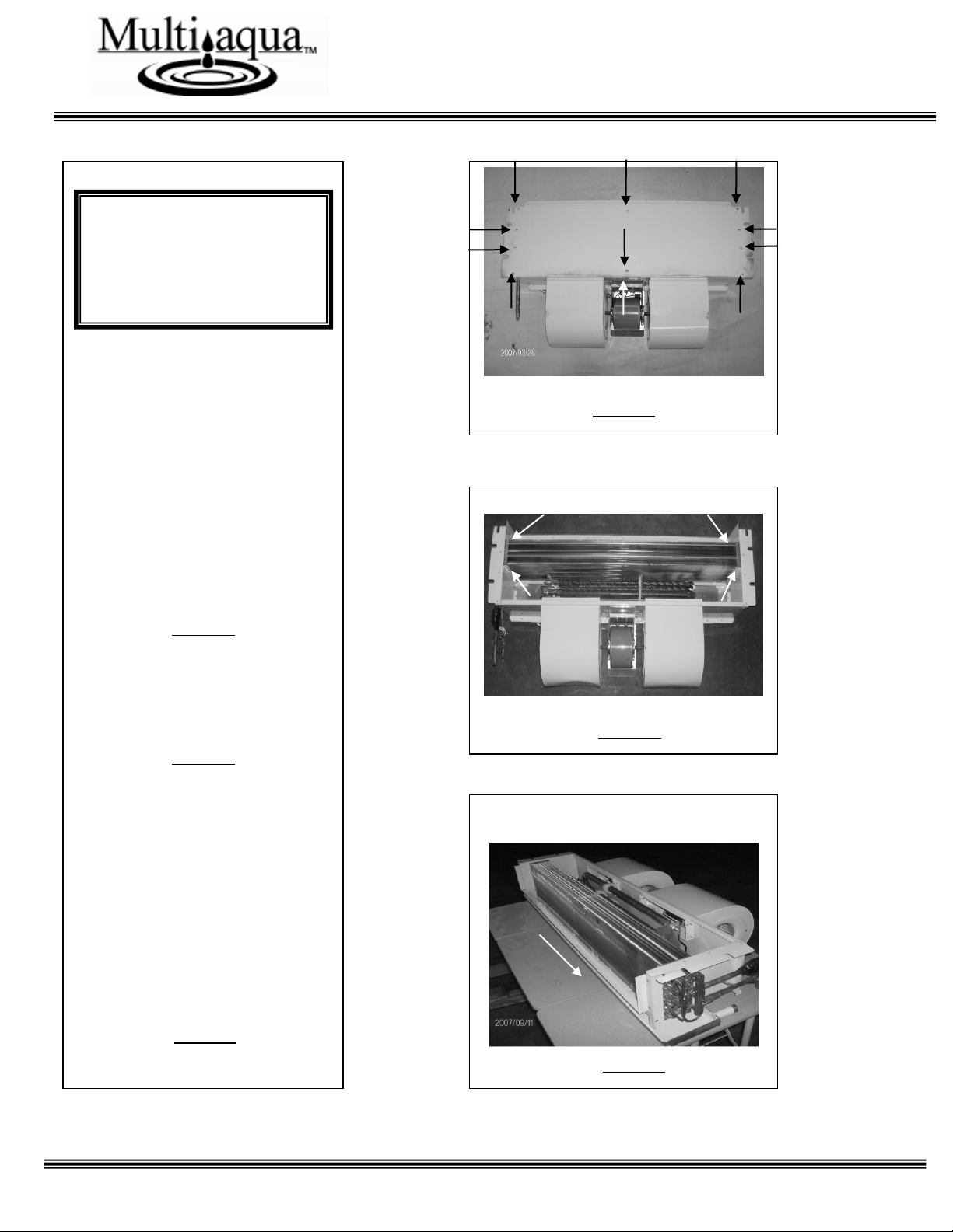
Figure 4
INSTRUCTIONS FOR
CONVERTING COIL HAND
CONNECTION (Left or Right)
& ELECTRIC HEATER
ACCESS.
1. Remove the eleven screws that
attach the top to the fan coil
assembly and remove the top.
This will allow you to access the
electric heaters.
Figure 4
2. Remove the eight screws that
hold the coil into the fan coil
frame assembly. Four screws per
side.
Figure 5
3 Slide the coil out of the fan
coil frame assembly toward the
coil supply and return line
connections. Ensure that care is
taken when removing and
inserting the coil not to damage
the coil fins. Insert the coil into
the fan coil frame assembly from
the other end and reverse
procedures 4 & 5 to reassemble
the fan coil.
Figure 6
Figure 5
Figure 6
-------- CAUTION -------
Care must be taken when
handling sheet metal. Sheet
metal parts have sharp edges
and could cause injury.
4
 Loading...