

Page 1
Rev. 1.1
Page 2
INSTALLATION & OPERATING
MANUAL
MCCX Fan Coils 4 & 5 Tons
GENERAL
Read the entire contents of this manual
before beginning installation. Multiaqua
assumes no responsibility for equipment
installed contradictory to any code
requirement or installation instructions.
The components of this fan coil have
been inspected at the factory and readied
for shipment. Upon receiving the
shipment a visual inspection of the
packaging must be performed.
If any damage to the packaging is
discovered, an inspection of the
components must be performed and
noted on the delivery documents. If
component damage is found, a damage
claim must be filed by the receiving party
against the delivery party immediately.
This product is designed and
manufactured to permit installation in
accordance with national codes. It is the
installer’s responsibility to install the
product in accordance with national
codes and/or prevailing local codes and
regulations.
Care must be taken to ensure the
structural integrity of the supporting
members, clearances and provisions for
servicing, power supply, coil connections
and/or condensate removal. Before the
installation, ensure the structural strength
of the supporting members is sufficient.
See Figure 1 for hanging weights of the
fan coils.
This unit is designed to be installed in a
-------------------------------------- CAUTION --------------------------------------
Care must be taken when handling sheet metal. Sheet metal parts have sharp edges and could
cause injury.
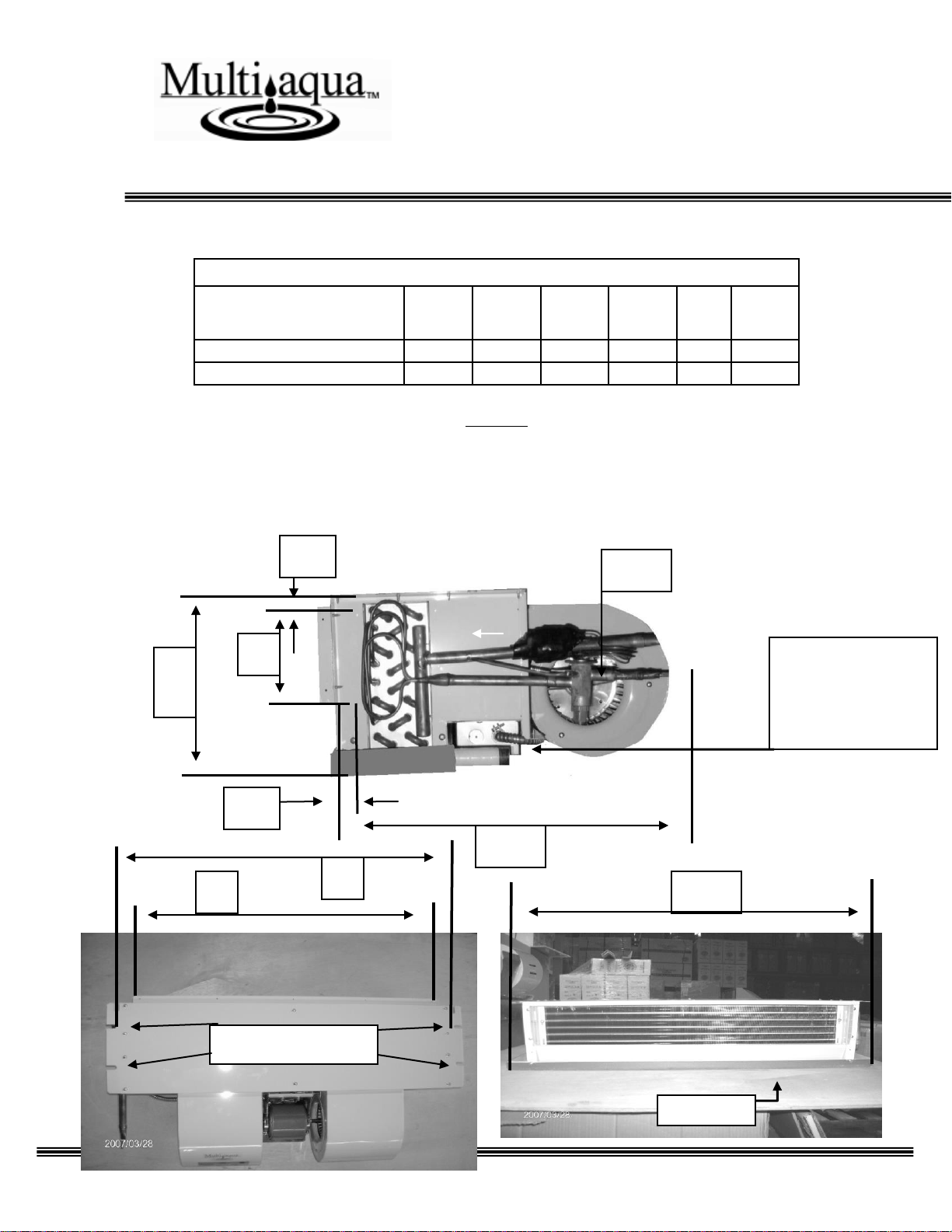
horizontal configuration only. See Figure 2
for fan coil dimensions.
FAN COIL
APPROXIMATED
MODEL NUMBER
WEIGHTS (LBS.)
MCCX-16-C-1
68.34
MCCX-20-C-1
72.80
Figure 1
2
Page 3
INSTALLATION & OPERATING
MANUAL
MCCX Fan Coils 4 & 5 Tons
FAN COIL DIMENSIONS (in)
Fan Coil
A B C D E
F
Model Number
MCCX-16-C-1
48.39
43.86
42.20
13.74
9.49
19.80
MCCX-20-C-1
56.38
51.85
42.20
13.74
9.49
19.80
Figure 2
F
E
D
1”
.75” (MPT)
Condensate
Drain Connection
(Both Ends)
.5”
TXV
Drain Pan
C
B
Mounting Notches
3
Page 4
INSTALLATION & OPERATING
MANUAL
MCCX Fan Coils 4 & 5 Tons
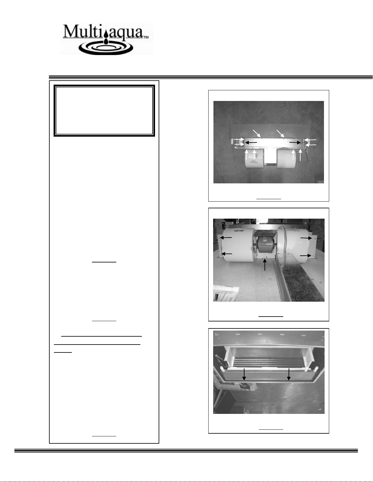
Figure 3
INSTRUCTIONS FOR
INSTALLING FAN COIL
UNIT INTO A FIELD
SUPPLIED ENCLOSURE
ASSEMBLY
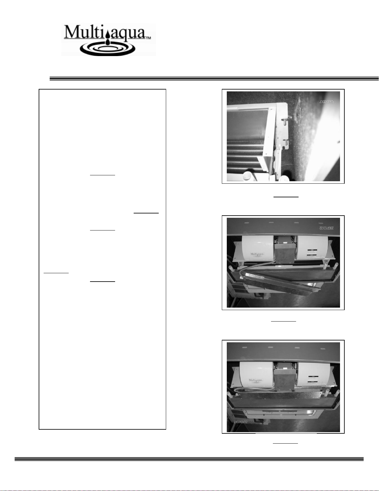
1. Remove the ten screws that
attach the electrical assembly to
the fan coil unit. Do not separate
the electrical assembly from the
blower assembly. These two
assemblies will be removed in the
next step.
Figure 3
2. Remove the five screws
attaching the blower assembly to
the coil assembly. Separate the
electrical and blower assemblies
from the coil assembly.
Figure 4
3. Enclosure assembly must be
field fabricated or supplied by
others. Insert the coil assembly
into the enclosure assembly
starting with the discharge air
opening of the coil first. Ensure
that the discharge of the coil is
inserted into the discharge of the
enclosure completely. Failure to
completely insert the coil
discharge will result in
recirculation of the discharge air.
Figure 5
Figure 4
Figure 5
-------- CAUTION -------
Care must be taken when
handling sheet metal. Sheet
metal parts have sharp edges
and could cause injury.
4
Page 5
INSTALLATION & OPERATING
MANUAL
MCCX Fan Coils 4 & 5 Tons
4. Use factory provided mounting
notches to hang the fan coil inside an
enclosure assembly.
Secure the coil assembly to the
enclosure with two mounting bolts per
side. Ensure that the coil assembly is
level in both directions to allow proper
drainage and operation.
Figure 6
5. Reinstall the blower assembly onto
the coil assembly using the five screws
previously removed in step 2, Figure 4.
Figure 7
6. Reinstall the electrical assembly
onto the coil assembly using the ten
screws previously removed in step 1,
Figure 3.
Figure 8
Figure 6
Figure 7
Figure 8
5
Page 6
INSTALLATION & OPERATING
MANUAL
MCCX Fan Coils 4 & 5 Tons
Figure 14
ELECTRICAL &
CONDENSATE DRAIN
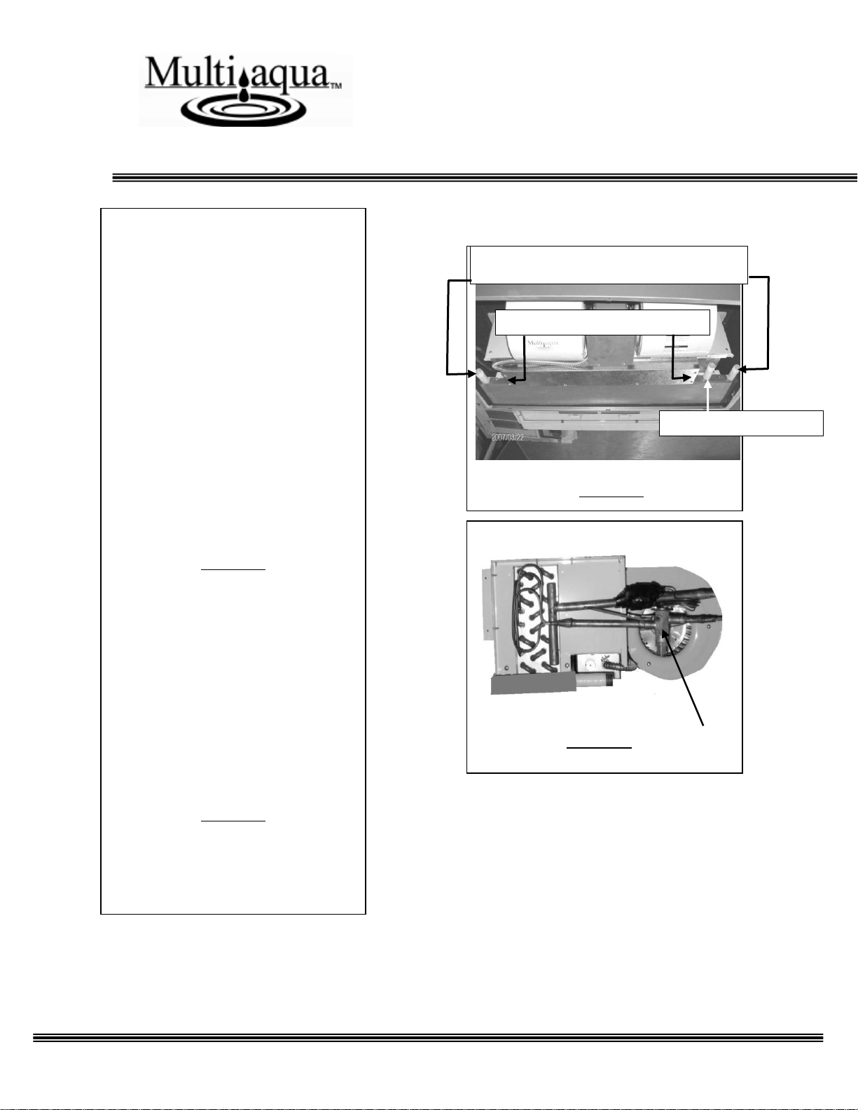
7. There are four termination
points for the electrical wiring.
There are two on each side of the
electrical box. See unit Wiring
Diagram for electrical drawings.
Wiring must be installed according
to prevailing codes and regulations.
The fan coil includes a condensate
drain connection.
Ensure that all condensate drain
lines have at least 1/4” of an inch of
fall per foot for proper drainage.
Figure 10
DIRECT EXPANSION COIL
CONNECTIONS
8. The fan coil unit comes with a
Thermal Expansion Valve (TXV)
installed on the DX coil. Ensure
that the suction line is insulated all
the way to the coil header and the
liquid line is insulated from the
TXV to the distributor.
Figure 11
Electrical Terminations Points
Safety Drain Connection
Left and Right Hand Drain Connections
Figure 11
Figure 10
6
Page 7
INSTALLATION & OPERATING
MANUAL
MCCX Fan Coils 4 & 5 Tons
MAITENANCE
1. Air Filter(s):
Filters are an essential part of the
quality of air that is provided to the
occupants. Never operate HVAC
equipment without filters. Filters
help remove dust and unwanted
particles from the air stream,
helping to keep the space clean.
They also keep this debris from
collecting on the heat transfer
surfaces of the unit thus
maintaining optimum equipment
efficiency and performance. These
filters will be located either in the
unit or upstream from the unit in
the return air ductwork. Filters must
be inspected, cleaned and/or
changed routinely. This routine
maintenance procedure will allow
the unit to continually operate as
designed, reduce service expenses
and extend equipment/component
life.
2. Fuses and/or Circuit Breakers:
This unit must be connected to
the buildings electric service in
accordance with local/national
electrical codes and regulations.
These electrical connections will
include over current protection in
the form of fuses or circuit
breakers. Have your contractor
identify/label the circuits and the
location of them so that you may be
in a position to make inspections
and/or replacements in the event the
unit fails to operate or is being
serviced. If fuses are used, ensure
that the replacement fuses are of the
same size and type as the ones you
are replacing. It is a good idea to
keep replacement fuses of the
appropriate size and type on hand.
3. Routine Check Up and Service:
This product is designed to
provide many years of dependable,
trouble free comfort when properly
maintained. Proper maintenance
will consist of routine filter
cleanings/changes, bi-annual checkups that include but not limited to
filter inspections, electric heater
inspections /cleaning of the internal
electrical and heat transfer
components by a qualified service
technician. Failure to provide
periodic check-ups and cleaning
can result in excessive operating
cost and/or equipment failure.
7
 Loading...