

Multiaqua MAC-036HE, MAC-048HE, MAC-060HE Installation And Operation Manual
Rev. 1.1

Table of Contents
Page
Introduction 3
System Description 4
Electrical & Physical Data 5-6
Description of Electrical Controls 7-8
Chiller Controls Sequence of Operation 9
System Faults 10
Refrigeration System Operation 10
Description of Refrigerant Components 11
Description of Piping Components 12
Layout & Design 13
Banked Chiller Configuration 14
Installation Notes 15-16
Propylene Glycol Mixture Chart 16
Expansion Tanks 16-17
System Filling Instructions 17
Air Elimination 18
Wiring Diagrams 19-24
Product Specifications 25
Page 2 of 28
Multiaqua Chiller Manual
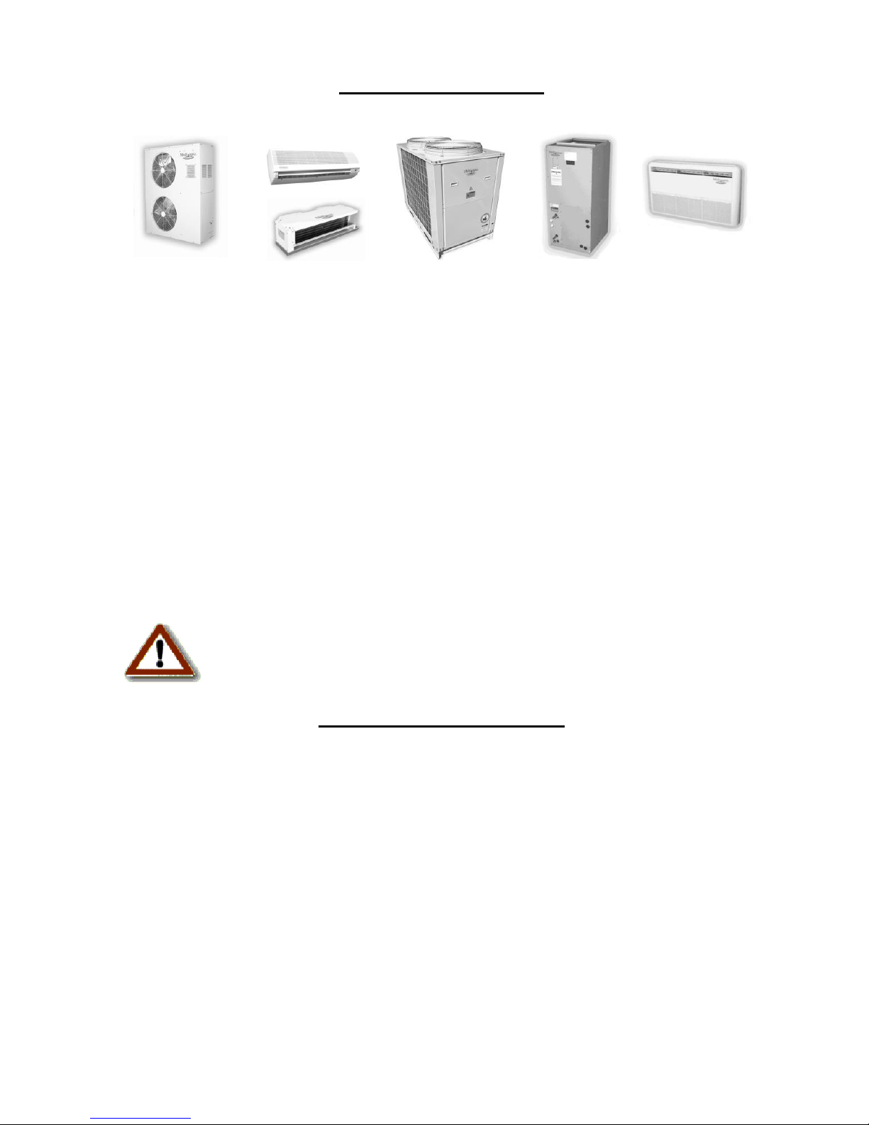
The Multiaqua Chiller System is the only air conditioning/refrigeration system of its kind in
the world today offering the degree of application flexibility described in the following
manual.
The Multiaqua Chiller System is not only unique in its application flexibility; it is unique in
superior quality, rated capacities, and rugged durability. When installed in accordance with
these instructions, the system will deliver years of trouble free service.
Proper equipment sizing, piping design, and installation are critical to the performance of the
chiller. This manual is meant to be a “how to” introduction to piping and installing the
Multiaqua Chiller System.
MAC-060HEChiller Features
Copeland Scroll Compressors
Loss of Flow Protection
Control Power Transformer
Low Ambient Option
Integrated Chilled Solution Pump Control
Flow Switch
Strainer Connection Kit
Painted Metal Condenser Protector Grille
Dual Refrigeration Circuits and Single Liquid Solution Circuit
RECOGNIZE THIS SYMBOL AS AN INDICATION OF IMPORTANT
SAFETY OR INSTRUCTION RELATED INFORMATION.
Website information addresses are supplied throughout this manual for piping and accessory
information. The plumbing industry also has pressure drop information on ferrous and copper
piping systems.
The following sections will describe each component and how it functions within the system.
Installation information is supplied where appropriate. The piping design section will explain
the design and layout the piping system from a “how to” perspective. Following the examples
provided will enable the installer to determine the correct pipe and accessory sizing, as well as
equipment location. It is important to know before installation if the proposed system will
operate correctly. That determination can be made by doing a formal layout of a new
application or a review of an existing piping system.
The chiller circulates a solution of water and Propylene Glycol. Throughout this manual the
term “liquid solution” is used in place of a water and glycol mixture.
It is essential to operate the system with a minimum of 10% glycol, or
more, as required by your climate zone. DO NOT OPERATE THIS
SYSTEM USING WATER ALONE.
For proper liquid solutions mix ratios, refer to page 16 or the glycol
manufacturer’s recommended mix ratios.
Page 3 of 28
System Description
The Multiaqua Chiller is a self-contained, air-cooled condenser, coupled with an insulated,
brazed plate heat exchanger (evaporator). The system utilizes scroll compressors to circulate
refrigerant between the condenser and heat exchanger. The refrigerant is metered into the heat
exchanger with a thermostatic expansion valve. Protecting the system are high and low
pressure switches as well as a liquid solution flow switch.
Liquid solution (water and Propylene Glycol) is circulated through the heat exchanger by the
chillers integral pump. The liquid solution flows through the heat exchanger to the system's
supply piping and on into the air handlers.
A solenoid-operated, motorized valve (or circulator) controls the flow of the chilled liquid
solution through the air handlers. The valves, or circulators, can be actuated by a variety of
different control schemes.
Liquid solution temperature is controlled by a chiller-mounted digital electronic control. A
system sequence of operation, individual control description, troubleshooting information,
and a schematic are included in the controls section.
It must be recognized that ferrous pipe may cause accelerated
deterioration of the brazed plate heat exchanger and could void the heat
exchanger warranty.
Cooling Load Diversity
Equipment sizing for a chilled liquid solution system can utilize Cooling Load Diversity.
Diversity is described as the actual amount of cooling needed (heat load) by various sections
of a structure at a given time. Conventional air conditioning systems are designed for the
highest structure heat load. The conventional system determines and selects equipment based
on the peak heat load demanded by the structure. A system sized to take advantage of
diversity would determine the heat load by the time of day, building exposure, and usage. As
an example, the sections of a structure facing west demand more cooling in the afternoon than
sections facing east. The opposite of this is true in the morning where the east section is
exposed to a higher heat load requiring more cooling. Utilizing diversity, the chiller system
would adapt to the needs of each side of the structure during peak demand by delivering more
cooling to that area and less to the areas that do not need it. A structure utilizing a
conventional DX system that requires 8 tons of cooling at peak load could utilize a much
smaller capacity system (potentially 4 or 5 tons) if the system installed could take advantage
of load diversity. Load diversity would supply the necessary amount of cooling to the space
when or as needed instead of keeping a total larger capacity available at all times.
Page 4 of 28
Cooling Load Diversity
Continued
Cooling load diversity can best be determined by referring to the ACCA (Air Conditioning
Contractors of America) Manual “J”. Refer to the appendix A-2:Multi-Zone Systems.
ACCA’s Internet address is http://www.acca.org/
Due to load diversity, a Multiaqua Chiller can serve more total air handler tonnage than the
actual total chiller capacity. For example, a 10 ton chiller may be delivering chilled liquid
solution to 13 tons or more of air handler capacity. Thus, with cooling load diversity in use,
the building does not need equal amounts of cooling in each area at the same time.
Electrical and Physical Data
The information contained in this manual has been prepared to assist in the proper installation,
operation, and maintenance of the chiller. Improper installation or installation not made in
accordance with these instructions can result in unsatisfactory operation and/or dangerous
conditions which can void the related warranty.
Read this manual and any instructions included with all additional equipment that is required
to make up the system prior to installation. Retain this manual for future reference.
Separate and independent power supplies and disconnects must be
provided.
All power to the chiller must be turned off prior to opening cabinet and/or
servicing.
Failure to properly ground chiller can result in death.
Disconnect all power wiring to chiller before any maintenance or service
work. Failure to do so can cause electrical shock resulting in personal
injury or death.
All wiring must be done in accordance with NEC (National Electric Code),
as well as state and local codes, by qualified electricians.
Product warranty does not cover any damages or defect to the chiller
caused by the attachment or use of any components, accessories, or devices
(other than those authorized by the manufacturer) into, onto, or in
conjunction with the chiller. You should be aware that the use of
unauthorized components, accessories, or devices may adversely affect the
operation of the chiller and may also endanger life and property. The
manufacturer disclaims any responsibility for such loss or injury resulting
from the use of unauthorized components, accessories, or devices.
Page 5 of 28
Electrical and Physical Data
(Continued)
Upon receiving the chiller and components, inspect for any shipping
damage. Claims for damage, either apparent or concealed, should be filed
immediately with the shipping company.
No liquid, other than the liquid solution mixture of water and Propylene
Glycol, shall be used in the piping system and must be mixed in
accordance with table 6 on page 16.
Corrosive environments may subject metal parts of the chiller to rust and
deterioration. The oxidation could shorten the chiller’s useful life.
Corrosive elements include salt spray, fog or mist in sea coastal areas,
sulfur or chlorine from lawn watering systems, and various chemical
contaminants from industries such as paper mills and petroleum
refineries.
If the unit is to be installed in an area where contaminates are likely to be a problem,
special attention should be given to the equipment location and exposure.
Avoid having lawn sprinklers spray directly on the chiller cabinet.
In coastal areas, locate the chiller on the side of the building away from the
waterfront.
Elevate the chiller adequately to ensure that it does not sit in standing water or
where water can contact with the cabinet base.
Regular maintenance will reduce the build-up of contaminants and help protect the
cabinet finish.
In severe locations, having the chiller coated with an “epoxy” or other coating
formulated for air conditioning systems located in coastal areas may be necessary.
Consult local building codes or ordinances for special installation
requirements. When selecting a site to locate the chiller, consider the
following:
A minimum clearance of 36” on the service access ends of the cabinet, 36” on the coil
air inlet sides and nothing above fan discharge clearance.
The chiller must be located outdoors. No ductwork can be connected to the chiller’s
condenser or condenser fans.
If a concrete slab is used, do not connect the slab directly to any building’s
foundation or structure in order to prevent sound transmission.
Locate the slab on a level surface that is above grade to prevent ground water from
entering the chiller cabinet.
Page 6 of 28
Description of Electrical Controls
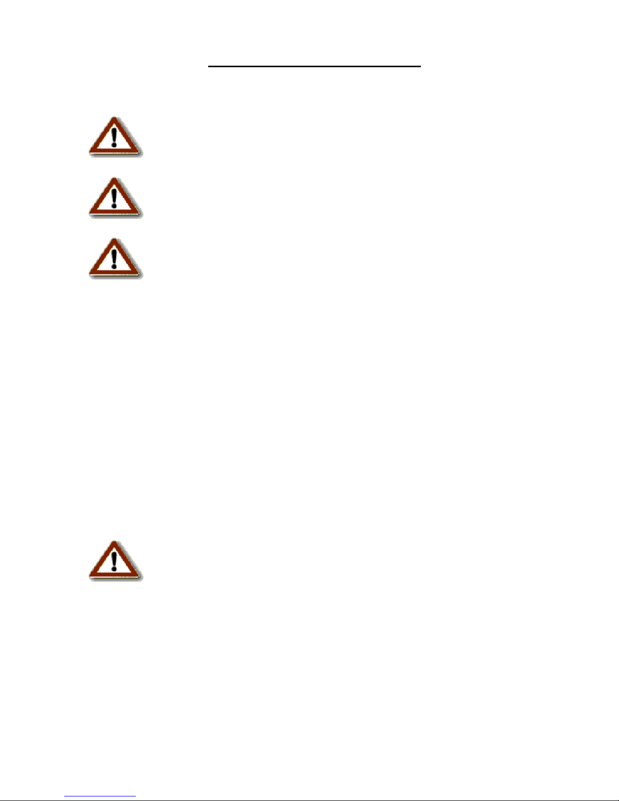
Control Transformer: The control transformer is rated at 24
vac, 40 va (1.6 amps @ 24vac).
Pump Bypass Timer: The pump bypass timer is a 24 vac, 3-
wire control. When energized the timer will bypass the flow
switch for 10 seconds by creating a circuit to the pump relay,
energizing the pump relay, and allowing the pump to operate
long enough to close the flow switch. In a normally operating
system, the flow switch will stay closed powering the pump
relay in series with the low and high pressure switches. Should
the flow switch open, the timer can only be reset by opening
and closing the chiller's line voltage disconnect.
System Delay Timer: The refrigerant timer is a 24 vac, 5-
minute delay on break timer. The normally closed contacts of the
timer energize the compressor contactor through the chilled
liquid solution control. When the chilled liquid solution control
contact opens, the timer delays by opening its contact for 5
minutes before resetting to the closed position.
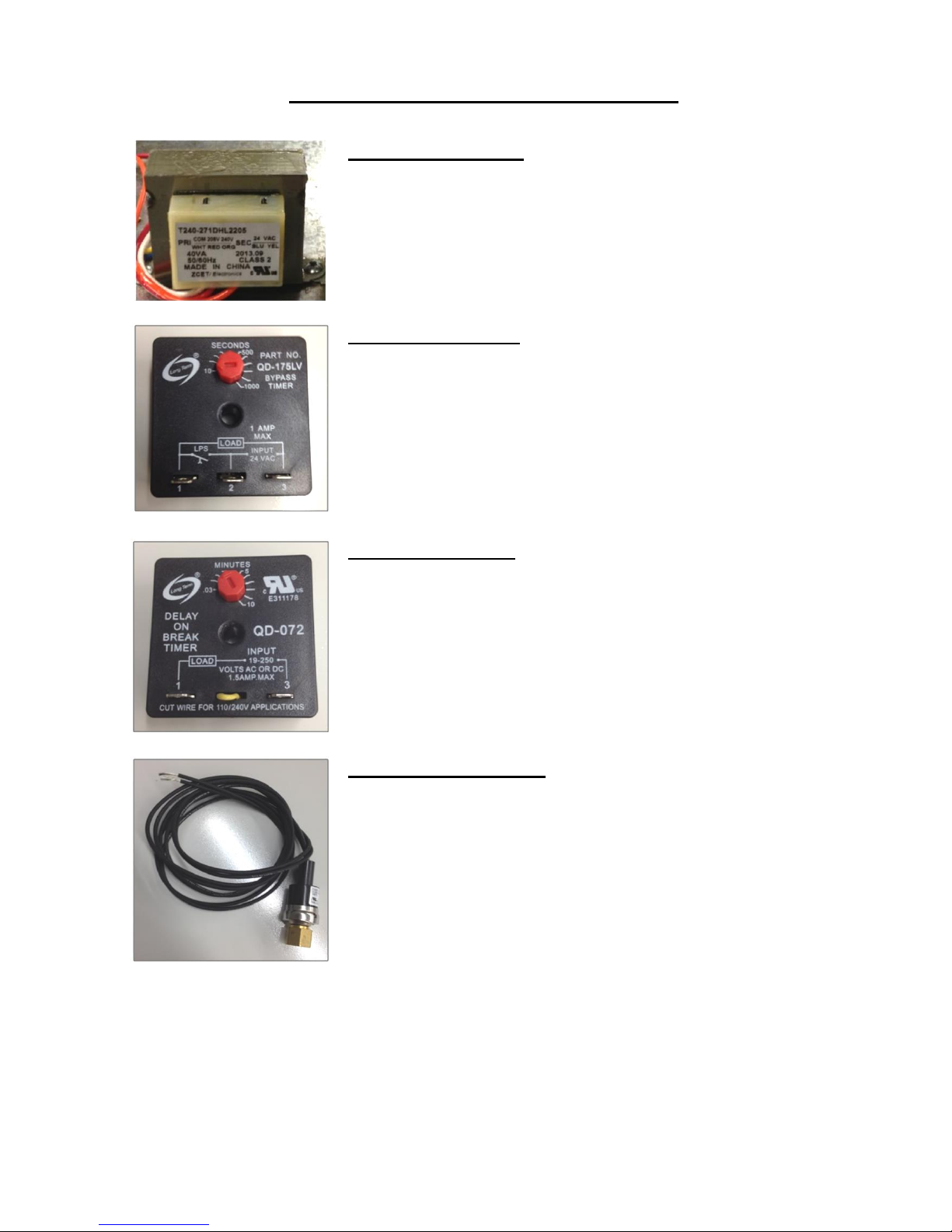
High Pressure Switch: The high pressure switch is an
automatic reset control that senses compressor discharge line
pressure. It opens at 400 PSIG and closes at 300 PSIG.
Page 7 of 28
Description of Electrical Controls
(Continued)
Low Pressure Switch: The low pressure switch is an automatic
reset that senses compressor suction line pressure. In early
production models, it opens at 40 PSIG and control closes at 80
PSIG. In the latest productions models, it opens at 10 PSIG and
control closes at 25 PSIG.
Flow Switch: The flow switch senses liquid solution flow. The
paddle of the switch is inserted through a fitting into the pump
discharge line. Liquid solution flow deflects the paddle and
closing the switch. The flow switch is position sensitive. The
arrow ↑ on the switch must point in the direction of liquid
solution flow. Maximum flow is not to exceed 14.4 GPM
Compressor Contactor: The compressor contactor energizes
the compressor through the two or three normally open contacts.
The contactor coil operates by closing the contacts when
energized by 24vac.
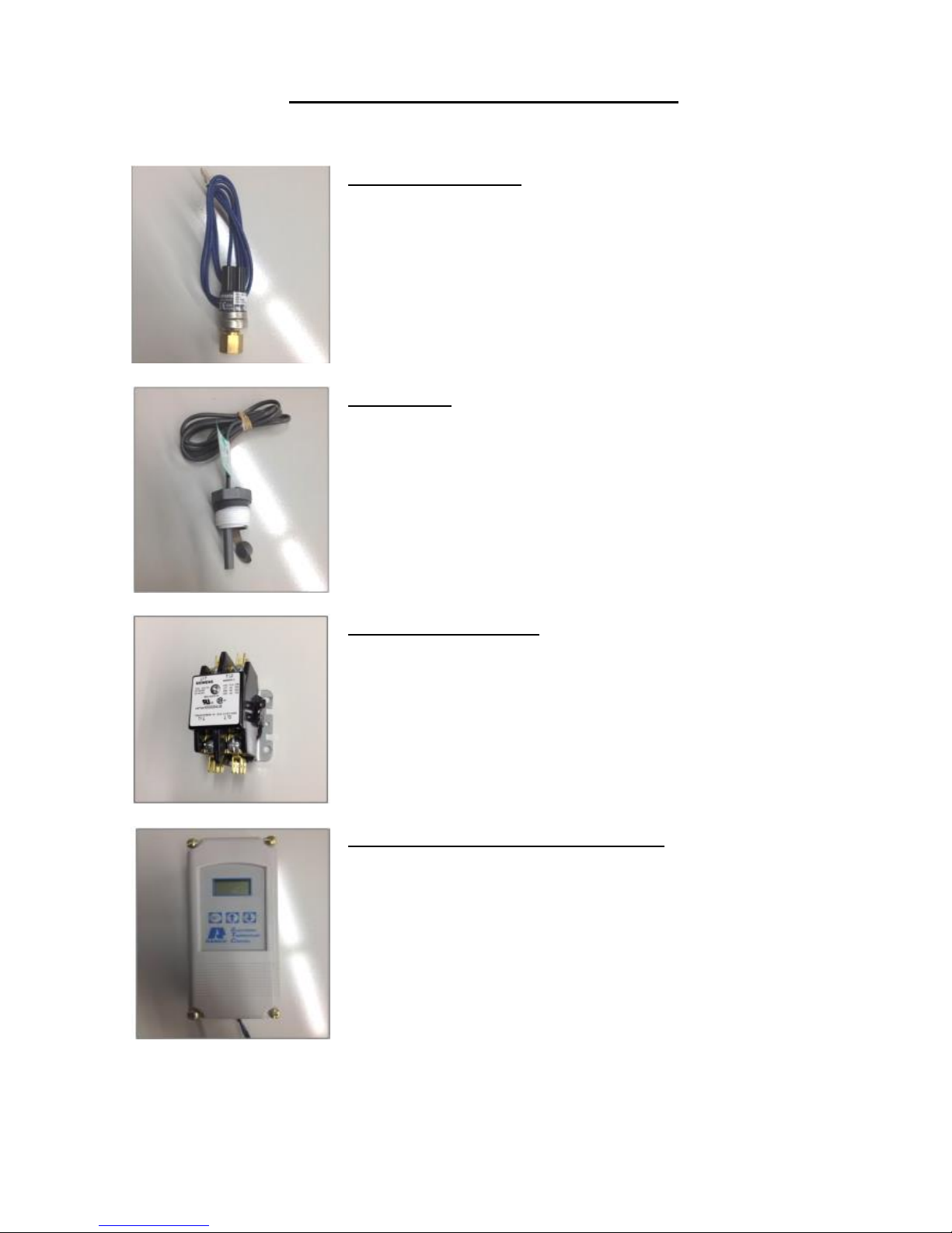
Liquid Solution Temperature Control: The liquid solution
temperature control is an adjustable, microprocessor-based
temperature control. This control receives temperature
information from a thermostat located on the liquid solution
supply line. A liquid crystal display continually indicates the
liquid solution temperature. The control is mounted inside the
chiller cabinet.
Page 8 of 28
 Loading...