

Multiaqua MAC120-02-N-R407, MHCCW04-00-03, MHCCW04-02-03, MHCCW04-00, MHCCW04-03 Operating Manual
...

Table of Contents (Hydronic)
About Us
System Modeling Software
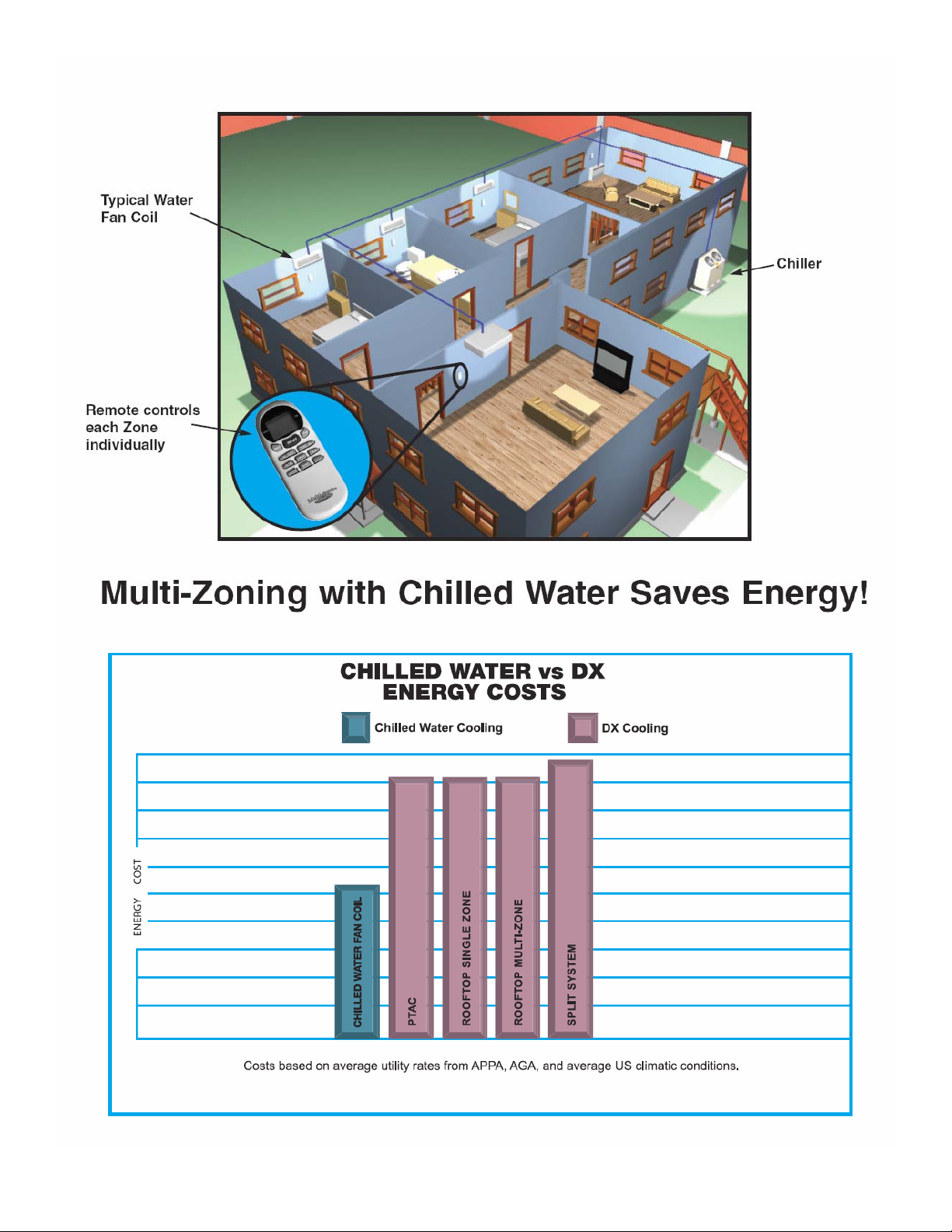
Multi-Zoning and Energy Cost
Features and Benefits
Water Products Overview
DX Products Overview
Accessory Products Overview
Equipment Sound Data
Page
1
2
3
4
5
6
7
8
MAC120 Air-Cooled Chiller
Nomenclature Breakdown
Guide Specifications
Product Specifications
Capacities
Installation and Operating Manual
Wiring Diagrams
Certified Drawing
MAC036,048 and 060 Air Cooled Chiller
Nomenclature Breakdown
Guide Specifications
Product Specifications
Capacities
Circulating Pump Curve
Installation and Operating Manual
Wiring Diagrams
Certified Drawing
MHCCW (Ceiling Concealed) 2-pipe Chilled Water with Electric Heat. 1 to 3 Tons
Nomenclature Breakdown
Guide Specifications
Product Specifications
Chilled Water Capacities
Hot Water Capacities
Electric Heat Capacities
CFM and Glycol Adjustments
Capacity Adjustment Factors
Installation and Operating Manual
Wiring Diagrams
Certified Drawing
9
10
11
13
15
17
34
43
44
45
46
48
50
56
57
74
83
84
85
86
88
89
94
99
100
101
102
113
116
MHNCCW (Ceiling Concealed) 4-Pipe Chilled and Hot Water. 1 to 3 Tons
Nomenclature Breakdown
Guide Specifications
Product Specifications
Chilled Water Capacities
Hot Water Capacities
CFM and Glycol Adjustments
Capacity Adjustment Factors
Installation and Operating Manual
Wiring Diagrams
Certified Drawing
117
118
119
121
122
127
132
133
134
145
147

Table of Contents (Hydronic Continued)
MCCW (Ceiling Concealed) 2-Pipe Chilled and Hot Water. 4 to 5 Tons
Nomenclature Breakdown
Guide Specifications
Product Specifications
Chilled Water Capacities
Hot Water Capacities
CFM and Glycol Adjustments
Capacity Adjustment Factors
Installation and Operating Manual
Wiring Diagrams
Certified Drawing
Page
148
149
150
152
153
155
157
157
158
169
170
MHWW (Hi-Wall) 2-Pipe Chilled and Hot Water. 1 to 3 Tons
Nomenclature Breakdown
Guide Specifications
Product Specifications
Chilled Water Capacities
Hot Water Capacities
Capacity and Glycol Adjustment Factors
Installation and Operating Manual
Wiring Diagrams
Certified Drawing
CFFWA (Universal Mount) 2-Pipe Chilled and Hot Water. 1 to 5 Tons
Nomenclature Breakdown
Guide Specifications
Product Specifications
Chilled Water Capacities
Hot Water Capacities
Capacity and Glycol Adjustment Factors
Installation and Operating Manual
Wiring Diagrams
Certified Drawing
CWA2 (Air Handler) 2-pipe Chilled Water with Electric Heat. 1.5 to 5 Tons
Nomenclature Breakdown
Guide Specifications
Product Specifications
Chilled Water Capacities
Hot Water Capacities
CFM and Glycol Adjustments
Capacity Adjustment Factors
Installation and Operating Manual
Wiring Diagrams
Certified Drawing
171
172
173
175
176
181
186
187
202
206
207
208
209
211
212
218
224
225
231
232
233
234
235
237
238
243
246
247
249
257
258
CWA4 (Air Handler) 4-pipe Chilled and Hot Water 2 to 5 Tons
Nomenclature Breakdown
Guide Specifications
Product Specifications
Chilled Water Capacities
Hot Water Capacities
CFM and Glycol Adjustments
Capacity Adjustment Factors
Installation and Operating Manual
Wiring Diagrams
Certified Drawing
259
260
261
263
264
268
269
270
271
279
280

Table of Contents (Direct Expansion)
MHCCX (Ceiling Concealed) DX with Electric Heat. 1 to 3 Tons
Nomenclature Breakdown
Guide Specifications
Product Specifications
Capacities
CFM Adjustments
Installation and Operating Manual
Wiring Diagrams
Certified Drawing
Page
281
282
283
285
287
288
289
300
304
MCCX (Ceiling Concealed) DX Only. 4 to 5 Tons
Nomenclature Breakdown
Guide Specifications
Product Specifications
Capacities
CFM Adjustments
Installation and Operating Manual
Wiring Diagrams
Certified Drawing
MHNCCX (Ceiling Concealed) DX with Hot Water. 1 to 3 Tons
Nomenclature Breakdown
Guide Specifications
Product Specifications
DX Capacities
CFM Adjustments
Glycol Adjustments
Capacity Adjustment Factors
Hot Water Capacities
Installation and Operating Manual
Wiring Diagrams
Certified Drawing
MHWX (Hi-Wall) DX Only. 1 to 3 Tons
Nomenclature Breakdown
Guide Specifications
Product Specifications
Capacities
Installation and Operating Manual
Wiring Diagrams
Certified Drawing
305
306
307
309
309
309
310
316
317
318
319
320
322
323
323
323
324
325
330
341
343
344
345
346
348
348
349
363
371
FSFCA (Universal Mount) DX Only. 1 to 5 Tons
Nomenclature Breakdown
Guide Specifications
Product Specifications
Capacities
Installation and Operating Manual
Wiring Diagrams
Certified Drawing
372
373
374
376
376
377
383
384

Table of Contents (Accessories)
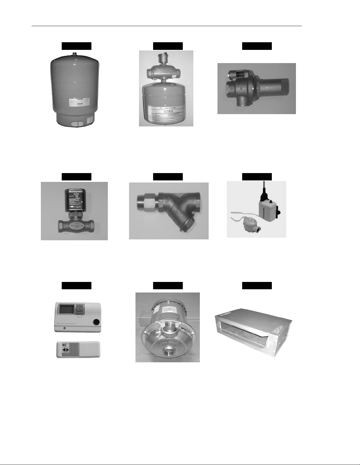
Accessories
Storage Tanks
Expansion Tank and Air Scoop
Liquid Solution Bypass Valve
Liquid Solution Control Valves
Condensate Pump
Control Thermostats
Wye Strainer
Circulating Pumps (1,1.5 & 2 HP)
Circulating Pump Curve (1,1.5 & 2 HP)
Circulating Pumps (.5 HP)
Circulating Pump Curve (.5 HP)
Ceiling Concealed Enclosures
Sample Piping
Banked Chiller Configuration
Page
385
387
388
389
391
392
395
396
397
398
399
400
407
408
409Warranty Information

About Us
Setting new industry standards is what we do best.
At Multiaqua, our commitment to creating innovative air conditioning products has made us one
of the most respected organizations in the industry. From concept to market, Multiaqua takes a
hands-on approach to ensure that each and every step meets our stringent standards of quality,
durability and dependability.
All Multiaqua products are designed with the future in mind. That’s why all air conditioning
products are flexible, which makes it easy to adapt to virtually all kinds of building applications.
Whether it’s residential or commercial air conditioning needs, Multiaqua has the products to
meet or exceed all expectations.
Manufacturing Excellence
Our beliefs in quality is more than just a practice, it is something we take great pride in. Our
quality management system is integrated with international quality requirements of ISO 9002.
That is why some of the biggest OEM names in the air conditioning industry use Multiaqua
products in their units. In fact, Multiaqua chillers were part of air conditioning system that won
first place awards in the Quality Home Comfort Awards Competition, which was created to
honor the best in residential comfort system design and application.
Our products are tested and certified to the UL, CE, ETL, UL1995 and ARI standards; the most
respected and stringent in the world.
Experience The Future
At Multiaqua, we invite you to come experience the future of air conditioning and see why more
and more companies are discovering the new standard of air conditioning excellence. And by
combining cost effectiveness, innovation and quality, Multiaqua will continue to provide air
conditioning products that will be the most sought after in the world.
1

Multiaqua Makes Hydronic System Design Easy
(
)
F
F
2
F
H
F
F
F
5
H
M
F
H
F
F
F
L
F
F
H
(
)
"
"
"
"
"
"
"
"
"
A
NAME: MULTIAQU
LOCATION: SOUTH CAROLINA
60000 BTU/H
12.6 GPM
ICL-1
55°
45°
100'
1.25 "
36000 BTU/H
ICL-
45°
1.25"
100'
7.6 GPM
145'
1.25
24000 BTU/
ICL-3
55°F
45°
1
145'
1.25"
5 GPM
1.25"145'
ICL-4
55°
45°F
1"
145'
1.25
24000 BTU/H
5 GPM
1"
5'
1"
1.5"
1.5
55°
1"
1.5
145'
2"
49 GPM
66.7 FT
145'
0'
BYPASS VALVE
2.5"
1'
2.5"
1.5
1"10'
73.1 GA
STOR-1
24000 BTU/
4.9 GP
ICL-
45°
11.5 GAL
ET-1
0'
1'
2
ICL-7
45°
55°
1.25"5'
1.25"5'
117000 BTU/
55°
45°
117 000 BTU/H
55°F
45°F
3600 0 BTU/H
7.6 GPM
9.8 TONS
24.5 GPM
50%
CH- 2
9.8 TONS
24.5 GPM
50%
CH-1
55°F
30000 BTU/
6.3 GPM
ICL-6
45°
55.4°F
1
1"5'
1"5'
1.5 "
5'
2
2.5"
5'
2.5"5'
1.25"5'
1'
1.5"1' 1.25"5'
5'
2"
P-1
Sample Design Shown
Introducing System Modeling Software
Multiaqua has teamed up with HVAC Solutions and would like to introduce the newest version of the HSS
Software. This software will contain a selection model that includes Mutiaqua’s Air Cooled Chillers, Fan Coils
and Air Handling Units.
HSS software will allow you to drag and drop components to design hydronic systems. It includes the necessary
piping, piping components and equipment. It is capable of exporting calculation reports, equipment schedules
and a bill of material. Visit www.multiaqua.com for software down load.
2
3

Ductless and Ducted Hydronic Air Conditioning & Heating Systems.
FOR MULTIZONING FACILITIES
• Zoning saves energy
• Better Control of Humidity
• Separate Climate in each Room
1. More Energy Efficient Thru Zoned Comfort Cooling.
2. Zoning Allows For Diversity.
3. Diversity and Load Calculations Allows For Reducing The Size of The Outdoor
Power Plant.
4. Banking Chillers Allows For Huge Efficiencies Thru Staging.
5. Helps Control The Growth Of Mold, Mildew and Fungus.
6. Low Installation Costs.
7. No Refrigerant Handling.
8. No Ductwork No Line Sets.
9. Heat & Cool with the Same Units.
10. No Line Length Limitations.
11. Unlimited Tonnage with Single Phase Power.
12. Easy To Expand System.
Think Water !!!
4
p
p
,
,
n
g
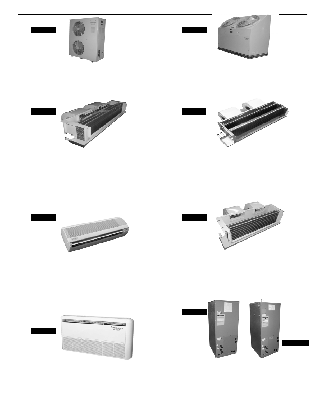
Water Product Overview
Page 44 Page 9
MAC036, 048 & 060 Air Cooled Chiller MAC120 Air Cooled Chiller
• 3, 4 & 5 Ton Air Cooled Chiller
• R 407c Refrigerant
• Horizontal Air Discharge
• Stainless Steel Pump Included
Page 84 Page 117
• 10 Ton Air Cooled Chiller
• Copeland Scroll Compressor Technology • Copeland Scroll Compressor Technology
• R 407c Refrigerant
• Vertical Air Discharge
• Two Stages of Coolin
MHCCW (Ceiling Concealed) Chilled Water 2-Pipe
With or Without Electric Heat
• 12,000- 36,000 BTUH
• Available with or without Electric Heat
• Ceiling Concealed Design for Clean Installation
• Removes Equipment from Conditioned Space
• Heavy Gauge Metal Cabinet
• Powder Painted Galvanized Steel
• Field Reversible Hand of Connection Coil
• Manual Air Vents
• Discharge May be Ducted for Small Spaces
Page 171 Page 148
MHWW (Hi-Wall) Chilled/Hot Water 2-Pipe
• 9,000- 36,000 BTUH
• High Wall Mounting
• Attractive Seamless Appliance Design
• Cleanable Air Filter Provided
• Wireless Infrared Remote Included
• Wired Controller Option
MHNCCW (Ceiling Concealed) Chilled/Hot Water 4-Pipe
• 12,000-36,000 BTUH
• Ceiling Concealed Design for Clean Installation
• Removes Equipment from Conditioned Space
• Heavy Gauge Metal Cabinet
• Powder Painted Galvanized Steel
• Double Field Reversible Hand of Connection Coil
• Manual Air Vents
• Discharge May be Ducted for Small Spaces
MCCW (Ceiling Concealed) Chilled/Hot Water 2-Pipe
• 48,000 – 60,000 BTUH
• Ceiling Concealed Design for Clean Installation
• Removes Equipment from Conditioned Space
• Heavy Gauge Metal Cabinet
• Powder Painted Galvanized Steel
• Manual Air Vents
• Discharge May be Ducted for Small Spaces
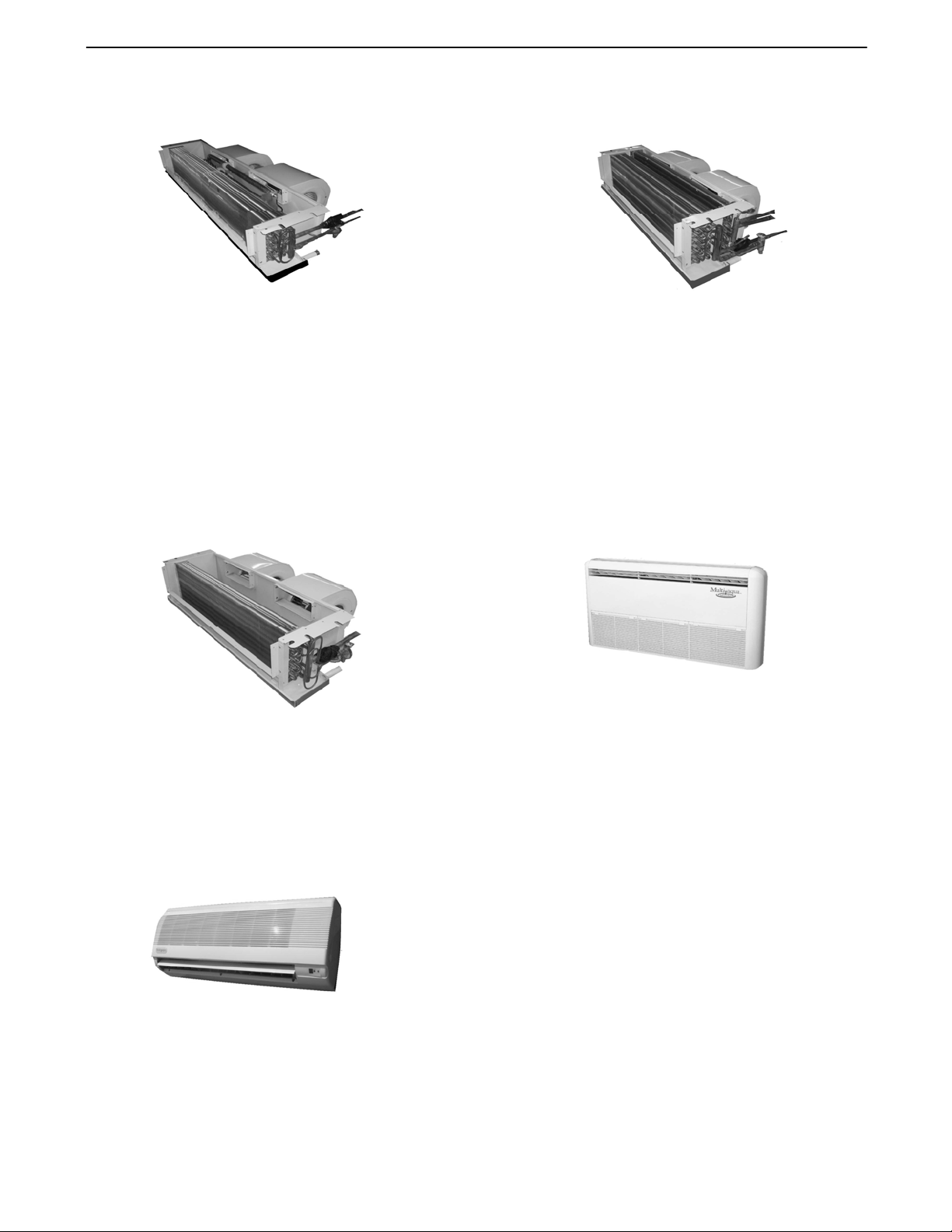
Page 233
Page 207
Page 259
CWA2 With or Without Electric Heat 2-Pipe
CFFWA Universal Mount Fan Coil 2-Pipe
• 12,000- 60,000 BTUH
• Floor
Low Wall or Horizontal Ceiling Mounting • Up Flow, Left or Right Hand Horizontal Installatio
• Attractive Modular Design
• Cleanable Air Filter Included
• Optional Wireless Remote
CWA4 Chilled & Hot Water 4-Pi
• Available in 2 or 4-Pi
• 18
000- 60,000 BTUH
• Equipped with R4.2 Insulation
• CWA2 in 208/240-1-60 & CWA4 in 120-1-60
• Electric or Hot Water Heat
5
e Configuration
e
i
DX Product Overview
DX Fan Coils are Compatible with R410a Refrigerant and are 13 SEER Compatible
All DX Coils come Shipped From the Factory with a TXV Installed.
MHCCX (Ceiling Concealed) DX 2-Pipe
With or Without Electric Heat
• 12,000-36,000 BTUH
• Available with or without Electric Heat
• Ceiling Concealed Design for Clean Installation
• Removes Equipment from Conditioned Space
• Heavy Gauge Metal Cabinet
• Powder Painted Galvanized Steel
• Field Reversible Hand of Connection Coil
• TXV Provided
• Discharge May be Ducted for Small Places
•13 SEER Compatible
MCCX (Ceiling Concealed) DX
• 48,000-60,000 BTUH
• Ceiling Concealed Design for Clean Installation
• Removes Equipment from Conditioned Space
• Heavy Gauge Metal Cabinet
• Powder Painted Galvanized Steel
• TXV Provided
• Discharge May be Ducted for Small Spaces
MHNCCX (Ceiling Concealed) DX 4-Pipe
with Hot Water
• 12,000-36,000 BTUH
• Ceiling Concealed Design for Clean Installation
• Removes Equipment from Conditioned Space
• Heavy Gauge Metal Cabinet
• Powder Painted Galvanized Steel
• Double Field Reversible Hand of Connection Coil
• TXV Provided
• Discharge May Be Ducted for Small Places
• Hot Water Heating Coil
•13 SEER Compatible
FSFCA (Universal Mount) DX or Heat Pump
• 12,000- 60,000 BTUH
• Floor, Low Wall or Horizontal Ceiling Mounting
• Attractive Modular Design
• Cleanable Air Filter Included
• Optional Wireless Remote
• TXV Provided
•13 SEER Compatible
MHWX (Hi-Wall) DX or Heat Pump
• 9,000- 36,000 BTUH
• High Wall Mounting
• Attractive Seamless Appliance Des
• Cleanable Air Filter Provided
• Wireless Infrared Remote Included
• Wired Control Option
6
Accessories Overview
Page 385 Page 387 Page 388
Storage Tanks
20 & 42 Gallon
Page 389 Page 395 Page 391
Motorized Valves
2 & 3-Way
Page 392 Page 396 Page 398
Expansion Tank & Air Scoop Liquid Solution Bypass Valve
Condensate PumpWye Strainer
Thermostats
EnclosuresCirculating Pumps
7

January 2008
Multiaqua Equipment Sound Levels
The following will detail the “Sound Levels” of the Multiaqua equipment line.
Air Cooled Chillers
MAC 036, 048, 060 Chillers: 69 dbs (A)
MAC120 Chillers: 75 dbs (A)
Hi-Wall Fan Coils
MHWX-09 / MHWW-09: DX and chilled water Hi-Wall fan coils: 42 dbs (A).
MHWX-12 / MHWW-12: DX and chilled water Hi-Wall fan coils: 43 dbs (A).
MHWX-18 / MHWW-18: DX and chilled water Hi-Wall fan coils: 45 dbs (A).
MHWX-24 / MHWW-24: DX and chilled water Hi-Wall fan coils: 46 dbs (A).
MHWX-36 / MHWW-36: DX and chilled water Hi-Wall fan coils: 48 dbs (A).
Universal Mount Fan Coils
FSFCA-04 / CFFWA-04: DX and chilled water Universal Mount fan coils: 42 dbs (A).
FSFCA-06, 08 / CFFWA-06, 08: DX and chilled water Universal Mount fan coils: 44 dbs (A).
FSFCA-10 / CFFWA-10: DX and chilled water Universal Mount fan coils: 46 dbs (A).
FSFCA-10, 12 / CFFWA-10, 12: DX and chilled water Universal Mount fan coils: 48 dbs (A).
FSFCA-16, 20 / CFFWA-16, 20: DX and chilled water Universal Mount fan coils: 50 dbs (A).
Hideaway Fan Coils
MHCCX-04 / MHCCW-04: DX / chilled water with electric heat Hideaway fan coils: 42 dbs (A)
MHCCX-06 / MHCCW-06: DX / chilled water with electric heat Hideaway fan coils: 44 dbs (A)
MHCCX-08 / MHCCW-08: DX / chilled water with electric heat Hideaway fan coils: 46 dbs (A)
MHCCX-10 / MHCCW-10: DX / chilled water with electric heat Hideaway fan coils: 48 dbs (A)
MHCCX-12 / MHCCW-12: DX / chilled water with electric heat Hideaway fan coils: 49 dbs (A)
MHNCCX-04 / MHNCCW-04: DX / chilled water with hot water heat Hideaway fan coil: 40 dbs (A)
MHNCCX-06 / MHNCCW-06: DX / chilled water with hot water heat Hideaway fan coil: 42 dbs (A)
MHNCCX-08 / MHNCCW-08: DX / chilled water with hot water heat Hideaway fan coil: 44 dbs (A)
MHNCCX-10 / MHNCCW-10: DX / chilled water with hot water heat Hideaway fan coil: 46 dbs (A)
MHNCCX-12 / MHNCCW-12: DX / chilled water with hot water heat Hideaway fan coil: 48 dbs (A)
MCCX-16 / MCCW-16: DX and chilled water Hideaway fan coil. 46 dbs (A)
MCCX-20 / MCCW-20: DX and chilled water Hideaway fan coil. 46 dbs (A)
Disclaimer: Specifications are subject to change without notice. All tests conducted in nonechoic chambers. Sound levels were measured at five feet from the unit. Levels were measured
using free air delivery.
8
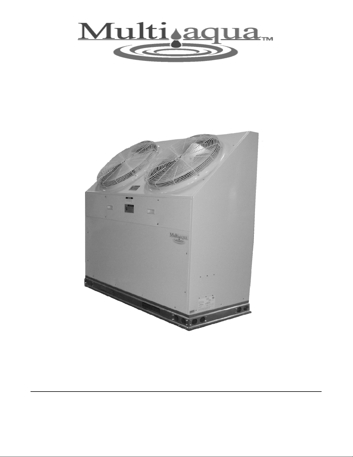
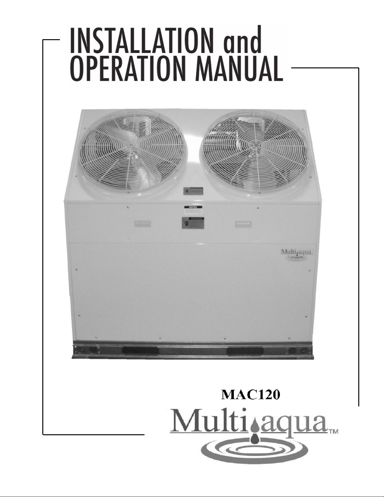
MAC120 Air-Cooled Chiller
Air-Cooled Chillers for Global Residential
and Light Commercial MicroClimates
9
MAC120 NOMENCLATURE BREAKDOWN
MAC120 - XX - X - R407
10-Ton
Air-Cooled Chiller
Voltage
01 = 208/230-1-50/60
02 = 208/230-3-50/60
03 = 380/460-3-50/60
Available Model Numbers
MAC120-01-N-R407
MAC120-01-L-R407
MAC120-02-N-R407
MAC120-02-L-R407
MAC120-03-N-R407
MAC120-03-L-R407
Accessory
Options
N= No Options
L= Low Ambient Kit
10

HVAC Guide Specifications
Air-Cooled Liquid Chiller
Nominal Size:
10 Tons
Multiaqua Model Number:
MAC120-01-N-407, MAC120-01-L-407
MAC120-02-N-407, MAC120-02-L-407
MAC120-03-N-407, MAC120-03-L-407
Part 1-General
1.01 System Description
Multiaqua air-cooled liquid chillers are designed using scroll compressors and low sound condenser fans.
1.02 Quality Assurance
A. Certified in accordance with U.L. Standard 95, latest version (U.S.A.)
B. Construction shall comply with ASHRAE 15 Safety Code, NEC and ASME applicable codes. (U.S.A.
Codes)
C. Manufactured in a facility registered to ISO 9002, Manufacturing Quality Standard.
D. ETL certified.
E. Fully load tested at the factory.
F. Damage resistant packaging.
1.03 Delivery, Storage and Handling
A. Packaged and readied for shipment from the factory.
B. Controls shall be capable of withstanding 150°F storage temperatures in the control compartment.
C. Stored and handled per manufacturer’s rec o mmendations.
Part 2-Product
2.01 Equipment
A. General:
1. Unit shall be a factory assembled and tested air-cooled liquid chiller.
2. Shall be assembled on heavy gauge steel mounting/lifting rails.
3. Contained within the unit cabinet shall be all factory wiring, piping, controls, refrigerant charge
(R407c), POE oil and special accessories required prior to start up.
4. Brass body strainer with 20 mesh screen and blow down shall be supplied in cabinet as a
field installable accessory.
B. Unit Cabinet:
1. Composed of heavy gauge galvanized steel casing with a baked polyester powder.
2. Capable of withstanding 500-hour salt spray test in accordance with the ASTM (U.S.A.) standard.
C. Condenser Fans:
1. 4-blade, aluminum construction and shall be dynamically balanced and corrosion resistant.
2. Discharge air at a 45° vertical angle.
3. Motors and blades shall be protected by coated steel wire safety guards.
D. Fan Motors:
1. Condenser fan motors shall be single speed, direct drive.
2. Totally enclosed.
3. Permanently lubricated sleeve bearings and Class F insulation.
4. Internal overload protection.
E. Compressors:
1. Unit shall contain two fully hermetic scroll compressors.
2. Direct-drive, 3500 rpm (60Hz)
3. Compressor motor shall be suction gas cooled.
4. Internal motor protection.
5. Externally protected by low and high pressure cutout devices.
6. Individual vibration isolators .
11

F. Pump:
1. Unit shall be capable of incorporating a field installed chilled liquid solution pu mp.
(Space restricted)
2. Unit shall have provisions to allow for chilled liquid solution piping to the exterior of the cabinet.
G. Evaporator:
1. Evaporator shall have two independent r ef rigerant circuits.
2. Rated for a refrigerant side working pressure of 450 psig and a maximum water side working
pressure of 60 psig.
3. Single pass, ANSI type 316 stainless steel, brazed plate construction.
4. Externally insulated with closed cell, elastomeric foam. (ASTM518)
H. Condenser:
1. Condenser coil shall be air-cooled with integral subcooler.
2. Two independent refrigerant circuits.
3. Constructed of rifled copper tubing mechanically bonded to aluminum fins.
4. Cleaned and dehydrated.
5. Factory leak tested to 450 psig.
I. Refrigerant Circuits:
1. Each circuit shall contain a sight glass, liquid line filter, thermal expansion valve,
refrigerant charge of R407c and POE compressor oil.
Part 3-Controls and Safeties
3.01 Controls
A. Chiller shall be completely factory wired and tested.
B. Capacity control shall be based on leaving chilled liquid solution temperature.
1. Temperature accuracy shall be + - 1.0°F.
2. Controls shall be capable of staging the two compressors.
C. Controls shall include the following components.
1. 24vac transformer to serve all controllers relays and control components.
2. Microprocessor based liquid solution temperature controller.
3. Leaving water temperature thermistor.
4. Pump bypass timer.
5. Compressor recycle timer.
6. Optional fan cycling control for low ambient operation.
7. Chilled liquid solution flow switch.
3.02 Safeties
A. Unit shall be equipped with thermistors and all necessary components in conjunction with the
control system to provide the following protectants.
1. Low refrigerant pressure.
2. High refrigerant pressure.
3. Low chilled liquid solution temperature.
4. Low chilled liquid solution flow.
5. Thermal overload.
6. Short cycling.
Part 4-Operating Characteristics:
4.01 Temperatures
A. Unit shall be capable of starting and running at outdoor temperatures from 55°F to 120°F.
B. Optional Low Ambient Kit shall allow starting and running at outdoor temperatures to -20
field supplied and installed crank case heater must be used when operating at these temperatures.
C. Unit shall be capable of starting up with a maximum 80°F and a sustained 70°F entering fluid
solution temperature to the evaporator.
D. Minimum 10% Glycol solution is required. For outdoor temperatures below 32°F, reference
MAC Glycol Solution Data table.
4.02 Electrical Requirements
A. Primary electrical power supply shall enter the unit at a single location.
B. Electrical power supply shall be rated to withstand 120°F operating ambient temperature.
C. Units shall be available in 1 or 3-phase power at the voltages shown in the equipment electrical data.
D. Control points shall be accessed through terminal block.
12
°F. A
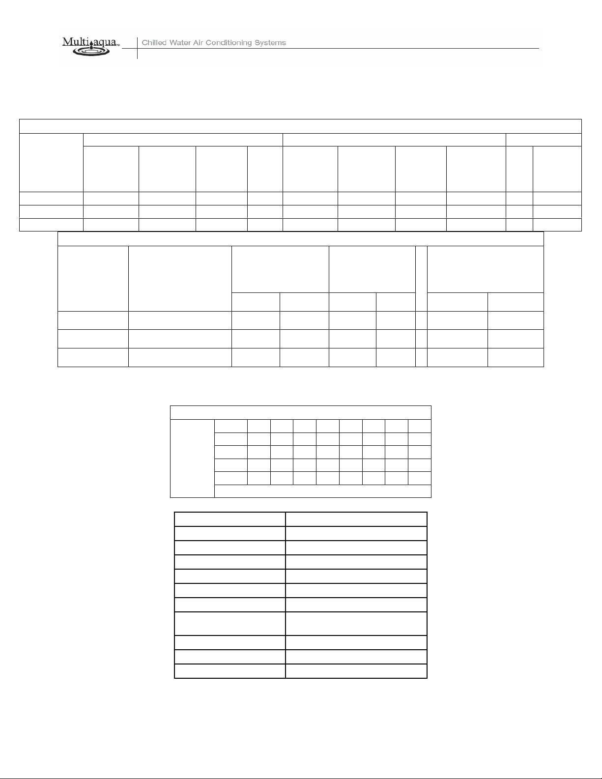
MAC120 Product Specifications
Physical Data
Condenser Coil Chiller Weight (lbs)
Model
Number
Height
(in)
Length
(in)
MAC120-01 52.5 48 3/8 3 60 58.25 25.25 104 oz x 2 650 700
MAC120-02 52.5 48 3/8 3 60 58.25 25.25 104 oz x 2 650 700
MAC120-03 52.5 48 3/8 3 60 58.25 25.25 104 oz x 2 650 700
Copper
Tubing
Diameter
(in)
Coil
Rows
Height
(in)
Electrical Data
Length
(in)
Width
(in)
Refrigerant
R407c
Net Shipping
Compressor
Model
Number
Volts/ Phase/ Hertz
(Qty 2)
(RLA) (LRA) (RLA) (RPM)
MAC120-01 208/230-1-50/60 32.1 x 2 169 x 2 2.3 x 2 900
MAC120-02 208/230-3-50/60 19.3 x 2 137 x 2 2.3 x 2 900
MAC120-03 380/415/460-3-50/60 10 x 2 75 x 2 1.6 x 2 900
Condenser Fan
Motor
(Qty 2)
Fuse or HACR Circuit
44.73 x 2
Breaker
Minimum
Amps
“See note 1”
48.03
“See note 2”
25.70
“See note 2”
Maximum
Amps
75 x 2
“See note 1”
65
“See note 2”
35
“See note 2”
Note:
1. MAC120-01 has two independent line voltage terminations.
2. MAC120-02 & MAC120-03 has one independent line voltage termination.
Copper Wire Size (1% Voltage Drop)
200 6 4 4 4 3 3 2 2
150 8 6 6 4 4 4 3 3
100 10 8 8 6 6 6 4 4
50 14 12 10 10 8 8 6 6
Supply Wire
15 20 25 30 35 40 45 50
Length in Feet
Supply Circuit Ampacity
Compressor Copeland Scroll
Refrigerant R407c
Heat Exchanger Brazed Plate
Max Flow Rate 28.8 gpm
Min Flow Rate 18 gpm
Supply Water Temp 44°
Return Water Temp 54°
Minimum System
Solution Content
50 Gallons
Expansion Tank Size 3% of Total System
Water Connections 1 3/8" OD Supply & Return
Internal Pressure Drop 18 ft of head
Multiaqua chillers are designed to operate exclusively with R407c refrigerant in a self-contain ed, pre-charged refrigerant system. Do
not access the closed refrigerant circuit for any reason other than after-sale, after installation component replacement. Routine
maintenance and service is to be performed by qualified personnel only.
These specifications are subject to change without notice.
13
MAC120 Product Specifications
MAC120 Capacity / Watts / EER*
TONS 9.4 9.0 8.8 8.7 8.7
KILOWATTS 10.9 11.5 11.5 12.1 12.4
EER 10.35 9.39 9.18 8.63 8.42
* Refrigerant system performance only, pump data not included.
82 95 100 105 110
MAC120 Glycol Solution Data
Propylene Glycol %
10% x 1.020 x 0.99 26°F x 1.01
20% x 1.028 x 0.98 18°F x 1.03
30% x 1.036 x 0.98 8°F x 1.07
40% x 1.048 x 0.97 -7°F x 1.11
50% x 1.057 x 0.96 -29°F x 1.16
Example: 30% glycol solution.
Maximum Flow Rate = 12gpm x 1.036
System capacity x .98
*Use Propylene Glycol Only
Water
Flow
Capacity Min. Ambient Temp GPM Adjustment= 100% Capacity
Important
If the outside temperature is expected to fall below freezing (32°F) in the area the Multiaqua chiller is to be
installed; the installer must take the following precautions. Failure to do so will void the warranty.
To not engage in cold ambient mitigation will result in the failure of components such as the heat
exchanger, piping, circulating pump, etc… and or property damage.
• Keep the liquid solution at a minimum of 10% percent Propylene Glycol even in areas where there is no
danger of freezing.
• The percentage amount of glycol recommended is dependent on the expected ambient temperatures and the
solution makeup recommendation of the glycol manufacturer. Refer to the MAC120 Glycol Solution Data table
above.
• Ensure the system circulating pump is in a constant energized mode to keep a continuous circulation of liquid
solution.
The Multiaqua chiller is a self-contained air-cooled condenser, coupled with an insulated brazed plate heat
exchanger (evaporator). The system utilizes a scroll compressor to circulate refrigerant between the condenser
and heat exchanger. The refrigerant is metered into the heat exchanger with a thermal expansion valve.
Protecting the system are high and low pressure switches as well as a pump flow switch.
Liquid solution (water and Propylene Glycol; minimum 10 % is required) is circulated through the heat
exchanger by an externally mounted pump. The liquid solution flows through the heat exchanger to the system
supply piping and on to the air handlers.
Low ambient kits are available for operating ambient temperatures down to -20 degrees Fahrenheit. A field
supplied and installed crankcase heater must be installed when operating at these temperatures. The low
ambient kits consist of an ICM 325 (+) ICM (175) for single and three phase 208/230 vac chillers. For the three
phase 380/460 vac chillers a pressure activated fan control is used.
These specifications are subject to change without notice.
Outdoor Air °F
14
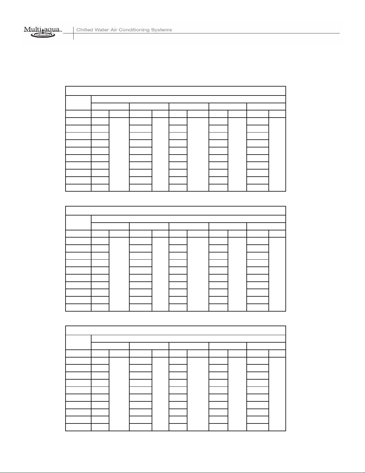
MAC120 Cooling Performance Data
MAC120 CAPACITIES with 0% Glycol
LWT (°F)
35 7.9 7.6 7.4 7.3 7.1
40 8.8 8.4 8.2 8.1 8.1
42 9.1 8.7 8.5 8.4 8.4
44 9.4 9.0 8.8 8.7 8.7
45 9.6 9.2 9.0 8.8 8.8
46 9.7 9.3 9.1 9.0 9.0
48 10.1 9.7 9.4 9.3 9.3
50 10.4 10.0 9.7 9.6 9.6
55 11.3 10.9 10.5 10.4 10.3
60 12.3 11.8 11.4 11.2 11.1
82 95 100 105 110
TONS GPM TONS GPM TONS GPM TONS GPM TONS GPM
28.8 28.8 28.8
MAC120 CAPACITIES with 10% Glycol
LWT (°F)
35 7.8 7.5 7.3 7.2 7.0
40 8.7 8.3 8.1 8.0 8.0
42 9.0 8.6 8.4 8.3 8.3
44 9.3 8.9 8.7 8.6 8.6
45 8.5 9.1 8.9 8.7 8.7
46 9.6 9.2 9.0 8.9 8.9
48 10.0 9.6 9.3 9.2 9.2
50 10.3 9.9 9.6 9.5 9.5
55 11.2 10.7 10.4 10.3 10.2
60 12.1 11.6 11.2 11.0 10.9
82 95
TONS GPM TONS GPM TONS GPM TONS GPM TONS GPM
28.8 28.8
ENTERING AIR TEMPERATURE (°F)
28.8
ENTERING AIR TEMPERATURE (°F)
100 105
28.8 28.8 28.8
28.8
110
MAC120 CAPACITIES with 20% Glycol
LWT (°F)
35 7.7 7.4 7.2 7.1 6.9
40 8.6 8.2 8.0 7.9 7.9
42 8.9 8.5 8.3 8.2 8.2
44 9.2 8.8 8.6 8.5 8.5
45 9.4 9.0 8.8 8.6 8.6
46 9.5 9.1 8.9 8.8 8.8
48 9.9 9.5 9.2 9.1 9.1
50 10.1 9.8 9.5 9.4 9.4
55 11.1 10.6 10.2 10.1 10.0
60 12.0 11.5 11.1 10.9 10.8
82 95 100 105 110
TONS GPM TONS GPM TONS GPM TONS GPM TONS GPM
28.8 28.8 28.828.8
ENTERING AIR TEMPERATURE (°F)
These specifications are subject to change without notice.
15
28.8
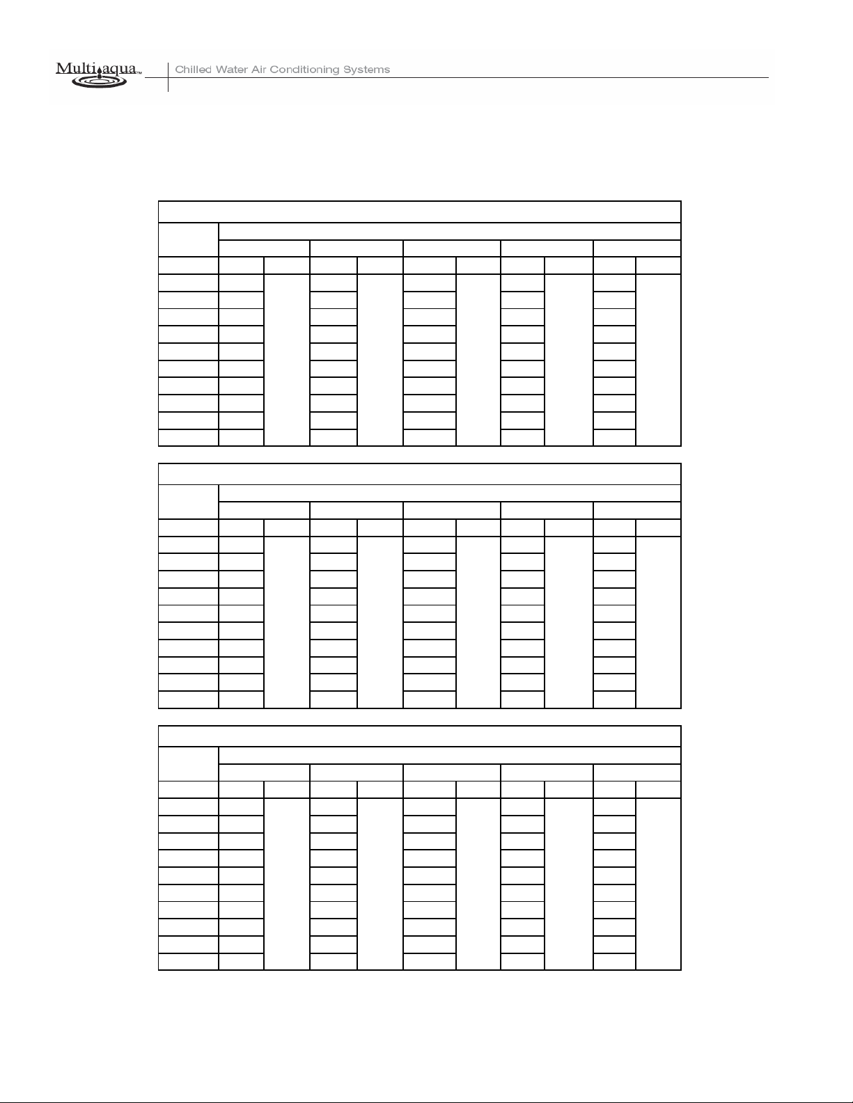
MAC120 Cooling Performance Data
MAC120 CAPACITIES with 30% Glycol
LWT (°F)
35 7.7 7.4 7.2 7.1 6.9
40 8.5 8.1 8.0 7.9 7.9
42 8.8 8.4 8.2 8.1 8.1
44 9.1 8.7 8.5 8.4 8.4
45 9.3 8.9 8.7 8.5 8.5
46 9.4 9.0 8.8 8.7 8.7
48 9.8 9.4 9.1 9.0 9.0
50 10.1 9.7 9.4 9.3 9.3
55 11.0 10.6 10.2 10.1 10.0
60 11.9 11.5 11.1 10.9 10.8
82
TONS GPM TONS GPM TONS GPM TONS GPM TONS GPM
MAC120 CAPACITIES with 40% Glycol
LWT (°F)
35 7.6 7.3 7.1 7.0 6.8
40 8.5 8.1 7.9 7.8 7.8
42 8.8 8.4 8.2 8.1 8.1
44 9.1 8.7 8.5 8.4 8.4
45 9.3 8.9 8.7 8.5 8.5
46 9.4 9.0 8.8 8.7 8.7
48 9.8 9.4 9.1 9.0 9.0
50 10.0 9.7 9.4 9.3 9.3
55 10.9 10.5 10.1 10.0 9.9
60 11.9 11.4 11.0 10.8 10.7
82 95 100 105 110
TONS GPM TONS GPM TONS GPM TONS GPM TONS GPM
28.8 28.8 28.8
ENTERING AIR TEMPERATURE (°F)
95 100 105 110
28.8 28.828.8 28.8 28.8
ENTERING AIR TEMPERATURE (°F)
28.8 28.8
MAC120 CAPACITIES with 50% Glycol
LWT (°F)
35 7.5 7.3 7.1 7.0 6.8
40 8.4 8.0 7.8 7.7 7.7
42 8.7 8.3 8.1 8.0 8.0
44 9.0 8.6 8.4 8.3 8.3
45 9.2 8.8 8.6 8.4 8.4
46 9.3 8.9 8.7 8.6 8.6
48 9.7 9.3 9.0 8.9 8.9
50 9.9 9.6 9.3 9.2 9.2
55 10.8 10.4 10.0 9.9 9.8
60 11.8 11.3 10.9 10.7 10.6
82 95 100 105 110
TONS GPM TONS GPM TONS GPM TONS GPM TONS GPM
These specifications are subject to change without notice.
ENTERING AIR TEMPERATURE (°F)
28.8 28.828.8 28.8 28.8
16
17

Table of Contents
Page
Introduction 19
System Description & Sequence of Operation 20
Electrical & Physical Data 21
Description of Electrical Controls 23
Chiller Controls Sequence of Operation 25
Refrigeration System Operation 26
Description of Refrigeration Components 26
Piping System Components 28
Layout & Design 29
Banked Chiller Configuration 30
Installation Notes 31
Propylene Glycol Content 32
Expansion Tank 32
Filling the System with Propylene Glycol 33
Air Elimination 33
18
Multiaqua Chiller Manual
The Multiaqua Chiller System is the only air conditioning/refrigeration system of its kind in the world
today offering the degree application flexibility described in the following manual.
The Multiaqua Chiller System is not only unique in its application flexibility; it is unique in superior
quality, rated capacities and rugged durability. When installed in accordance with these instructions the
system will deliver years of trouble free service.
Proper equipment sizing, piping design and installation are critical to the performance of the chiller. This
manual is meant to be a “how to” introduction to piping and installing the Multiaqua Chiller System.
MAC120 Chiller Features
• Copeland Scroll Compressors
• Advanced Motor Protection
• Loss of Flow Protection
• Control Power Transformer
• Low Ambient Option
• Integrated Chilled Solution Pump Control
• Flow Switch
• Strainer Connection Kit
• Painted Metal Condenser Protector Grille
• Dual Refrigeration Circuits and Single Liquid Solution Circuit
RECOGNIZE THIS SYMBOL AS AN INDICATION OF IMPORTANT SAFETY OR
INSTRUCTION RELATED INFORMATION.
Web site information addresses are supplied throughout this manual for piping and accessory information.
The plumbing industry also has pressure drop information on ferrous and copper piping systems.
The following sections will describe each component and how it functions within the system. Installation
information is supplied where appropriate. The piping design section will explain the design and layout
the piping system from a “how to” perspective. Following the examples provided will enable the installer
to determine the correct pipe and accessory sizing, as well as equipment location. It is important to know
before installation if the proposed system will operate correctly and by doing a formal layout of a new
application or review of an existing piping system will make that determination.
Throughout this manual the term “liquid solution” is used in place of water. The chiller circulates a
solution of water and Propylene Glycol.
It is essential to operate the system with a minimum of 10% glycol. DO NOT OPERATE THIS
SYSTEM USING WATER ALONE.
For proper liquid solutions mix ratios, refer to page 14 or the glycol manufacture’s recommended mix
ratios.
19
System Description & Sequence of Operation
The Multiaqua Chiller is a self-contained, air-cooled condenser, coupled with an insulated brazed plate
heat exchanger (evaporator). The system utilizes scroll comp ressors to circulate refrigerant between the
condenser and heat exchanger. The refrigerant is metered into the heat exchanger with a thermostatic
expansion valve. Protecting the system are high and low pressure switches as well as a pump flow switch.
Liquid solution (water and Propylene Glycol is circulated through the heat exchanger by a field supplied
pump. The liquid solution flows through the heat exchanger to the system supply piping and on to the air
handlers.
A solenoid-operated, motorized valve or circulator controls the flow of the chilled liquid solution through
the air handlers. The valves or circulators can be actuated by a variety of different control schemes.
Liquid solution temperature is controlled by a chiller mounted digital electronic controls. A system
sequence of operation, individual control description, troubleshooting information and a schematic are
included in the controls section.
It must be recognized that ferrous pipe may cause acceleration deterioration of the brazed
plate heat exchanger and could void the heat exchanger warranty.
Cooling load Diversity
Equipment sizing for a chilled liquid solution system can utilize Cooling Load Diversity. Diversity is
described as the actual amount of cooling needed (heat load) by various sections of a structure at a given
time. Conventional air conditioning systems are designed for the highest structure heat load. The
conventional system determines and selects equipment based on the peak heat load demanded by the
structure. A system sized to take advantage of diversity would determine the heat load by the time of day,
building exposure and usage. As an example the sections of a structure facing west, demand more cooling
in the afternoon, than sections facing east. The opposite of this is true in the morning, where the east
section is exposed to a higher heat load requiring more cooling. Utilizing diversity the chiller system
would adapt to the needs of each side of the structure during peak demand by delivering more cooling to
that area and less to the areas that do not need it. A structure utilizing a conventional DX system, requires
8 tons of cooling at peak load, could utilize a much smaller capacity system (potentially 4 or 5 tons) if the
system installed could take advantage of load diversity, which would supply the necessary amount of
cooling to the space, as and when needed instead of keeping a larger capacity available at all times.
Cooling load diversity can best be determined by referring to ACCA. (Air Conditioning Contractors of
America) Manual “J”, Refer to the appendix A-2, Multi-Zone Systems. ACCA’s Internet address is
http://www.acca.org/
Because of diversity a Multiaqua Chiller can serve more total air handler tonnage than chiller capacity. A
10-ton chiller may be delivering chilled liquid solution to 15 or more tons of air handler capacity. Because
of cooling load diversity, the building does not need equal amounts of cooling in each area at the same
time.
20
ELECTRICAL AND PHYSICAL DATA
The information contained in this manual has been prepared to assist in the proper installation, operation
and maintenance of the chiller. Improper installation, or installation not made in accordance with these
instructions can result in unsatisfactory operation and/or dangerous conditions and can cause the related
warranty not to apply.
Read this manual and any instructions packaged with separate equipment required to make up the system
prior to installation. Retain this manual for future reference.
Separate and independent power supplies and disconnects must be provided. These chillers have
separate and discreet power requirements within one cabinet.
All power to the chiller must be turned off prior to opening cabinet and or servicing.
Failure to properly ground chiller can result in death.
Disconnect all power wiring to chiller before maintenance or service work. Failure to do so can
cause electrical shock resulting in personal injury or death.
All wiring must be done in accordance with the NEC (National Electric Code) as well as state and
local codes, by qualified electricians.
Product warranty does not cover any damages or defect to the chiller caused by the attachment or
use of any components, accessories or devices (other than those authorized by the manufacturer) into,
onto or in conjunction with the chiller. You should be aware that the use of unauthorized components,
accessories or devices may adversely affect the operation of the chiller and may also endanger life and
property. The manufacturer disclaims any responsibility for such loss or injury resulting from the use of
such unauthorized components, accessories or devices.
Upon receiving the chiller and components, inspect for any shipping damage. Claims for damage,
either apparent or concealed should be filed immediately with the shipping company.
No liquid other than the solution of water and Propylene Glycol (mixed in accordance with table
6 page 32) shall be used in the piping system.
Corrosive environments may subject metal parts of the chiller to rust and deteriorate. The
oxidation could shorten the chiller’s useful life. Corrosive elements include salt spray, fog or mist in sea
coastal areas, sulfur or chlorine from lawn watering systems and various chemical contaminants from
industries such as paper mills and petroleum refineries.
If the unit is to be installed in an area where contaminates are likely to be a problem, special attention
should be given to the equipment location and exposure.
• Avoid having lawn sprinklers spray directly on the chiller cabinet.
• In coastal areas, locate the chiller on the side of the building away from the water front.
• Elevating the chiller off of its slab or base enough to allow air circulation will help avoid holding water
in contact with the cabinet base.
• Regular maintenance will reduce the build-up of contaminants and help protect the cabinet finish.
• In severe locations having the chiller coated with an “epoxy” or other coating formulated for air
conditioning systems located in coastal areas may be necessary.
21
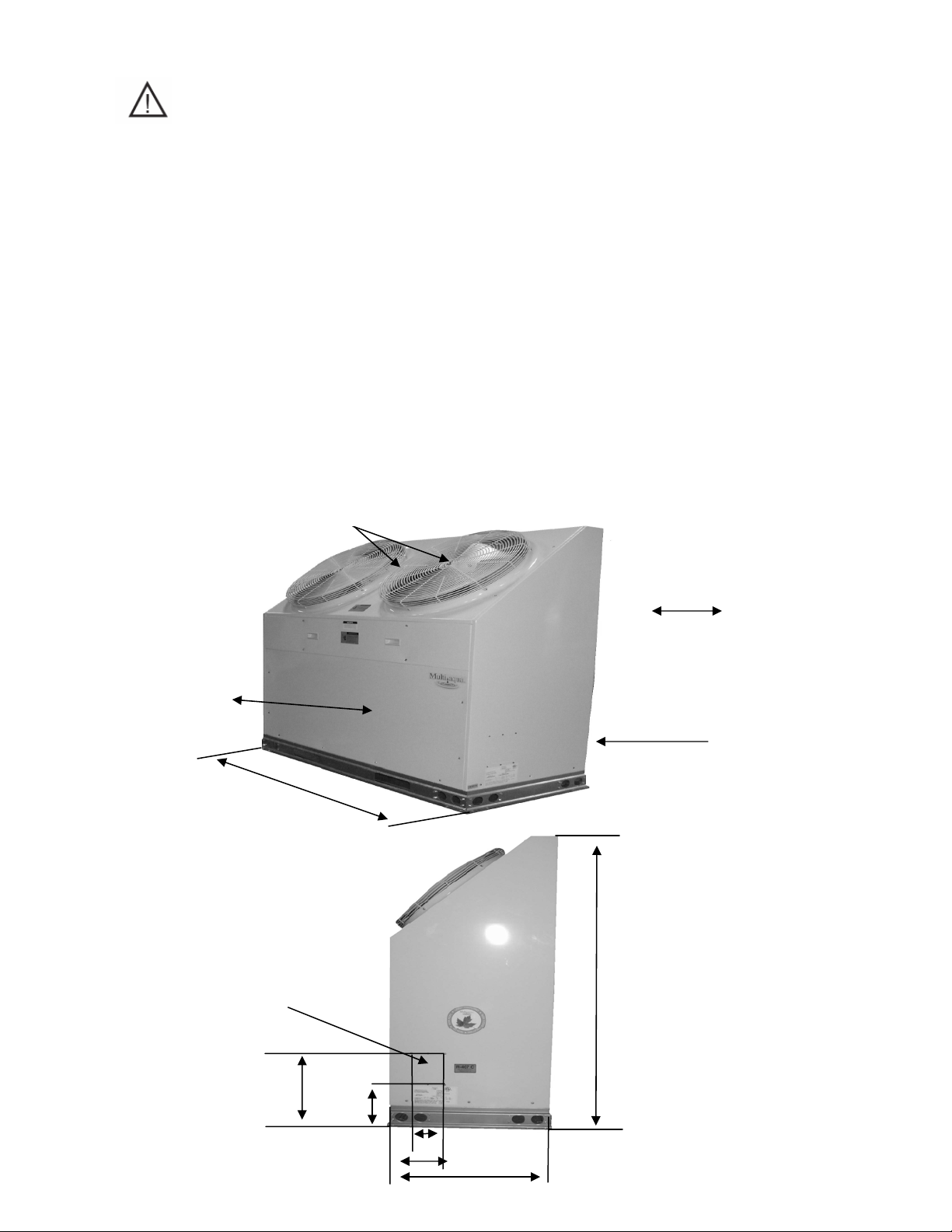
Consult local building codes or ordinances for special installation requirements. When
selecting a site to locate the chiller, consider the following:
• A minimum clearance of 60” on the service access front, 12” on the rear air inlet and a 60” fan discharge
clearance.
• The chiller can be located out or indoors. If installed indoors there must be 9000 cfm of outdoor air
changes circulated through the mechanical room to sufficiently operate the chiller. No ductwork can be
connected to the chiller’s condenser or condenser fans.
• If a concrete slab is used, do not connect the slab directly to any building’s foundation or structure to
prevent sound transmission.
• Locate the slab on a level surface that is above grade to prevent ground water from entering the chiller
cabinet.
Stated Service Clearances
60” Fan Discharge Clearance
60” Front Service
Clearance
Chiller Supply and Return
Piping Access
58.25
58.25”
60.00”
60.00”
12” Rear Clearance
0” Side Clearance
60.00”
15”
10”
13”
”
25.25”
22
Description of Electrical Controls
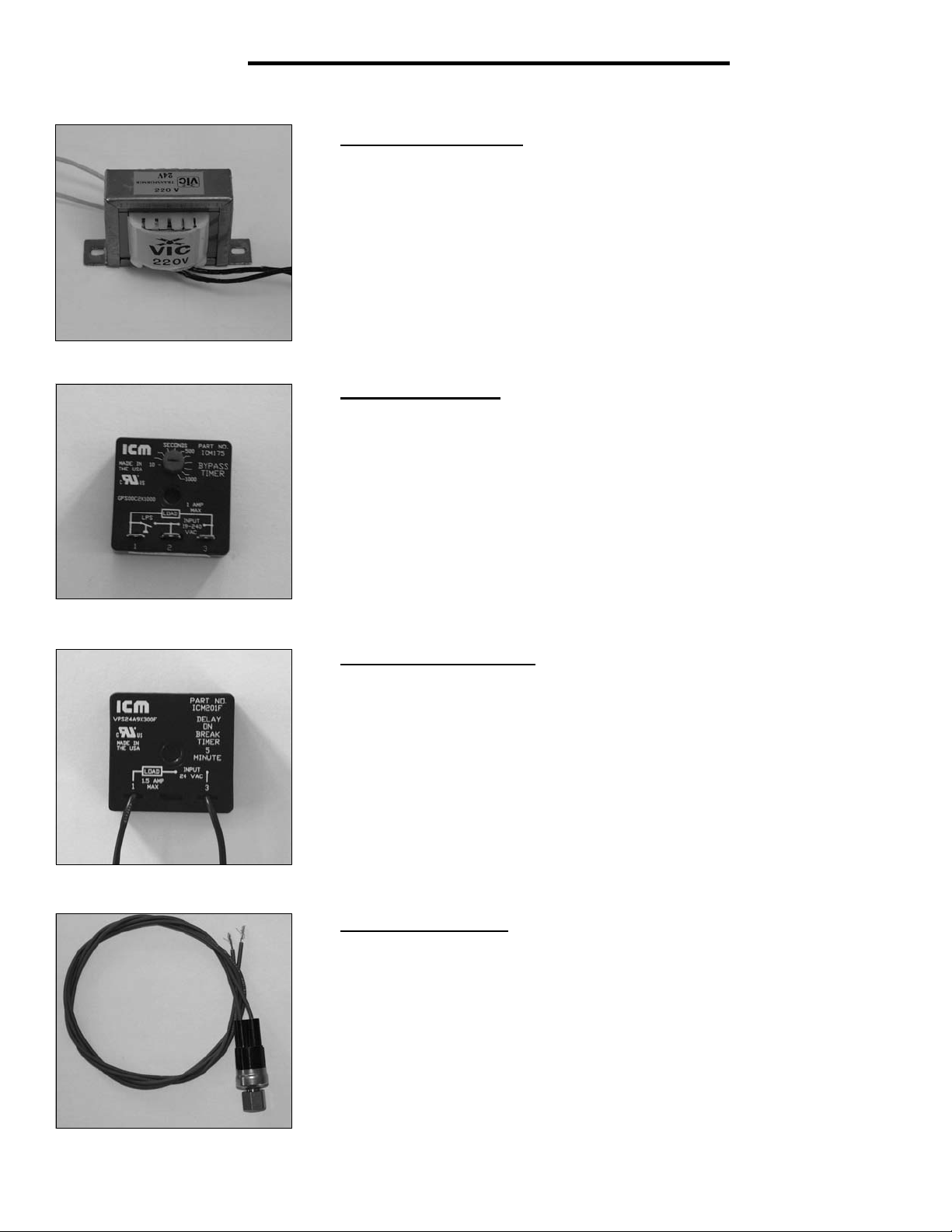
Control Transformer: The control transformer is rated at 24 vac, 40 va
(1.6 amps @ 24vac)
Pump Bypass Timer: The pump bypass timer is a 24 vac, 3-wire control.
When energized the timer will bypass the flow switch for 10 seconds (by
creating a circuit to the pump relay), energizing the pump relay, allowing the
pump to operate long enough to close the flow switch. In a normally operating
system the flow switch will stay closed powering the pump relay in series with
the low and high- pressure switches. Should the flow switch open, the timer
can only be reset by opening and closing the chiller's line voltage disconnect.
Refrigerant System Timer:
on break, 20wire timer. The normally closed contacts of the timer energize
the compressor contactor through the chilled solution control. When the chilled
solution control contacts open, the timer delays by opening its contact for 5minutes before resetting to the closed position.
High Pressure Switch: The high-pressure switch is an automatic reset control
that senses compressor discharge line pressure. It opens at 400 PSIG and
closes at 300 PSIG.
The refrigerant timer is a 24 vac, 5-minute delay
23
Description of Electrical Controls (continued)
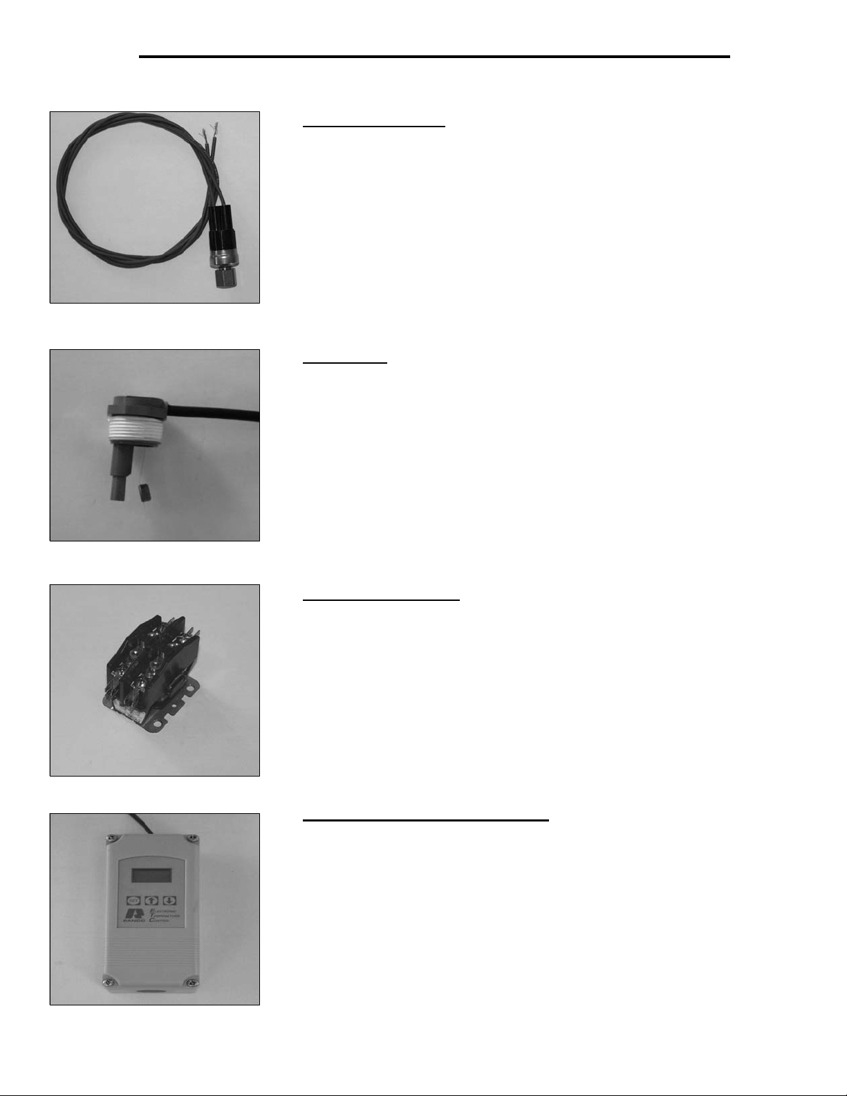
Low Pressure Switch:
that senses compressor suction line pressure. It opens at 40 PSIG and
closes at 80 PSIG.
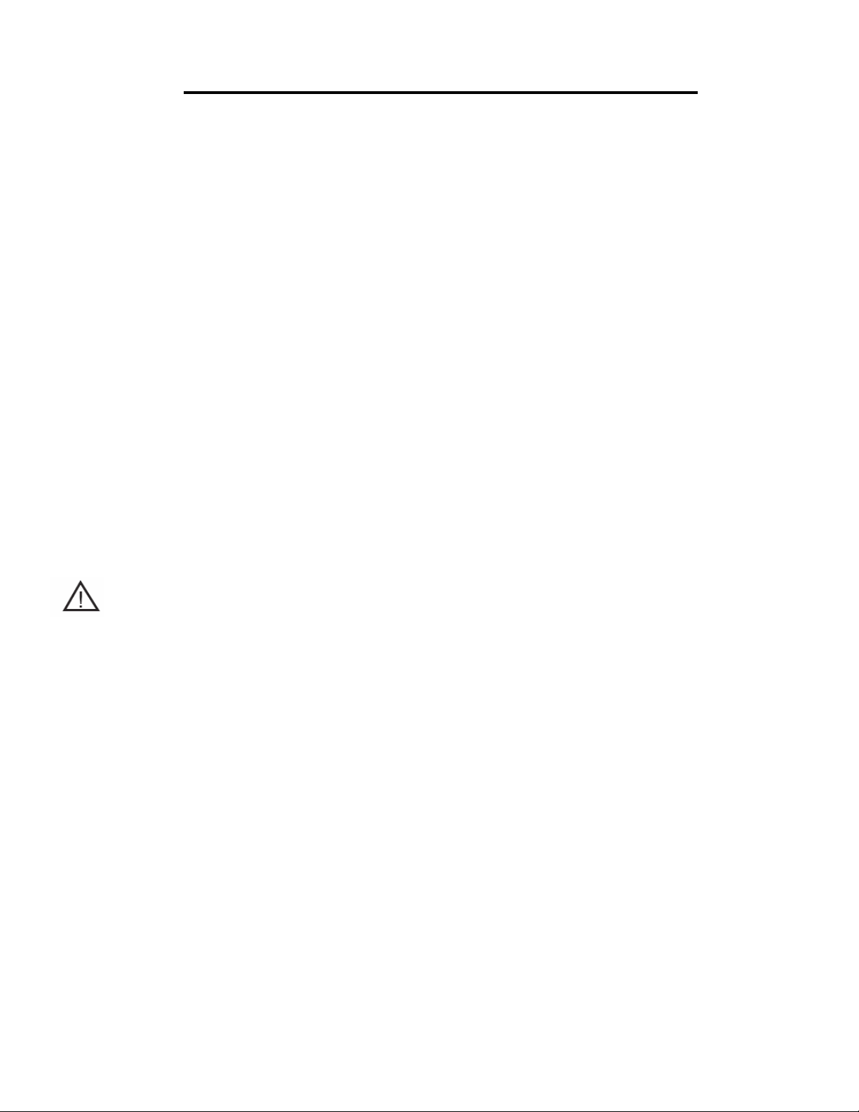
Flow Switch:
switch is inserted through a fitting into the pump discharge line. Liquid solution
flow deflects the paddle closing the switch. The flow switch is position sensitive.
The arrow ↑ on the switch must point in the direction of liquid solution flow.
The flow switch senses liquid solution flow. The paddle of the
The low-pressure switch is an automatic reset control
Compressor Contactor:
through the two or three normally open contacts. The contactor coil operates
(closes the contacts) when energized by 24 vac.
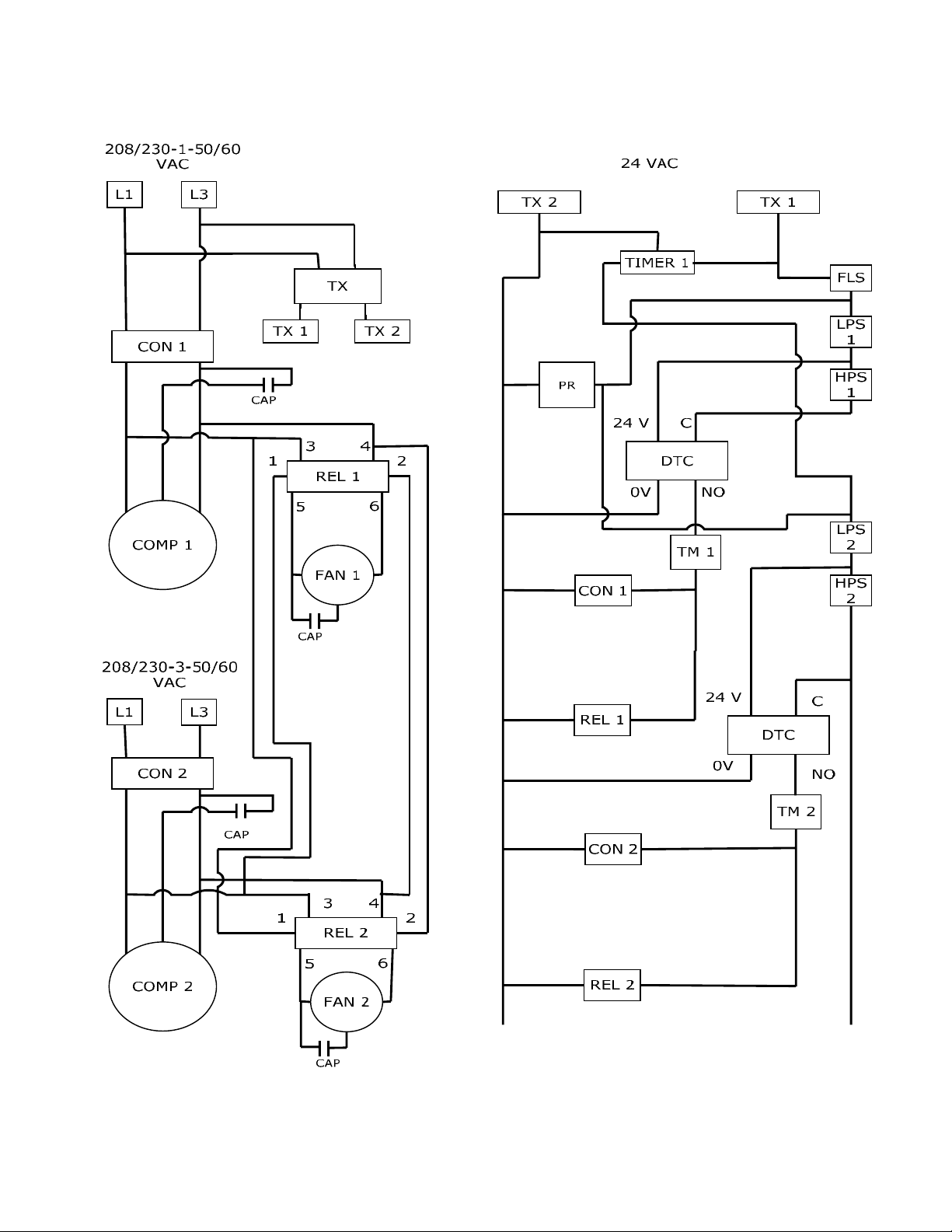
Liquid Solution Temperature Control:
is an adjustable microprocessor based temperature control. This control receives
temperature information from a thermistor located on the liquid solution supply
line. A liquid crystal display continually indicates liquid solution temperature. The
control is mounted inside the chiller cabinet.
The compressor contactor energizes the compressor
The liquid solution temperature control
24
Chiller Controls Sequence of Operation
When powered up, the Multiaqua chiller system energizes the control transformer creating 24 vac control voltage.
First the pump bypass timer is energized and temporarily bypasses the flow switch, energizing the pump relay. The
pump then starts to move liquid solution through the piping system (in a properly filled and air purged system). The
movement of liquid solution from the pump discharge keeps the flow switch closed. After a 10 second delay the pump
contact opens, connecting the flow switch in series with the high and low pressure switches. The pump will now run
continually unless the power supply is interrupted, or the flow switch opens.
If the liquid solution temperature controller is calling for cooling the control circuit is routed through the short cycle
timer and the three safety switches (the flow, high and low pressure switches) to the compressor contactor. This will
energize the compressor(s) and condenser fan motors. The liquid solution controller will open at the user programmed
set point, causing the refrigerant short cycle timer to open it's contact for 5 minutes as it delays before resetting to the
closed position. This will de-energize the compressor. Power fluctuations will also initiate a 5 minute time delay. The
5 minute delay allows the refrigerant system a period for pressure equalization, protecting the compressor(s) from
short cycling.
The chiller temperature controller utilizes a thermistor to monitor the liquid solution temperature change. The
temperature is then compared to the set point and differential temperatures programmed into the control by the user.
The set point is the liquid solution temperature which will cause the control switch to open. For example: The control
set point is programmed at 44°F LWT with a 10°F differential, which opens the controller at 44°F LWT and closes at
54°F. The differential temperature is the number of degrees above set point temperature programmed into the
controller. If liquid solution temperature falls to the set point, the controller cycles the compressors off.
Chillers are shipped with the control set point adjusted to 44°F LWT and a 10°F differential. Liquid solution
temperature set point should not be set below 35°F.
25

SYSTEM FAULTS:
Flow Switch Opening:
interrupted for any reason, the control will open shutting down and locking out the chiller operation. The only exception
to this is when power is first applied to the chiller and the pump bypass timer bypasses the flow switch for 10 seconds.
When the system is first filled with liquid solution and the pump is started, expect the system to cycle off
on the flow switch until all of the air is removed from the piping system. The system will have to be
reset by opening and then closing the disconnect switch or circuit breaker powering the chiller.
Low Pressure Switch Opening: Should the compressor suction pressure go low enough (40 PSI) to open the low-
pressure switch, the compressor and condenser fan motors will shut down. Check for a refrigerant leak, inoperative
thermal expansion valve, low liquid solution control setting, low ambient operation, low liquid solution flow, etc.
High Pressure Switch Opening: Should the compressor discharge pressure go high enough to open the high- pressure
switch the compressor and condenser fan motors will shut down. Check for a dirty condenser coil, inoperable fan motor(s)
or the recirculation of condenser air.
The flow switch is normally closed during pump operation. Should liquid solution flow be
Refrigeration System Operation
The refrigeration system is a closed loop consisting of 2 compressors, dual circuit heat exchanger (evaporator), metering
devices (TXVs) and condenser coil. The refrigerant circulated is R407c. Hot gas is pumped from the compressors to the
to the condenser coil where the two condenser fans pull cooler air across the coil condensing and sub cooling the refrigerant.
The now liquid refrigerant flows through the liquid line to the thermal expansion valves, where the refrigerant pressure
drops causing the refrigerant to boil at a much lower temperature (34-40°F). The refrigerant leaves the expansion valves and
swirls through the plates of the heat exchanger absorbing heat from the circulating liquid solution.
The evaporator or heat exchanger is designed to operate with an 8-10 °F superheat. The condenser is designed to
condense the refrigerant and sub cool it to 10 °F below condensing temperature.
Description Of Refrigerant Components
Scroll Compressor: All Multiaqua chillers feature Scroll compressors. Scroll
technology ensures reliable high performance at a low sound level over a wide range
of operating conditions.
Caution the top half of the scroll compressor operates at a temperature high
enough to cause serious injury.
26

Description Of Refrigerant Components (continued)
Brazed Plate Heat Exchanger: The "Heat Exchanger" or evaporator is of a
brazed copper and stainless steel design. Refrigerant and liquid solution is channeled
through narrow openings between plates and flows in opposite directions. The counter
flow design and fluid turbulence ensures maximum heat exchange at minimal pressure
drop.
Thermal Expansion Valve: Multiaqua chillers are equipped with Thermal Expansion
valves. The valves feature a liquid charged sensing bulb for consistent superheat at
various load conditions.
Condenser Coil: The air-cooled condenser coil is of copper tube with aluminum fin
construction. The coil is protected by a painted metal condenser grille.
27

Piping System Components
Supply Storage Tank: The supply storage tank must be used in the system with less
than 25 gallons of liquid solution. The tank prevents rapid cycling of the compressors
and acts as a reserve for chilled liquid solution.
Supply storage tank must be insulated in the field.
Part Number: WX202H (20 Gallon)
WX202H (42 Gallon)
Expansion Tank and Air Scoop: The Expansion Tank and Air Scoop assembly is
used to compensate for the expansion and contraction of liquid in the system. The
air scoop eliminates air entrance in the liquid solution.
Part Number: 1500/1"
Liquid Solution Bypass Valve: The liquid solution bypass valve relieves system
pressure from the liquid solution supply to the return as system air handler control
are cycled off.
Part Number: D146M1032- 3/4"
D146M1040- 1 1/4"
Motorized Valve: The air handler motorized valve controls the flow of liquid solution
to the systems air handlers. Each air handler in the system should have a motorized
or solenoid valve.
Part Number: MZV524E-T 1/2" 2-Way Zone Valve
MZV525E-T 3/4" 2-Way Zone Valve
MZV526E-T 1" 2-Way Zone Valve
VT3212G13A020 1/2" 3-Way Zone Valve
VT3212G13A020 3/4" 3-Way Zone Valve
28

Composite Piping Layout and Design
Understanding the function and friction loss of each part of the piping system is important to the layout and successful
installation of a chilled liquid solution system.
2-Way Liquid Solution Control Valves
1-
Bypass Valve
2-
Storage Tank
3-
Expansion Tank
4-
Coil
5-
Chiller
6-
Pump
7-
The circulation pump is the key performer in the piping system. The pump must circulate the liquid solution through the
heat exchanger and piping system to the air handlers. Pumps are designed to deliver a flow rate measured in gallons
per minute(GPM). The pump must be able to overcome the resistance to flow (pressure drop) imposed by the chiller
components, piping system and air handlers while maintain the necessary flow rates in gallons per minute. Pump
capacities in gallons per minute and pressure drop (feet of head) are listed in table 1.
An adjustable valve must be used to throttle the discharge liquid solution flow rate to appropriate levels based
on capacity and glycol mix percentages.
Chiller System Data
Table 1
GPM
GPM
MAC-120
18
28.8
50
3% of Total
1.85
1.5
MAC Series
Min. Liquid Solution Flow Rate
Max.Liquid Flow Rate
Min. Liquid Solution Content in System
Expansion Tank Size
Internal Chiller Pressure Loss
Chiller Liquid Solution Content
Piping resistance or pressure drop is measured in feet of head. A foot of head is the amount of pressure drop imposed
in lifting liquid solution one foot. Pumps in the Multiaqua system are designed to move rated liquid solution flow (see
table 1) in GPMs.
Gallons
Gallons
Ft.of Head
Gallons
29

Banked Chiller Configuration
Notes:
Installing Multiaqua chillers in parallel is recommended.
30

n
Installation Notes:
Piping such as PEX,steel, copper or PVC can be used with the Multiaqua system. Check local building codes for
material conformation. Care must be taken when using PVC as the presence of propylene glycol may destroy
plastics. Pressure drop data for the selected piping material is readily available and should be used. Should the
Multiaqua chiller be installed using existing steel (ferrous metal) piping system, dielectric fittings must be used
at the chiller and air handler. The factory supplied wye strainer will capture particles of rust and sediment
inherent with steel piping and should be checked and cleaned after initial start up and open a regular maintenance
during the life of the system.
Any piping used to conduct liquid solution must be insulated in accordance with local and national mechanical
codes. Information on insulation installation and application can be obtained from Armaflex web site at
www.armaflex.com
of the chiller and air handlers, it is suggested that shutoff valves be installed at the chiller and air handler(s). If
ball valves are used, they can double as balancing valve(s) in the supply piping at each air handler. Chiller
shutoff valves should be attached at the chiller connections with unions.
The air handlers are to be controlled with electrically operated "slow-opening" solenoid valves, circulators or
motorized zone valves as manufactured by Erie controls (www.eriecontrols.com/products/index.htm
thermostat or air handler installed digital control operate the valves.
and Owens-Corning site at www.owenscorning.com/mechanical/pipe/. For future servicing
) A remote
Bypass valves as shown in drawing 1, should be installed between the supply and the return chilled liquid
solution supply pipes at a convenient location to the installation. The bypass valve operates to bypass liquid solutio
between the supply and return chilled liquid solution lines. In the event air handlers valves should shut down, the
bypass valve is set to open up and bypass liquid solution between the supply and return lines, relieving pressure
and eliminating the possibility of pump cavitations. To adjust the valve, run the system with one air handler
solenoid actuated. De-energize the solenoid valve, (at this point no liquid solution will be flowing through the air
handlers.) and adjust the bypass valve to relieve pressure between the supply and return piping.
Bleed ports will be factory installed on all Multiaqua air handlers. Bleed ports are opened to eliminate air trapped
in the air handlers after filling the system with liquid solution and Propylene Glycol and before operating the
refrigerant compressor in the chiller.
The minimum liquid solution content in the chiller system,(piping, chiller, and air handlers), is 50 U.S. gallons.
Estimate the system liquid solution content. Should the system have less than 50 gallons of liquid solution
content, a chilled liquid solution storage tank must be installed. The tank stores enough chilled liquid solution
to prevent frequent chiller compressor cycles at light load and prevents chilled liquid temperature swings at
higher load conditions when the chiller compressor is waiting to cycle on the time delay control.
Propylene Glycol must be added to the water used in the system
low ambient temperature conditions and low chilled liquid solution temperatures. In comparison to water,
Propylene Glycol slightly lessons the temperature exchange in the chiller heat exchanger. However, that is
offset by the increased flow of liquid solution through the piping system enabled by the Propylene Glycol. To
determine the Propylene Glycol content for various ambient temperatures refer to table 6 page 32.
. Propylene helps prevent freeze-ups due to
In no instance should a Multiaqua chiller be installed with less than 10% Propylene Glycol content in the piping
system. Using less than the recommended Propylene Glycol percentage content voids equipment warranty.
31

Polypropylene Glycol System Content vs.
Minimum Ambient Temperature
To not engage in cold ambient mitigation will result in the failure of components, property damage and
void warranty.
Table 6
Percent of Propylene Glycol to Water Content
Propylene Water
Glycol % Flow
10% x 1.020
20% x 1.028
30% x 1.036
40% x 1.048
50% x 1.057
Ethylene Glycol is environmentally hazardous and not recommended. Inhibited Propylene Glycol ( typical
automotive coolant) is not to be used in a Multiaqua Chiller under any circumstances.
family of Glycol-based coolants of food grade Propylene Glycol is suggested. Information on Ambitrol is available
from Dow at www.dow.com,
Capacity
x .99
x .98
x .98
x .97
x .96
search word "Ambitrol".
Min. Ambient
Temperature
26°F
18°F
8°F
-7°F
-29°F
GPM Adjustment
= 100 % Capacity
x 1.01
x 1.03
x 1.07
x 1.11
x 1.16
Dow Chemical's "Ambitrol"
Expansion Tanks:
Liquid solution expansion and contraction within the closed system must be compensated for with an expansion
tank. The expansion tank used with the Multiaqua system, is a steel tank with a rubber bladder attached to it
internally. There is air pressure on one side of the rubber bladder that keeps the bladder pushed against the
sides of the tank before the system is filled with liquid solution (illustration above). As the liquid solution heats
up the bladder will be pushed further away from the tank walls, allowing for expansion and contracting as the
liquid solution temperature changes. By flexing, the bladder controls the system pressure adjusting to
temperature variations of the chilled liquid solution system.
It is critical that the expansion tank's air bladders pressure be less than the system solution pressure. Air
pressure can be measured with an automotive tire gauge at the bicycle valve port on the expansion tank. Bleeding
air out of the bladder or increasing the pressure with a bicycle pump will adjust pressure.
System must use a liquid solution storage tank if system volume is less than 50 U.S. gallons.
32

Filling System with Liquid Solution and Coolant
(Propylene Glycol)
Before filling system with Propylene Glycol and water, pressure test the piping system with compressed air.
Testing should be done at a maximum of 50 psi.The system should hold air pressure for a minimum of
one hour with no leakage.
Concentrations of Propylene Glycol in excess of 50% will destroy o-rings in fittings and pump. Water should
be added to the system first or a liquid solution diluted Propylene Glycol mix.
System that contains 50 or more U.S. gallons should have a tee fitting with a stopcock installed in the return
line close to the chiller. The stopcock can be opened and attached to a hose with a female X female hose
fitting. In the open end of the hose section (1 -1.5 feet long) insert a funnel and pour into the system the
diluted Propylene Glycol/liquid solution mixture or add water first and then the quantity of Propylene Glycol
needed for minimum ambient protection (refer to Table 6). After adding the Propylene Glycol/water mixture, or
liquid solution and then coolant proceed to add enough water to the system to achieve a 15 psi gauge pressure.
To measure system pressure shut off the stopcock, remove hose and attach a water pressure gauge. Open
the stopcock to read system pressure.
Systems that use the Chilled Liquid Solution Storage Tank should be filled at the tee/stopcock fitting in the
outlet fitting of the storage tank. Fill the tanks with 10 gallons of water and with a funnel pour the calculated
(refer to Table 6) amount of Propylene Glycol into the tank. The amount of Propylene Glycol added should be
calculated to achieve minimum ambient protection. After adding Propylene Glycol, fill the system with enough
liquid solution to bring system pressure to approximately 15 psi gauge pressure. To measure system pressure
shut off the stopcock and attach a water pressure gauge. Open the stopcock to read system pressure.
Air Elimination
Since we have the system filled we must eliminate the air left in the system. Briefly open each bleed valve at
the air handlers and allow trapped air to escape. This will eliminate much of the air left in the system.
Next we will start the pump and continue bleeding air from the system. Be sure the chiller has line voltage
available to it and set the chilled liquid solution control up to 100 °F, which will ensure that only the pump runs
at this point. The pump should now start and remain running. Should the pump stop at any time during this
process it is an indication that the flow switch had air move across it allowing the circuit to be interrupted.
Continue to bleed some air out of the system at the highest locations before resetting the pump bypass timer
to get the pump running again. Open and close the power supply switch to the chiller to restart the pump.
Continue bleeding air with the pump operating. You may have to start and re-start the pump a few times to
complete air removal.
If you continue having air entrapment issues, it will be necessary to install a micro bubble remover device.
All piping systems should have a minimum of 10% Propylene Glycol in the system even in climates with nonfreezing ambient temperatures.
Using less than the recommended Propylene Glycol percentage content voids equipment warranty.
Liquid solution control valves (solenoid or motorized valves) should be selected for low pressure drop. If a selected
valve contributes to pushing your total head calculation to more than 50 feet of head, a larger valve may be
needed to bring your total head below the maximum of 50 feet.
Liquid Solution Balancing:
Liquid solution balancing will require an accurate digital thermometer to measure return line liquid solution
temperature at each air handler. Set the chilled liquid solution temperature control in the chiller at a normal
operational temperature (44°F) and measure pump discharge temperature with the digital thermometer to check
system solution temperature. After the chilled liquid solution temperature has lowered to the set point begin the
balancing process. The system must be free of air and each air handler set at a temperature low enough to
continue cooling operation (and liquid solution flow) during the balancing process. Begin by measuring the return
line chilled liquid solution temperature of each air handler. Begin incrementally closing the supply line balance
valve at the air handlers with the lowest return line chilled liquid solution temperature. Continue this process
until each air handler has close to the same return line chilled liquid solution temperature.
33

MAC120-3 Ladder Wiring Diagram
380/460-3-50/60
34

MULTIAQUA
380/460-3-50/60
BK
L1
RD
L2
WH
L3
GND
BK
WH
NOTE 1
DTC 1 DTC 2
BL
WH BK
MAC120-3 Wiring Diagram
380/460-3-50/60
BL
BK
BK
T1
RD
CON1`
BKBK
CON2
REL 2REL 1
BL
NONO C C
COM24 vac COM 24 vac
WH
COMP
T2
WH
T3
BK
T1
RD
COMP
T2
WH
T3
BK
BLBL
BK
BK
1
2
FC1
BK
RD
WH
FAN
TRANSFORMER
380/460-3
24 vac
BKBLBK
1
YL
YL
BL
FC2
FAN
RD
FS
BK
BL
BL
1
2
3
BK
4
BK
BK
1
2
3
4
2
LPS1
HPS1
TIMER1
BK
BK
2
TM2
BK
1
BL
LPS2
BK BK
HPS2
BK
2
TM2
BK
1
BKBK
BL
TITLE
AUTHOR
DATE
REVISION
MAC120-03 380/460-3-50/60
kjg
09/22/08
0807300029 REV 1
LEGEND:
FACTORY WIRING
FIELD WIRIN G
DIGITAL T EMPERA TURE CONT ROLLER
DTC
FC
CONDENSER FAN CONTACTOR
REL
CONDENSER FAN RELAY
35
COMPRESSOR CONTACTOR
CON
FLOW SWITCH
FS
LOW PRESSURE SWITCH
LPS
HIGH PRESSURE SWITCH
HPS
TIMER
PUMP BYPASS TIMER
TM2
REFRIG ERANT SYS TEM TIME R
NOTES:
1.PUMP STARTER RELAY

MAC120-3-L with Low Ambient Kit Wiring Diagram
MULTIAQUA
380/460-3-50/60
BK
L1
RD
L2
WH
L3
GND
BK
NOTE 1
FAN CYCLE
PRESSURE
SWITCH
FAN CYCLE
PRESSURE
SWITCH
DTC 1 DTC 2
REL 1
CON1`
CON2
BKBK
REL 2
NONO C C
COM24 vac CO M 24 vac
380/460/-3-50/60
BL
BK
T1
RD
COMP
T2
WH
BK
RD
WH
BK
1
T3
T1
COMP
T2
2
T3
BLBL
BK
BK
FC1
NOTE 2
FAN
TRANSFORMER
380/460-3
24 vac
BKBL
1
31
FC2
YL
YL
BL
1
2
3
4
BK
FAN
2
1 3
4
64 6
NOTE 3
RD
BK
BK
BK
BK
BK
1
2
3
4
BK
BK
FS
BK
BL
BL
LPS1
HPS1
TIMER1
BKBK
2
TM2
1
BL
LPS2
BK BK
HPS2
2
TM2
1
BL
TITLE
AUTHOR
DATE
REVISION
MAC120-03 WITH LOW AMBIENT KIT
kjg
09/22/08
0608400097 REV 1
LEGEND:
FACTORY W IR IN G
FIELD WIRING
DIGITAL TEMPE R ATU R E C ON TR O LLER
DTC
FC
CONDENSER FAN CONTACTOR
REL
CONDENSER FAN RELAY
36
COMPRESSOR CONTACTOR
CON
FLOW S WITCH
FS
LOW PRESSURE SWITCH
LPS
HIGH P R E SSURE SWITCH
HPS
TIMER
PUMP BYPASS TIMER
TM2
REFRIGERANT SYSTEM TIMER
NOTES:
1. PUMP ST A R TE R RELAY
2. LOW AMB IE NT R E LAY #1
3. LOW AMBIE NT RE LAY #2

MAC120-2 Ladder Wiring Diagram
208/230-3-50/60
37

MAC120-2 Wiring Diagram
208/230-3-50/60
38

MAC120-2-L with Low Ambient Kit Wiring Diagram
208/230-3-50/60
39
MAC120-1 Ladder Wiring Diagram
208/230-1-50/60
40

MAC120-1 Wiring Diagram
208/230-1-50/60
41

MAC120-1-L with Low Ambient Kit Wiring Diagram
208/230-1-50/60
42

MAC120 CERTIFIED DRAWING
43

MAC036,048 & 060 Air-Cooled Chiller
Air-Cooled Chillers for Global Residential
and Light Commercial MicroClimates
44

MAC036,048 & 060 NOMENCLATURE BREAKDOWN
MACXXX - XX - X
Accessory
Air-Cooled Chiller
036= 36,0000 BTUH
048= 48,0000 BTUH
060= 60,0000 BTUH
Voltage
01 = 208/230-1-50/60
02 = 208/230-3-50/60
03 = 380/460-3-50/60
Options
N= No Options
L= Low Ambient Kit
Available Model Numbers
MAC036-01-N MAC048-01-N
MAC036-01-L
MAC036-02-N
MAC036-02-L
MAC048-01-L
MAC048-02-N
MAC048-02-L
MAC060-01-N
MAC060-01-L
MAC060-02-N
MAC060-02-L
MAC060-03-N
MAC060-03-L
45

HVAC Guide Specifications
Air-Cooled Liquid Chiller
Nominal Size:
3, 4 & 5 Tons
Multiaqua Model Number:
MAC036-01-N-407, MAC036-01-L-407: MAC036-02-N-407, MAC036-02-L-407,
MAC048-01-N-407, MAC048-01-L-407: MAC048-02-N-407, MAC048-02-L-407,
MAC060-01-N-407, MAC060-01-L-407, MAC060-02-N-407, MAC060-02-L-407,
Part 1-General
1.01 System Description
Multiaqua air-cooled liquid chillers are designed using scroll compressors, low sound condenser fans and high
efficiency pumps.
1.02 Quality Assurance
A. Certified in accordance with U.L. Standard 95, latest version (U.S.A.)
B. Construction shall comply with ASHRAE 15 Safety Code, NEC and ASME applicable codes. (U.S.A.
Codes)
C. Manufactured in a facility registered to ISO 9002, Manufacturing Quality Standard.
D. ETL Certified
E. Fully load tested at the factory.
F. Damage resistant packaging.
1.03 Delivery, Storage and Handling
A. Packaged and readied for shipment from the factory.
B. Controls shall be capable of withstanding 150°F storage temperatures in the control compartment.
C. Stored and handled per manufacturer’s rec o mmendations.
Part 2-Product
2.01 Equipment
A. General:
1. Unit shall be a factory assembled and tested air-cooled liquid chiller.
2. Shall be assembled on heavy gauge steel mounting/lifting rails.
3. Contained within the unit cabinet shall be all factory wiring, piping, controls, refrigerant charge
(R407c), POE oil and special accessories required prior to start up.
4. Brass body strainer with 20 mesh screen and blow down shall be supplied in cabinet as a
field installable accessory.
B. Unit Cabinet:
1. Composed of heavy gauge galvanized steel casing with a baked polyester powder.
2. Capable of withstanding 500-hour salt spray test in accordance with the ASTM (USA) standard.
C. Condenser Fans:
1. 4-blade, aluminum construction and shall be dynamically balanced and corrosion resistant.
2. Horizontal discharged air.
3. Motors and blades shall be protected by coated steel wire safety guards.
D. Fan Motors:
1. Condenser fan motors shall be single speed, direct drive.
2. Totally enclosed.
3. Permanently lubricated sleeve bearings and Class F insulation.
4.
Internal overload protection.
E. Compressors:
1. Unit shall contain one fully hermetic scroll compressors.
2. Direct-drive, 3500 rpm (60Hz)
3. Compressor motor shall be suction gas cooled.
4. Internal motor protection.
5. Externally protected by low and high pressure cutout devices.
6. Individual vibration isolators .
46

F. Pump:
1. Circulating pump shall be stainless steel with high efficiency enclosed motor.
2. Unit shall have chilled liquid solution piping to the exterior of the cabinet.
G. Evaporator:
1. Evaporator shall have one independent refrigerant circuit and one liquid solution circuit.
2. Rated for a refrigerant side working pressure of 450 psig and a maximum water side working
pressure of 150 psig.
3. Single pass, ANSI type 316 stainless steel, brazed plate construction.
4. Externally insulated with closed cell, elastomeric foam. (ASTM518)
H. Condenser:
1. Condenser coil shall be air-cooled with integral subcooler.
2. One independent refrigerant circuit.
3. Constructed of rifled copper tubing mechanically bonded to aluminum fins.
4. Cleaned and dehydrated.
5. Factory leak tested to 450 psig.
I. Refrigerant Circuits:
1. Each circuit shall contain a sight glass, liquid line filter, thermal expansion valve,
refrigerant charge of R407c and POE compressor oil.
Part 3-Controls and Safeties
3.01 Controls
A. Chiller shall be completely factory wired and tested.
B. Capacity control shall be based on leaving chilled liquid solution temperature.
1. Temperature accuracy shall be + - 1.0°F.
2. Controls shall be capable of staging the two compressors.
C. Controls shall include the following components.
1. 24vac transformer to serve all controllers relays and control components.
2. Microprocessor based liquid solution temperature controller.
3. Leaving water temperature thermistor.
4. Pump bypass timer.
5. Compressor recycle timer.
6. Optional low pressure bypass timer for low ambient operation.
7. Optional fan cycling control for low ambient operation.
8. Chilled liquid solution flow switch.
3
.02 Safeties
A. Unit shall be equipped with thermistors and all necessary components in conjunction with the
control system to provide the following protectants.
1. Low refrigerant pressure.
2. High refrigerant pressure.
3. Low chilled liquid solution temperature.
4. Low chilled liquid solution flow.
5. Thermal overload.
6. Short cycling.
Part 4-Operating Characteristics:
4.01 Temperatures
A. Unit shall be capable of starting and running at outdoor temperatures from 55°F to 120°F.
B. Optional Low Ambient Kit shall allow starting and running at outdoor temperatures to -20°F. A
field supplied and installed crankcase heater must be used when operating at these temperatures.
C. Unit shall be capable of starting up with a maximum 80°F and a sustained 70°F entering fluid
solution temperature to the evaporator.
D. Minimum 10% Glycol solution is required. For outdoor temperatures below 32°F, reference
MAC Glycol Solution Data table.
4.02 Electrical Requirements
A. Primary electrical power supply shall enter the unit at a single location.
B. Electrical power supply shall be rated to withstand 120°F operating ambient temperature.
C. Units shall be available in 1 or 3-phase power at the voltages show
n in the equipment electrical data.
D. Control points shall be accessed through terminal block.
47

g
MAC036, 048 & 060 Product Specifications
Physical Data
Coil Chiller Weight (lbs)
Model
Number
MAC036 38 48 3/8 1 49.75 39.75 16.25 84.66 oz 280 283
MAC048 38 48 3/8 2 49.75 39.75 16.25 92.95 oz 292 295
MAC060 38 48 3/8 2 49.75 39.75 16.25 92.95 oz 313 316
Model Number
MAC036-01 208/230-1-50/60 18.4 95 1.05 1050 3.70 3450 28.80 45
MAC036-02 208/230-3-50/60 11.4 77 1.05 1050 3.70 3450 20.05 30
MAC048-01 208/230-1-50/60 22.1 137 1.05 1050 3.70 3450 33.43 50
MAC048-02 208/230-3-50/60 16.4 91 1.05 1050 3.70 3450 26.30 40
MAC060-01 208/230-1-50/60 32.1 169 1.05 1050 3.70 3450 45.93 70
MAC060-02 208/230-3-50/60 19.3 137 1.05 1050 3.70 3450 29.93 45
MAC060-03 380/460-3-50/60 10 75 0.60 1050 2.85 3500 16.55 25
Height
(in)
Length
(in)
Volts/ Phase/
Hertz
Copper
Diameter
(in)
Coil
Rows
Height
(in)
Length
(in)
Electrical Data
Condenser
Compressor
(RLA) (LRA) (FLA) (RPM) (FLA) (RPM)
Fan Motor
(2 qty)
Pump Motor
Width
(in)
Refrigerant
R407c
Fuse or HACR Circuit
Breaker Per Circuit
Minimum Amps
Net Shipping
Maximum
Amps
Compressor
Refrigerant R407c R407c R407c
Heat Exchanger Brazed Plate Brazed Plate Brazed Plate
Max. Head Pressure 50 ft. 50 ft. 50 ft.
Max Flow Rate 8.6 gpm 11.5 gpm 14.4 gpm
Min Flow Rate 5.5 gpm 6.5 gpm 9.0 gpm
Supply Water Temp 44° 44° 44°
Return Water Temp 54° 54° 54°
Min. Solution Content 25 Gallons 25 Gallons 25 Gallo ns
Expansion Tank Size 2 Gallons 2 Gallons 2 Gallons
Pump 0.5 HP 0.5 HP 0.5 HP
Water Connections 1" S & 1.25" R 1" S & 1.25" R 1" S & 1.25" R
Internal Pressure loss 1.77 ft of head 1.68 ft of head 1.85 ft of head
Multiaqua chillers are designed to operate exclusively with R407c refrigerant in a self-contain ed, pre-charged refrigerant system. Do not
access the closed refrigerant circuit for any reason other than after-sale, after installation component replacement. Routine maintenance
and service is to be performed by qualified personnel only.
MAC036 MAC048 MAC060
Copeland
Scroll
Copeland
Scroll
These specifications are subject to change without notice.
Copeland
Scroll
Copper Wire Size (1% Voltage Drop)
200 6 4 4 4 3 3 2 2
150 8 6 6 4 4 4 3 3
100 10 8 8 6 6 6 4 4
th in Feet
50 14 12 10 10 8 8 6 6
15 20 25 30 35 40 45 50
Supply Wire
Len
Supply Circuit Ampacity
48

MAC036, 048 & 060 Product Specifications
MAC036, 048 & 060 Capacity / Watts / EER
MAC036 MAC048 MAC060
O/A Temp (°F)
82 2.9 3.3 10.55 3.9 4.3 10.88 5.1 5.3 11.55
95 2.8 3.7 9.08 3.7 4.6 9.65 4.9 5.9 9.97
100 2.7 3.9 8.31 3.6 4.8 9.00 4.8 6.1 9.44
105 2.7 4.0 8.10 3.5 5.0 8.40 4.7 6.4 8.81
110 2.6 4.3 7.28 3.4 5.4 7.56 4.7 6.5 8.68
Propylene Glycol %
10%
20%
30%
40%
50%
Example: 30% glycol solution.
Maximum Flow Rate = 12gpm x 1.036
System capacity x .98
Use Propylene Glycol Only
Important
If the outside temperature is expected to fall below freezing (32°F) in the area the Multiaqua chiller is to be
installed; the installer must take the following precautions. Failure to do so will void the warranty.
To not engage in cold ambient mitigation will result in the failure of components such as the heat
exchanger, piping, circulating pump, etc… and or property damage.
• Keep the liquid solution at a minimum of ten percent propylene glycol even in areas where there is no danger
of freezing.
• The percentage amount of glycol recommended is dependent on the expected ambient temperatures and the
solution makeup recommendation of the glycol manufacturer. Refer to the Glycol Solution Data table above.
• Ensure the system circulating pump is in a constant energized mode to keep a continuous circulation of liquid
solution.
The Multiaqua chiller is a self-contained air-cooled condenser, coupled with an insulated brazed plate heat
exchanger (evaporator). The system utilizes a scroll compressor to circulate refrigerant between the condenser
and heat exchanger. The refrigerant is metered into the heat exchanger with a thermostatic expansion valve.
Protecting the system are high and low pressure switches as well as a pump flow switch.
Liquid solution (water and propylene glycol; minimum 10 % is required) is circulated through the heat
exchanger by an externally mounted pump. The liquid solution flows through the heat exchanger to the system
supply piping and on to the air handlers.
Low ambient kits are available for operating ambient temperatures down to 0 degrees Fahrenheit. The low
ambient kits consist of an ICM 325 (+) ICM (175) for single and three phase 208/230 vac chillers. For the three
phase 380/460 vac chillers a pressure activated fan control is used.
Tons KW EER Tons KW EER Tons KW EER
Glycol Solution Data
Water
Flow Capacity
x 1.020
x 1.028
x 1.036
x 1.048
x 1.057
x 0.99 26°F x 1.01
x 0.98 18°F x 1.03
x 0.98 8°F x 1.07
x 0.97 -7°F x 1.11
x 0.96 -29°F x 1.16
These specifications are subject to change without notice.
Min. Ambient Temp GPM Adjustment= 100% Capacity
49

MAC036 Cooling Performance Data
MAC036 CAPACITIES with 0% Glycol
LWT (°F)
35 1.70 1.60 1.50 1.40 1.30
40 2.30 2.20 2.10 2.10 2.00
42 2.60 2.50 2.40 2.40 2.30
44 2.90 2.80 2.70 2.70 2.60
45 3.10 3.00 2.90 2.80 2.70
46 3.20 3.10 3.00 3.00 2.90
48 3.60 3.50 3.20 3.30 3.20
50 3.90 3.80 3.50 3.60 3.50
55 4.80 4.70 4.30 4.30 4.20
60 5.80 5.60 5.20 5.20 5.00
82 95 100 105 110
TONS GPM TONS GPM TONS GPM TONS GPM TONS GPM
MAC036 CAPACITIES with 10% Glycol
LWT (°F)
35 1.68 1.58 1.49 1.39 1.29
40 2.28 2.18 2.08 2.08 1.98
42 2.57 2.48 2.38 2.38 2.28
44 2.87 2.77 2.67 2.67 2.57
45 3.07 2.97 2.87 2.77 2.67
46 3.17 3.07 2.97 2.97 2.87
48 3.56 3.47 3.17 3.27 3.17
50 3.86 3.76 3.47 3.56 3.47
55 4.75 4.65 4.26 4.26 4.16
60 5.74 5.54 5.15 5.15 4.95
82 95
TONS GPM TONS GPM TONS GPM TONS GPM TONS GPM
ENTERING AIR TEMPERATURE (°F)
7.2 7.2
ENTERING AIR TEMPERATURE (°F)
7.2 7.2
7.2 7.2 7.2
7.2
100 105
7.2
7.2
110
MAC036 CAPACITIES with 20% Glycol
LWT (°F)
35 1.67 1.57 1.47 1.37 1.27
40 2.25 2.16 2.06 2.06 1.96
42 2.55 2.45 2.35 2.35 2.25
44 2.84 2.74 2.65 2.65 2.55
45 3.04 2.94 2.84 2.74 2.65
46 3.14 3.04 2.94 2.94 2.84
48 3.53 3.43 3.14 3.23 3.14
50 3.82 3.72 3.43 3.53 3.43
55 4.70 4.61 4.21 4.21 4.12
60 5.68 5.49 5.10 5.10 4.90
82 95 100 105 110
TONS GPM TONS GPM TONS GPM TONS GPM TONS GPM
ENTERING AIR TEMPERATURE (°F)
7.2
These specifications are subject to change without notice.
7.2 7.27.2 7.2
50

MAC036 Cooling Performance Data
MAC036 CAPACITIES with 30% Glycol
LWT (°F)
35 1.67 1.57 1.47 1.37 1.27
40 2.25 2.16 2.06 2.06 1.96
42 2.55 2.45 2.35 2.35 2.25
44 2.84 2.74 2.65 2.65 2.55
45 3.04 2.94 2.84 2.74 2.65
46 3.14 3.04 2.94 2.94 2.84
48 3.53 3.43 3.14 3.23 3.14
50 3.82 3.72 3.43 3.53 3.43
55 4.70 4.61 4.21 4.21 4.12
60 5.68 5.49 5.10 5.10 4.90
82 95 100 105 110
TONS GPM TONS GPM TONS GPM TONS GPM TONS GPM
7.2 7.2 7.2 7.2
MAC036 CAPACITIES with 40% Glycol
LWT (°F)
35 1.65 1.55 1.46 1.36 1.26
40 2.23 2.13 2.04 2.04 1.94
42 2.52 2.43 2.33 2.33 2.23
44 2.81 2.72 2.62 2.62 2.52
45 3.01 2.91 2.81 2.72 2.62
46 3.10 3.01 2.91 2.91 2.81
48 3.49 3.40 3.10 3.20 3.10
50 3.78 3.69 3.40 3.49 3.40
55 4.66 4.56 4.17 4.17 4.07
60 5.63 5.43 5.04 5.04 4.85
82 95 100
TONS GPM TONS GPM TONS GPM TONS GPM TONS GPM
ENTERING AIR TEMPERATURE (°F)
ENTERING AIR TEMPERATURE (°F)
105 110
7.2
7.27.2
7.2
7.27.2
MAC036 CAPACITIES with 50% Glycol
LWT (°F)
35 1.63 1.54 1.44 1.34 1.25
40 2.21 2.11 2.02 2.02 1.92
42 2.50 2.40 2.30 2.30 2.21
44 2.78 2.69 2.59 2.59 2.50
45 2.98 2.88 2.78 2.69 2.59
46 3.07 2.98 2.88 2.88 2.78
48 3.46 3.36 3.07 3.17 3.07
50 3.74 3.65 3.36 3.46 3.36
55 4.61 4.51 4.13 4.13 4.03
60 5.57 5.38 4.99 4.99 4.80
82 95 100 105 110
TONS GPM TONS GPM TONS GPM TONS GPM TONS GPM
These specifications are subject to change without notice.
ENTERING AIR TEMPERATURE (°F)
51
7.27.2 7.2 7.2 7.2

MAC048 Cooling Performance Data
MAC048 CAPACITIES with 0% Glycol
LWT (°F)
35 2.70 2.50 2.40 2.30 2.30
40 3.30 3.10 3.00 2.90 2.90
42 3.60 3.40 3.30 3.20 3.10
44 3.90 3.70 3.60 3.50 3.40
45 4.10 3.90 3.80 3.60 3.50
46 4.20 4.00 3.90 3.80 3.60
48 4.50 4.30 4.20 4.10 3.90
50 4.80 4.60 4.50 4.40 4.20
55 5.70 5.40 5.20 5.20 4.90
60 6.60 6.20 6.10 6.10 5.80
82 95 100 105 110
TONS GPM TONS GPM TONS GPM TONS GPM TONS GPM
MAC048 CAPACITIES with 10% Glycol
LWT (°F)
35 2.67 2.48 2.38 2.28 2.28
40 3.27 3.07 2.97 2.87 2.87
42 3.56 3.37 3.27 3.17 3.07
44 3.86 3.66 3.56 3.47 3.37
45 4.06 3.86 3.76 3.56 3.47
46 4.16 3.96 3.86 3.76 3.56
48 4.46 4.26 4.16 4.06 3.86
50 4.75 4.55 4.46 4.36 4.16
55 5.64 5.35 5.15 5.15 4.85
60 6.53 6.14 6.04 6.04 5.74
82 95
TONS GPM TONS GPM TONS GPM TONS GPM TONS GPM
ENTERING AIR TEMPERATURE (°F)
9.6 9.6 9.6
ENTERING AIR TEMPERATURE (°F)
100 105
9.6 9.6
9.6 9.6 9.6
9.6
9.6
110
MAC048 CAPACITIES with 20% Glycol
LWT (°F)
35 2.65 2.45 2.35 2.25 2.25
40 3.23 3.04 2.94 2.84 2.84
42 3.53 3.33 3.23 3.14 3.04
44 3.82 3.63 3.53 3.43 3.33
45 4.02 3.82 3.72 3.53 3.43
46 4.12 3.92 3.82 3.72 3.53
48 4.41 4.21 4.12 4.02 3.82
50 4.70 4.51 4.41 4.31 4.12
55 5.59 5.29 5.10 5.10 4.80
60 6.47 6.08 5.98 5.98 5.68
82 95 100
TONS GPM TONS GPM TONS GPM TONS GPM TONS GPM
ENTERING AIR TEMPERATURE (°F)
105 110
9.6 9.6 9.69.6
These specifications are subject to change without notice.
52
9.6

MAC048 Cooling Performance Data
MAC048 CAPACITIES with 30% Glycol
LWT (°F)
35 2.65 2.45 2.35 2.25 2.25
40 3.23 3.04 2.94 2.84 2.84
42 3.53 3.33 3.23 3.14 3.04
44 3.82 3.63 3.53 3.43 3.33
45 4.02 3.82 3.72 3.53 3.43
46 4.12 3.92 3.82 3.72 3.53
48 4.41 4.21 4.12 4.02 3.82
50 4.70 4.51 4.41 4.31 4.12
55 5.59 5.29 5.10 5.10 4.80
60 6.47 6.08 5.98 5.98 5.68
82 95 100
TONS GPM TONS GPM TONS GPM TONS GPM TONS GPM
MAC048 CAPACITIES with 40% Glycol
LWT (°F)
35 2.62 2.43 2.33 2.23 2.23
40 3.20 3.01 2.91 2.81 2.81
42 3.49 3.30 3.20 3.10 3.01
44 3.78 3.59 3.49 3.40 3.30
45 3.98 3.78 3.69 3.49 3.40
46 4.07 3.88 3.78 3.69 3.49
48 4.37 4.17 4.07 3.98 3.78
50 4.66 4.46 4.37 4.27 4.07
55 5.53 5.24 5.04 5.04 4.75
60 6.40 6.01 5.92 5.92 5.63
82 95
TONS GPM TONS GPM TONS GPM TONS GPM TONS GPM
ENTERING AIR TEMPERATURE (°F)
9.6 9.6 9.6
ENTERING AIR TEMPERATURE (°F)
100
9.6
9.6 9.6
105 110
9.6
105 110
9.6
9.6
9.6
MAC048 CAPACITIES with 50% Glycol
LWT (°F)
35 2.59 2.40 2.30 2.21 2.21
40 3.17 2.98 2.88 2.78 2.78
42 3.46 3.26 3.17 3.07 2.98
44 3.74 3.55 3.46 3.36 3.26
45 3.94 3.74 3.65 3.46 3.36
46 4.03 3.84 3.74 3.65 3.46
48 4.32 4.13 4.03 3.94 3.74
50 4.61 4.42 4.32 4.22 4.03
55 5.47 5.18 4.99 4.99 4.70
60 6.34 5.95 5.86 5.86 5.57
82 95 100 105
TONS GPM TONS GPM TONS GPM TONS GPM TONS GPM
ENTERING AIR TEMPERATURE (°F)
9.6 9.6 9.69.6
These specifications are subject to change without notice.
53
110
9.6

MAC060 Cooling Performance Data
MAC060 CAPACITIES with 0% Glycol
LWT (°F)
35 3.90 3.70 3.60 3.50 3.50
40 4.50 4.30 4.20 4.10 4.10
42 4.80 4.60 4.50 4.30 4.40
44 5.10 4.90 4.80 4.70 4.70
45 5.30 5.10 5.00 4.80 4.80
46 5.40 5.20 5.10 5.00 5.00
48 5.80 5.60 5.40 5.30 5.30
50 6.10 5.90 5.70 5.60 5.60
55 7.00 6.70 6.40 6.30 6.20
60 7.80 7.50 7.30 7.10 7.00
82 95 100
TONS GPM TONS GPM TONS GPM TONS GPM TONS GPM
12.0 12.0 12.0
MAC060 CAPACITIES with 10% Glycol
LWT (°F)
35 3.86 3.66 3.56 3.47 3.47
40 4.46 4.26 4.16 4.06 4.06
42 4.75 4.55 4.46 4.26 4.36
44 5.05 4.85 4.75 4.65 4.65
45 5.25 5.05 4.95 4.75 4.75
46 5.35 5.15 5.05 4.95 4.95
48 5.74 5.54 5.35 5.25 5.25
50 6.04 5.84 5.64 5.54 5.54
55 6.93 6.63 6.34 6.24 6.14
60 7.72 7.43 7.23 7.03 6.93
82 95
TONS GPM TONS GPM TONS GPM TONS GPM TONS GPM
12.0
ENTERING AIR TEMPERATURE (°F)
105 110
12.0
ENTERING AIR TEMPERATURE (°F)
100
12.0 12.0
105 110
12.0
12.0
12.0
MAC060 CAPACITIES with 20% Glycol
LWT (°F)
35 3.82 3.63 3.53 3.43 3.43
40 4.41 4.21 4.12 4.02 4.02
42 4.70 4.51 4.41 4.21 4.31
44 5.00 4.80 4.70 4.61 4.61
45 5.19 5.00 4.90 4.70 4.70
46 5.29 5.10 5.00 4.90 4.90
48 5.68 5.49 5.29 5.19 5.19
50 5.98 5.78 5.59 5.49 5.49
55 6.86 6.57 6.27 6.17 6.08
60 7.64 7.35 7.15 6.96 6.86
82 95 100 105
TONS GPM TONS GPM TONS GPM TONS GPM TONS GPM
12.0 12.0 12.012.0
ENTERING AIR TEMPERATURE (°F)
These specifications are subject to change without notice.
54
110
12.0

MAC060 Cooling Performance Data
MAC060 CAPACITIES with 30% Glycol
LWT (°F)
35 3.82 3.63 3.53 3.43 3.43
40 4.41 4.21 4.12 4.02 4.02
42 4.70 4.51 4.41 4.21 4.31
44 5.00 4.80 4.70 4.61 4.61
45 5.19 5.00 4.90 4.70 4.70
46 5.29 5.10 5.00 4.90 4.90
48 5.68 5.49 5.29 5.19 5.19
50 5.98 5.78 5.59 5.49 5.49
55 6.86 6.57 6.27 6.17 6.08
60 7.64 7.35 7.15 6.96 6.86
82
TONS GPM TONS GPM TONS GPM TONS GPM TONS GPM
MAC060 CAPACITIES with 40% Glycol
LWT (°F)
35 3.78 3.59 3.49 3.40 3.40
40 4.37 4.17 4.07 3.98 3.98
42 4.66 4.46 4.37 4.17 4.27
44 4.95 4.75 4.66 4.56 4.56
45 5.14 4.95 4.85 4.66 4.66
46 5.24 5.04 4.95 4.85 4.85
48 5.63 5.43 5.24 5.14 5.14
50 5.92 5.72 5.53 5.43 5.43
55 6.79 6.50 6.21 6.11 6.01
60 7.57 7.28 7.08 6.89 6.79
82 95
TONS GPM
ENTERING AIR TEMPERATURE (°F)
ENTERING AIR TEMPERATURE (°F)
100 110105
TONS
12.0
GPM TONS GPM TONS GPM TONS GPM
12.0 12.0
12.012.012.012.0
12.0
11010510095
12.0
12.0
MAC060 CAPACITIES with 50% Glycol
LWT (°F)
35 3.74 3.55 3.46 3.36 3.36
40 4.32 4.13 4.03 3.94 3.94
42 4.61 4.42 4.32 4.13 4.22
44 4.90 4.70 4.61 4.51 4.51
45 5.09 4.90 4.80 4.61 4.61
46 5.18 4.99 4.90 4.80 4.80
48 5.57 5.38 5.18 5.09 5.09
50 5.86 5.66 5.47 5.38 5.38
55 6.72 6.43 6.14 6.05 5.95
60 7.49 7.20 7.01 6.82 6.72
82
TONS GPM TONS GPM TONS GPM TONS GPM TONS GPM
ENTERING AIR TEMPERATURE (°F)
95 100
12.012.0
These specifications are subject to change without notice.
55
12.012.0
110105
12.0

MAC 036, 048 & 060 Chiller Pump Curve
Pump Model Numbers
SSP-1 = 208/230-1-50/60
SSP-2 = 208/230/460-3-50/60
0.5 Horsepower
56

57

Table of Contents
Page
Introduction 59
System Description & Sequence of Operation 60
Electrical & Physical Data 61
Description of Electrical Controls 63
Chiller Controls Sequence of Operation 65
Refrigeration System Operation 66
Description of Refrigeration Components 66
Piping System Components 68
Layout & Design 69
Banked Chiller Configuration 69
Installation Notes 71
Propylene Glycol Content 72
Expansion Tank 72
Filling the System with Propylene Glycol 73
Air Elimination 73
58

Multiaqua Chiller Manual
The Multiaqua Chiller System is the only air conditioning/refrigeration system of its kind in the world
today offering the degree application flexibility described in the following manual.
The Multiaqua Chiller System is not only unique in its application flexibility; it is unique in superior
quality, rated capacities and rugged durability. When installed in accordance with these instructions the
system will deliver years of trouble free service.
Proper equipment sizing, piping design and installation are critical to the performance of the chiller. This
manual is meant to be a “how to” introduction to piping and installing the Multiaqua Chiller System.
MAC036, 048 & 060 Chiller Features
• Copeland Scroll Compressors
• Stainless Steel Pump
• Advanced Motor Protection
• Loss of Flow Protection
• Control Power Transformer
• Low Ambient Option
• Integrated Chilled Solution Pump Control
• Flow Switch
• Strainer Connection Kit
• Painted Metal Condenser Protector Grille
• Single Refrigeration Circuits and Single Liquid Solution Circuit
RECOGNIZE THIS SYMBOL AS AN INDICATION OF IMPORTANT SAFETY OR
INSTRUCTION RELATED INFORMATION.
Web site information addresses are supplied throughout this manual for piping and accessory information.
The plumbing industry also has pressure drop information on ferrous and copper piping systems.
The following sections will describe each component and how it functions within the system. Installation
information is supplied where appropriate. The piping design section will explain the design and layout
the piping system from a “how to” perspective. Following the examples provided will enable the installer
to determine the correct pipe and accessory sizing, as well as equipment location. It is important to know
before installation if the proposed system will operate correctly and by doing a formal layout of a new
application or review of an existing piping system will make that determination.
Throughout this manual the term “liquid solution” is used in place of water. The chiller circulates a
solution of water and Propylene Glycol.
It is essential to operate the system with a minimum of 10% glycol. DO NOT OPERATE THIS
SYSTEM USING WATER ALONE.
For proper liquid solutions mix ratios, refer to table 6, page 72 or the glycol manufacture’s recommended
mix ratios.
59

System Description & Sequence of Operation
The Multiaqua Chiller is a self-contained, air-cooled condenser, coupled with an insulated brazed plate
heat exchanger (evaporator). The system utilizes a scroll compressor to circulate refrigerant between the
condenser and heat exchanger. The refrigerant is metered into the heat exchanger with a thermostatic
expansion valve. Protecting the system are high and low pressure switches as well as a pump flow switch.
Liquid solution (water and propylene glycol) is circulated through the heat exchanger by a factory
supplied internal pump. The liquid solution flows through the heat exchanger to the system supply piping
and on to the air handlers.
A solenoid-operated, motorized valve or circulator controls the flow of the chilled liquid solution through
the air handlers. The valves or circulators can be actuated by a variety of different control schemes.
Liquid solution temperature is controlled by a chiller mounted digital electronic controls. A system
sequence of operation, individual control description, troubleshooting information and a schematic are
included in the controls section.
It must be recognized that ferrous pipe may cause acceleration deterioration of the brazed
plate heat exchanger and could void the heat exchanger warranty.
Cooling Diversity Load
Equipment sizing for a chilled liquid solution system can utilize Cooling Load Diversity. Diversity is
described as the actual amount of cooling needed (heat load) by various sections of a structure at a given
time. Conventional air conditioning systems are designed for the highest structure heat load. The
conventional system determines and selects equipment based on the peak heat load demanded by the
structure. A system sized to take advantage of diversity would determine the heat load by the time of day,
building exposure and usage. As an example the sections of a structure facing west, demand more cooling
in the afternoon, than sections facing east. The opposite of this is true in the morning, where the east
section is exposed to a higher heat load requiring more cooling. Utilizing diversity the chiller system
would adapt to the needs of each side of the structure during peak demand by delivering more cooling to
that area and less to the areas that do not need it. A structure utilizing a conventional DX system, requires
8 tons of cooling at peak load, could utilize a much smaller capacity system (potentially 4 or 5 tons) if the
system installed could take advantage of load diversity, which would supply the necessary amount of
cooling to the space, as and when needed instead of keeping a larger capacity available at all times.
Cooling load diversity can best be determined by referring to ACCA. (Air Conditioning Contractors of
America) Manual “J”, Refer to the appendix A-2, Multi-Zone Systems. ACCA’s Internet address is
http://www.acca.org/
Because of diversity a Multiaqua Chiller can serve more total air handler tonnage than chiller capacity.
For example, a 5-ton chiller may be delivering chilled liquid solution to 7 or more tons of air handler
capacity. Because of cooling load diversity, the building does not need equal amounts of cooling in each
area at the same time.
60

ELECTRICAL AND PHYSICAL DATA
The information contained in this manual has been prepared to assist in the proper installation, operation
and maintenance of the chiller. Improper installation, or installation not made in accordance with these
instructions can result in unsatisfactory operation and/or dangerous conditions and can cause the related
warranty not to apply.
Read this manual and any instructions packaged with separate equipment required to make up the system
prior to installation. Retain this manual for future reference.
Separate and independent power supplies and disconnects must be provided. These chillers have
separate and discreet power requirements within one cabinet.
All power to the chiller must be turned off prior to opening cabinet and or servicing.
Failure to properly ground chiller can result in death.
Disconnect all power wiring to chiller before maintenance or service work. Failure to do so can
cause electrical shock resulting in personal injury or death.
All wiring must be done in accordance with the NEC (National Electric Code) as well as state and
local codes, by qualified electricians.
Product warranty does not cover any damages or defect to the chiller caused by the attachment or
use of any components, accessories or devices (other than those authorized by the manufacturer) into,
onto or in conjunction with the chiller. You should be aware that the use of unauthorized components,
accessories or devices may adversely affect the operation of the chiller and may also endanger life and
property. The manufacturer disclaims any responsibility for such loss or injury resulting from the use of
such unauthorized components, accessories or devices.
Upon receiving the chiller and components, inspect for any shipping damage. Claims for damage,
either apparent or concealed should be filed immediately with the shipping company.
No liquid other than the solution of water and propylene glycol (mixed in accordance with table
6) shall be used in the piping system.
Corrosive environments may subject metal parts of the chiller to rust and deteriorate. The
oxidation could shorten the chiller’s useful life. Corrosive elements include salt spray, fog or mist in sea
coastal areas, sulfur or chlorine from lawn watering systems and various chemical contaminants from
industries such as paper mills and petroleum refineries.
If the unit is to be installed in an area where contaminates are likely to be a problem, special attention
should be given to the equipment location and exposure.
• Avoid having lawn sprinklers spray directly on the chiller cabinet.
• In coastal areas, locate the chiller on the side of the building away from the water front.
• Elevating the chiller off of its slab or base enough to allow air circulation will help avoid holding water
in contact with the cabinet base.
• Regular maintenance will reduce the build-up of contaminants and help protect the cabinet finish.
• In severe locations having the chiller coated with an “epoxy” or other coating formulated for air
conditioning systems located in coastal areas may be necessary.
61

Consult local building codes or ordinances for special installation requirements. When
selecting a site to locate the chiller, consider the following:
• A minimum clearance of 60” on the front fan discharge, 12” on the rear air inlet and a 24” clearance
is required on the service side.
• The chiller can be located out or indoors. If installed indoors there must be 4500 cfm of outdoor air
changes circulated through the mechanical room to sufficiently operate the chiller. No ductwork can be
connected to the chiller’s condenser or condenser fans.
• If a concrete slab is used, do not connect the slab directly to any building’s foundation or structure to
prevent sound transmission.
• Locate the slab on a level surface that is above grade to prevent ground water from entering the chiller
cabinet.
Stated Service Clearances
12” Rear Clearance
60” Front Fan Discharge Clearance
Return
Liquid
Solution
Connection
Service
Access
Supply
Liquid
Electrical
Connection
Solution
Connection
24” Side Service Clearance
62

Description of Electrical Controls
Control Transformer: The control transformer is rated at 24 vac, 40 va
(1.6 amps @ 24vac)
Pump Bypass Timer: The pump bypass timer is a 24 vac, 3-wire control.
When energized the timer will bypass the flow switch for 10 seconds (by
creating a circuit to the pump relay), energizing the pump relay, allowing the
pump to operate long enough to close the flow switch. In a normally operating
system the flow switch will stay closed powering the pump relay in series with
the low and high- pressure switches. Should the flow switch open, the timer
can only be reset by opening and closing the chiller's line voltage disconnect.
Refrigerant System Timer:
on break, 20wire timer. The normally closed contacts of the timer energize
the compressor contactor through the chilled solution control. When the chilled
solution control contacts open, the timer delays by opening its contact for 5minutes before resetting to the closed position.
High Pressure Switch: The high-pressure switch is an automatic reset control
that senses compressor discharge line pressure. It opens at 400 PSIG and
closes at 300 PSIG.
The refrigerant timer is a 24 vac, 5-minute delay
63

Description of Electrical Controls (continued)
Low Pressure Switch:
that senses compressor suction line pressure. It opens at 40 PSIG and
closes at 80 PSIG.
Flow Switch:
switch is inserted through a fitting into the pump discharge line. Liquid solution
flow deflects the paddle closing the switch. The flow switch is position sensitive.
The arrow ↑ on the switch must point in the direction of liquid solution flow.
The flow switch senses liquid solution flow. The paddle of the
The low-pressure switch is an automatic reset control
Compressor Contactor:
through the two or three normally open contacts. The contactor coil operates
(closes the contacts) when energized by 24 vac.
Pump Relay / Contactor:
open contact. The pump relay coil operates (closes the contact) when energized
by 24 vac.
The compressor contactor energizes the compressor
The pump relay energizes the pump through a normally
64

Description of Electrical Controls (continued)
Liquid Solution Temperature Control: The liquid solution temperature control
is an adjustable microprocessor based temperature control. This control receives
temperature information from a thermistor located on the liquid solution supply
line. A liquid crystal display continually indicates liquid solution temperature. The
control is mounted inside the chiller cabinet.
Chiller Controls Sequence of Operation
When powered up the Multiaqua chiller system energizes the control transformer creating 24 vac control voltage.
First the pump bypass timer is energized and temporarily bypasses the flow switch, energizing the pump relay. The
pump then starts to move liquid solution through the piping system (in a properly filled and air purged system). The
movement of liquid solution from the pump discharge keeps the flow switch closed. After a 10 second delay the pump
contact opens, connecting the flow switch in series with the high and low pressure switches. The pump will now run
continually unless the power supply is interrupted, or the flow switch opens.
If the liquid solution temperature controller is calling for cooling the control circuit is routed through the short cycle
timer and the three safety switches (the flow, high and low pressure switches) to the compressor contactor. This will
energize the compressor(s) and condenser fan motors. The liquid solution controller will open at the user programmed
set point, causing the refrigerant short cycle timer to open it's contact for 5 minutes as it delays before resetting to the
closed position. This will de-energize the compressor. Power fluctuations will also initiate a 5 minute time delay. The
5 minute delay allows the refrigerant system a period for pressure equalization, protecting the compressor(s) from
short cycling.
The chiller temperature controller utilizes a thermistor to monitor the liquid solution temperature change. The
temperature is then compared to the set point and differential temperatures programmed into the control by the user.
The set point is the liquid solution temperature which will cause the control switch to open. For example: The control
set point is programmed at 44°F LWT with a 10°F differential, which opens the controller at 44°F LWT and closes at
54°F. The differential temperature is the number of degrees above set point temperature programmed into the
controller. If liquid solution temperature falls to the set point, the controller cycles the compressors off.
Chillers are shipped with the control set point adjusted to 44°F LWT and a 10°F differential. Liquid solution
temperature set point should not be set below 35°F.
65

h
g
SYSTEM FAULTS:
Flow Switch Opening:
interrupted for any reason the control will open shutting down and locking out the chiller operation. The only exception
to this is when power is first applied to the chiller and the pump bypass timer bypasses the flow switch for 10 seconds.
When the system is first filled with liquid solution and the pump is started, expect the system to cycle off on t
flow switch, until all of the air is removed from the piping system. The system will have to be reset by openin
and then closing the disconnect switch or circuit breaker powering the chiller.
Low Pressure Switch Opening: Should the compressor suction pressure go low enough (40 PSI) to open the low-
pressure switch, the compressor and condenser fan motors will shut down. Check for a refrigerant leak, inoperative
thermal expansion valve, low liquid solution control setting, low ambient operation, low liquid solution flow, etc.
High Pressure Switch Opening: Should the compressor discharge pressure go high enough to open the high- pressure
switch, the compressor and condenser fan motors will shut down. Check for a dirty condenser coil, inoperable fan motor(s)
or the recirculation of condenser air.
The flow switch is normally closed during pump operation. Should liquid solution flow be
Refrigeration System Operation
The refrigeration system is a closed loop consisting of 1 compressor, single circuit heat exchanger (evaporator), metering
device (TXV) and condenser coil. The refrigerant circulated is R407c. Hot gas is pumped from the compressors to the
to the condenser coil where the two condenser fans pull cooler air across the coil condensing and sub cooling the refrigerant.
The now liquid refrigerant flows through the liquid line to the thermal expansion valves, where the refrigerant pressure
drops causing the refrigerant to boil at a much lower temperature (34-40°F). The refrigerant leaves the expansion valves and
swirls through the plates of the heat exchanger absorbing heat from the circulating liquid solution.
The evaporator or heat exchanger is designed to operate with an 8-10°F superheat. The condenser is designed to
condense the refrigerant and sub cool it to 10°F below condensing temperature.
Description Of Refrigerant Components
Scroll Compressor: All Multiaqua chillers feature Scroll compressors. Scroll
technology ensures reliable high performance at a low sound level over a wide range
of operating conditions.
Caution the top half of the scroll compressor operates at a temperature high
enough to cause serious injury.
66

Description Of Refrigerant Components (continued)
Brazed Plate Heat Exchanger: The "Heat Exchanger" or evaporator is of a
brazed copper and stainless steel design. Refrigerant and liquid solution is channeled
through narrow openings between plates and flows in opposite directions. The counter
flow design and fluid turbulence ensures maximum heat exchange at minimal pressure
drop.
Thermal Expansion Valve: Multiaqua chillers are equipped with Thermal Expansion
valves. The valves feature a liquid charged sensing bulb for consistent superheat at
various load conditions.
Condenser Coil: The air-cooled condenser coil is of copper tube with aluminum fin
construction. The coil is protected by a painted metal condenser grille.
67

Piping System Components
Supply Storage Tank: The supply storage tank must be used in the system with less
than 25 gallons of liquid solution. The tank prevents rapid cycling of the compressors
and acts as a reserve for chilled liquid solution.
Supply storage tank must be insulated in the field.
Part Number: WX202H (20 Gallon)
WX202H (42 Gallon)
Expansion Tank and Air Scoop: The Expansion Tank and Air Scoop assembly is
used to compensate for the expansion and contraction of liquid in the system. The
air scoop eliminates air entrance in the liquid solution.
Part Number: 1500/1"
Liquid Solution Bypass Valve: The liquid solution bypass valve relieves system
pressure from the liquid solution supply to the return as system air handler control
are cycled off.
Part Number: D146M1032- 3/4"
D146M1040- 1 1/4"
Motorized Valve: The air handler motorized valve controls the flow of liquid solution'
to the systems air handlers. Each air handler in the system should have a motorized
or solenoid valve.
Part Number: MZV524E-T 1/2" 2-Way Zone Valve
MZV525E-T 3/4" 2-Way Zone Valve
MZV526E-T 1" 2-Way Zone Valve
VT3212G13A020 1/2" 3-Way Zone Valve
VT3212G13A020 3/4" 3-Way Zone Valve
68
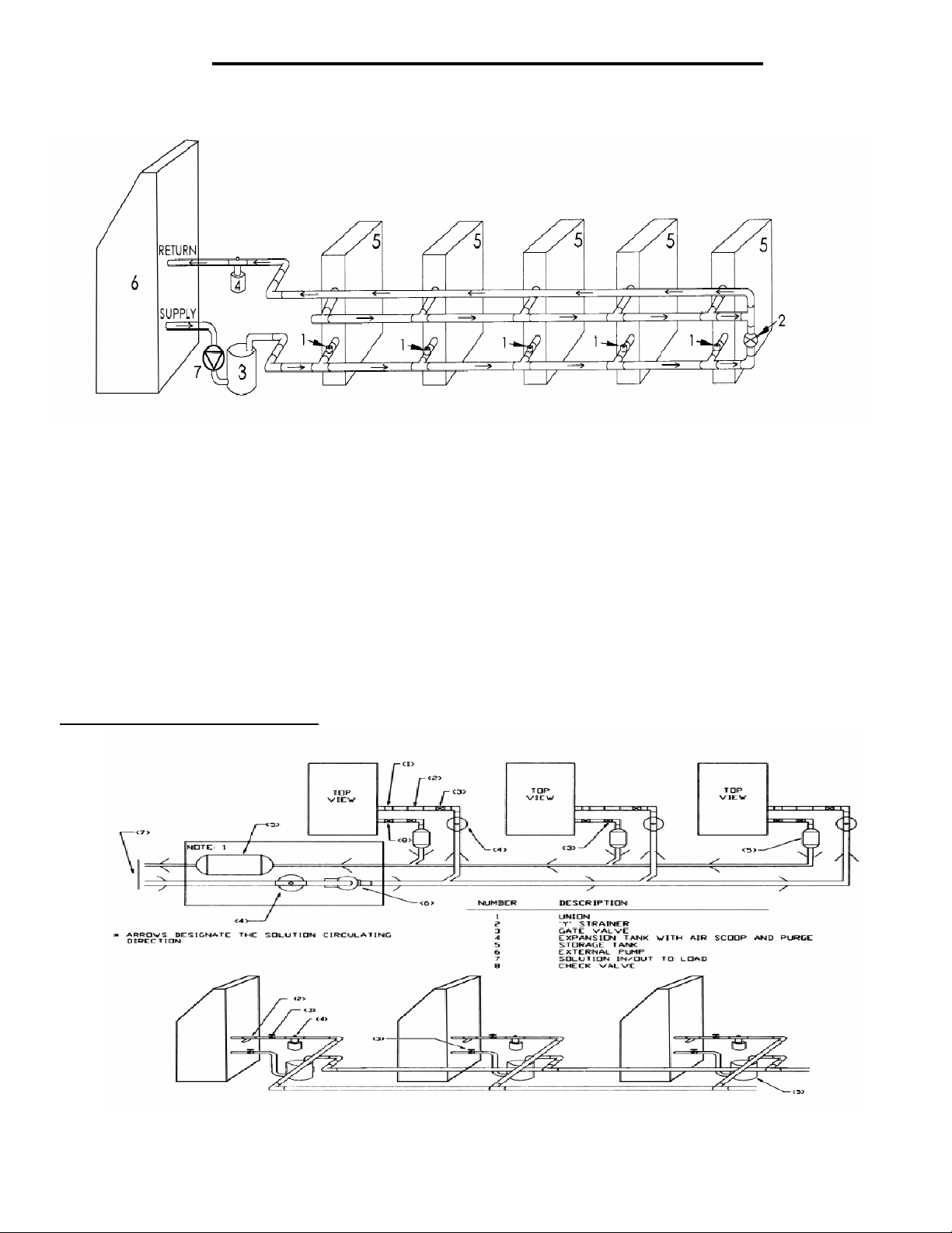
Composite Piping Layout and Design
Understanding the function and friction loss of each part of the piping system is important to the layout and successful
installation of a chilled liquid solution system.
2-Way Liquid Solution Control Valves
1-
Bypass Valve
2-
Storage Tank
3-
Expansion Tank
4-
Coil
5-
Chiller
6-
Pump
7-
The circulation pump is the key performer in the piping system. The pump must circulate the liquid solution through the
heat exchanger and piping system to the air handlers. Pumps are designed to deliver a flow rate measured in gallons
per minute(GPM). The pump must be able to overcome the resistance to flow (pressure drop) imposed by the chiller
components, piping system and air handlers while maintain the necessary flow rates in gallons per minute. Pump
capacities in gallons per minute and pressure drop (feet of head) are listed in table 1.
Banked Chiller Configuration
Notes:
Installing Multiaqua chillers in parallel is recommended.
69
An adjustable valve must be used to throttle the discharge liquid solution flow rate to appropriate levels based
on capacity and glycol mix percentages.
MAC036
Compressor
Refrigerant
Heat Exchanger
Max.Head Pressure
Max Flow rate
Min Flow Rate
Supply Water Temp
Return Water Temp
Min Solution Content
Expansion Tank Size
Pump
Copeland Scroll
R407c
Brazed Plate
50 ft
8.6 gpm
5.5 gpm
44°
55°
25 Gallons
2 Gallons
0.5 HP
Water Connections 1" Supply & 1.25 Return
Internal Pressure Loss
1.77 ft of hd
1" Supply & 1.25" Return
MAC048
Copeland Scroll
R407c
Brazed late
50 ft
11.5 gpm
6.5 gpm
44°
55°
25 Gallons
2 Gallons
0.5 HP
1.68 ft of head
MAC060
Copeland Scroll
R407c
Brazed Plate
50 ft
14.4 gpm
9.0 gpm
44°
55°
25 gallons
2 Gallons
0.5 HP
1"Supply & 1.25" Return
1.68 ft of head
Piping resistance or pressure drop is measured in feet of head. A foot of head is the amount of pressure drop imposed
in lifting liquid solution one foot. Pumps in the Multiaqua system are designed to move rated liquid solution flow
in GPMs.
70

o
m
Installation Notes:
Piping such as PEX, steel, copper or PVC can be used with the Multiaqua system. Check local building codes for
material conformation. Care must be taken when using PVC as the presence of propylene glycol may destroy
plastics. Pressure drop data for the selected piping material is readily available and should be used. Should the
Multiaqua chiller be installed using existing steel (ferrous metal) piping system, dielectric fittings must be used
at the chiller and air handler. The factory supplied wye strainer will capture particles of rust and sediment
inherent with steel piping and should be checked and cleaned after initial start up and open a regular maintenance
during the life of the system.
Any piping used to conduct liquid solution must be insulated in accordance with local and national mechanical
codes. Information on insulation installation and application can be obtained from Armaflex web site at
www.armaflex.com
of the chiller and air handlers, it is suggested that shutoff valves be installed at the chiller and air handler (s). If
ball valves are used, they can double as balancing valve (s) in the supply piping at each air handler. Chiller
shutoff valves should be attached at the chiller connections with unions.
The air handlers are to be controlled with electrically operated "slow-opening" solenoid valves, circulators or
motorized zone valves as manufactured by Erie controls (www.eriecontrols.com/products/index.htm) A remote
thermostat or air handler installed digital control operates the valves.
and Owens-Corning site atwww.owenscorning.com/mechanical/pipe/. For future servicing
Bypass valves as shown in drawing 1, should be installed between the supply and the return chilled liquid
solution supply pipes at a convenient location to the installation. The bypass valve operates to bypass liquid soluti
between the supply and return chilled liquid solution lines. In the event air handlers valves should shut down, the
bypass valve is set to open up and bypass liquid solution between the supply and return lines, relieving pressure
and eliminating the possibility of pump cavitations. To adjust the valve, run the system with one air handler
solenoid actuated. De-energize the solenoid valve, (at this point no liquid solution will be flowing through the air
handlers.) and adjust the bypass valve to relieve pressure between the supply and return piping.
Bleed ports will be factory installed on all Multiaqua air handlers. Bleed ports are opened to eliminate air trapped
in the air handlers after filling the system with liquid solution and Propylene Glycol, and before operating the
refrigerant compressor in the chiller.
The minimum liquid solution content in the chiller system, (piping, chiller, and air handlers), is 25 U.S. gallons.
Estimate the system liquid solution content. Should the system have less than 50 gallons of liquid solution
content, a chilled liquid solution storage tank must be installed. The tank stores enough chilled liquid solution
to prevent frequent chiller compressor cycles at light load and prevents chilled liquid temperature swings at
higher load conditions when the chiller compressor is waiting to cycle on the time delay control.
Propylene Glycol must be added to the water used in the syste
low ambient temperature conditions and low chilled liquid solution temperatures. In comparison to water,
Propylene Glycol slightly lessons the temperature exchange in the chiller heat exchanger. However, that is
offset by the increased flow of liquid solution through the piping system enabled by the Propylene Glycol. To
determine the Propylene Glycol content for various ambient temperatures refer to table 6 page 72.
. Propylene helps prevent freeze-ups due to
In no instance should a Multiaqua chiller be installed with less than 10% Propylene Glycol content in the piping
system. Using less than the recommended Propylene Glycol percentage content voids equipment warranty.
71

.
l
Polypropylene Glycol System Content vs.
Minimum Ambient Temperature
To not engage in cold ambient mitigation will result in the failure of components, property damage and
void warranty.
Table 6
Propylene Water
Glycol % Flow
10% x 1.020
20% x 1.028
30% x 1.036
40% x 1.048
50% x 1.057
Ethylene Glycol is environmentally hazardous and not recommended
automotive coolant) is not to be used in a Multiaqua Chiller under any circumstances. Dow Chemical's "Ambitrol"
family of Glycol-based coolants of food grade Propylene Glycol is suggested. Information on Ambitrol is available
from Dow at www.dow.com, search word "Ambitrol".
Capacity
x .99
x .98
x .98
x .97
Min. Ambient
Temperature
26°F
18°F
8°F
-7°F
-29°F
Expansion Tanks:
GPM Adjustment
= 100 % Capacity
x 1.01
x 1.03
x 1.07
x 1.11
x 1.16x .96
Inhibited Propylene Glycol ( typica
Liquid solution expansion and contraction within the closed system must be compensated for with an expansion
tank. The expansion tank used with the Multiaqua system, is a steel tank with a rubber bladder attached to it
internally. There is air pressure on one side of the rubber bladder that keeps the bladder pushed against the
sides of the tank before the system is filled with liquid solution (illustration above). As the liquid solution heats
up the bladder, will be pushed further away from the tank walls, allowing for expansion and contracting as the
liquid solution temperature changes. By flexing, the bladder controls the system pressure adjusting to
temperature variations of the chilled liquid solution system.
It is critical that the expansion tank's air bladder pressure be less than the system solution pressure. Air
pressure can be measured with an automotive tire gauge at the bicycle valve port on the expansion tank. Bleeding
air out of the bladder or increasing the pressure with a bicycle pump will adjust pressure.
System must use a liquid solution storage tank if system volume is less than 50 U.S. gallons.
72

0
d
Filling System with Liquid Solution and Coolant
A
(Propylene Glycol)
Concentrations of Propylene Glycol in excess of 50% will destroy o-rings in fittings and pump. Water should
be added to the system first or a liquid solution diluted Propylene Glycol mix.
Before filling system with Propylene Glycol and water, pressure test the piping system with compressed air.
Testing should be done at a minimum of 50 psi but no greater than 50 psi over the system's normal operating
pressure. The system should hold air pressure for a minimum of one hour with no leakage.
System that contains 50 or more U.S. gallons should have a tee fitting with a stopcock installed in the return
line close to the chiller. The stopcock can be opened and attached to a hose with a female X female hose
fitting. In the open end of the hose section (1 -1.5 feet long) insert a funnel and pour into the system the
diluted Propylene Glycol/liquid solution mixture or add water first and then the quantity of Propylene Glycol
needed for minimum ambient protection (refer to Table 6). After adding the Propylene Glycol /water mixture, or
liquid solution and then coolant proceed to add enough water to the system to achieve a 15 psi gauge pressure.
To measure system pressure shut off the stopcock, remove hose and attach a water pressure gauge. Open
the stopcock to read system pressure.
Systems that use the Chilled Liquid Solution Storage Tank should be filled at the tee/stopcock fitting in the
outlet fitting of the storage tank. Fill the tanks with 10 gallons of water and with a funnel pour the calculated
(refer to Table 6) amount of Propylene Glycol into the tank. The amount of Propylene Glycol added should be
calculated to achieve minimum ambient protection. After adding Propylene Glycol, fill the system with enough
liquid solution to bring system pressure to approximately 15 psi gauge pressure. To measure system pressure
shut off the stopcock and attach a water pressure gauge. Open the stopcock to read system pressure.
ir Elimination
Since we have the system filled we must eliminate the air left in the system. Briefly open each bleed valve at
the air handlers and allow trapped air to escape. This will eliminate much of the air left in the system.
Next we will start the pump and continue bleeding air from the system. Be sure the chiller has line voltage
available to it and set the chilled liquid solution control up to 10
at this point. The pump should now start and remain running. Should the pump stop at any time during this
process it is an indication that the flow switch had air move across it allowing the circuit to be interrupted.
Continue to bleed some air out of the system at the highest locations before resetting the pump bypass timer
to get the pump running again. Open and close the power supply switch to the chiller to restart the pump.
Continue bleeding air with the pump operating. You may have to start and re-start the pump a few times to
complete air removal.
All piping systems should have a minimum of 10% Propylene Glycol in the system even in climates with non-
freezing ambient temperatures.
Using less than the recommended Propylene Glycol percentage content voids equipment warranty.
Liquid solution control valves (solenoid or motorized valves) should be selected for low pressure drop. If a selecte
valve contributes to pushing your total head calculation to more than 50 feet of head, a larger valve may be
needed to bring your total head below the maximum of 50 feet.
°F, which will ensure that only the pump runs
Liquid Solution Balancing:
Liquid solution balancing will require an accurate digital thermometer to measure return line liquid solution
temperature at each air handler. Set the chilled liquid solution temperature control in the chiller at a normal
operational temperature (44°F) and measure pump discharge temperature with the digital thermometer to check
system solution temperature. After the chilled liquid solution temperature has lowered to the set point begin the
balancing process. The system must be free of air and each air handler set at a temperature low enough to
continue cooling operation (and liquid solution flow) during the balancing process. Begin by measuring the return
line chilled liquid solution temperature of each air handler. Begin incrementally closing the supply line balance
valve at the air handlers with the lowest return line chilled liquid solution temperature. Continue this process
until each air handler has close to the same return line chilled liquid solution temperature.
73

MAC060-3 Ladder Wiring Diagram
380/460-3-50/60
74

MAC060-3 Wiring Diagram
380/460-3-50/60
75

MAC060-3-L with Low Ambient Kit Wiring Diagram
380/460-3-50/60
76

MAC036, 048 & 060-2 Ladder Wiring Diagram
208/230-3-50/60
77

MAC036, 048 & 060-2 Wiring Diagram
208/230-3-50/60
78

MAC036, 048 & 060-2-L with Low Ambient Kit Wiring Diagram
208/230-3-50/60
79

MAC036, 048 & 060-1 Ladder Wiring Diagram
208/230-1-50/60
80

MAC036, 048 & 060-1 Wiring Diagram
208/230-1-50/60
81

MAC036, 048 & 060-1-L with Low Ambient Kit Wiring Diagram
208/230-1-50/60
82

MAC036, 048 & 060 CERTIFIED DRAWING
83

MHCCW Chilled Water Ceiling Conceale
d
With or Without Electric Heat
2-Pipe Heat / Cool Fan Coil 12,000 - 36,000 BTUH
84

MHCCW NOMENCLATURE BREAKDOWN
2-Pipe Heat/Cool Ceiling Concealed Fan Coil with Electric Heat
MHCCW XX - XX - XX
Voltage "See Notes"
00= 208/230-1-50/60
120-1-60
03=
2-Pipe Heat/Cool
w/ Electric Heat
Nominal CFM
04 = 1 TON
06 = 1.5 TON
08 = 2 TON
10 = 2.5 TON
12 = 3 TON
Electric Heat
00= 0 KW
02 =2KW "See Note 2 & 3"
03= 3 KW
05= 5 KW
06= 6 KW
08= 8 KW
Notes:
1. The standard unit is 208/230-1-50/60 vac. Add suffix 03 for 120-1-50/60 vac units.
2. 120 vac units are available without electric heat or 2kw of electric heat.
3. 2 KW electric heat is only available with 120 vac.
Available Model Numbers
MHCCW06-00-03
MHCCW04-02-03
MHCCW04-00
MHCCW04-03 MHCCW10-03 MHCCW12-03
MHCCW04-05
MHCCW04-06
MHCCW04-08
MHCCW06-02-03 MHCCW08-02-03 MHCCW10-02-03 MHCCW12-02-03
MHCCW06-00
MHCCW06-03
MHCCW06-05 MHCCW10-05MHCCW08-05
MHCCW06-06
MHCCW06-08
MHCCW08-00-03MHCCW04-00-03
MHCCW08-00
MHCCW08-03
MHCCW08-06
MHCCW08-08
MHCCW10-00-03
MHCCW10-00
MHCCW10-06
MHCCW10-08
MHCCW12-00-03
MHCCW12-00
MHCCW12-05
MHCCW12-06
MHCCW12-08
85

HVAC Guide Specifications
Chilled Water Fan Coil with Electric Heat
2-Pipe
Nominal Size:
12,000 – 36,000 BTUH
Multiaqua Model Number:
MHCCW04
MHCCW06
MHCCW08
MHCCW10
MHCCW12
Part 1-General
1.01 System Description
Multiaqua Chilled Water Fan Coils are manufactured with heavy gauge galvanized steel to resist corrosion.
1.02 Quality Assurance
A. Certified in accordance with U.L. Standard 95, latest version (U.S.A.)
B. Manufactured in a facility registered to ISO 9002, Manufacturing Quality Standard.
C. Fully load tested at the factory.
D. Damage resistant packaging.
1.03 Delivery, Storage and Handling
A. Packaged and readied for shipment from the factory.
B. Controls shall be capable of withstanding 150°F storage temperatures in the control compartment.
C. Stored and handled per manufacturer’s rec o mmendations.
Part 2-Product
2.01 Equipment
A. General:
1. Unit shall be a factory assembled and tested chilled or hot water fan coil with electric heat.
2. Shall be assembled with heavy gauge galvanized steel.
3. Contained with the unit shall be all factory wiring, piping, associated controls and special
accessories required prior to start up.
B. Unit Cabinet:
1. Composed of heavy gauge galvanized steel casing with a baked polyester powder.
2. Shall be internally insulated to insure quiet operation.
C. Fan Motors:
1. Fan motors shall be three speed, direct drive, and PSC type.
2. Totally enclosed.
3. Internal overload protected.
D. Blower Wheels:
1. Blower wheels are forward curved and dynamically balanced.
E. Water Coil:
1. Manufactured with 3/8” copper tubing mechanically bonded to aluminum fins.
2. Contain both a manual water drain and air bleed port.
3.
Coils shall be factory tested to 350 psig.
4. Coils shall be capable of being field converted from right to left hand connection.
F. Drain Pan:
1. All drain pans shall be coated on both the interior and exterior with baked polyester powder to
resist corrosion.
2. The exterior of all drain pans shall be insulated with closed cell to prevent condensation.
3. Pans shall contain a left and right hand primary sloped drain connection as well as a right hand
sloped secondary drain connection.
86

G. Electric Heat:
1. Electric Heaters shall be of the rod and disk type.
2. Shall be protected by safeties.
Part 3-Controls and Safeties
3.01 Controls
A. Fan coils shall be completely factory wired and tested.
B. All components shall be wired to an internal terminal block to allow for a field installed thermostat and or
Fan speed control.
C. Controls shall include the following components.
1. 24vac transformer.
2. Fan relays.
3. Electric heat sequencer (s).
4. Optional Thermostats.
3.02 Safeties
A. Fan coil shall be equipped with all necessary components in conjunction with the
control system to provide the following protectants.
1. High temperature.
2. Over current protection.
Part 4-Operating Characteristics:
4.01 Electrical Requirements
A. Primary electrical power supply shall enter the unit at a single location.
B. Electrical power supply shall be rated to withstand 120°F operating ambient temperatures.
D. Control and high voltage points shall be accessed through terminal block.
Part 5- Accessories:
5.01 Enclosures
A. Fan coils shall be capable of incorporating enclosures.
1. Enclosures shall be internally insulated to insure quite operation and increase efficiency.
2. Shall include knockouts for ease of piping and electrical in and out of the enclosures.
3. Shall include an optional return air cutout in the enclosure.
4. Shall include a supply air duct flange.
5. Shall incorporate baked polyester powder service access panels with and without a filtered louver.
87

MHCCW Product Specifications
Physical Data
Model
Number
Height
(in)
Width
(in)
Depth
(in)
Weight
(lbs)
Coil
Rows
FPI
Copper
Diameter
(in)
Water
Inlet (in)
MHCCW04 10.25 37.72 21.65 66.0 2-14 3/8 5/8 5/8 3/4
MHCCW06 10.25 37.72 21.65 68.2 3-14 3/8 5/8 5/8 3/4
MHCCW08 10.25 37.72 21.65 72.6 4-14 3/8 5/8 5/8 3/4
MHCCW10 10.25 43.70 21.65 74.8 4-14 3/8 7/8 7/8 3/4
MHCCW12 10.25 49.68 21.65 83.6 4-14 3/8 7/8 7/8 3/4
Electrical Data
Model Number
Nominal
CFM
Volts
Phase
Hertz
Electric
Heat
(KW)
Motor HP
Full Load
Ampacity
Fuse or HACR Circuit
MHCCW04-00 0 0.82 1.03 3
MHCCW04-03 3 13.86 19.31 20
MHCCW04-05 5 22.56 31.6 35
400
1/8
MHCCW04-06 6 26.9 37.6 40
MHCCW04-08
8
35.6 48.3 50
MHCCW06-00 0 1.18 1.48 3
MHCCW06-03 3 14.22 19.76 20
MHCCW06-05 5 22.92 32.05 35
600
1/8
MHCCW06-06 6 27.27 38.05 40
MHCCW06-08
8
35.96 48.75 50
MHCCW08-00 0 1.43 1.8 4
MHCCW08-03 3 14.47 20.08 20
MHCCW08-05 5 23.17 32.36 35
800
1/4
MHCCW08-06 6 27.52 38.36 40
MHCCW08-08
MHCCW10-00 0 1.43 1.8 4
208/230-1-50/60
8
36.21 49.06 50
MHCCW10-03 3 14.47 20.08 20
MHCCW10-05 5 23.17 32.36 35
1000
1/4
MHCCW10-06 6 27.52 38.36 40
MHCCW10-08
8
36.21 49.06 50
MHCCW12-00 0 1.81 2.26 5
MHCCW12-03 3 14.85 20.55 20
MHCCW12-05 5 23.55 32.84 35
1200
1/4
MHCCW12-06 6 27.9 38.84 40
MHCCW12-08
Model Number
Nominal
CFM
Volts
Phase
Hertz
8
Electric
Heat
(KW)
Motor
HP
36.6 49.54 50
Full Load
Ampacity
Fuse or HACR Circuit
Breaker Per Circuit
Minimum
Amps
MHCCW04-00-03 400 0 1/30 0.55 .69 1.25
MHCCW06-00-03 600 0 1/30 0.55 .69 1.25
MHCCW08-00-03 800 0 1/30 0.55 .69 1.25
MHCCW10-00-03 1000 0 1/8 1.80 2.25 5
MHCCW12-00-03 1200
These specifications are subject to change without notice.
120-1-60
0 1/4 3.00 3.75 10
88
Water
Outlet
(in)
Breaker Per Circuit
Minimum
Amps
Maximum
Maximum
Amps
Drain
(in)
Amps

MHCCW Chilled Water Performance Data
MHCCW04 COOLING CAPACITIES
NOMINAL
CFM
400 42
EWT
(°F)
GPM
1.5 4.4
2.0 7.2
2.5 10.7
3.0 14.7
PRESSURE
DROP (ft)
ENTERING AIR TEMPERATURE (°F)
80° D.B. / 67° W.B. 75° D.B. / 63° W.B.
TC 11.8 9.0
SC 8.9 7.8
WTR 15.7 12.0
TC 13.4 10.2
SC 9.5 8.3
WTR 13.4 10.2
TC 14.3 11.0
SC 9.8 8.6
WTR 11.5 8.8
TC 15.1 11.5
SC 10.1 8.8
WTR 10.1 7.7
MHCCW04 COOLING CAPACITIES
NOMINAL
CFM
400 45
EWT
(°F)
GPM
PRESSURE
DROP (ft)
1.5 4.4
2.0 7.2
2.5 10.7
3.0 14.7
These specifications are subject to change without notice.
ENTERING AIR TEMPERATURE (°F)
80° D.B. / 67° W.B. 75° D.B. / 63° W.B.
TC 10.5 8.3
SC 8.5 7.5
WTR 14.4 11.0
TC 12.3 9.4
SC 9.1 8.0
WTR 12.3 9.4
TC 13.2 10.0
SC 9.4 8.2
WTR 10.5 8.0
TC 13.8 10.6
SC 9.6 8.4
WTR 9.2 7.0
89

MHCCW Chilled Water Performance Data
MHCCW06 COOLING CAPACITIES
NOMINAL
CFM
600 42
NOMINAL
CFM
600 45
EWT
(°F)
EWT
(°F)
GPM
3.0 3.8
4.0 6.5
5.0 9.8
6.0 13.8
PRESSURE
DROP (ft)
ENTERING AIR TEMPERATURE (°F)
80° D.B. / 67° W.B. 75° D.B. / 63° W.B.
TC 18.5 14.1
SC 13.4 11.7
WTR 12.3 9.4
TC 20.4 15.6
SC 14.1 12.3
WTR 10.2 7.8
TC 21.6 16.5
SC 14.5 12.6
WTR 8.6 6.6
TC 22.4 17.1
SC 14.8 12.9
WTR 7.5 5.7
MHCCW06 COOLING CAPACITIES
GPM
3.0 3.8
4.0 6.5
5.0 9.8
6.0 13.8
PRESSURE
DROP (ft)
ENTERING AIR TEMPERATURE (°F)
80° D.B. / 67° W.B. 75° D.B. / 63° W.B.
TC 17 13.0
SC 12.8 11.2
WTR 11.3 8.6
TC 18.7 14.3
SC 13.4 11.8
WTR 9.4 7.2
TC 19.8 15.1
SC 13.8 12.1
WTR 7.9 6.0
TC 20.6 15.7
SC 14.1 12.3
WTR 6.9 5.2
These specifications are subject to change without notice.
90

MHCCW Chilled Water Performance Data
MHCCW08 COOLING CAPACITIES
NOMINAL
CFM
800 42
NOMINAL
CFM
800 45
EWT
(°F)
EWT
(°F)
GPM
3.0 3.9
4.0 6.5
5.0 9.6
6.0 13.3
PRESSURE
DROP (ft)
ENTERING AIR TEMPERATURE (°F)
80° D.B. / 67° W.B. 75° D.B. / 63° W.B.
TC 22.7 17.3
SC 17.5 15.4
WTR 15.1 11.5
TC 25.9 19.7
SC 18.6 16.3
WTR 12.9 9.9
TC 28 21.4
SC 19.5 17.0
WTR 11.2 8.6
TC 29.4 22.5
SC 20.0 17.4
WTR 9.8 7.5
MHCCW08 COOLING CAPACITIES
GPM
3.0 3.9
4.0 6.5
5.0 9.6
6.0 13.3
PRESSURE
DROP (ft)
ENTERING AIR TEMPERATURE (°F)
80° D.B. / 67° W.B. 75° D.B. / 63° W.B.
TC 20.8 15.9
SC 16.6 14.7
WTR 13.9 10.6
TC 23.4 17.9
SC 17.6 15.5
WTR 11.7 8.9
TC 25.1 19.2
SC 18.2 16.0
WTR 10.0 7.7
TC 26.4 20.1
SC 18.7 16.3
WTR 8.8 6.7
These specifications are subject to change without notice.
91

MHCCW Chilled Water Performance Data
MHCCW10 COOLING CAPACITIES
NOMINAL
CFM
1000 42
NOMINAL
CFM
1000 45
EWT
(°F)
EWT
(°F)
GPM
4.0 4.9
5.0 7.4
7.0 14.1
PRESSURE
DROP (ft)
6 10.5
ENTERING AIR TEMPERATURE (°F)
80° D.B. / 67° W.B. 75° D.B. / 63° W.B.
TC 28.8 22.0
SC 21.9 19.3
WTR 14.4 11.0
TC 31.8 24.3
SC 23 20.1
WTR 12.7 9.7
TC 33.9 25.9
SC 23.8 20.8
WTR 11.3 8.6
TC 35.5 27.1
SC 24.4 21.3
WTR 10.2 7.8
MHCCW10 COOLING CAPACITIES
GPM
4.0 4.9
5.0 7.4
7.0 14.1
PRESSURE
DROP (ft)
6 10.5
ENTERING AIR TEMPERATURE (°F)
80° D.B. / 67° W.B. 75° D.B. / 63° W.B.
TC 26.4 20.2
SC 21.0 18.6
WTR 13.2 10.1
TC 29.2 22.3
SC 22.0 19.4
WTR 11.7 8.9
TC 31.1 23.8
SC 22.8 19.9
WTR 10.4 7.9
TC 32.6 24.9
SC 23.3 20.4
WTR 9.3 7.1
These specifications are subject to change without notice.
92

MHCCW Chilled Water Performance Data
MHCCW12 COOLING CAPACITIES
NOMINAL
CFM
1200 42
NOMINAL
CFM
1200 45
EWT
(°F)
EWT
(°F)
GPM
4.0 5.6
5.0 8.5
7.0 16.1
PRESSURE
DROP (ft)
6 12.0
ENTERING AIR TEMPERATURE (°F)
80° D.B. / 67° W.B. 75° D.B. / 63° W.B.
TC 32.3 24.7
SC 25.4 22.4
WTR 16.2 12.4
TC 36.1 27.6
SC 26.8 23.5
WTR 14.4 11.0
TC 38.9 29.7
SC 27.8 24.3
WTR 13 9.9
TC 40.9 31.2
SC 28.6 24.9
WTR 11.7 8.9
MHCCW12 COOLING CAPACITIES
GPM
4.0 5.6
5.0 8.5
7.0 16.1
PRESSURE
DROP (ft)
6 12.0
ENTERING AIR TEMPERATURE (°F)
80° D.B. / 67° W.B. 75° D.B. / 63° W.B.
TC 29.7 24.6
SC 24.4 20.6
WTR 14.8 12.3
TC 33.1 25.3
SC 25.7 22.6
WTR 13.3 10.1
TC 35.7 27.2
SC 26.6 23.4
WTR 11.9 9.1
TC 37.5 28.7
SC 27.3 23.9
WTR 10.7 8.2
These specifications are subject to change without notice.
93

MHCCW Hot Water Performance Data
ENTERING NOMINAL
AIR (°F) CFM
50 400
ENTERING NOMINAL
AIR (°F) CFM
60 400
MHCCW-04-00 HOT WATER CAPACITIES
GPM WPD
1.5 3.6 13.0 15.6 18.1 20.7 23.3 25.9 28.5 31.1 33.7 36.3 38.9
2.0 6.0 13.6 16.3 19.0 21.7 24.4 27.1 29.8 32.5 35.2 37.9 40.7
2.5 9.0 13.9 16.7 19.5 22.3 25.0 27.8 30.6 33.4 36.2 39.0 41.7
3.0 12.6 14.2 17.0 19.9 22.7 25.5 28.4 31.2 34.0 36.9 39.7 42.5
100° 110° 120° 130° 140° 150° 160° 170° 180° 190° 200°
MHCCW-04-00 HOT WATER CAPACITIES
GPM WPD
1.5 3.6 10.4 13.0 15.6 18.1 20.7 23.3 25.9 28.5 31.1 33.7 36.3
2.0 6.0 10.8 13.6 16.3 19.0 21.7 24.4 27.1 29.8 32.5 35.2 37.9
2.5 9.0 11.1 13.9 16.7 19.5 22.3 25.0 27.8 30.6 33.4 36.2 39.0
3.0 12.6 11.3 14.2 17.0 19.9 22.7 25.5 28.4 31.2 34.0 36.9 39.7
100° 110° 120° 130° 140° 150° 160° 170° 180° 190° 200°
ENTERING WATER TEMPERATURE (°F)
ENTERING WATER TEMPERATURE (°F)
ENTERING NOMINAL
AIR (°F) CFM
70 400
ENTERING NOMINAL
AIR (°F) CFM
80 400
MHCCW-04-00 HOT WATER CAPACITIES
GPM WPD
1.5 3.6 7.8 10.4 13.0 15.6 18.1 20.7 23.3 25.9 28.5 31.1 33.7
2.0 6.0 8.1 10.8 13.6 16.3 19.0 21.7 24.4 27.1 29.8 32.5 35.2
2.5 9.0 8.3 11.1 13.9 16.7 19.5 22.3 25.0 27.8 30.6 33.4 36.2
3.0 12.6 8.5 11.3 14.2 17.0 19.9 22.7 25.5 28.4 31.2 34.0 36.9
100° 110° 120° 130° 140° 150° 160° 170° 180° 190° 200°
ENTERING WATER TEMPERATURE (°F)
MHCCW-04-00 HOT WATER CAPACITIES
GPM WPD
1.5 3.6 5.2 7.8 10.4 13.0 15.6 18.1 20.7 23.3 25.9 28.5 31.1
2.0 6.0 5.4 8.1 10.8 13.6 16.3 19.0 21.7 24.4 27.1 29.8 32.5
2.5 9.0 5.6 8.3 11.1 13.9 16.7 19.5 22.3 25.0 27.8 30.6 33.4
3.0 12.6 5.7 8.5 11.3 14.2 17.0 19.9 22.7 25.5 28.4 31.2 34.0
100° 110° 120° 130° 140° 150° 160° 170° 180° 190° 200°
ENTERING WATER TEMPERATURE (°F)
These specifications are subject to change without notice.
94

MHCCW Hot Water Performance Data
ENTERING NOMINAL
AIR (°F) CFM
50 600
ENTERING NOMINAL
AIR (°F) CFM
60 600
MHCCW-06-00 HOT WATER CAPACITIES
GPM WPD
3.0 3.8 22.6 27.1 31.7 36.2 40.7 45.2 49.8 54.3 58.8 63.3 67.9
4.0 6.5 23.6 28.3 33.1 37.8 42.5 47.2 52.0 56.7 61.4 66.1 70.9
5.0 9.8 24.2 29.1 33.9 39.8 43.6 48.5 53.3 58.1 63.0 67.8 72.7
6.0 13.8 24.7 29.6 34.5 39.5 44.4 49.3 54.3 59.2 64.1 69.0 74.0
100° 110° 120° 130° 140° 150° 160° 170° 180° 190° 200°
MHCCW-06-00 HOT WATER CAPACITIES
GPM WPD
3.0 3.8 18.1 22.6 27.1 31.7 36.2 40.7 45.2 49.8 54.3 58.8 63.3
4.0 6.5 18.9 23.6 28.3 33.1 37.8 42.5 47.2 52.0 56.7 61.4 66.1
5.0 9.8 19.4 24.2 29.1 33.9 38.8 43.6 48.5 53.3 58.1 63.0 67.8
6.0 13.8 19.7 24.7 29.6 34.5 39.5 44.4 49.3 54.3 59.2 64.1 69.0
100° 110° 120° 130° 140° 150° 160° 170° 180° 190° 200°
ENTERING WATER TEMPERATURE (°F)
ENTERING WATER TEMPERATURE (°F)
ENTERING NOMINAL
AIR (°F) CFM
70 600
ENTERING NOMINAL
AIR (°F) CFM
80 600
MHCCW-06-00 HOT WATER CAPACITIES
GPM WPD
3.0 3.8 13.6 18.1 22.6 27.1 31.7 36.2 40.7 45.2 49.8 54.3 58.8
4.0 6.5 14.2 18.9 23.6 28.3 33.1 37.8 42.5 47.2 52.0 56.7 61.4
5.0 9.8 14.5 19.4 24.2 29.1 33.9 38.8 43.6 48.5 53.3 58.1 63.0
6.0 13.8 14.8 19.7 24.7 29.6 34.5 39.5 44.4 49.3 54.3 59.2 64.1
100° 110° 120° 130° 140° 150° 160° 170° 180° 190° 200°
ENTERING WATER TEMPERATURE (°F)
MHCCW-06-00 HOT WATER CAPACITIES
GPM WPD
3.0 3.8 9.0 13.6 18.1 22.6 27.1 31.7 36.2 40.7 45.2 49.8 54.3
4.0 6.5 9.4 14.2 18.9 23.6 28.3 33.1 37.8 42.5 47.2 52.0 56.7
5.0 9.8 9.7 14.5 19.4 24.2 29.1 33.9 38.8 43.6 48.5 53.3 59.2
6.0 13.8 9.9 14.8 19.7 24.7 29.6 34.5 39.5 44.4 49.3 54.3 59.2
100° 110° 120° 130° 140° 150° 160° 170° 180° 190° 200°
ENTERING WATER TEMPERATURE (°F)
These specifications are subject to change without notice.
95
 Loading...