

Page 1
Rev. 1.2
Page 2
INSTALLATION & OPERATING
MANUAL
CWA2 Chilled Water Air Handler with Electric Heat
18,000 – 60,000 BTUH
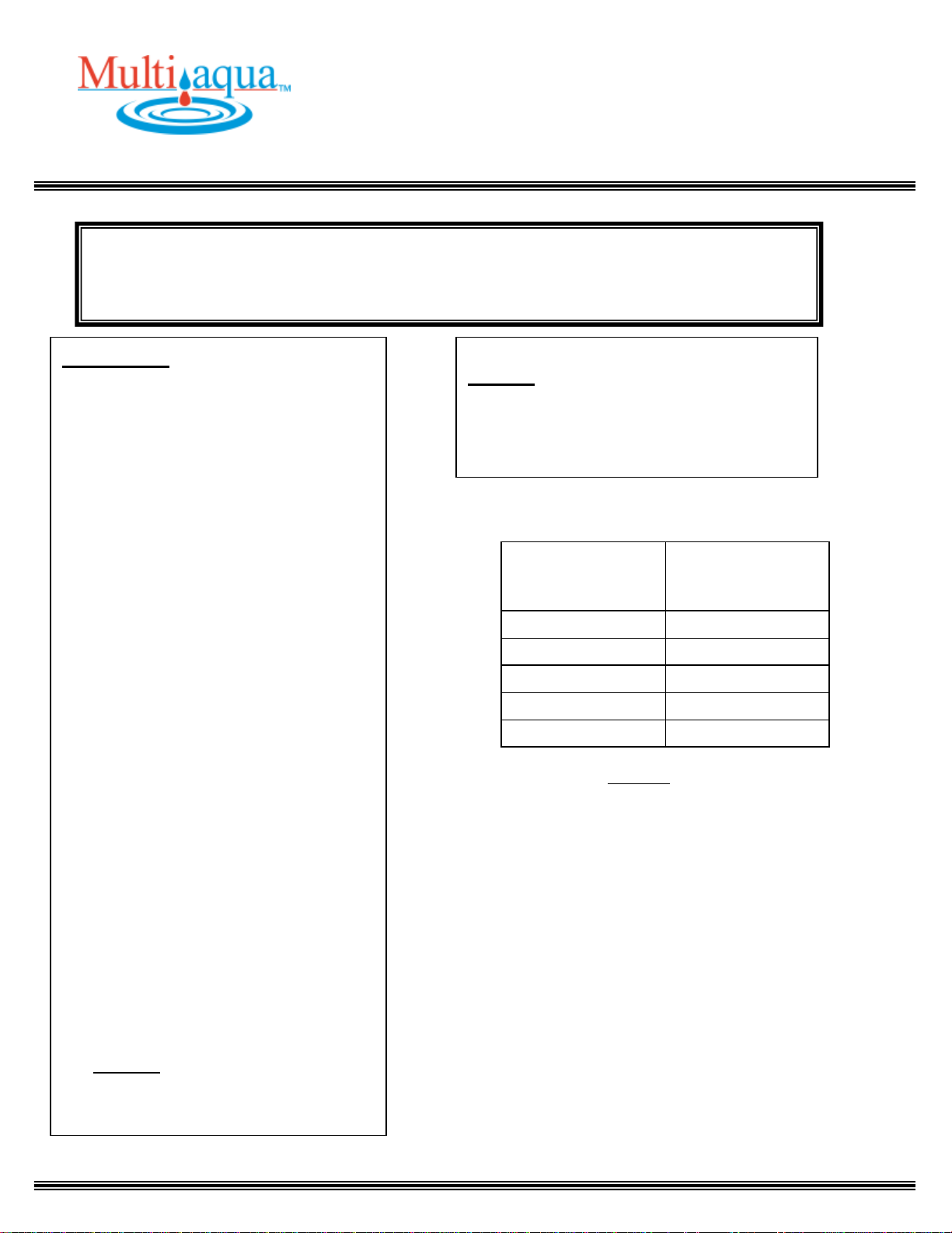
FAN COIL
APPROXIMATED
WEIGHTS (lbs.)
MODEL
NUMBER
18CWA2-00
118
24CWA2-00
118
36CWA2-00
145
48CWA2-00
170
60CWA2-00
180
GENERAL
Read the entire contents of this manual
before beginning installation. Multiaqua
assumes no responsibility for equipment
installed contradictory to any code
requirement or installation instructions.
The components of this fan coil have
been inspected at the factory and readied
for shipment. Upon receiving the
shipment a visual inspection of the
packaging must be performed.
If any damage to the packaging is
discovered, an inspection of the
components must be performed and
noted on the delivery documents. If
component damage is found a damage
claim must be filed by the receiving party
against the delivery party immediately.
This product is designed and
manufactured to permit installation in
accordance with national codes. It is the
installer’s responsibility to install the
product in accordance with national
codes and/or prevailing local codes and
regulations.
Care must be taken to ensure the
structural integrity of the supporting
members, clearances and provisions for
servicing, power supply, coil connections
and/or condensate removal. Before the
installation ensure the structural strength
of the supporting members is sufficient.
See Figure 1 for hanging weights of the
fan coils.
This unit is designed to be installed in a
-------------------------------------- CAUTION --------------------------------------
Care must be taken when handling sheet metal. Sheet metal parts have sharp edges and could
cause injury.
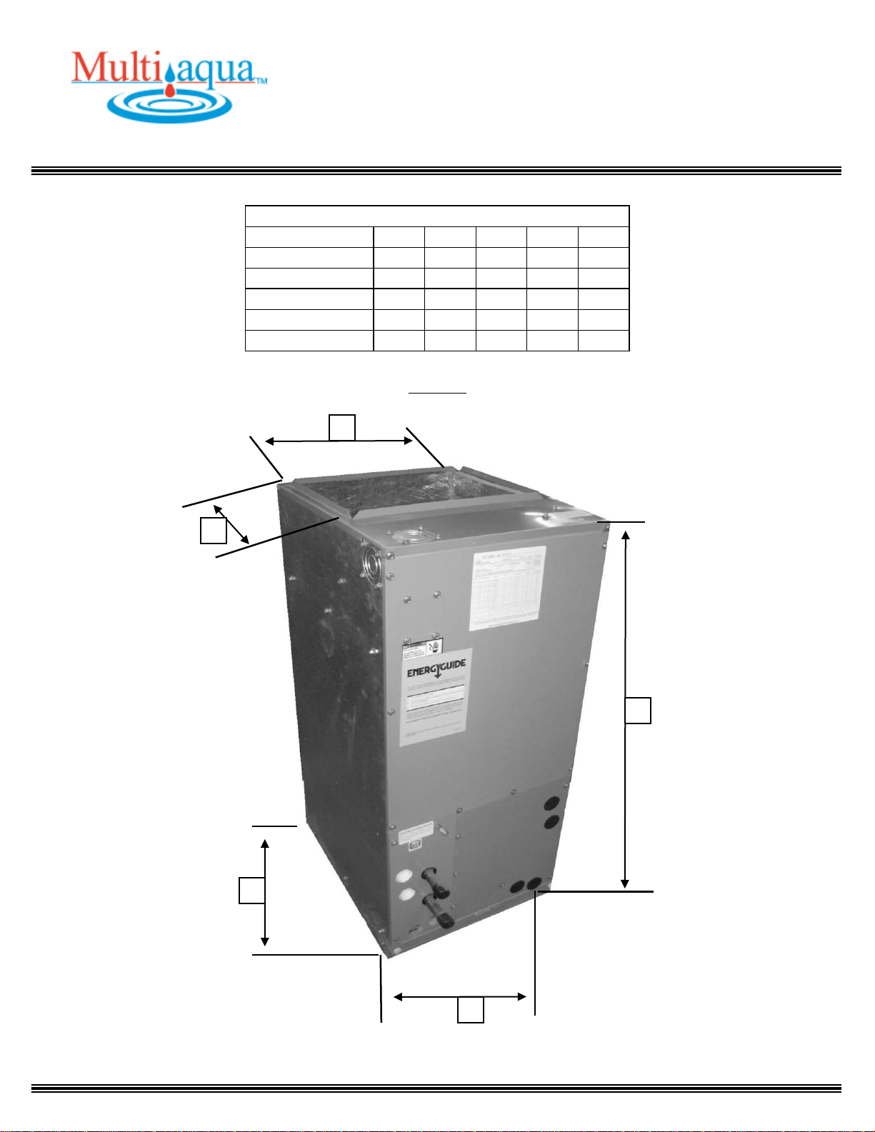
vertical or horizontal configuration. See
Figure 2 for fan coil only dimensions.
The coil hand of connection is field
reversible.
Figure 1
2
Page 3
INSTALLATION & OPERATING
MANUAL
CWA2 Chilled Water Air Handler with Electric Heat
18,000 – 60,000 BTUH
Physical Dimensions (inches)
Model Number
A B C D E
18CWA2-00
17.50
21.00
39.75
12.50
16.00
24CWA2-00
17.50
21.00
39.75
12.50
16.00
36CWA2-00
17.50
21.00
39.75
12.50
16.00
48CWA2-00
21.50
25.00
49.75
17.25
19.50
60CWA2-00
21.50
25.00
49.75
17.25
19.50
A B C E D
Figure 2
3
Page 4
INSTALLATION & OPERATING
MANUAL
CWA2 Chilled Water Air Handler with Electric Heat
18,000 – 60,000 BTUH
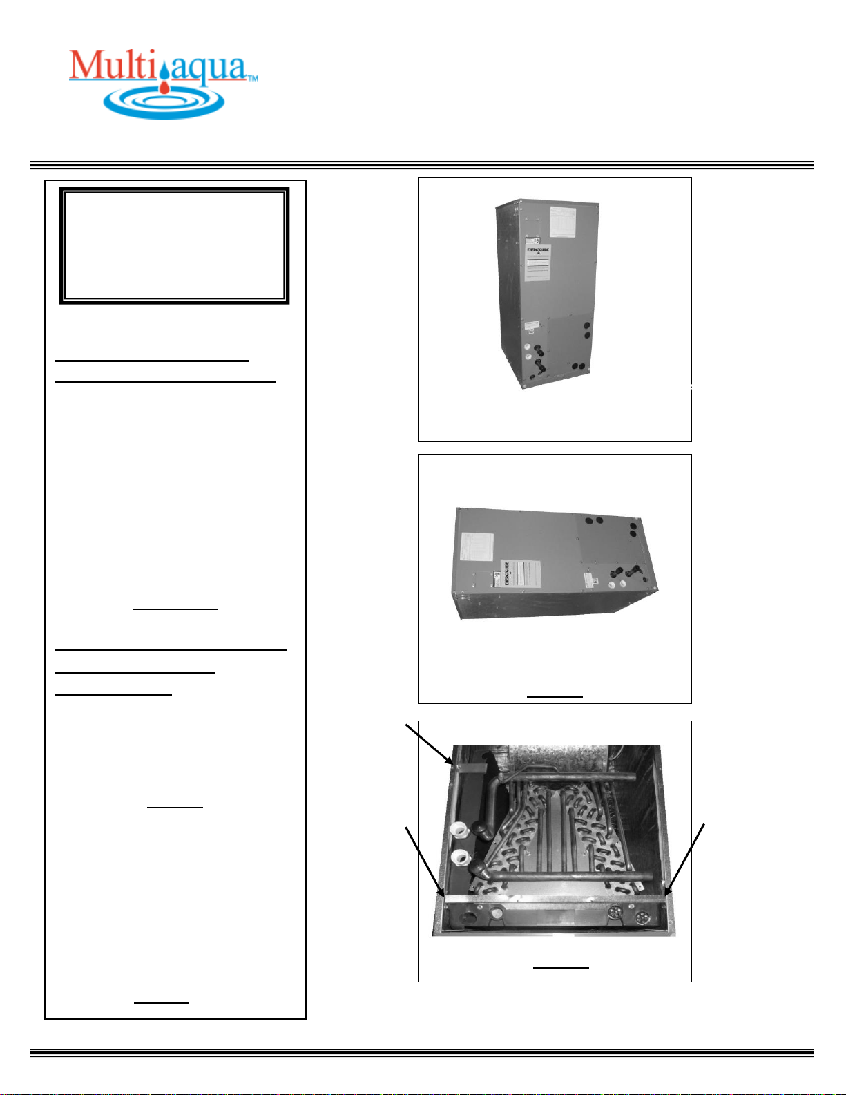
Figure 3
Figure 4
-------- CAUTION -------
Care must be taken when
handling sheet metal. Sheet
metal parts have sharp edges
and could cause injury.
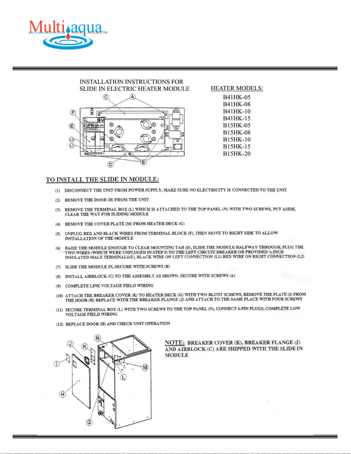
INSTRUCTIONS FOR
INSTALLING FAN COIL
The CWA2 is a chilled water fan
coil with optional electric heat is
designed for multi-position
applications in closets, attics or
basements or crawl spaces. They
are field convertible to horizontal
applications without the need for
additional parts. Unit is not suitable
for down flow applications.
Figure 3 & 4
CONVERTING FAN COIL
TO RIGHT HAND
DISCHARGE
The CWA2 fan coil comes shipped
from the factory assembled with a
left hand air discharge
configuration.
Figure 4
1. To convert the fan coil to right
hand discharge remove the three
front panels.
2. Remove the three screws from
the coil mounting brackets and pull
entire A-coil assembly out of the
fan coil.
Figure 5
Figure 5
4
Page 5
INSTALLATION & OPERATING
MANUAL
CWA2 Chilled Water Air Handler with Electric Heat
18,000 – 60,000 BTUH
Figure 6
UP FLOW DISCHARGE
Figure 8
Figure 7
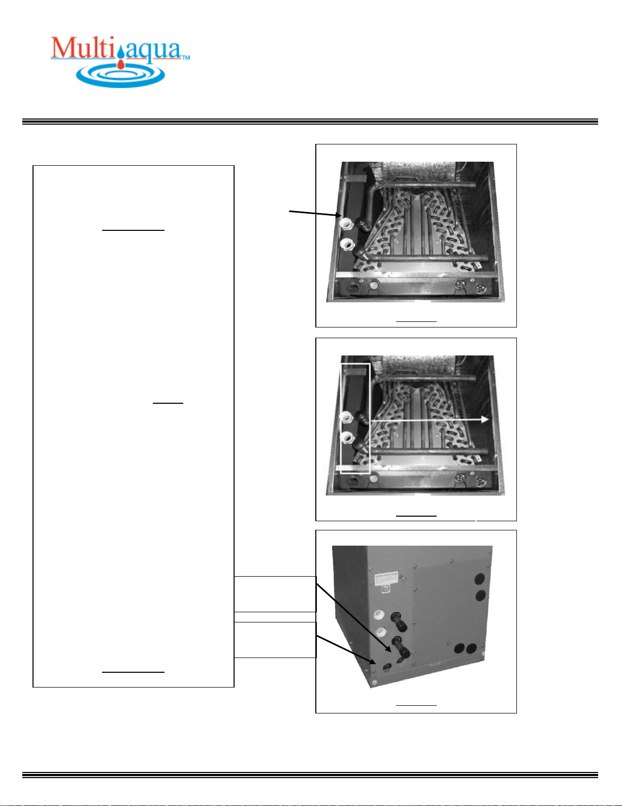
3. Remove the horizontal drain pan
from the coil and re-install it on the
other side.
Figure 6 & 7
4. Ensure the coil mounting brackets
are secure in order to avoid coil
misplacement inside the cabinet.
Check coil slope to make sure that
the drain pan slopes toward the drain
outlet. An incorrectly installed coil
could result in damages to the fan
coil and property.
5. Re-install the three front panels
previously removed in step 1.
6. The unit shall be suitable for 0”
clearance to combustible materials.
Sufficient clearance must be provided
at the front of the fan coil to allow
access for maintenance and servicing.
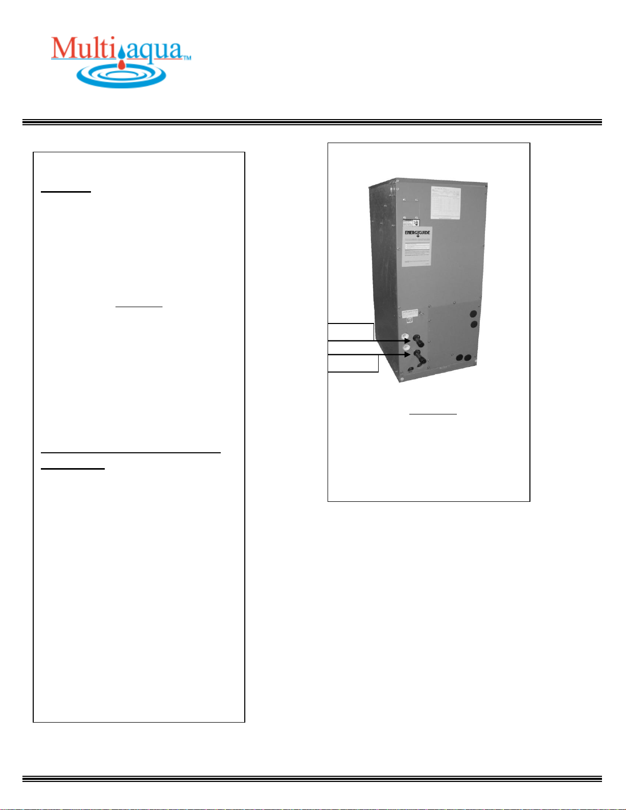
7. The fan coil comes with one
primary and one secondary
condensate drain connection per
configuration. Ensure when
connecting the field installed
condensate drain lines, the lower of
the two fan coil drain connections is
piped into the buildings condensate
removal method.
Figure 8 & 9
PRIMARY
DRAIN
SECONDARY
DRAIN
5
Page 6
INSTALLATION & OPERATING
MANUAL
CWA2 Chilled Water Air Handler with Electric Heat
18,000 – 60,000 BTUH
Figure 10
Figure 11
HORIZONTAL DISCHARGE
Figure 9
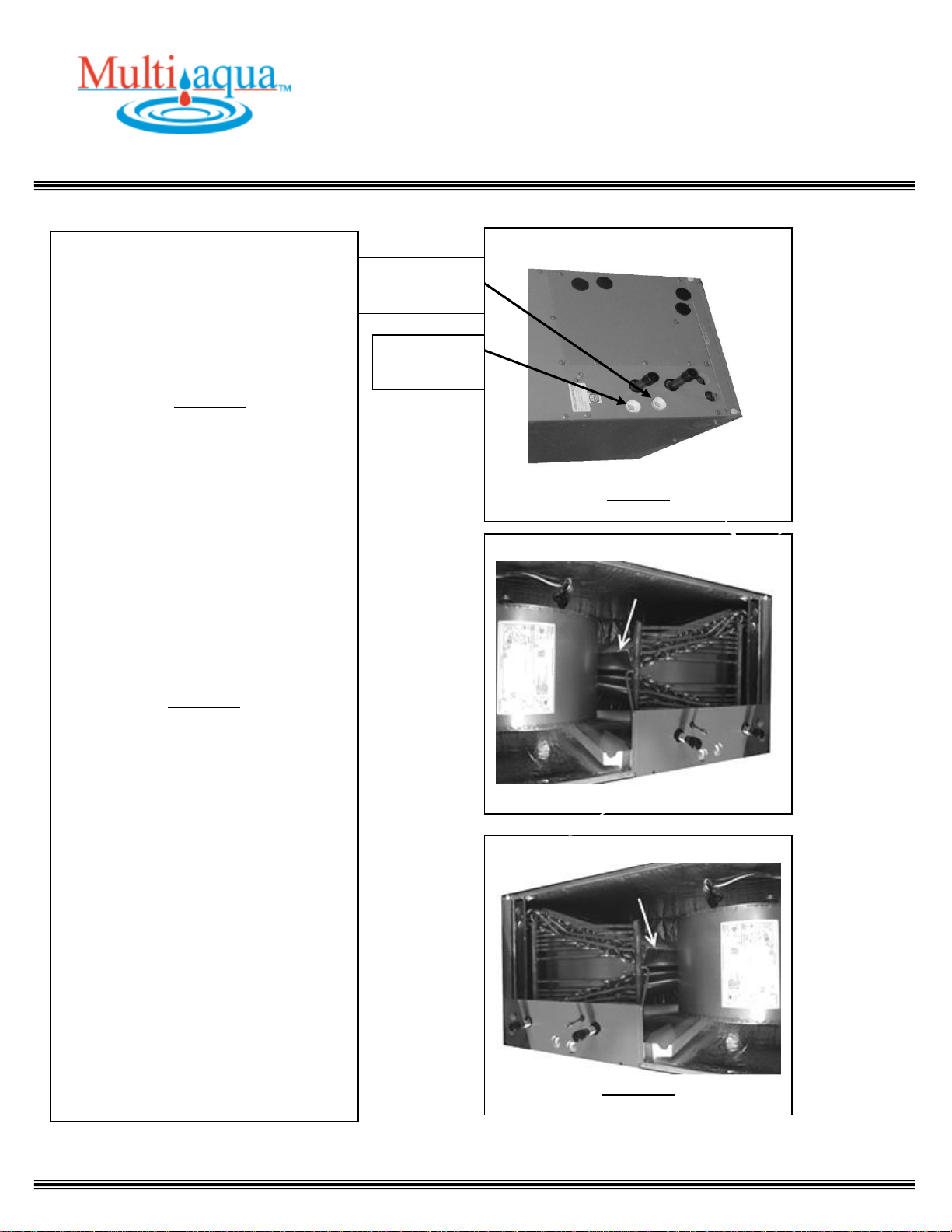
8. The “A” coil includes an L-shaped
piece of sheet metal with one leg of
the L covering the top length of one
coil slab; the other leg is
between/inside the two slabs.
Figure 10
When converting the unit to righthand horizontal discharge, the Lshaped piece of sheet metal should be
removed, re-positioned and installed
so that it covers the length of the top
coil slab. This will force any
condensate on the end of the top coil
slab to run down the inside leg before
dripping onto the lower slab. This
will also help to prevent any possible
condensate water blow off.
Figure 11
SECONDARY
DRAIN
PRIMARY
DRAIN
6
Page 7
INSTALLATION & OPERATING
MANUAL
CWA2 Chilled Water Air Handler with Electric Heat
18,000 – 60,000 BTUH
Figure 12
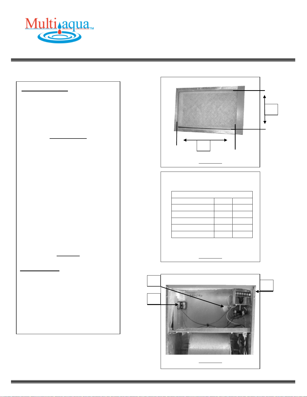
CWA2 Inlet Air Dimensions
A
B
18CWA2-00
15
17.5
24CWA2-00
15
17.5
36CWA2-00
15
17.5
48CWA2-00
19.25
22.25
60CWA2-00
19.25
22.25
Dimensions are in inches
Figure 13
Figure 14
ELECTRICAL
9. All duct work must be installed per
local and national codes. The return air
duct and the return air opening
provided in the fan coil must have the
same area.
Figure 12 & 13
All wiring must comply with local and
national codes. High and low voltage
terminal blocks are provided. An
electrical plug is provided for the field
installation of electric heat packages.
Knockouts are provided in the cabinet
for field wiring of the electrical. See
page 8 for electric heat package
installation instructions.
A = High Voltage terminal block.
B = Electric Heat Package Connection
Plug.
C = Low Voltage Terminal Block.
Figure 14
CONTROLS
A 24 VAC transformer, fan relay and
electric heat sequencer are provided
inside cabinet. All supplied controls are
wired onto the low voltage terminal
block.
B
A
A C B
7
Page 8
INSTALLATION & OPERATING
MANUAL
CWA2 Chilled Water Air Handler with Electric Heat
18,000 – 60,000 BTUH
8
Page 9
INSTALLATION & OPERATING
MANUAL
CWA2 Chilled Water Air Handler with Electric Heat
18,000 – 60,000 BTUH
Figure 15
PIPING
10. This fan coil is supplied with one
water coil that can be used for chilled
and/or hot water. The coil has one
dedicated water inlet and outlet. Ensure
that both lines are insulated according
to local and national building codes.
Figure 15
11. Condensate drains must be installed
with at least .25” of slope per foot away
from the fan coil. Since the drain pan is
located on the suction side of the
blower, a minimum trap of 1.5” must
be installed in the drain line for proper
drainage.
ROUTINE CHECK UP AND
SERVICE
This product is designed to provide
many years of dependable, trouble free
comfort when properly maintained.
Proper maintenance will consist of
routine filter cleanings/changes, biannual check-ups that include but not
limited to filter inspections, electric
heater inspections /cleaning of the
internal electrical and heat transfer
components by a qualified service
technician. Failure to provide periodic
check-ups and cleaning can result in
excessive operating cost and/or
equipment failure.
INLET
OUTLET
9
 Loading...