

INSTALLATION
&
OPERATING INSTRUCTIONS
CHILLED WATER FANCOIL
FLOOR/CEILING
CFFZ SERIES
INSTALLATION, START-UP AND SERVICE INSTRUCTIONS
FAN COIL UNIT SAFETY CONSIDERATIONS
Installation and servicing of air conditioning equipment can be hazardous due to system pressure
and electrical components. Only trained and qualied service personnel should install, repair or
service air conditioning equipment.
When working on air conditioning equipment, observe precautions in the literature and labels attached
to the unit and other safety precautions that may apply.
Follow all safety codes. Wear safety glasses and work gloves. Use quenching cloth for brazing
operations. Have a re extinguisher available for all brazing operations
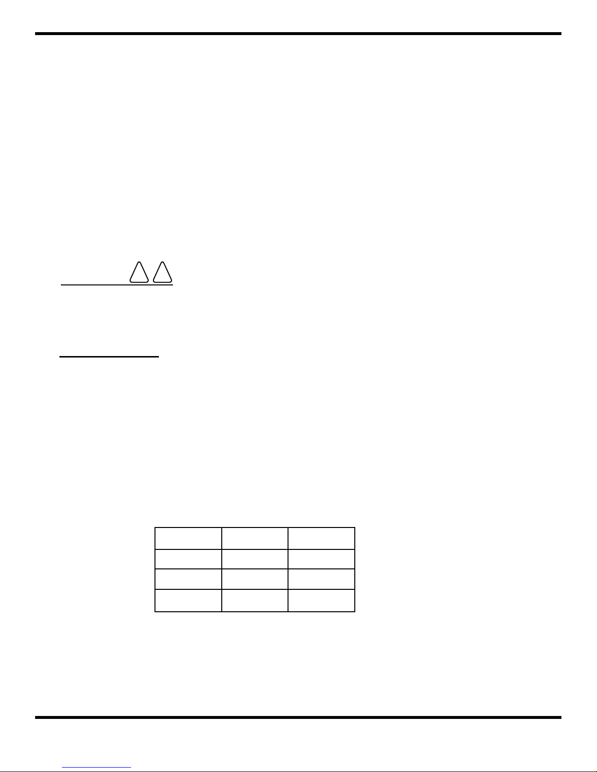
WARNING
Before preforming service or maintenance operations on the system, turn off the main power switches
to the indoor and outdoor unit. Electrical shock could cause personal injury.
! !
INITIAL CHECK
(1) The carton should not be removed from unit until reaching nal location to avoid damage.
(2) Inspect unit for shipping damage and le a claim with the transport agency if necessary.
(3) Check eld electrical works:
(a) Proper size of fuses and wire, correct wiring connections and grounding as specied
by the local electrical codes.
(b) Also check supply voltage, which must be within the limits shown on the nameplate.
(4) Check for a proper condensate ow.
(5) Be sure piping insulation is adequate.
(6) Conrm there are no obstructions to air ow for indoor and outdoor units. Also check for
sufcient clearances for servicing the unit.
MODEL A L
12-24 1024 927
30-36 1324 1227
48-60 1925 1828
1
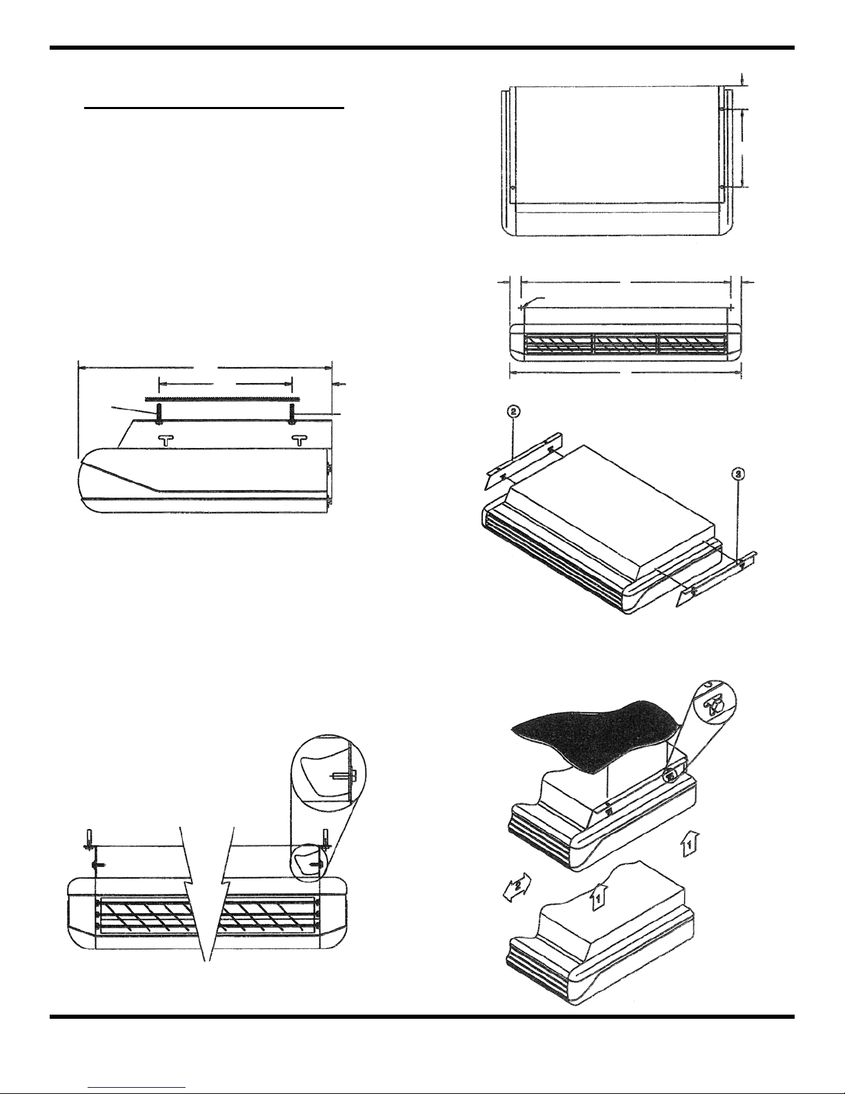
LOCATION & MOUNTING
105
(1) The unit should be installed for horizontal
and vertical discharge application only.
(2) Select position for unit and dene direction
of water pipe, drain pipe and electrical wire.
(3) Prepare mounting bolt for mounting unit
under ceiling or on a wall at the distance
dened in Fig. 1.
642
330
SIDE VIEW
105
48.5
TOP VIEW
L
BRACKET HANGER
A
FRONT VIEW
330
48.5
Fig. 1
(4) Remove unit from carton and carefully
place the unit into the position and tighten
the (4) bolts.
Fig. 2
Fig. 3
Fig. 4
2
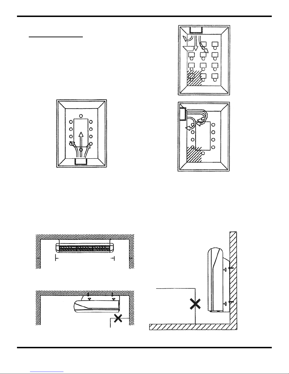
INSTALLATION
When mounting the indoor unit on the ceiling, oor
or wall, follow the instructions below:
(1) Select a location that permits the air current
to circulate evenly throughout the room.
O GOOD LOCATION EVENLY COOLED X BAD LOCATION OBLIQUE - LINE
Fig. 5
(2) Select a location that has enough service
space when the unit is mounted under the
ceiling.
300 MM300 MM
(3) Select a location that has enough service
space when the unit is mounted on the
oor/wall.
Fig. 7Fig. 6
3

WATER PIPING
(1) Connections to the indoor unit are
ared connections.
(i) Make ared joints for both water in
and water out lines.
(ii) Ensure tube and ttings are in line
with one another before tightening
nut to allow concentric seating of
tube into tting to prevent leakage.
(2) The water in and water out line should
run according to piping design as
shown in Fig. 8.
(3) Insulate water in and water out lines
adequately to prevent sweating.
(4) Use two spanners to connect the are
nut connection to the indoor unit.
See Fig. 9.
Fig. 9
(5) Water leak test:
Check all the brazed and are
connections for water leaks.
Note: The piping may also be run around
the rear of the unit so as to exit from the left
of the unit.
Fig. 8
4

CONDENSATE DRAIN
(1) Be sure the fancoil unit shall be
mounted in level on the ceiling as well
as on the oor/wall.
(2) Piping material:
(a) Soft Vinyl Chloride pipe
(b) Hard Vinyl Chloride (PVC)
(3) Connect the soft/hard Vinyl Chloride
pipe to the coupling. See Fig. 11.
(4) The indoor unit uses gravity to drain,
therefore, the piping outside the unit
should slope downward.
IMPORTANT - avoid draining as
(5)
shown in Fig. 12.
Fig. 11
Fig. 12
5

ELECTRICAL WIRING
(1) Be sure to supply power from a
dedicated supply circuit.
(2) Wiring should be made in accordance
with the applicable local codes.
(3) Ground both indoor and outdoor units.
(4) Check for correct correspondence in
terminal numbers.
1 RED
2 BLUE
3 BLACK
4 WHITE
5 YELLOW/GREEN
6 YELLOW
7 YELLOW
LOW
MEDIUM
HIGH
COMMON
GROUND
L SYNCHRONOUS MOTOR
N SYNCHRONOUS MOTOR
(5) Indoor wiring connections.
Fig. 13
Refer to wiring diagram for the wire
connections.
IMPORTANT
(a) Secure the cables with a cable
clamp after connecting them to
the terminal block.
(b) Power cabling can be executed by
authorized electricians only.
(c) The remote controller is located
inside the unit behind the return
air lter.
(6) Close the side panel.
(7) Mount the remote control mounting
bracket on the wall and x the remote
control onto the mounting bracket.
Connect the remote control to the fan
coil using the connecting cable
supplied.
6

AIR FLOW DIRECTION ADJUSTMENT
(1) To adjust the upward/downward direction of the air current, move the horizontal louvre.
Be careful to ensure the louvre is not positioned so as to completely cut off the airow
from the unit.
(2) To adjust the lateral direction of air current, use the air swing to adjust the direction.
FILTER REMOVAL FOR CLEANING
(1) Pull out the lter for cleaning. See Fig. 14.
Fig. 14
7

OPERATING MANUAL FOR TEMPERATURE CONTROLLER
POWER
The power button is used to switch on/off the
conditioner. When the power is switched to “on”, the air-
conditioner will operate according to the standard setting
(temperature=25 degree celsius.)
CONTROLLER TYPE WIRE
TEMPERATURE
The TEMP+ and TEMP- buttons are used to adjust
the temperature setting which can be set in the range of
15-40°C. When the button is pressed, the control unit will
display the setting temperature (blinking), instead of the
room temperature. After setting is complete, it will resume
display of the room temperature within 4 seconds.
FAN
Fan speed (High, Medium, Low) can be altered using
the FAN button.
AUTO START
When the air-conditioner is “off” you can program
the unit to start by pressing the TIMER button. When you
press the TIMER button, the gure will change from “0” to
1 to 2 and up to 12 hours. Once you have set the timer, the
CONTROLLER TYPE WIRELESS
controller will count down until the time is “0”, and then the
controller will automatically turn on the air-conditioner.
AUTO STOP
When the air conditioner is “on” you can program the unit to stop by pressing the TIMER button. When
you press the timer button, the gure will change from “0” to 1 to 2 up to 12 hours. Once you have set the
TIMER, the controller will count down until the time is “0” and then automatically turn off the air-conditioner.
MODE
This control allows you to operate the unit in different ways: Cool, Fan and Heat. When the control
operates in Cool mode, the COOL LED lights. When the control operates in Heat mode, the HEAT LED lights.
When the control operates in Fan mode, both the COOL and HEAT LEDs are off.
SWEEP
Switch the swing motor on and off. When the sweep is “on” it will cause the ari stream from the unit to
sweep back and forth.
LV
The LV button can be used to adjust the direction of air stream coming from the unit.
8

WIRING DIAGRAM FOR WIRELESS CONTROL
24V TO
WATER CONTROL VALVE
TERMINAL BLOCK
SYNCHRONOUS
MOTOR
TEMPERATURE
SENSOR
TRANSFORMER
WH = WHITE
YL = YELLOW
RD = RED
BK = BLACK
BR = BROWN
BL = BLUE
RECEIVER
REMOTE
DIAGRAM FOR COOL ONLY SYSTEM
CAUTION : IF 220V CONTRACTOR IS USED, THE 24V TRANSFORMER MUST BE TAKEN OUT.
9

-- NOTES --
10

Tel: (954) 431-1300 • Fax: (954) 431-1303 • email: support@multiaqua.com
MULTIAQUA, INC.
2701 S.W. 145 AVENUE, SUITE #220
MIRAMAR, FLORIDA 33027 U.S.A.
www.multiaqua.com
 Loading...