

Page 1
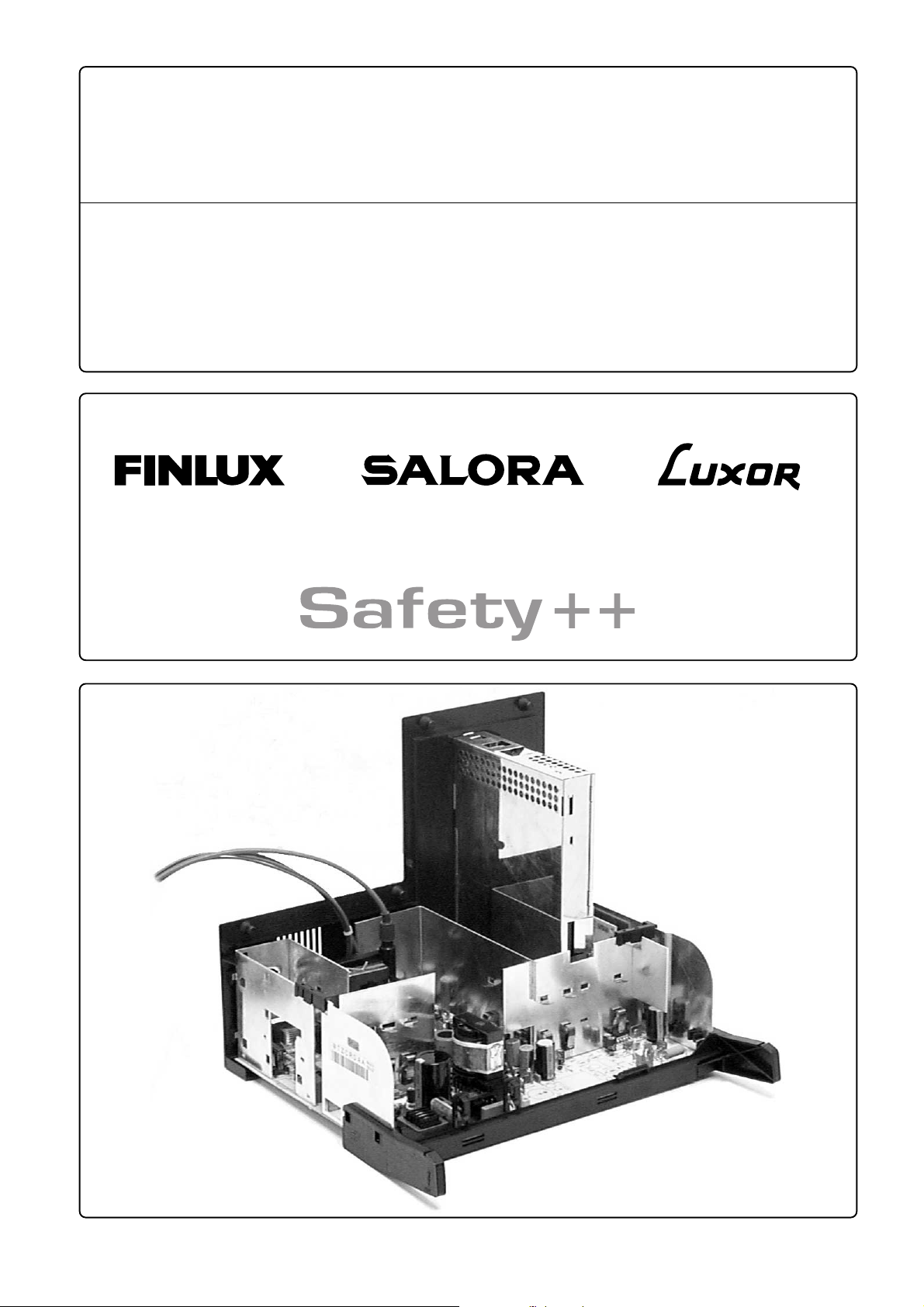
MULTI CONCEPT 2A
9
TZ CHASSIS
(100 Hz, 16:9)
Supplement to service manual
G
F Complément du manuel de service
D Ergänzung zum Service-Manual
I Supplemento al manuale di servizio
S Bilaga till serviceanvisning
72X200 MC++ 100Hz
82X210 MC++ 100Hz
82X200 MC++ 100Hz
28MCW210 Opera++ 100Hz
32MCW210 Opera++ 100Hz
32MCW220 Opera++ 100Hz
TV
04/2002
66119670
66119688
72TF102++ 100Hz
82TF102++ 100Hz
82TF202++ 100Hz
82SF10 100Hz
66117306
Page 2

10
G Contents
Repair instructions .....................................................................................................................................................................1
Technical data .............................................................................................................................................................................3
Variable components ................................................................................................................................................................. 4
Mechanical parts ........................................................................................................................................................................5
D Inhaltsverzeichnis
Reparatur-Anweisung ................................................................................................................................................................1
Technische Daten ....................................................................................................................................................................... 3
Röhrenabhängige Bauteile ........................................................................................................................................................4
Mechanische Bauteile ................................................................................................................................................................5
S Innehåll
Reparationsinstruktioner ........................................................................................................................................................... 1
Tekniska data .............................................................................................................................................................................. 3
Komponentskillnader ................................................................................................................................................................. 4
Mekaniska delar..........................................................................................................................................................................5
F Contenu
Instructions de reparation ......................................................................................................................................................... 2
Données techniques...................................................................................................................................................................3
Composants variables ............................................................................................................................................................... 4
Parties mécaniques ....................................................................................................................................................................5
I Indice
Istruzioni di servizio ................................................................................................................................................................... 2
Dati tecnici .................................................................................................................................................................................. 3
Componenti che differiscono ....................................................................................................................................................4
Parti meccaniche ........................................................................................................................................................................5
Copyright © 2002 by Turku TV Operations Ltd. All Rights Reserved. www.turkutv.com
Page 3

G Repair instructions
Service and repair work must be performed only in
accordance with the existing safety regulations!
Where a high current or a mechanical stress exists solder
connections have been strengthened by using eyelets.
Such a connection must not be left without an eyelet.
Wiring has an effect on safety and EMC (ElectroMagnetic Compatibility). Therefore wires must be
maintained in their original positions.
X-RAY REGULATIONS:
The picture tube type and the maximum permissible
high-voltage ensure that the X-ray intensity of the
receiver remains far below the permissible value. The
high-voltage must not exceed the value mentioned on
the type label. The high voltage is within the permissible
limits when the operating voltage (U1) of the horizontal
deflection stage is accurate. Refer to the section
“Service adjustments”.
D Reparatur-Anweisung
Service- und Reparaturarbeiten dürfen nur in
Übereinstimmung mit den gültigen
Sicherheitsbestimmungen durchgeführt werden!
Bei bestehendem hohen Stromwerten oder
mechanischer Beanspruchung müssen Lötverbindungen
durch Ösen verstärkt werden. Eine derartige Verbindung
darf nicht ohne Öse ausgeführt werden.
Die Verdrahtung hat Einfluß auf die Sicherheit und die
elektromagnetische Verträglichkeit. Daher muß die
ursprüngliche Anordnung der Verdrahtung erhalten
bleiben.
1
ESD Warning
The receiver contains components that are sensitive to
electrostatic discharge (ESD). Any servicing or repair
work must be done in an environment where the
components will not be subjected to ESD. Use a special
grounding device!
Surface-Mounted Device (SMD)
SMD´s are glued and soldered. In order not to damage
the P.C.B e.g. when replacing ICs and similar
components with many soldering points, special tools
are required when servicing SMD´s.
Changes
The manufacturer reserves the right to change the
design and specification without prior notice.
EGB-Warnung
Das Fernsehgerät enthält Bauteile, die empfindlich auf
elektrostatische Entladung reagieren. Alle Service- oder
Reparaturarbeiten sind in einer Umgebung
durchzuführen, in der die Bauteile nicht elektrostatischer
Entladung ausgesetzt sind. Verwenden Sie eine spezielle
Erdungsvorrichtung!
SMD-Bauelement
Die SMD’s sind geklebt und verlötet. Es sind spezielle
Werkzeuge erforderlich, damit bei Austausch von ICs und
ähnlichen Bauteilen mit vielen Lötpunkten die
Leiterplatte nicht beschädigt wird.
RÖNTGENVERORDNUNG
Der Bildröhrentyp und die maximal zulässige
Hochspannung stellen sicher, daß die Intensität der
Röntgenstrahlen des Fernsehgerätes weit unter dem
zulässigen Wert bleibt. Die Hochspannung darf nicht den
auf dem Typenschild befindlichen Wert überschreiten.
Die Hochspannung liegt im zulässigen Bereich, wenn die
Betriebsspannung (U1) der Horizontal-Ablenkstufe genau
eingehalten wird. Siehe auch Abschnitt
“Service-Einstellungen“.
S Reparationsinstruktioner
Service och reparationer måste utföras med hänsyn till
gällande säkerhetföreskrifter.
Lödningar som utsätts för höga strömmar eller mekanisk
belastning är förstärkta med genomföringshylsor. Dessa
anslutningar får inte lämnas utan dessa hylsor.
Kabeldragningen har inverkan på säkerhet och EMC
(Elektromagnetisk kompabilitet). Därför måste kablarna
monteras i deras originalposition.
RÖNTGENSTRÅLNING:
Bildrörstyp och begränsning av maximum högspänning
garanterar att mottagarens röntgenstrålning hålls långt
under tillåten nivå. Högspänningen får inte överskrida
värdet som visas på typetiketten. Högspänningen är
inom tillåtna gränser när horisontalavlänkningens
drivspänning (U1) är rätt inställd. Se avsnitt
“Service-inställningar”.
Änderungen
Der Hersteller behält sich das Recht vor, Änderungen in
Bauart und Ausführung ohne vorherige Ankündigung
durchzuführen.
ESD varning
Mottagaren har komponenter som är känsliga för
elektrostatisk urladdning (ESD). All servicearbete måste
göras så att dessa komponenter inte utsätts för ESD.
Använd en speciell jordninganordning.
Ytmonterade komponenter (SMD)
SMD-komponenterna är både limmade och fastlödda.
För att inte skada kretskortet när man t.ex. byter IC:n
med många lödpunkter bör man använda specialverktyg.
Ändringar
Tillverkaren reserverar rätt till att ändra design och
spesifikationer utan skild meddelande.
Page 4
2
F Instructions de reparation
Les opérations de maintenance et les réparations ne
doivent être effectuées qu’en conformité avec les règles
de sécurité en vigueur !
Les connexions par soudure doivent être renforcées par
des oeillets lorsqu’elles sont soumises à une forte
intensité de courant ou à des contraintes mécaniques
importantes. Ces connexions doivent toujours être
renforcées par ce moyen.
Le câblage est un facteur important pour la sécurité et
les perturbations électromagnétiques. En conséquence,
maintenez les câbles dans leur position initiale.
REGLEMENTATION RELATIVE AUX RAYONS X :
Votre tube cathodique et la tension maximale autorisée
garantissent le maintien des rayons X bien en decà du
niveau autorisé. La tension la plus élevée ne doit pas
dépasser la valeur indiquée sur la plaquette signalétique
de l’appareil. Cette tension reste dans la fourchette
autorisée lorsque la tension de service (U1) d’étage de
déflexion horizontale est précise. Reportez-vous à la
section “Réglages de service”.
Avertissement concernant les décharges
électrostatiques
Le récepteur contient des composants sensibles aux
décharges électrostatiques (DES). Les opérations de
maintenance et les réparations doivent être effectuées
dans un environnement n’exposant pas les composants
à ces décharges. Pour cela, utilisez un dispositif de mise
à la terre spécial !
Composants montés en surface (SMD)
Ces composants sont collés et soudés. Pour ne pas
endommager les cartes à circuits imprimés, par exemple
lors du remplacement de circuits et de composants
similaires ayant de nombreux points de soudure, vous
devez utiliser des outils spécifiques lorsque vous
effectuez la maintenance des appareils montés en
surface.
Modifications
Le fabricant se réserve le droit de modifier la conception
et les caractéristiques de son produit sans avis préalable.
I Istruzioni di servizio
Interventi di assistenza tecnica e riparazione devono
essere eseguiti nel più assoluto rispetto delle norme di
sicurezza vigenti!
Qualora esistano condizioni di elevati livelli di corrente e
stress meccanici le connessioni saldate sono state
potenziate tramite occhielli. Questo tipo di connessioni
non devono essere lasciate senza occhiello.
Le connessioni influiscono sulla sicurezza e gli standard
EMC (Electro-Magnetic Compatibility). Pertanto, i fili
elettrici devono essere mantenuti nelle loro posizioni
originarie.
NORME SUI RAGGI X:
Il tipo di tubo catodico unitamente all’uso del massimo
livello di alta tensione consentito fanno sì che l’intensità
dei raggi X del ricevitore rimanga molto al di sotto del
valore consentito. L’alta tensione non deve superare il
valore indicato sull’apposita etichetta. L’alta tensione
rientra nei limiti consentiti quando la tensione operativa
(U1) del livello di deflessione orizzontale è corretta. Fare
riferimento alla sezione “Regolazioni di servizio”.
Avvertenza ESD (scariche elettrostatiche)
Il ricevitore contiene componenti sensibili all’elettricità
statica. Qualsiasi intervento di assistenza tecnica o
riparazione deve essere eseguito in un ambiente in cui i
componenti non possano essere soggetti a scariche
elettrostatiche (ESD). A tal fine, usare uno specifico
dispositivo di messa a terra!
Dispositivi SMD (Surface-Mounted Device)
I dispositivi SMD sono incollati e saldati. Sono necessari
strumenti specifici per non danneggiare la scheda PCB
quando si sostituiscono circuiti integrati (IC) e simili
componenti con molti punti di saldatura.
Modifiche
La Casa costruttrice si riserva il diritto di modificare il
design e le specifiche senza preavviso.
Page 5

3
Hz
V, 50
W (normal)
PAL/SECAM B, G
PAL/SECAM B, G, D, K, K1, L, L’, I
3.58 MHz via scart
4.43 MHz via RF / scart
195...264
130
1)
2)
Dati tecnici
Sistema
Televisori multistandard
NTSC
Tensione di alimentazione
Consumo energetico
1)
2)
MHz
Ω
Ω
W/8
W
< 1
In standby
W/16
48.25...855.25
2 x 10
14
1)
Campo di frequenza
Potenza audio (RMS)
Subwoofer
Connessioni sul pannello
frontale
1)
(RMS)
Ω
V
mm
V/75
Ω, 3.5
(SVHS)
32...600
Audio in: 0...2
Video in: 1
Y/C in
Cuffia
Audio/Video
kΩ
)
1)
kΩ
Ω
Ω (E1, E3
V/RL min. 10
V/75
V/RIN =1
Audio in: 0...2
Connessioni sul pannello
posteriore
Audio/Video
(E2)
V/75
Ω
Audio out: 0...2
Video in/out: 1
RGB in: 0.7
Y/C in (SVHS)
75
Antenna
kΩ (RCA)
0...2 V/10
Uscita audio
sinistra/destra
(RCA)
Hz
Hz
kΩ 20...180Hz (RMS)
640 x 480 60
640 x 400 70
0...2 V/10
1)
subwoofer
Ingresso VGA
1)
(RCA)
Hz
Hz
V (RMS)
640 x 350 70
720 x 400 70
0...2
1)
Ingresso audio VGA
1)
kg
kg
kg
mm / 48,5
mm / 39,5
mm / 56,5
915 x 568 x 545
722 x 538 x 537
798 x 569 x 595
3)
Circa.
e del tubo catodico.
Non in tutti i modelli.
Dimensioni
(Larghezza x profondità x altezza / peso)
32” R3 16:9
28” X6/X8 16:9
32” X6/X8 16:9
Le specifiche sono soggette
3)
A seconda dei moduli opzione
a cambiamenti.
1)
2)
3)
Données téchniques
Systéme
Téléviseurs multinormes
NTSC
Alimentation
Consommation
En mode veille
Gamme de fréquences
Sortie sonore (RMS)
Subwoofer
2)
1)
1)
Tekniska data
Norm
Multinorm-TV
NTSC
Nätanslutning
Effektförbrukning
I beredskapsläget
Frekvensområde
Ljudeffekt (RMS)
Subwoofer
2)
1)
Technische Daten
Norm
Multinorm
NTSC
Netzanschluß
Leistungsaufnahme
In Bereitschaft
1)
Frequenzbereich
Tonendstufe (RMS)
Subwoofer
Connexions sur le panneau
avant
Ecouteurs
Audio/Vidéo
Anslutningar på framsidan
Hörlurar
Audio/Video
Anschlüsse an der
Vorderseite
Kopfhöreranschluß
Audio/Video
Connexions sur le panneau
arrière
Audio/Vidéo
Anslutningar på baksidan
Audio/Video
Anschlüsse an der Rückseite
Audio/Video
Antenne
Sortie audio
gauche/droite
subwoofer
Entrée VGA
1)
Antenn
Ljudutgångar
vänster/höger
subwoofer
VGA ingång
1)
Antennenanschluß
Audio Ausgang
links/rechts
subwoofer
VGA Eingang
Entrée audio VGA
Mesurer
(Largeur x profondeur x hauteur / poids)
32” R3 16:9
28” X6/X8 16:9
32” X6/X8 16:9
Les spécifications peuvent
être modifiées sans préavis.
1)
2)
1)
3)
Inte i alla modeller.2)Varierar beroende på modul-
Pas sur tous les modèles.
VGA ljudingång
Mått
(Bredd x djup x höjd / vikt)
32” R3 16:9
28” X6/X8 16:9
32” X6/X8 16:9
Rätt till ändringar
förbehålles.
1)
1)
3)
Nicht in allen Modellen.
VGA Audio-Eingang
Maße
(Weite x Tiefe x Höhe / Gewicht)
32” R3 16:9
28” X6/X8 16:9
32” X6/X8 16:9
Änderungen vorbehalten
1)
nels et du tube cathodique.
Approximativement.
Dépend des modules option-
3)
Cirka.
uppsättning och bildrör.
3)
Ungefähr.
Abhängig von Options-
modulen und Bildröhre.
2)
3)
2)
1)
Technical data
System
Multinorm
NTSC
Mains power
Consumption
In stand-by
1)
Frequency range
Sound output (RMS)
Subwoofer
Connections on the front
panel
Headphones
Audio/Video
Connections on the rear
panel
Audio/Video
Antenna
Audio output
1)
right/left
subwoofer
VGA input
1)
3)
VGA audio input
Dimensions
(Width x depth x height / weight)
32” R3 16:9
28” X6/X8 16:9
32” X6/X8 16:9
Specifications are subject to
and picture tube.
Approximately.
Not in all models.
Depends on option modules
change.
1)
2)
3)
Page 6

4
G Variable components D Röhrenabhängige Bauteile S Komponentskillnader
F Composants variables I Componenti che differiscono
Note! Hinweis! Obs! Remarque ! Nota!
w Safety components in accordance with existing safety regulations. These components must be replaced only with
original parts.
w Sicherheitsbauteil im Sinn der Sicherheitsbestimmung. Diese Teile dürfen nur durch Originalteile ersetzt werden.
w Skyddskomponenter. Dessa komponenter får endast ersättas med original reservdelar.
w Composant de sécurité conformément aux règlementations de sécurité. Ces composants doivent être uniquement remplacés
par des pièces d'origines.
w Componenti di sicurezza ai sensi del regolamento di sicurezza. Queste componenti devono venir sostituiteunicamente con
parti originali.
* Version components
* Röhrenabhängige Bauteile
* Komponentskillnad
* Composants variables
* Componenti che differiscono
Marketing code Production code Chassis SW version Design AV module Tuner Picture tube type / Order no.
72X200 MC++ 100 Hz TZ72X8RFFCH TZVRAAA TZAE16.0 28” X8 AVFCBAA 4046 FM5 28” Phi 16:9 W66ERF041X044* 43642845
82X210 MC++ 100 Hz TZ82X8RFACH TZWRDAA
82X200 MC++ 100 Hz TZ82X8RFFCH TZZRAAA TZAE16.0 32” X8 AVFCBAA 4046 FM5 32” Phi 16:9 W76ERF041X044* 43643211
TZAE16
.0 32” X8 AVCCBAA 4046 FM5 32” Phi 16:9 W76ERF041X044* 43643211
Marketing code Production code Chassis SW version Design AV module Tuner Picture tube type / Order no.
72TF102++ 100 Hz TZ72X6ELFCH TZVEAAA TZAE16.0 28” X6 AVFCBAA 4006 FH5 28” Phi 16:9 W66ERF041X044* 43642845
82TF102++ 100 Hz TZ82X6ELFCH TZZEAAA TZAE16.0 32” X6 AVFCBAA 4006 FH5
82TF202++ 100 Hz TZ82X6RLACH TZWRDAA TZAE16.0 32” X6 AVCCBAA 4046 FM5 32” Phi 16:9 W76ERF041X044* 43643211
82SF10 100Hz TZ82R3ELFBP TZLEAAA TZAE16.0 32” R3 AVFCBAA 4006 FH5 32” Phi 16:9 W76ESF031X44 43643206
Marketing code Production code Chassis SW version Design AV module Tuner Picture tube type / Order no.
28MCW210 Opera++ 100 Hz TZ72X6RSFCH TZVRAAA TZAE16.0 28” X6 AVFCBAA
32MCW210 Opera++ 100 Hz TZ82X6ESDCH TZZEAAA TZAE16.0 32” X6 AVECBAA
32MCW220 Opera++ 100 Hz TZ82X6RSACH TZWRDAA TZAE16.0 32” X6 AVCCBAA
* PLEASE NOTE:
DO NOT ADJUST THE POTENTIOMETERS ON THE CONVERGENCE CORRECTION MODULE OF THE PHILIPS TRUE FLAT PICTURE TUBE (TYPES W66ERF & W76ERF).
ADJUSTMENT OF THESE POTENTIOMETERS WILL VOID THE WARRANTY FOR THE PICTURE TUBE.
* BEACHTEN SIE BITTE:
DIE POTENTIOMETER DES KONVERGENZ-KORREKTIONSMODULES DER PHILIPS “TRUE FLAT”-BILDRÖHRE (TYPEN W66ERF & W76ERF) DÜRFEN NICHT VERSTELLT WERDEN.
BEI VERSTELLUNG DIESER POTENTIOMETER ERLÖSCHEN DIE GARANTIEANSPRÜCHE AUF DIE BILDRÖHRE.
* OBSERVERA!
RÖR INTE POTENTIOMETRARNA PÅ PHILIPS TRUE FLAT BILDRÖRETS (TYP W66ERF & W76ERF) KOVERGENSMODUL.
BILDRÖRETS GARANTI UPPHÖR OM INSTÄLLNINGEN ÄNDRAS PÅ DESSA POTENTIOMETRAR.
* REMARQUE :
NE REGLEZ PAS LES POTENTIOMETRES SUR LE MODULE DE CORRECTION DE LA CONVERGENCE DE VOTRE TUBE EXTRA-PLAT PHILIPS (TYPES W66ERF ET W76ERF).
LE REGLAGE DE CES POTENTIOMETRES ANNULE LA GARANTIE DU TUBE CATHODIQUE.
* NOTA:
NON REGOLARE I POTENZIOMETRI SUL MODULO DI CORREZIONE DELLA CONVERGENZA DEL CINESCOPIO PHILIPS TRUE FLAT (MODELLI W66ERF E W76ERF).
MODIFICANDO LE IMPOSTAZIONI DI TALI POTENZIOMETRI VIENE RESA NULLA LA GARANZIA INERENTE AL CINESCOPIO.
4046 FM5
4006 FH5 32” Phi 16:9 W76ERF041X044* 43643211
4046 FM5 32” Phi 16:9 W76ERF041X044* 43643211
32” Phi 16:9 W76ERF041X044* 43643211
28” Phi 16:9 W66ERF041X044* 43642845
Page 7

Mechanical parts, chassis
5
Item Description Order no. Item Description Order no.
MODULES
1 MAIN BOARD TZ*****
(see section variable components, page 4)
2 SIGNAL MODULE (AV100) AV*****
(see section variable components, page 4)
METAL PARTS
3 HEAT SINK 1 84830830
4 HEAT SINK 2 84830910
5 HEAT SINK 3 84830920
6 HEAT SINK 4b 84830970
7 HEAT SINK 5 84830900
8 SIGNAL BOX BOTTOM 84860590
9 SIGNAL BOX LID 84860600
16 AV MODULE BRACKET 84481920
PLASTIC PARTS
10 COVER PLATE FOR CONNECTOR AREA
A (3 x SCART, VGA + AUDIO IN) 84488800
- Finlux 82X210 MC++ 100 Hz
- Luxor 82TF202++ 100Hz
- Salora 32MCW220 Opera ++ 100Hz
B (3 x SCART, NO VGA + AUDIO IN) 84401100
- Finlux 72X200 MC++ 100Hz
- Finlux 82X200 MC++ 100Hz
- Luxor 72TF102++ 100Hz
- Luxor 82TF102++ 100Hz
- Luxor 82SF10 100Hz
- Salora 28MCW210 Opera ++ 100Hz
- Salora 32MCW210 Opera ++ 100Hz
11 WIRE HOLDER 84486070
12 CHASSIS HOLDER LEFT 80409535
13 CHASSIS HOLDER RIGHT 80409559
14 CONNECTING PIECE 1-3 (ONLY NO. 3 USED) 84488881
15 CONNECTING PLATE 28" 84488470
SPRINGS, SCREWS
18 HEAT SINK SPRING 79400021
19 PT-SCREW 2.9x9.5 (2 AUDIO OUT, 1 AUDIO IN) 78360002
C (2 x SCART, NO VGA + AUDIO IN) 84405110
Page 8

6
Mechanical parts 32” R3
36
35
24
27
32
21
20
31
28
29
27
30
6
1
23
7
5
9
21
34
26
25
19
21
17
22
33
11
10
8
3
2
15
13
Torque:
16
4,5 Nm ±10%
12
18
Item Description Order no. Item Description Order no.
1 w CABINET 32R3 SILVER 85101070
2 PT-SCREW KB40x8 FOR LOUDSPEAKER WC0368
3 LOUDSPEAKER 57x126mm 8Ω 10W 43120022
4 CHASSIS HOLDER 84488830
5 FOOT PAD 14.6mm 80424027
6 w MAINS CABLE 2.25m 70003769
7 BADGE LUXOR UA1249
8 w PICTURE TUBE 32” Phi 16:9 W76ESF031X44 43643206
9 DEGAUSSING COIL HOLDER 84488950
10 w DEGAUSSING COIL 45820028
11 WIRE TIE 2.5x100mm 54040164
12 GROUNDING WIRE FOR PICTURE TUBE 96010091
13 GROUNDING SPRING 81401082
15 PICTURE TUBE HOLDER 84480810
16 PT-SCREW 7X40 FOR PICTURE TUBE WC2027
17 WIRE TIE 190mm 65221205
18 w CHASSIS TZ*****
(see section variable components, page 4)
19 w CRT MODULE HH150
20 w BACK COVER 32R3 MDB 84303660
21 PT-SCREW KB40x10 WC0353
22 FELT PAD 80440385
23 CONTROL UNIT SY101
24 CONTROL UNIT FRAME 84460980
25 CONTROL UNIT MODULE FC101
26 PUSH BUTTON 63157040
27 PT-SCREW KB30x8 WC0371
28 COMPRESSION SPRING UC3051
29 MAINS BUTTON 84680500
30 FLAP LOCK 80413473
31 FLAP 84501470
32 w FIRE BARRIER 84860450
33 w COMPENSATION COIL 220mm 45820005
34 MODULE SUPPORT 81408167
35 w COVER FOR CAMERA CONNECTOR 84488890
36 w MAINS SWITCH 250V 6/120A 41210011
LOUDSPEAKERS WIRE BUNDLE 96010145
EXTENSION FOR MAINS BUTTON 84680760
w WIRE BUNDLE H-DEFLECTION 96010059
w WIRE BUNDLE V-DEFLECTION 96010164
w FOCUS CABLE 410mm 96010220
w FOCUS CABLE 1,2 410mm 96010230
w SCREEN CABLE 460mm 96010240
w ANODE CABLE 630mm + CHIMNEY 96008869
SIGNAL MODULE (AV100) AV*****
(see section variable components, page 4)
AUDIO LINE OUTPUT MODULE TA100
TUNER 4006 FH5 58231063
Page 9

Mechanical parts 28” X6 / X8
25
26
27
24
19
18
14
29
9
8
6
7
46
13
16
17
21
23
20
31
30
32
22
40
41
36
45
35
34
37
31
33
38
39 X6
39 X8
43 X8
44 X8
1
28
2
4
3
12
43 X6
42
44 X6
10
15
Torque:
4,5 Nm ±10%
5
11
47
7
Item Description Order no. Item Description Order no.
1 w CABINET 28X6/8 SILVER
2 GRILL 28 SILVER 84603580
3 LOUDSPEAKER MOUNTING PLATE 84401090
4 LOUDSPEAKER 70x130mm 8Ω 43120005
5 PT-SCREW KB40x8 WC0368
6 CROSSOVER NETWORK MODULE AJ104
7 PT-SCREW KB40x8 WC0368
8 CHASSIS BRACKET 84488820
9 CHASSIS HOLDER 84488440
10 FOOT PAD 14.6mm 80424027
11 PT-SCREW KB40x10 WC0353
12* BAGDE FINLUX 84701620
12* BAGDE LUXOR UA1249
12* BAGDE SALORA UA1245
13 w PT 28” Phi 16:9 W66ERF041X044 TF 100Hz 43642845
14 DEGAUSSING COIL HOLDER 84488950
15 PT-SCREW K70x30 FOR PICTURE TUBE 62034039
16 GROUNDING SPRING 81401082
17 GROUNDING WIRE FOR PICTURE TUBE 96010090
18 w DEGAUSSING COIL 45820030
19 WIRE TIE 2.5x100mm 54040164
20 w COMPENSATION COIL 220mm 45820005
21 WIRE TIE 190mm 65221205
22 PICTURE TUBE HOLDER 84480810
23 w CRT MODULE HH140
24*w CHASSIS TZ*****
(see section variable components, page 4)
25 PT-SCREW KB40x20 WC0354
26 w BACK COVER 28 X6/8 LIGHT GREY 84303780
27 PT-SCREW KB40x20 FOR BACK COVER WC0354
28* CONTROL UNIT X6 SY112
28* CONTROL UNIT X8 SY113
29 PT-SCREW KB30x8 WC0371
8201700A
30 CONTROL UNIT MODULE FC101
31 PT-SCREW KB30x8 WC0371
32 MODULE SUPPORT 81408167
33 PUSH BUTTON 63157040
34 w MAINS SWITCH 250V 6/120A 41210011
35 w COVER FOR CAMERA CONNECTOR 84488890
36 FLAP LOCK 80413473
37 CONTROL UNIT FRAME 84461180
38 COMPRESSION SPRING UC3051
39* MAINS BUTTON X6 84680770
39* MAINS BUTTON X8 84680780
40 DAMPER 84488870
41 PT-SCREW KB25x8 78360040
42 FLAP SAFETY++ 84501610
43* LENS LEFT SIDE X6 84553550
43* LENS LEFT SIDE X8 84553560
44* LENS RIGHT SIDE X6 84553590
44* LENS RIGHT SIDE X8 84553600
45 w MAINS CABLE 2.25m 70003769
46 GROUNDING WIRE FOR GRILL 96010210
47 FELT PAD 80440385
EXTENSION FOR MAINS BUTTON 84680760
LOUDSPEAKERS WIRE BUNDLE 96010087
w WIRE BUNDLE H-DEFLECTION 96010059
w WIRE BUNDLE V-DEFLECTION 96010203
w FOCUS CABLE 410mm 96010220
w FOCUS CABLE 1,2 410mm 96010230
w SCREEN CABLE 460mm 96010240
w ANODE CABLE 630mm + CHIMNEY 96008869
SIGNAL MODULE (AV100) AV*****
(see section variable components, page 4)
AUDIO LINE OUTPUT MODULE TA100
* TUNER 4046 FM5 58231061
* TUNER 4006 FH5 58231063
Page 10

8
Mechanical parts 32” X6 / X8
54
50
32
31
35
11
37
36
34 X6
29
32
33
34 X8
7
30
53
49
42
43
21
48
46
41
24
56
47
26
51
26
44
45
25
18
19
Torque:
22
4,5 Nm ±10%
16
23
15
39 X8
39 X6
1
28
55
40 X8
4
2
3
38
40 X6
55
8
12
10
7
9
6
13
14
52
5
17
Item Description Order no. Item Description Order no.
1 w CABINET 32X6/8 SILVER
2 GRILL SILVER 84603570
3 LOUDSPEAKER MOUNTING PLATE 84401090
4 LOUDSPEAKER 70x130mm 8Ω 43120005
5 TWEETER 51x51mm 8Ω 33004365
6 CROSSOVER NETWORK MODULE AJ101
7 PT-SCREW KB40x10 WC0353
8 CHASSIS BRACKET 84488820
9 CHASSIS HOLDER 84488440
10 FOOT PAD 14.6mm 80424027
11 w MAINS CABLE 2.25m 70003769
12* BAGDE FINLUX 84701620
12* BAGDE LUXOR UA1249
12* BAGDE SALORA UA1245
13*w PICTURE TUBE
(see section variable components, page 4)
14 DEGAUSSING COIL HOLDER 84488950
15 w DEGAUSSING COIL 45820029
16 WIRE TIE 2.5x100mm 54040164
17 GROUNDING WIRE FOR GRILL 96010210
18 GROUNDING WIRE FOR PICTURE TUBE 96010091
19 GROUNDING SPRING 81401082
21 PICTURE TUBE HOLDER 84480810
22 PT-SCREW 7x40 FOR PICTURE TUBE WC2027
23*w CHASSIS TZ*****
(see section variable components, page 4)
24 w CRT MODULE HH140
25 w BACK COVER 32 X6/8 LIGHT GREY 84303790
26 PT-SCREW KB40x20 WC0354
28* CONTROL UNIT X6 SY112
28* CONTROL UNIT X8 SY113
29 CONTROL UNIT FRAME 84461180
30 CONTROL UNIT MODULE FC101
31 PUSH BUTTON 63157040
32 PT-SCREW KB30x8 WC0371
33 COMPRESSION SPRING UC3051
34* MAINS BUTTON X6 84680770
34* MAINS BUTTON X8 84680780
8201710A
35 FLAP LOCK 80413473
36 DAMPER 84488870
37 PT-SCREW KB25x8 78360040
38 FLAP
SAFETY++ 84501610
39* LENS LEFT SIDE X6 84553550
39* LENS LEFT SIDE X8 84553560
40* LENS RIGHT SIDE X6 84553590
40* LENS RIGHT SIDE X8 84553600
41* SUBWOOFER SCE074
42* SUBWOOFER BOX HOLDER 81408105
43* SCREW 5x9,5 FOR SUBWOOFER MOUNTING WC0308
44* PLUG FOR SUBWOOFER MOUNTING UL0104
45* PT-SCREW KB40x40 WC0429
46* SUBWOOFER LOUDSPEAKER 15W 16Ω 43120012
47 w COMPENSATION COIL 220mm 45820005
48 WIRE TIE 190mm 65221205
49 MODULE SUPPORT 81408167
50 w COVER FOR CAMERA CONNECTOR 84488890
51* SUBWOOFER WIRE BUNDLE 96008820
52 PT-SCREW KB40x8 WC0368
53* DAMPER UA1668
54 w MAINS SWITCH 250V 6/120A 41210011
55 PT-SCREW KB40x8 WC0368
56 FELT PAD 80440385
EXTENSION FOR MAINS BUTTON 84680760
PICTURE TUBE SUPPORT 84488970
LOUDSPEAKERS WIRE BUNDLE 96010087
w WIRE BUNDLE H-DEFLECTION 96010059
w WIRE BUNDLE V-DEFLECTION 96010203
w FOCUS CABLE 410mm 96010220
w FOCUS CABLE 1,2 410mm 96010230
w SCREEN CABLE 460mm 96010240
w ANODE CABLE 630mm + CHIMNEY 96008869
* SIGNAL MODULE (AV100) AV*****
(see section variable components, page 4)
AUDIO LINE OUTPUT MODULE TA100
* TUNER 4046 FM5 58231061
* TUNER 4006 FH5 58231063
* TWIN TUNER PIP MODULE PP100
Page 11

11
Turku TV Operations Ltd
Radiomiehenkatu 3 • P.O. Box 13 • FIN-20321 Turku • FINLAND
telephone: +358 2 333 00 (switchboard) • telefax: +358 2 3330 380
Copyright © 2002 by Turku TV Operations Ltd. All Rights Reserved. www.turkutv.com
 Loading...