

Page 1
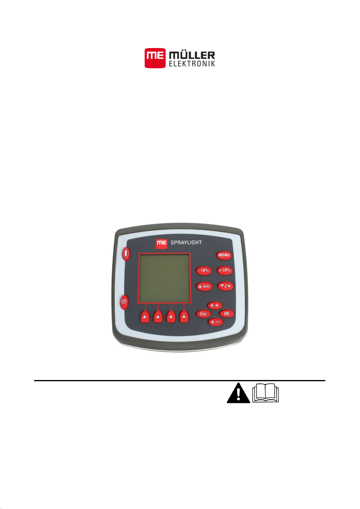
Installation and Operating Instructions
Spraylight
Version: V5.20150204
30283305-02-EN Read and follow these operating instructions.
Keep these operating instructions in a safe place for later
reference.
Page 2

Company details
Document
Copyright ©
Installation and Operating Instructions
Product: Spraylight
Document number: 30283305-02-EN
From software version: 2.00.13
Original language: German
Müller-Elektronik GmbH & Co.KG
Franz-Kleine-Straße 18
33154 Salzkotten
Germany
Phone: ++49 (0) 5258 / 9834 - 0
Fax: ++49 (0) 5258 / 9834 - 90
Email: [email protected]
Homepage: http://www.mueller-elektronik.de
Page 3
1
For your safety
6
1.1
Basic safety instructions
6
1.2
Layout and meaning of warnings
6
1.3
Intended use
7
1.4
User requirements
7
1.5
EC declaration of conformity
7
2
About these Operating Instructions
8
2.1
Target group of these Operating Instructions
8
2.2
Layout of operating instructions
8
3
Mounting and installation
9
3.1
System overview
9
3.2
Mounting the terminal
10
3.3
Connecting the cable
11
3.4
Connecting the battery connection cable
11
3.5
Installing the wheel sensor
11
3.5.1
Mounting the wheel sensor on the rim
12
3.6
Determining speed by means of the tractor's signal socket
15
3.7
Connecting section valves
16
3.8
Instructions on retrofitting
16
4
Product description
17
4.1
Performance description
17
4.2
Overview of keys
17
4.3
Screen structure
18
4.3.1
Work screen with a sprayer
18
4.3.3
Areas on the work screen
19
Spray data area
19
Tank display area
19
4.3.4
Structure of further screens
22
5
Basic control principles
23
5.1
Navigating in screens
23
5.1.2
Exit screen
23
5.1.3
Moving the cursor
23
5.2
Selecting and activating parameters
23
5.2.1
Inputting data
23
Contents
Contents
3.5.2 Mounting the wheel sensor on the drive shaft 14
4.3.2 Work screen for an orchard sprayer 18
Boom display area 20
Function icons section 21
5.1.1 Browsing between screens 23
5.2.2 Activating and deactivating functions 25
30283305-02-EN V5.20150204 3
Page 4
6
Preparing Spraylight for use
26
6.1
When should you configure what?
26
6.2
Configuring the basic settings of the on-board computer
27
6.2.2
Setting contrast and brightness
27
6.2.3
Selecting language
28
6.3
Entering sprayer parameters
28
6.3.1
Entering sprayer working width
28
6.3.3
Configuring the nozzle type
31
Selecting the type of nozzle
31
Calibrating non-ISO compliant nozzles
34
Recalibrating a nozzle when worn
34
6.3.4
Inputting tank size
36
6.4
Tank filling
37
6.4.2
Filling up the tank with TANK Control
38
6.5
Calibrating the flow meter
38
6.5.1
Calibrating the flow meter with the tank method
39
6.5.2
Calibrating the flow meter with the nozzle method
40
6.6
Calibrating the wheel sensor
41
6.6.1
Determining pulses per 100 meters
42
6.6.2
Manually entering the number of pulses for the wheel sensor
43
6.7
Set limit values for the spray pressure
43
6.8
Configuring Automatic mode
44
6.8.3
Setting the regulation value
45
6.9
Triggering hydraulic valves
45
6.10
Configuring the communication with an ISOBUS terminal
46
7
Applying the device in the field
47
7.1
Entering the set value
47
7.2
Controlling application
47
7.2.2
Using Manual mode
48
7.2.3
Starting application
48
7.2.4
Stopping application
49
7.3
Switching off sections
49
7.4
Selecting sections
49
7.5
Selecting sections when all sections are switched off
49
7.6
Working in localized mode
50
Contents
6.2.1 Setting date / time 27
6.3.2 Entering the number of nozzles per section 30
Calculating the output and amount applied by the nozzles on your machine 33
6.3.5 Setting a tank alarm 36
6.4.1 Filling up the tank without TANK Control 37
6.5.3 Manually entering the number of pulses per liter for the flow meter 41
6.8.1 Setting minimum working speed 44
6.8.2 Setting minimum automatic working speed 44
7.2.1 Using Automatic mode 47
7.6.1 Work screen in localized mode 50
4 30283305-02-EN V5.20150204
Page 5
7.6.2
Selecting and switching off sections in localized mode
50
7.6.4
Deactivating localized mode
51
7.7
Documenting work results
51
7.7.1
The Totals screen
51
7.7.2
The Daily counter screen
52
7.8
Working with hydraulic valves
53
7.8.1
Controlling hydraulic valves configured as keys
54
7.8.2
Controlling hydraulic valves configured as switches
54
8
Maintenance and servicing
55
8.1
Checking the software version
55
8.2
V24 interface
55
8.3
Activating simulated speed function
55
8.4
Displaying sensor status
56
8.5
Maintaining and cleaning device
57
8.6
Disposing of the unit
57
8.7
Technical specifications
57
8.8
Plug assignment - 8-pole flange socket
58
8.9
Plug assignment - 39-pole clip connector
58
9
Troubleshooting
60
9.1
Table of potential faults
60
Contents
7.6.3 Activating localized mode 50
7.7.3 Documenting work results with a daily counter 52
30283305-02-EN V5.20150204 5
Page 6
WARNING
physical injury, if not avoided.
CAUTION
physical injury or damage to property, if not avoided.
NOTICE
optimum work results.
1
1.1
1.2
For your safety
1
Basic safety instructions
For your safety
Please read the following safety instructions carefully before using the product for the first time.
▪ Never remove any safety mechanisms or stickers from the product.
▪ Read the operating instructions to the agricultural device which you want to control by using the
product.
▪ Before servicing or repairing the tractor, always disconnect the tractor from the Spraylight
terminal.
▪ Before charging the tractor battery, always disconnect the connection between the tractor and
the terminal Spraylight.
▪ Before performing any welding operations on the tractor or a trailed machine, always disconnect
the power supply to the Spraylight terminal.
▪ The product does not include any user serviceable parts. Do not open the casing.
▪ Do not make any unauthorized modifications to the product. Unauthorized modifications or use
may impair safety and reduce the service life or operability of the unit. Modifications are
considered unauthorized if they are not described in the product documentation.
Layout and meaning of warnings
All safety instructions found in these Operating Instructions are composed in accordance with the
following pattern:
Basic safety instructions
This signal word identifies medium-risk hazards, which could potentially cause death or serious
This signal word identifies low-risk hazards, which could potentially cause minor or moderate
This signal word identifies actions which could lead to operational malfunctions if performed
incorrectly.
These actions require that you operate in a precise and cautious manner in order to produce
There are some actions that need to be performed in several steps. If there is a risk involved in
carrying out any of these steps, a safety warning will appear in the instructions themselves.
Safety instructions always directly precede the step involving risk and can be identified by their bold
font type and a signal word.
Example
1. NOTICE! This is a notice. It warns that there is a risk involved in the next step.
2. Step involving risk.
6 30283305-02-EN V5.20150204
Page 7
1.3
1.4
1.5
For your safety
Intended use
1
Intended use
Spraylight is intended exclusively for use in agriculture as well as in wine-growing, fruit-cultivating,
and hop-growing operations. The manufacturer cannot be held responsible for any installation or use
of the system that deviates from or exceeds the scope of intended use.
The manufacturer cannot be held liable for any personal injury or property damage resulting from
such improper use. All risk involved during improper use lies with the user.
Intended use also includes the adherence to the conditions for operation and repairs prescribed by
the manufacturer.
All applicable accident prevention regulations and all other generally recognised safety, industrial,
and medical standards as well as all road traffic laws must be observed. Any unauthorized
modifications made to the equipment will void the manufacturer's warranty.
User requirements
▪ Learn how to operate the terminal correctly. The terminal must not be operated by anyone who
has not read the Operating Instructions.
▪ Please read and carefully observe all safety instructions and warnings contained in these
Operating Instructions and in the manuals of any connected vehicles and farm equipment.
EC declaration of conformity
This product has been manufactured in conformity with the following national and harmonised
standards as specified in the current EMC Directive 2004/108/EC:
▪ EN ISO 14982
30283305-02-EN V5.20150204 7
Page 8
Type of depiction
Meaning
2.
⇨
This will happen when you perform an action.
⇨
steps.
2
2.1
2.2
About these Operating Instructions
2
Target group of these Operating Instructions
About these Operating Instructions
Target group of these Operating Instructions
This operating manual is aimed at users of Spraylight.
Layout of operating instructions
The operating instructions explain step by step how you can perform certain operations with the
product.
We use the following symbols throughout these Operating Instructions to identify different operating
instructions:
1.
Actions that must be performed in succession.
Result of the action.
Result of an operating instruction.
This will happen when you have completed all
Requirements.
In the event that any requirements have been
specified, these must be met before an action
can be performed.
8 30283305-02-EN V5.20150204
Page 9
3
3.1
Mounting and installation
Mounting and installation
System overview
3
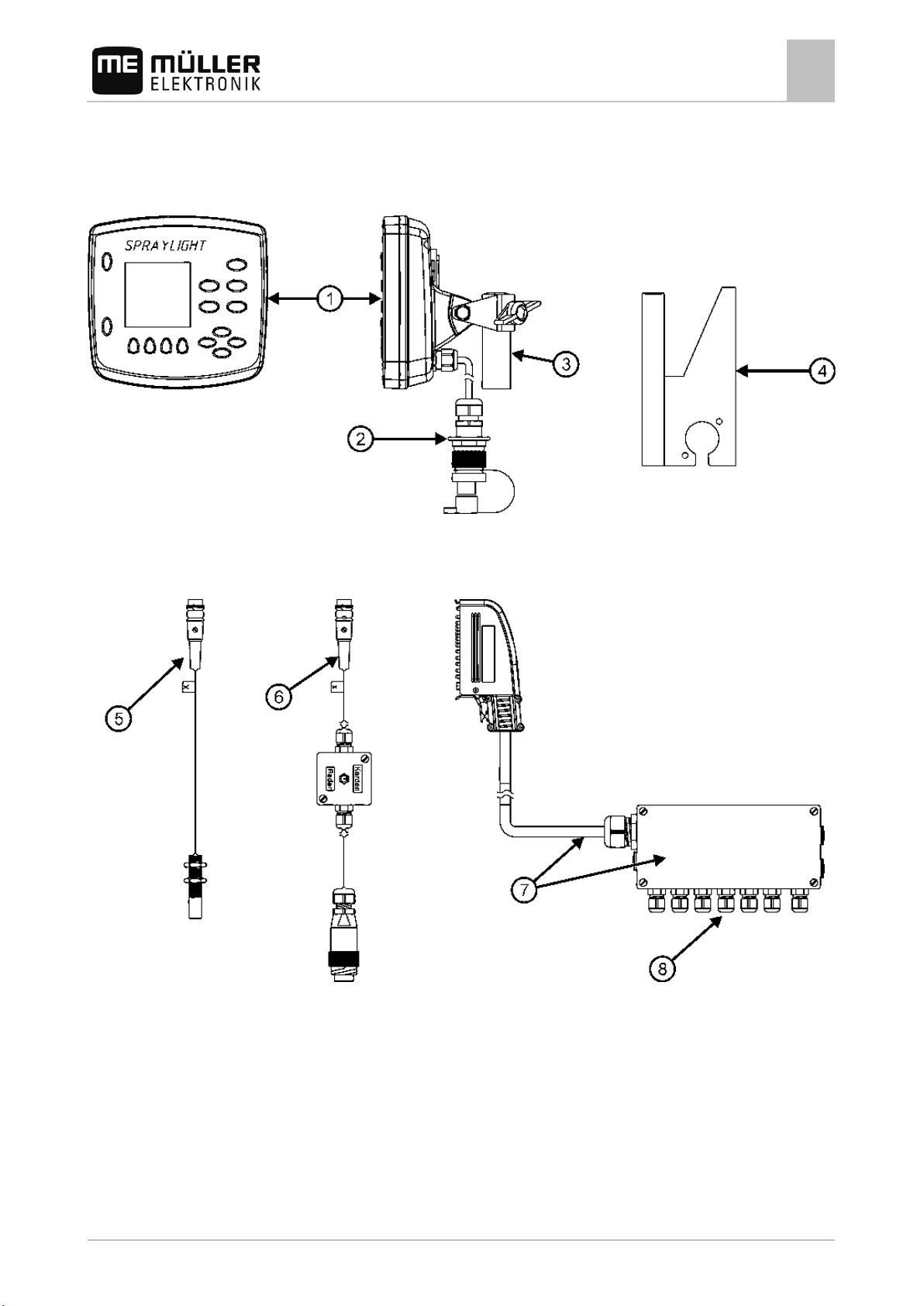
System overview
Spraylight - System overview
30283305-02-EN V5.20150204 9
Page 10
Item no.: 312084
Item no.: 312120
plug.
3.2
Procedure
Mounting and installation
3
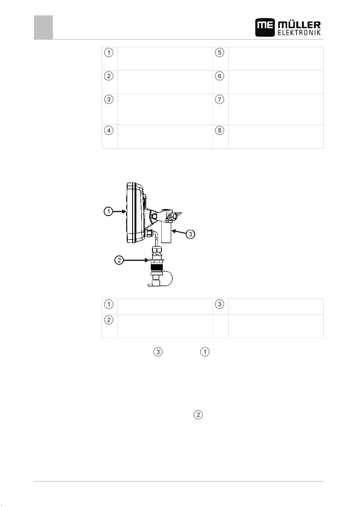
Mounting the terminal
Terminal / on-board computer
Included in scope of delivery
Wheel sensor (Sensor X)
Available for order
Voltage connection cable
Included in scope of delivery
Bracket for computer
Included in scope of delivery
Adapter cable for signal socket ISO11786
Available for order
Distributor with connector cable
Available for order
6.5m cable – Item no.: 30221071
10m cable - Item no.: 30221076
Mounting bracket
Available for order
Cable glands for connecting sections, bypass,
regulation, sensors
Item no.: 312075
Mounting the terminal
Mounting the terminal
Terminal / On-board computer
Voltage connection cable
Power connection cable with 3-pin connector
Bracket
for mounting the terminal
1. Screw the bracket to the computer .
2. Fasten the bracket with the terminal in the cab of the tractor.
NOTICE! The distance to the radio device or to the radio antenna must be at least one
metre.
A mounting bracket can be used to fasten the bracket in the cab.
3. Connect the terminal with the distributor.
4. Connect the power connection cable
to the battery connection cable.
10 30283305-02-EN V5.20150204
Page 11
connected to the distributor.
For connecting the distributor.
3.3
Procedure
3.4
3.5
Mounting and installation
Connecting the cable
3
Connecting the cable
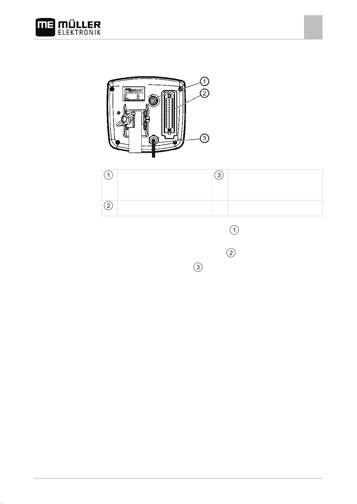
Connections
8-pole flange socket
For connecting the wheel sensor.
Only for use when the wheel sensor cannot be
Voltage connector cable
For connecting to the battery connector cable.
39-pole clip connector
1. Connect the wheel sensor to the 8-pole flange socket .
Only for use when the wheel sensor cannot be connected to the distributor.
2. Connect the distributor to the 39-pole clip connector
3. Connect the voltage connector cable
with the battery connector cable.
.
Connecting the battery connection cable
When connecting the battery connection cable, read the instructions supplied with this cable.
Installing the wheel sensor
A wheel sensor (also called Sensor X) is a sensor that determines the speed of the vehicle and
transmits it to the Spraylight.
The wheel sensor consists of a sensor and multiple magnets.
The magnets are mounted at regular intervals onto the rim or drive shaft of the tractor. The wheel
sensor is mounted onto the king-pin bearing. When the rim or drive shaft rotate, the magnets rotate
with them.
30283305-02-EN V5.20150204 11
The sensor sends a pulse to a job computer or an on-board computer every time that a magnet
passes in front of it.
The software calculates the current speed on the basis of the number of pulses within a defined
period.
You can mount the wheel sensor in the following positions:
▪ On the rim of the towed machine
▪ On the front wheel of the tractor
▪ On the drive shaft of a tractor with all-wheel drive
Page 12
Must be at least 25 mm.
(optional)
Mount in an anti-magnetic manner.
3.5.1
Mounting and installation
3
Installing the wheel sensor
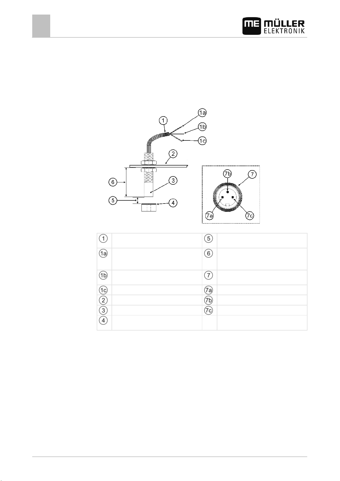
Mounting the wheel sensor on the rim
The wheel sensor should be mounted on the rim in the following instances:
▪ For a trailer-sprayer – on the rim of the trailer-sprayer.
▪ For a mounted sprayer and tractor with no all-wheel drive – on the front wheel of the tractor.
Mounting the wheel sensor on the rim
Cable to 3-pole plug
White color: Ground
Brown color: +12 Volt
Green color: Wheel
Mounting angle
Wheel sensor with a blue cap
Magnet with a red cap
Switching distance
Must be 5 to 10 mm.
Distance from the angle bracket to the end
of the sensor
3-pole plug – Pin assignment
White color: Ground
Brown color: +12 Volt
Green color: Wheel
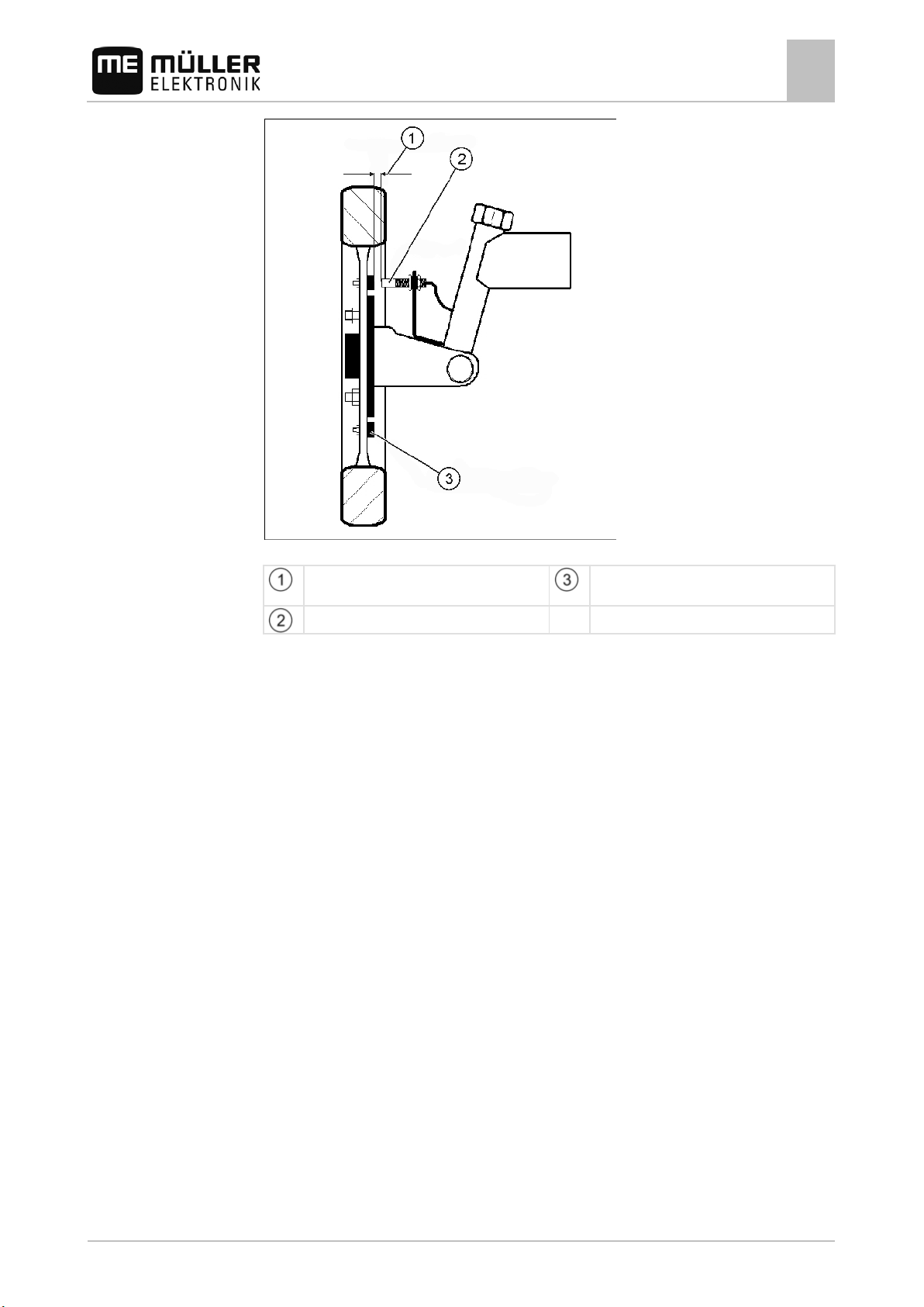
The following illustration shows the position of the wheel sensor and the magnet on the rim:
12 30283305-02-EN V5.20150204
Page 13
5-10 mm
Procedure
Mounting and installation
Installing the wheel sensor
3
Position of the wheel sensor and magnet on the rim
Switching distance
Wheel sensor
Magnet
1. Calculate the number of magnets required.
The number of magnets is dependent on the size of the wheel.
The distance traveled from pulse to pulse must not exceed 60 cm.
Calculation:
Wheel circumference ÷ 60 cm = number of magnets
e. g.:
256 cm ÷ 60 cm = 4.27 = min. 5 magnets
2. Mount the magnets on the wheel shell with the V4A screws provided.
The magnets must be distributed equally around the circumference of the rim.
3. Mount the wheel sensor onto the king-pin bearing using the bracket provided. The end of the
sensor must point to the magnets.
The distance between the sensor and the magnets must be between 5 -10 mm.
The following illustration shows the position of the sensor and the magnets:
4. Connect the wheel sensor electronically:
You can do this in the following ways:
- If you mounted the wheel sensor on the trailer-sprayer, connect the wheel sensor to the
distributor. Use the 39-pole plug.
- If you mounted the wheel sensor on the tractor wheel, connect the wheel sensor directly to the
Spraylight. Plug the sensor's 3-pole plug into the 8-pole flange socket of the Spraylight.
30283305-02-EN V5.20150204 13
Page 14
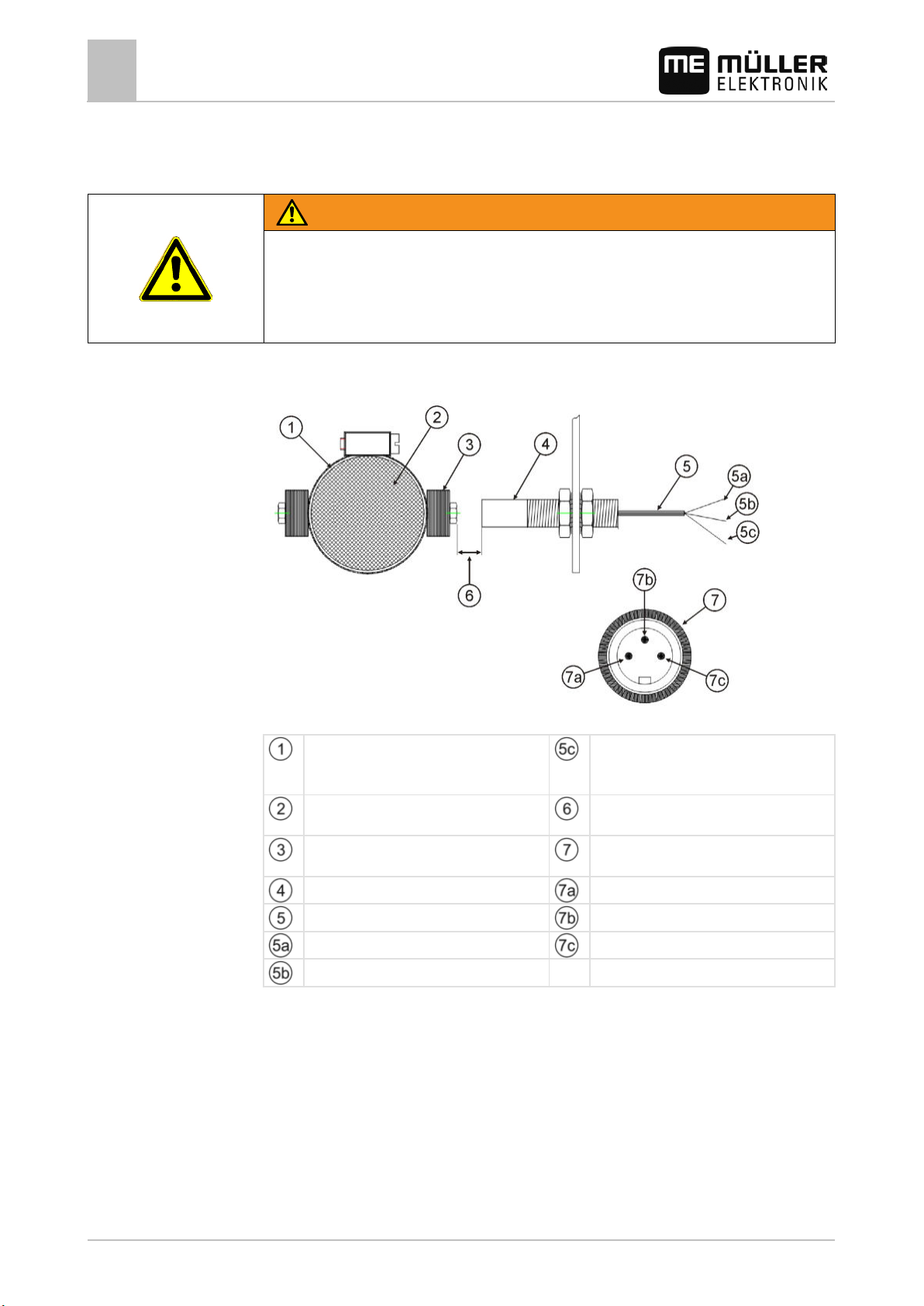
WARNING
on the design.
5 to 10 mm
Mount in an anti-magnetic manner.
(plug is optional)
3.5.2
Procedure
Mounting and installation
3
Installing the wheel sensor
Mounting the wheel sensor on the drive shaft
Rotating machine parts
Risk of drawing-in and crushing injuries
◦ Switch off the motor before mounting the wheel sensor!
◦ Ensure that no one starts the motor while you are mounting the wheel sensor!
The wheel sensor should be mounted on the drive shaft in the following instances:
▪ On a mounted sprayer and tractor with all-wheel drive.
Mounting the wheel sensor on the drive shaft
Hose clamp with magnets
There can be one or two magnets, depending
Drive shaft
Magnet with a red cap
Wheel sensor with a blue cap
Cable to 3-pole plug
White color: Ground
Brown color: +12 Volt
Green color: Wheel
Switching distance
3-pole pin – pin assignment
White color: Ground
Brown color: +12 Volt
Green color: Wheel
1. Mount the hose clamp with magnet on the drive shaft.
2. Mount the sensor such that it is vibration-free.
3. The sensor must point towards the magnets at a distance of 5 - 10 mm.
The following illustration shows the position of the sensor and the hose clamp:
14 30283305-02-EN V5.20150204
Page 15
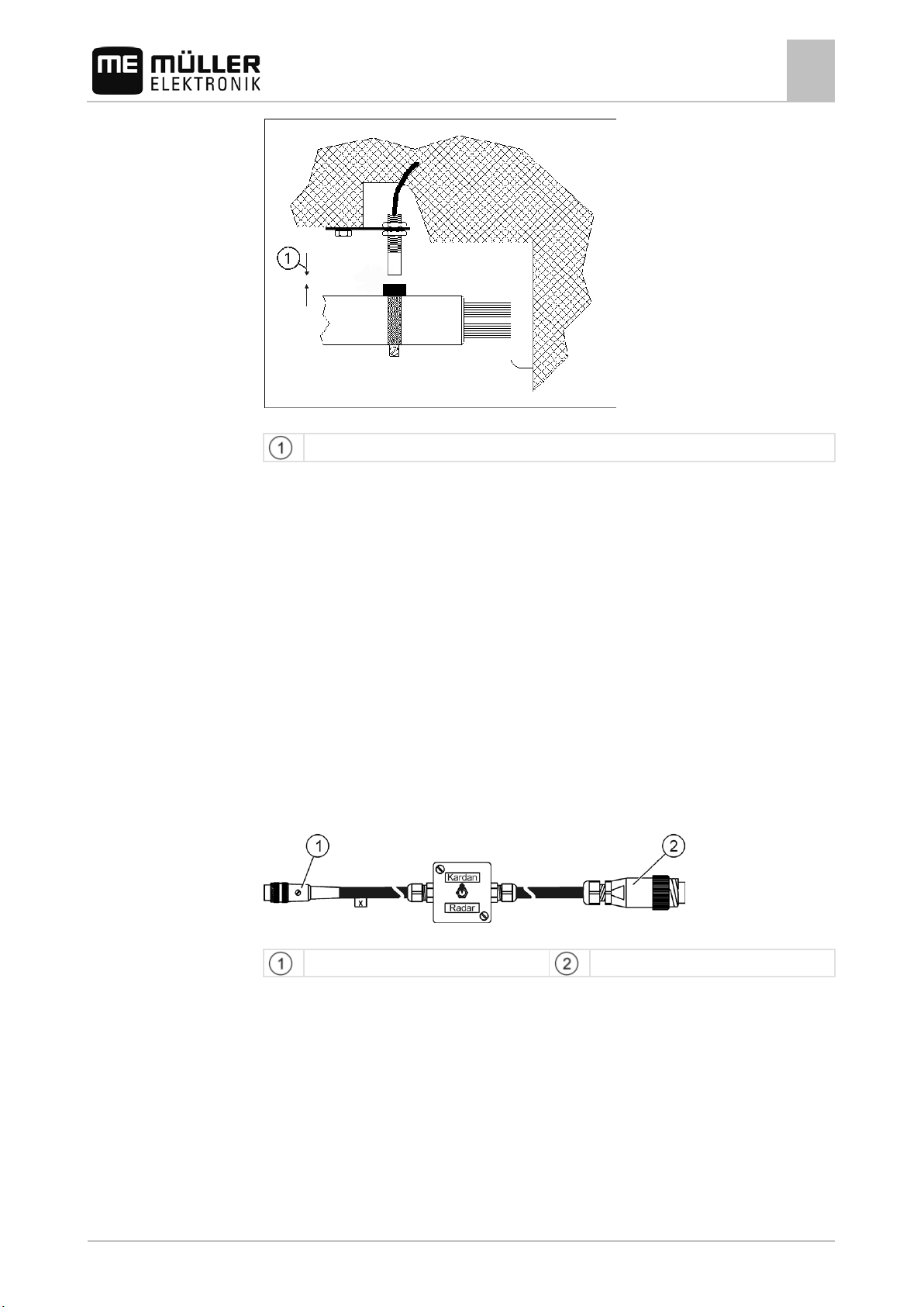
3.6
Mounting and installation
Determining speed by means of the tractor's signal socket
3
Position of the wheel sensor on the drive shaft
The distance between the sensor and the magnets must be between 5 and10 mm.
Determining speed by means of the tractor's signal socket
If your tractor is fitted with a signal socket and you have no wheel sensor, you can transmit the speed
of the tractor by means of the signal socket to the Spraylight.
if you determine the speed by means of the tractor's signal socket, you will still need to determine the
pulses per 100 m.
You may require an adapter cable to connect the Spraylight to the signal socket. This adapter cable
can be ordered from Müller-Elektronik using Item no. 312120. The adapter cable can be connected to
tractors from the following manufacturers:
▪ Fendt
▪ John Deere
▪ Deutz
▪ CLAAS
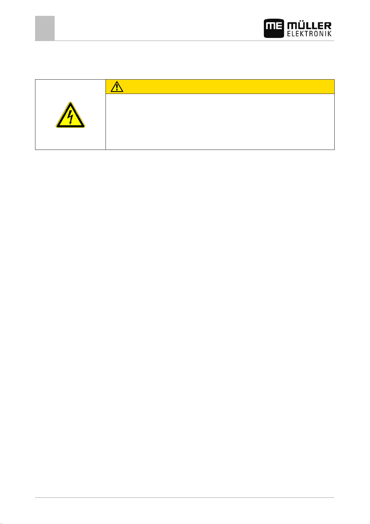
The following illustration is a diagrammatic representation of the cable:
Cable for connection to the signal socket [312120]
Cable to the computer, 3-pole
Cable to the signal socket, 7-pole
30283305-02-EN V5.20150204 15
Page 16
CAUTION
section.
3.7
3.8
Selecting components
Mounting and installation
3
Connecting section valves
Connecting section valves
Damage to the implement caused by solenoid valves
If you use solenoid valves as section valves, the device will be damaged by over-current.
User responsibility
◦ Connect the system only to motorized valves.
◦ Pay attention to the maximum power consumption mentioned in the "Technical data [➙ 57]
"
Instructions on retrofitting
Instructions on how to retrofit electrical and electronic farm equipment and/or
components
Agricultural equipment used today features electronic components and parts whose function can be
affected by other farm equipment which emits electromagnetic waves. Such effects could lead to
personnel being put in danger, if the following safety instructions are not adhered to.
When selecting components, make sure first of all that the retrofitted electrical and electronic
components comply with the current version of the EMC Directive 2004/108/EC and carry the CE
marking.
When retrofitting a machine with electrical and electronic farm equipment and/or components
connected to the vehicle's electrical system, it is your own responsibility to check whether the
installation causes interference with the vehicle's electronic system or other components. This
applies, in particular, to the electronic control of:
▪ electronic hitch control (EHR),
▪ front linkage,
▪ power take off (PTO),
▪ engine,
▪ gear.
Additional requirements
16 30283305-02-EN V5.20150204
The following requirements must be met in order to retrofit mobile communication systems (e.g. radio,
phone):
▪ All farm equipment must be approved and installed in accordance with the regulations applicable
in the respective country.
▪ The equipment must be installed as a fixed installation.
▪ The operation of portable or mobile farm equipment in the interior of the vehicle is only permitted
via a connection to a permanently installed exterior antenna.
▪ The transmitting part must be spatially separated from the vehicle's electronic system.
▪ When attaching the antenna, pay attention to proper installation, including a sound ground
connection between the antenna and the vehicle's ground wire.
For information on wiring and installation as well as the maximum allowable current consumption,
please also refer to the installation guide provided by the machine manufacturer.
Page 17
Access menu function icons
In Manual mode: Reduce pressure
4
4.1
4.2
Controls
Product description
Product description
Performance description
4
Performance description
Spraylight features the following functions:
▪ Up to seven section switches with main section switch
▪ Manual and automatic control of the application rate
▪ Up to four hydraulic functions
▪ Display of current speed
▪ Display of current application rate
▪ Display of remaining workable area
▪ Display of the current tank content
▪ Documentation of work results
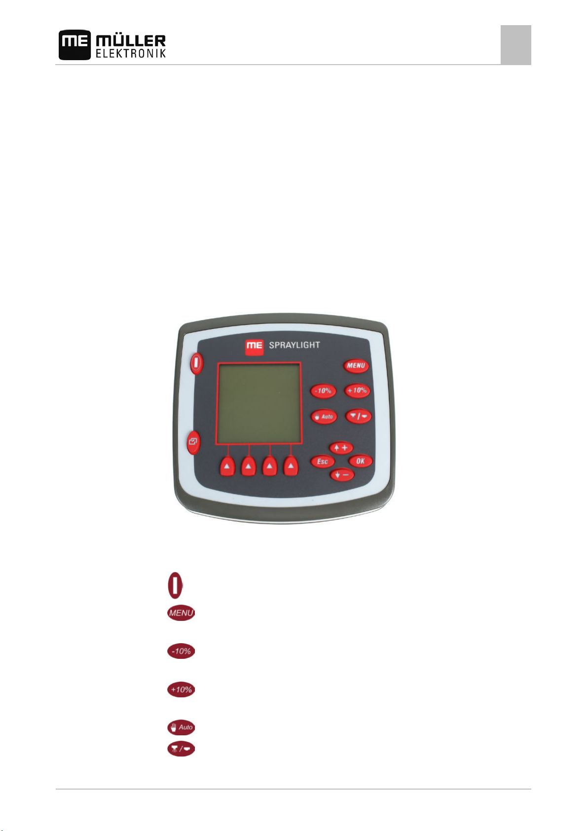
Overview of keys
Front view of Spraylight
Buttons – Buttons always having the same function. Named 'buttons' from now.
Switching on and off
Return to the work screen
In Automatic mode: Reduce the set value by 10%
In Automatic mode: Increase the set value by 10%
In Manual mode: Increase pressure
30283305-02-EN V5.20150204 17
Switch between manual and automatic mode
Switch section main switch on and off
Page 18
Bring up work screen
4.3
4.3.1
4.3.2
Product description
4
Screen structure
Switch between groups of function icons on the work screen
In the menus – move the cursor up one line
Increase the value by one during data input
In the menus – move the cursor down one line
Reduce the value by one during data input
Exit screen
Cancel data input
Close a pop-up window
Confirm data input
Function buttons – Buttons, the function and meaning of which depends upon the symbols (function
symbols) displayed on the screen. Function buttons may have different functions in different screens.
Named 'function buttons' from now.
Activate the functions represented by the function icons
Screen structure
Work screen with a sprayer
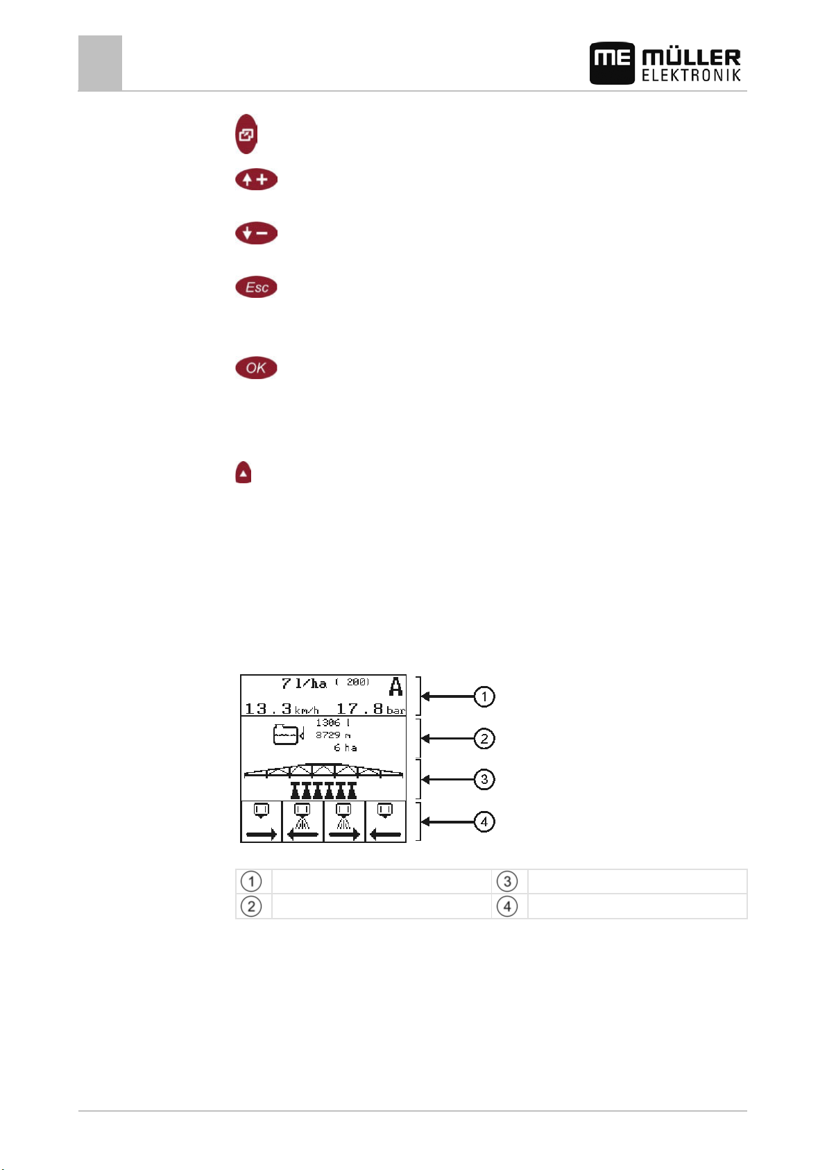
The work screen is always displayed during work and contains the most important information. The
work screen informs you about the status of the connected machine during work.
The work screen is divided into four areas.
Work screen areas - sprayer
Spray data area
Tank display area
Boom display area
Function icons section
18 30283305-02-EN V5.20150204
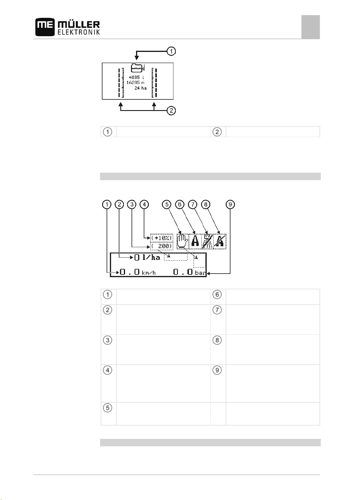
Work screen for an orchard sprayer
The only difference between the orchard sprayer work screen and the sprayer work screen are the
boom display and tank display areas.
Page 19
Current sprayer speed in km/h.
Automatic mode is switched on.
working speed has been undercut.
and higher than the Min.Speed.
the adjustment.
pressure must be adjusted manually.
4.3.3
Product description
Screen structure
4
Work screen for an orchard sprayer
Tank display area
Boom display area
Areas on the work screen
Spray data area
The following information is shown in the Spray data area:
Spray data area
Speed
Current value
Current application rate in l/ha.
Set value
Preset application rate in l/ha.
Automatic mode
Sprayer off icon
If this icon appears on the display, then a set
value of 0 l/ha has been input, or the minimum
Automatic mode off icon
When this icon appears on the display, the
current speed is lower than the Auto.speed
30283305-02-EN V5.20150204 19
Percentage adjustment of the set value
The set value can be adjusted in Automatic
mode in 10% increments. The percentage
Spray pressure
Current pressure of the sprayed liquid in bar
(only when the pressure sensor is configured).
figure is displayed approx. 2 seconds following
Manual mode
Manual mode is switched on. The spray
Tank display area
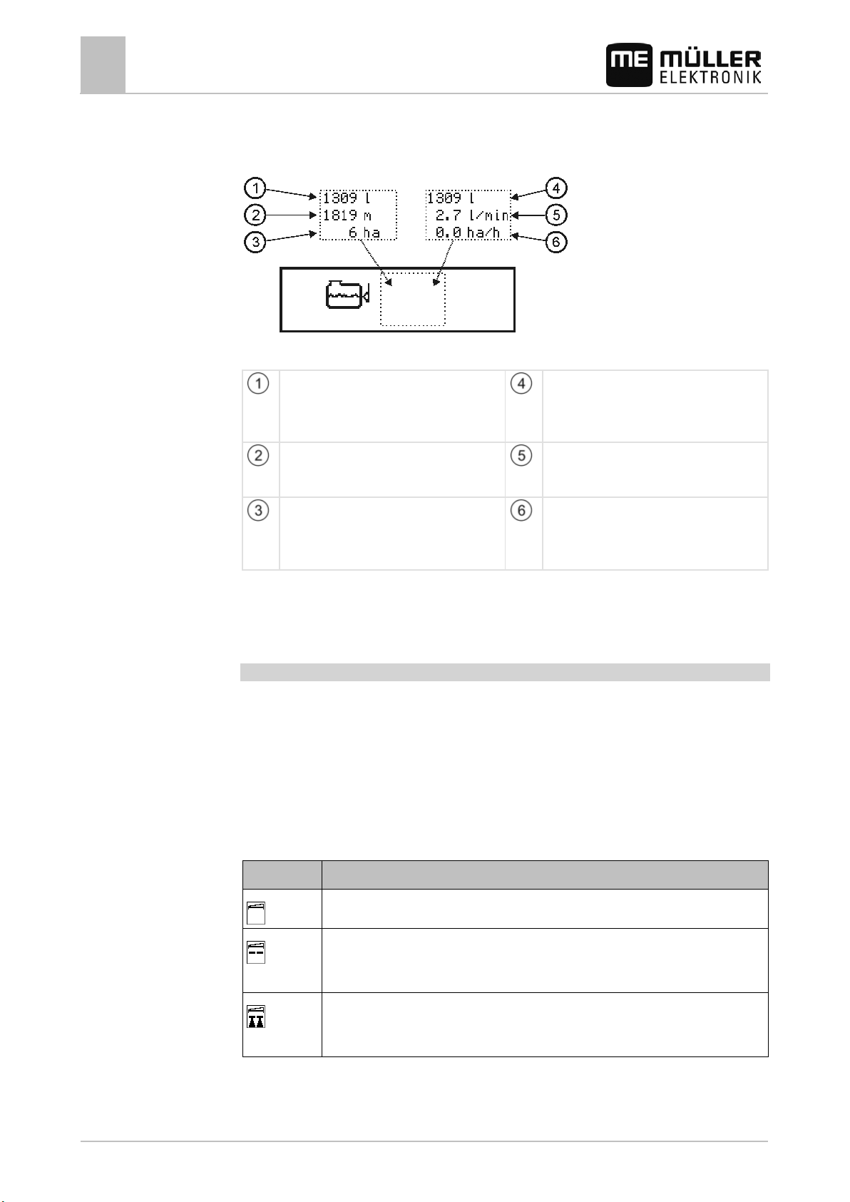
The Tank display area provides information which will help you assess the status of the tank.
Page 20
content.
content.
current conditions.
Section is ready for application.
Section is applying.
Possible states
Example
Product description
4
Screen structure
The type of information shown changes every three seconds.
The following illustration shows the meaning of the information displayed.
Tank display area
Current tank content
Depending on the spray equipment, this will
show either the calculated or measured tank
Current tank content
Depending on the spray equipment, this will
show either the calculated or measured tank
Workable distance
This distance can still be processed under the
Workable area
The area shown here can still be processed
Flow rate per minute
Flow rate through the main flow meter.
Area output / hour
with the current tank content and the current
application rate.
Hydraulic valve icons may also appear in the Tank display area.
Read more about this in Chapter Working with hydraulic valves [➙ 53].
Boom display area
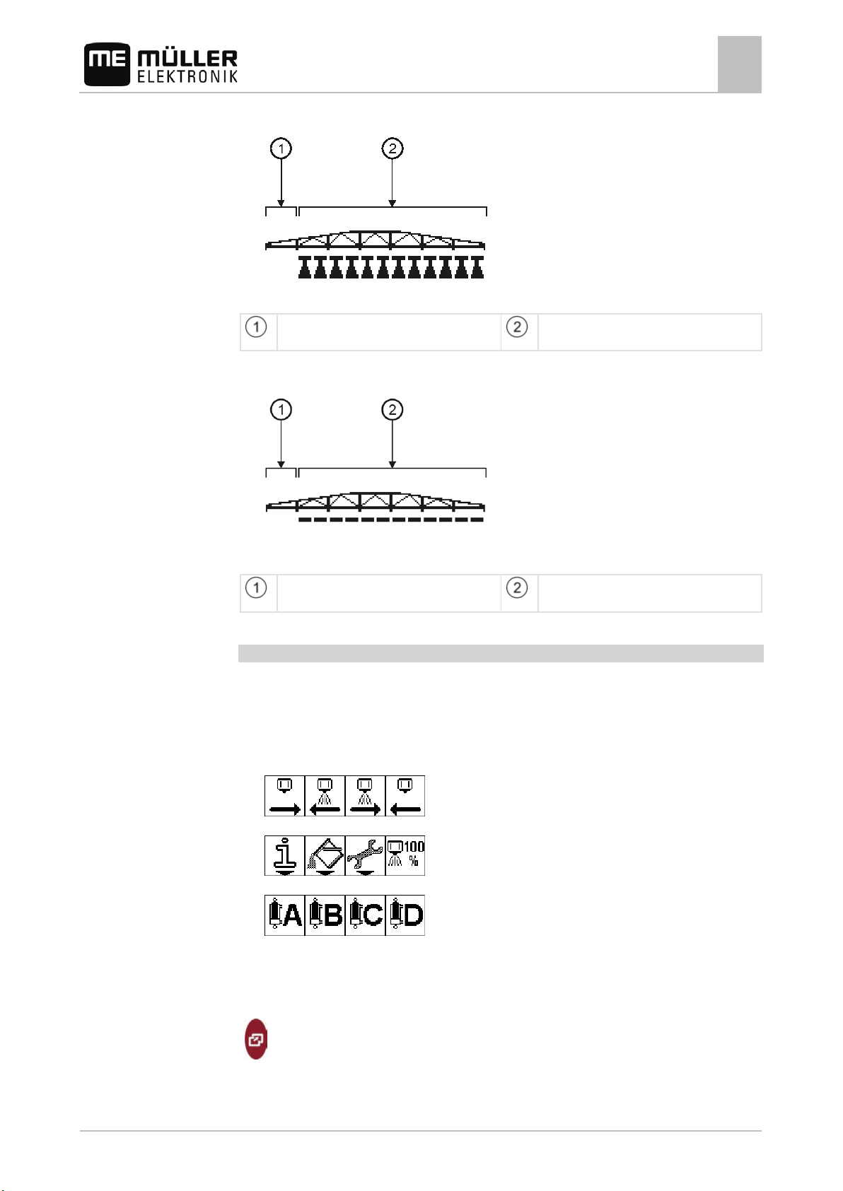
In the boom display you find the following information:
▪ Number of sections
▪ Which sections have been selected or switched off
▪ Which sections are applying
The sections can be in three states.
You can read a section's state in the work screen in the boom terminal area.
The following section status settings are possible:
Display Section status
20 30283305-02-EN V5.20150204
Section is switched off.
Section is selected.
Section is selected and the main section switch is switched on.
Page 21
is switched off.
are selected and applying.
is switched off.
are selected but are not yet applying.
Product description
Screen structure
4
Boom display area – example 1
Section 1
Sections 2 to 7
Boom display area – example 2
Section 1
Sections 2 to 7
Function icons section
The lower area of the work screen shows the function symbols. The lower area of the work screen
shows the function symbols. With Spraylight, four function symbols can be shown simultaneously
here.
There are three groups of function icons on the work screen:
▪ Function icons for operating the sections
▪ Function icons for menus
▪ Function icons for hydraulics (optional)
The number of hydraulic function icons displayed depends on the number of hydraulic valves
that you have configured.
Controls
30283305-02-EN V5.20150204 21
Switching between groups of function icons
Page 22
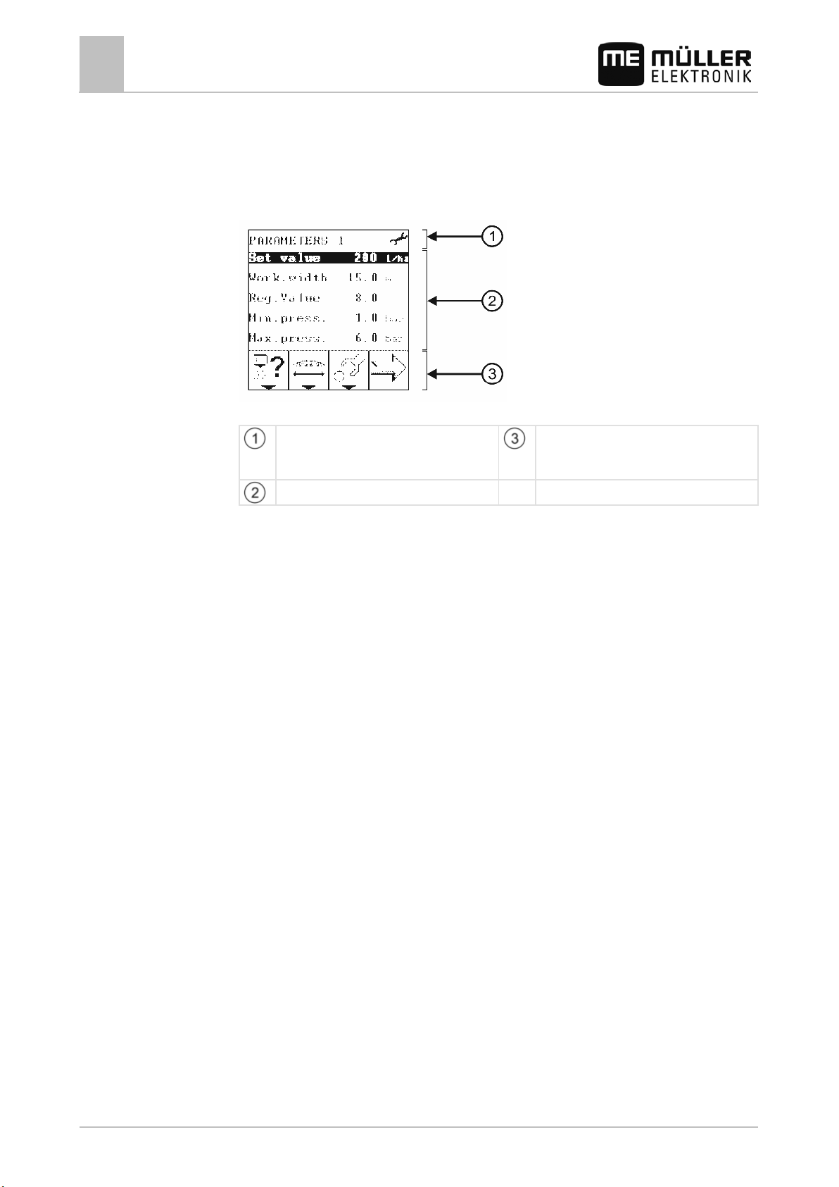
screen
4.3.4
Product description
4
Screen structure
Structure of further screens
In addition to the work screen, further screens are displayed with Spraylight.
These screens always consist of the following three areas:
Screen structure
Header area
contains the designation of the displayed
Function symbol area
Icons that can be pressed on this screen.
Screen content
22 30283305-02-EN V5.20150204
Page 23
5
5.1
5.1.1
Controls
5.1.2
Controls
Controls
5.2
5.2.1
Basic control principles
Basic control principles
Navigating in screens
5
Navigating in screens
Browsing between screens
There are screens that have too many entries to display them all on one screen. In these screens you
may need to browse further.
The following function icons tell you that you can browse further in a screen. You can press the
associated function button to browse further.
Browse to the next screen
Exit screen
Exiting the data input screen will cancel the data input.
You can exit a screen in the following ways:
Exit screen
To switch to the work screen (does not work on data input screens)
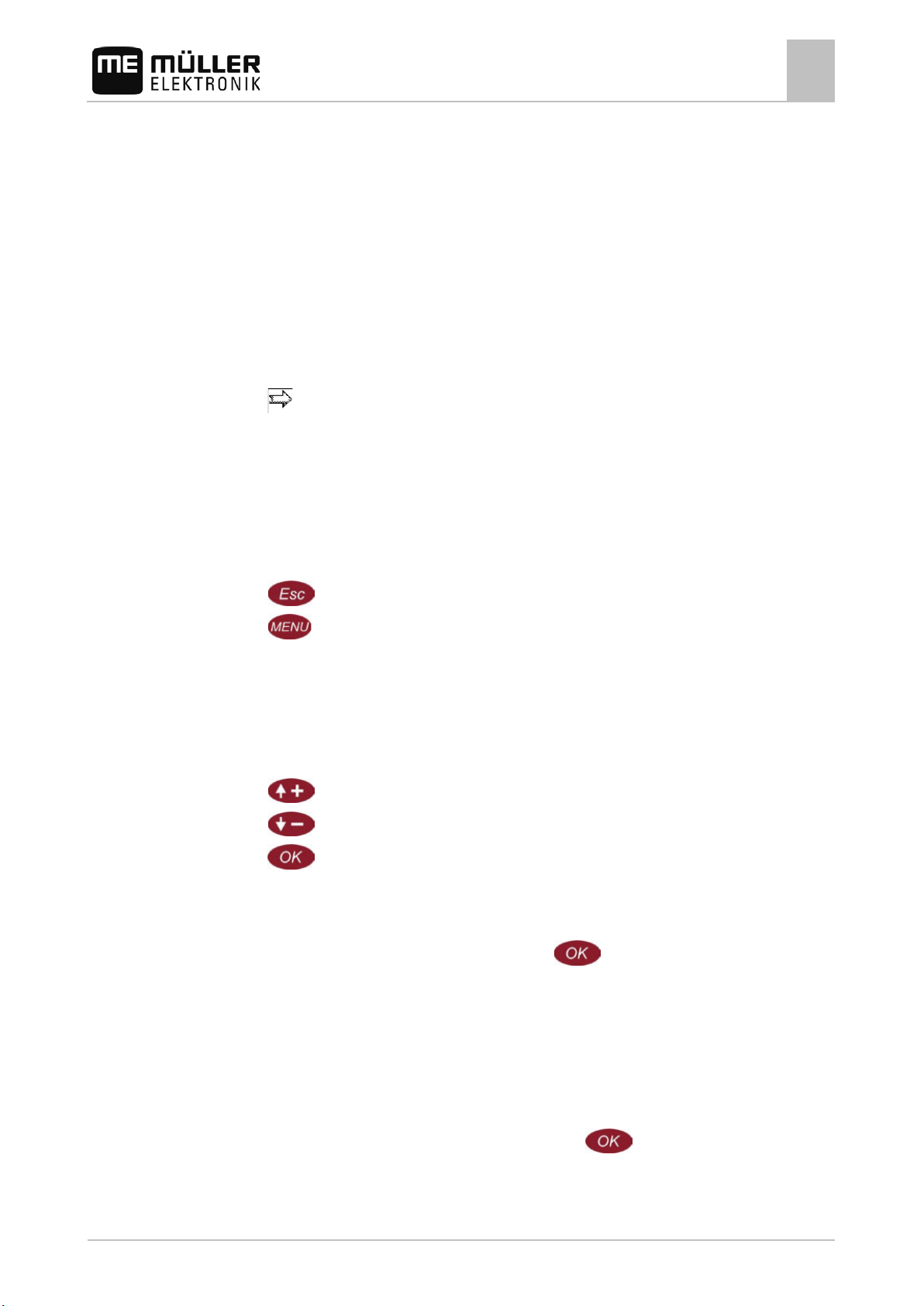
5.1.3
Moving the cursor
On many screens, you can select individual lines to change their value.
Move the cursor up one line
Move the cursor down one line
Confirm your choice
Selecting and activating parameters
Marking a parameter with your cursor and pressing
depending on the parameters:
▪ Input data
▪ Activate or deactivate function.
Inputting data
Data is always input in the same way, and you can do this on the Data input screen.
gives you the following options
The data input screen always appears when you use the
key to activate a parameter for
which you can input data.
30283305-02-EN V5.20150204 23
Page 24
Marks the number which can be modified.
Controls
Basic control principles
5
Selecting and activating parameters
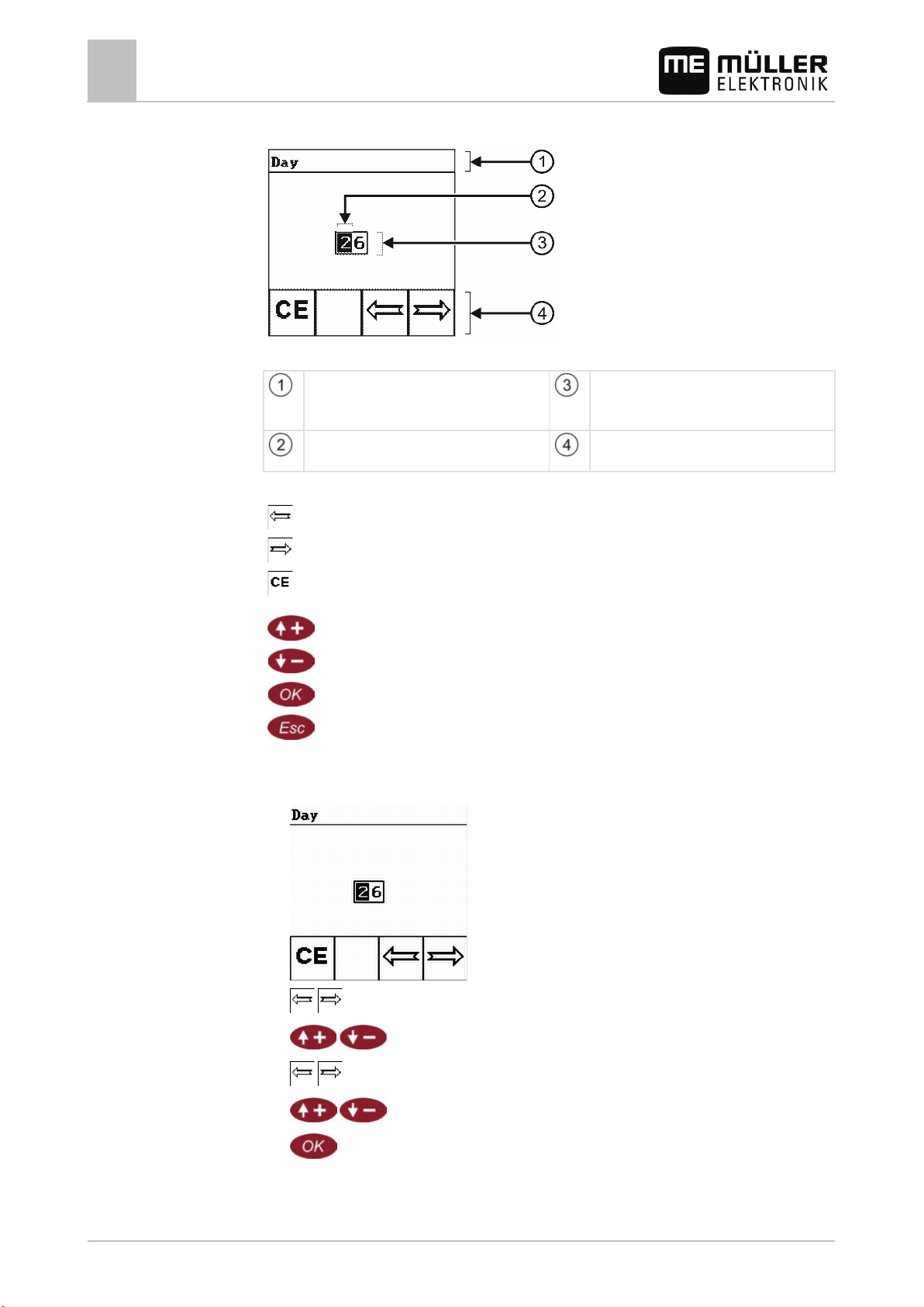
Data input screen
Data input screen
Header area
Contains the name of the parameter whose
value is being input.
Cursor
Input field
Contains number fields for entering the value.
Function icons
Procedure
Move cursor to the left
Move cursor to the right
Set all numbers to 0
Increase marked number by one
Decrease marked number by one
Confirm data input and finish
Cancel data input
1. Make sure that you have called up the data input screen!
2. The data input screen appears:
24 30283305-02-EN V5.20150204
3.
- Move the cursor to the desired point.
4.
5.
6.
7.
- Set the desired number.
- Move the cursor to the desired point.
- Set the desired number.
- Confirm and finish input.
⇨ The new value is accepted by the Spraylight.
Page 25
5.2.2
Procedure
Basic control principles
Selecting and activating parameters
5
Activating and deactivating functions
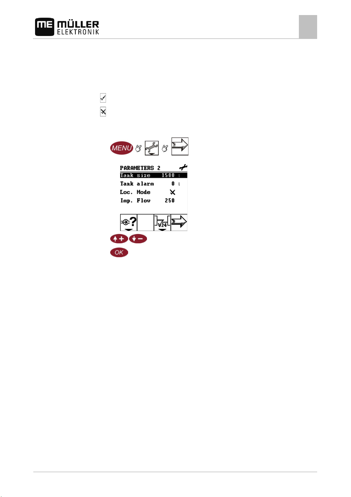
You can activate and deactivate certain functions on the Spraylight.
You can recognize these functions with the following icons:
- Function is activated
- Function is deactivated
1. Switch to the Parameter No. screen:
For example:
⇨ The following screen appears:
2.
3.
- Highlight the line with the name of the function.
- Activate or deactivate function.
⇨ The icon beside the parameter changes.
30283305-02-EN V5.20150204 25
Page 26
Function
Initial start-up
Start of season
In other instances
Language ●
weeks without power.
of nozzles in a section
Tank alarm ●
meter
pressure is incorrect
Min.press. ●
Max.press. ●
Auto.speed ●
6
6.1
configure what?
Preparing Spraylight for use
6
When should you configure what?
Preparing Spraylight for use
After you have connected all components of the system, you must configure Spraylight and the
connected components.
To configure the system, you must carry out the following:
▪ Enter the machine parameters
▪ Calibrate the sensors
▪ Set limit values for spray pressure (Min. pressure and Max. pressure)
▪ Configure Automatic mode
When should you
Read the chapter below to find out more about this.
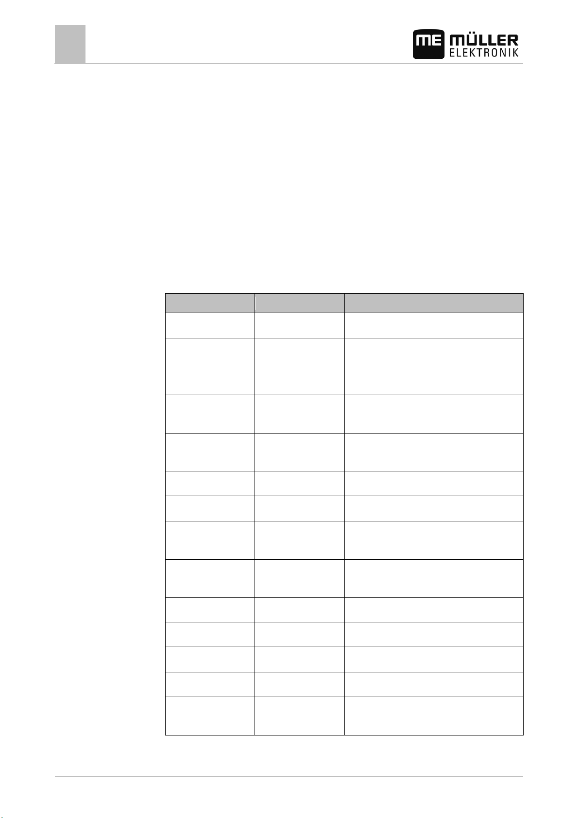
When should you configure what?
The following table shows an overview of the configurable functions and when these functions must
be configured:
Date / time ● Changing the clocks.
After more than two
Working width ● Changing the working
width
Nozzles per section ● Changing the number
Tank size ● Changing the tank size
26 30283305-02-EN V5.20150204
Calibrating the flow
Calibrating the wheel
sensor
● ● Displayed spray
● ● Displayed speed differs
from actual speed.
Min. Speed ●
Reg.Value ● The controls are too
slow or too sensitive.
Page 27
6.2
6.2.1
When to enter?
Procedure
6.2.2
Procedure
Preparing Spraylight for use
Configuring the basic settings of the on-board computer
6
Configuring the basic settings of the on-board computer
To configure the basic settings, you must carry out the following:
▪ Select the language
▪ Set contrast and brightness
▪ Set date / time
The following sections contain detailed instructions.
Setting date / time
▪ Prior to initial startup.
▪ When Spraylight has had no power supply for more than two weeks.
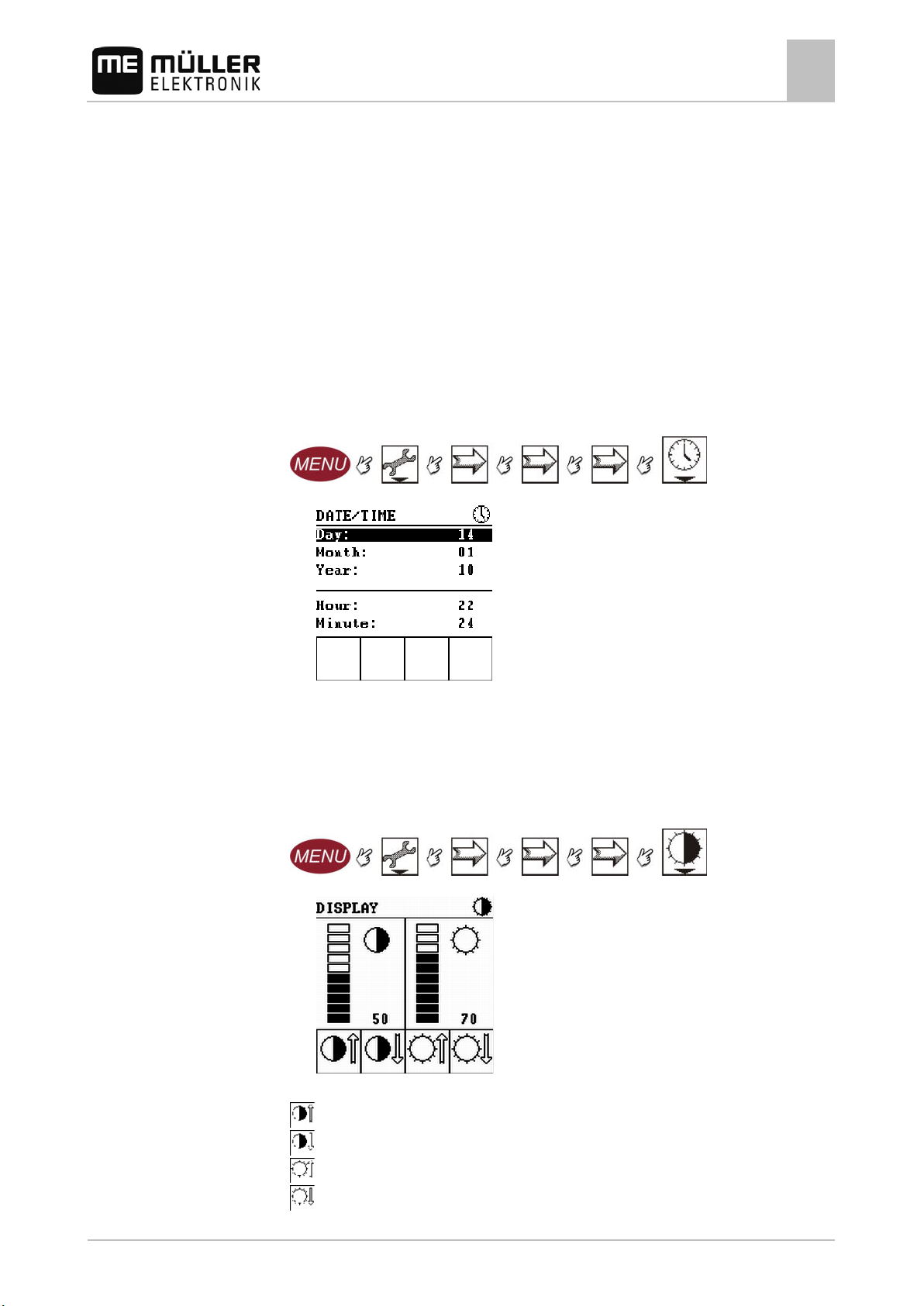
1. Switch to the Date/time screen:
⇨ The following screen will appear:
2. Modify the required parameters.
⇨ The new date and time appear on the screen Parameter 4
Setting contrast and brightness
1. Change to Display screen:
⇨ The following screen will appear:
2. Configure the screen via the following function buttons:
- Increase contrast
- Reduce contrast
- Increase brightness
- Reduce brightness
30283305-02-EN V5.20150204 27
Page 28
6.2.3
Procedure
6.3
6.3.1
When to enter?
Preparing Spraylight for use
6
Entering sprayer parameters
3. - Exit screen.
⇨ The modifications are adopted.
⇨ You have adjusted contrast and brightness of the screen.
Selecting language
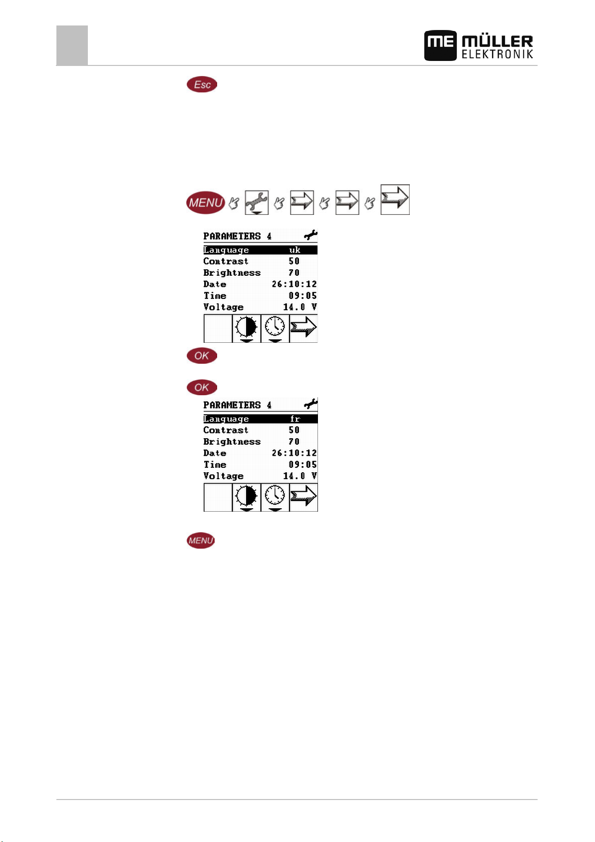
1. Switch to the Parameters 4 screen:
⇨ The following screen appears:
2.
- Select a language.
A new language abbreviation is shown in the Language line every time that you press the
key.
⇨
Continue to press the key until the abbreviation for the desired language appears.
3.
- Confirm.
⇨ The terminal restarts.
⇨ The language of the terminal then changes.
Entering sprayer parameters
Procedure
28 30283305-02-EN V5.20150204
if you have connected the Spraylight to the sprayer, you must input the sprayer parameters.
Entering sprayer working width
▪ Prior to initial startup.
▪ When there is a change to the sprayer's working width.
Saving working widths
You can save multiple working widths in Spraylight and then select the required one.
To save multiple working widths:
Page 29
Procedure
Preparing Spraylight for use
Entering sprayer parameters
6
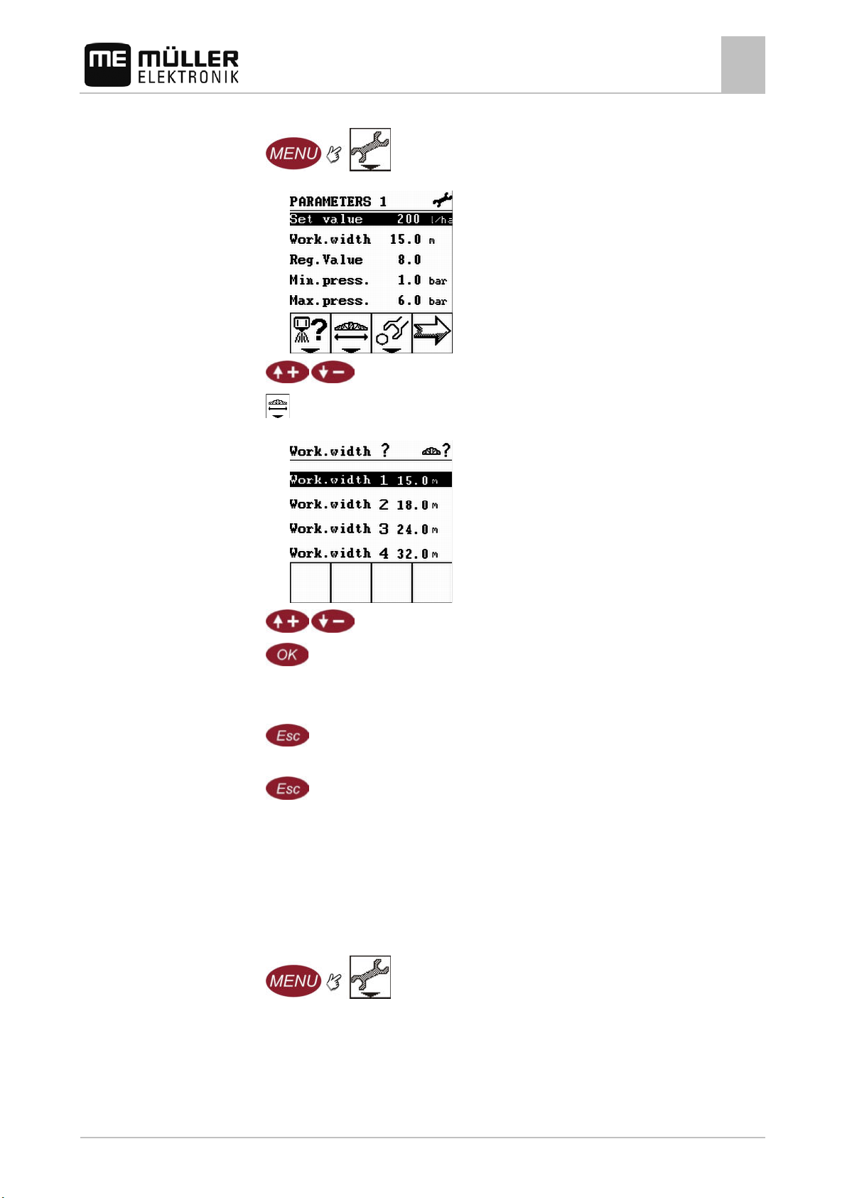
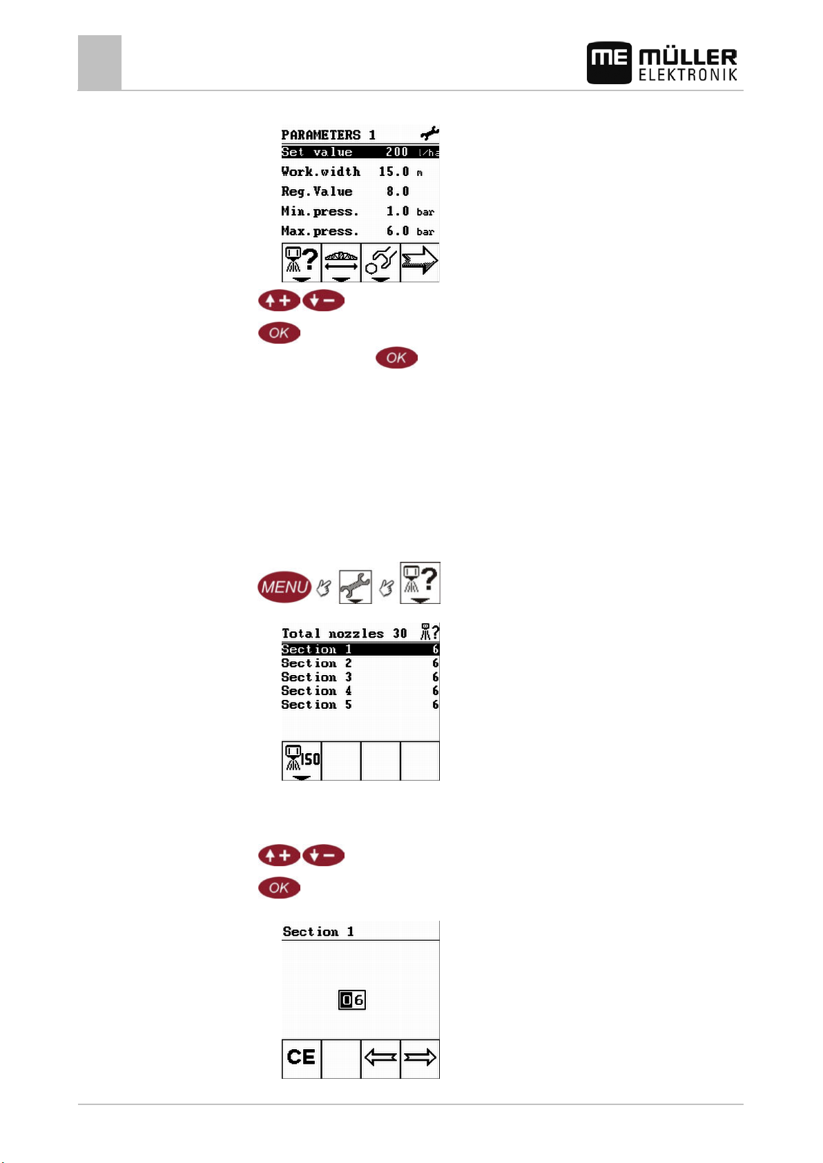
1. Switch to the Parameters 1 screen:
⇨ The following screen appears:
2.
3.
- Highlight the Work.width line.
- Press
⇨ The Work.width ? screen appears:
4.
5.
Mark one of the four positions.
- Confirm.
⇨ The data input screen appears.
6. Input a working width.
7.
- Exit the screen.
⇨ The Work.width ? screen appears.
8.
- Exit the screen.
⇨ The Parameters 1 screen appears.
⇨ You have saved a working width.
Selecting a working width
To select a saved working width:
1. Switch to the Parameters 1 screen:
30283305-02-EN V5.20150204 29
Page 30
6.3.2
Procedure
Preparing Spraylight for use
6
Entering sprayer parameters
⇨ The following screen appears:
When to enter?
2.
3.
- Highlight the Work.width line.
- Press to select another working width.
⇨ Every press of the
key displays a different working width beside the parameter
Work.width.
⇨ You have selected a working width.
Entering the number of nozzles per section
You must enter the number of nozzles installed on each section.
▪ Prior to initial startup.
▪ When the number of nozzles in a section changes.
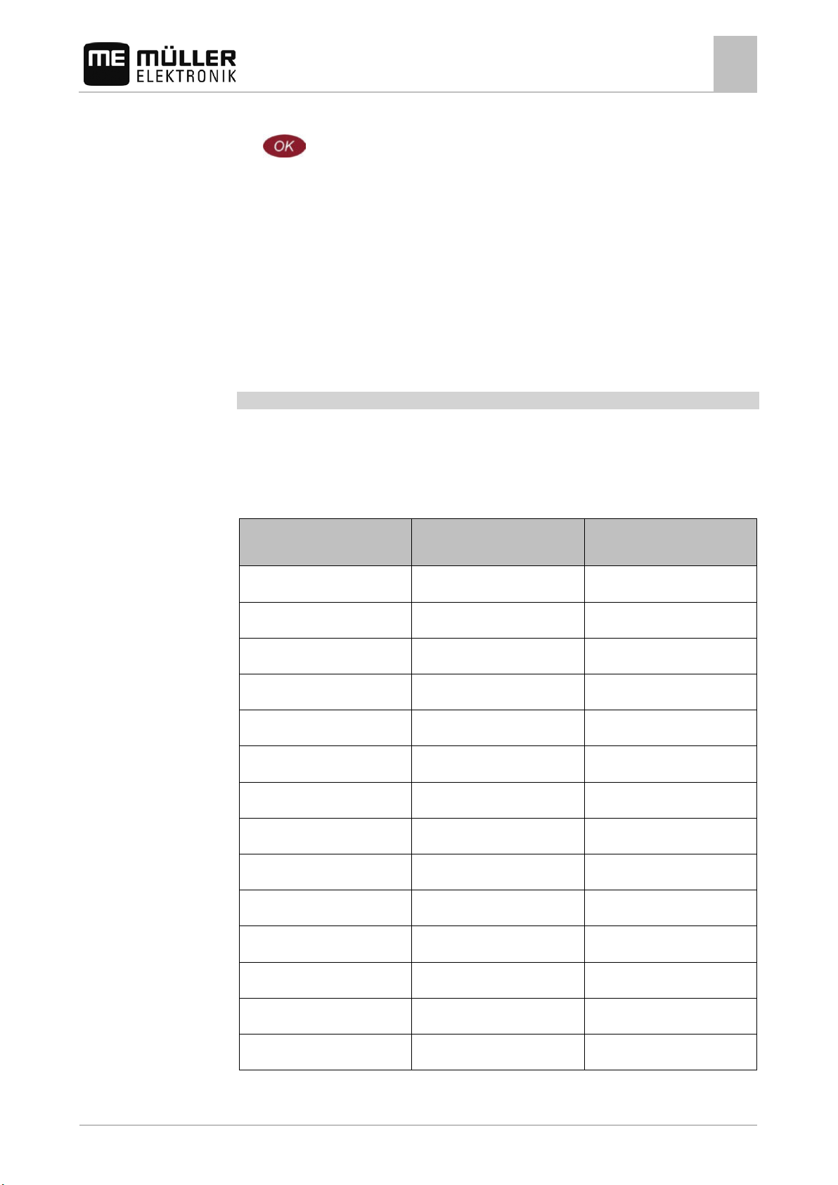
1. Switch to the Total nozzles screen:
⇨ The following screen appears:
The total number of nozzles is given in the header.
The numbers of the working widths are listed from left to right. Section 1 is the first section
on the left-hand side of the boom.
2.
3.
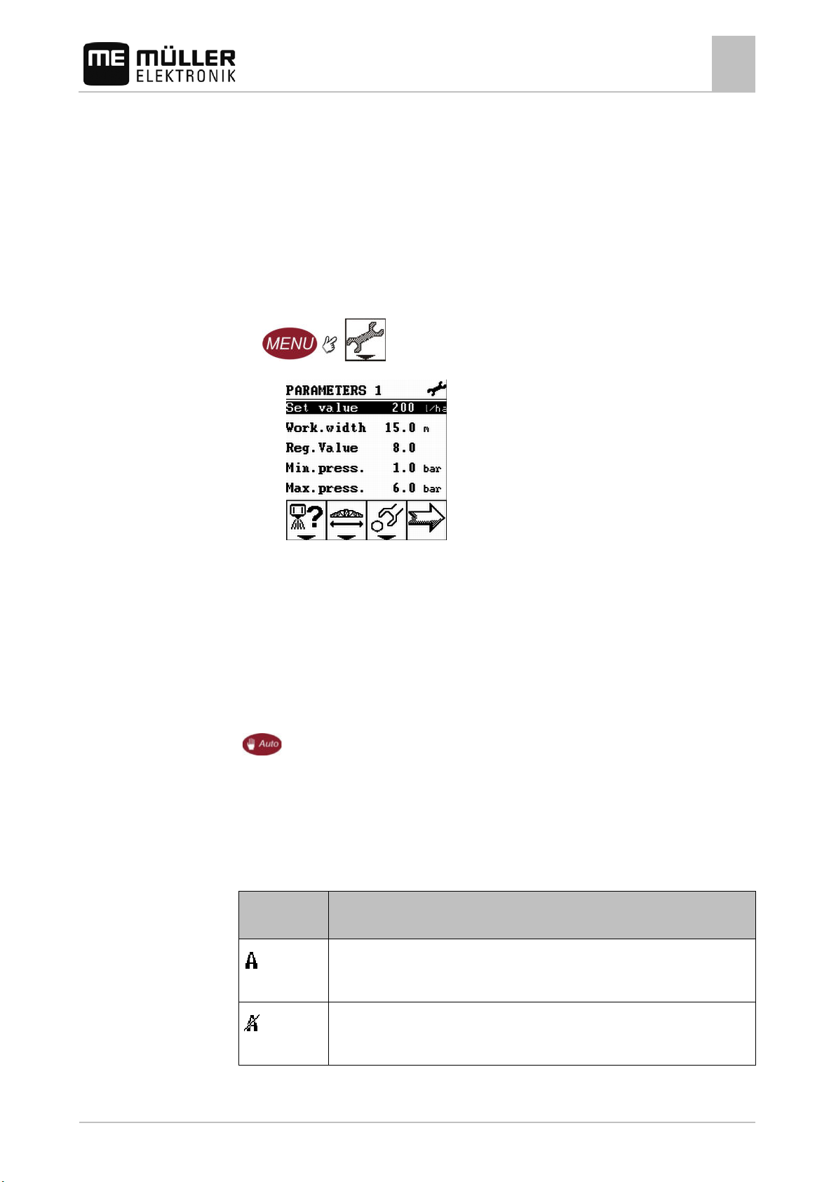
- Select the desired section.
- Confirm.
⇨ The following screen appears:
30 30283305-02-EN V5.20150204
Page 31
with ISO 10625
light pink
0075
0.3
green
015
0.6
yellow
02
0.8
blue
03
1.2
red
04
1.6
brown
05
2.0
white
08
3.2
light green
15
6.0
6.3.3
Preparing Spraylight for use
Entering sprayer parameters
6
4. Input the number of nozzles in the section in the Section screen.
5.
⇨ The new number of nozzles will be shown on the Total nozzles screen.
- Confirm.
Configuring the nozzle type
When using the Spraylight, you have the option to configure the type of nozzles which are mounted in
a section.
You can thus:
▪ Select the nozzle type.
▪ Calculate the output of the nozzles on your machine.
▪ Calculate the amount applied by the nozzles over a defined area.
Selecting the type of nozzle
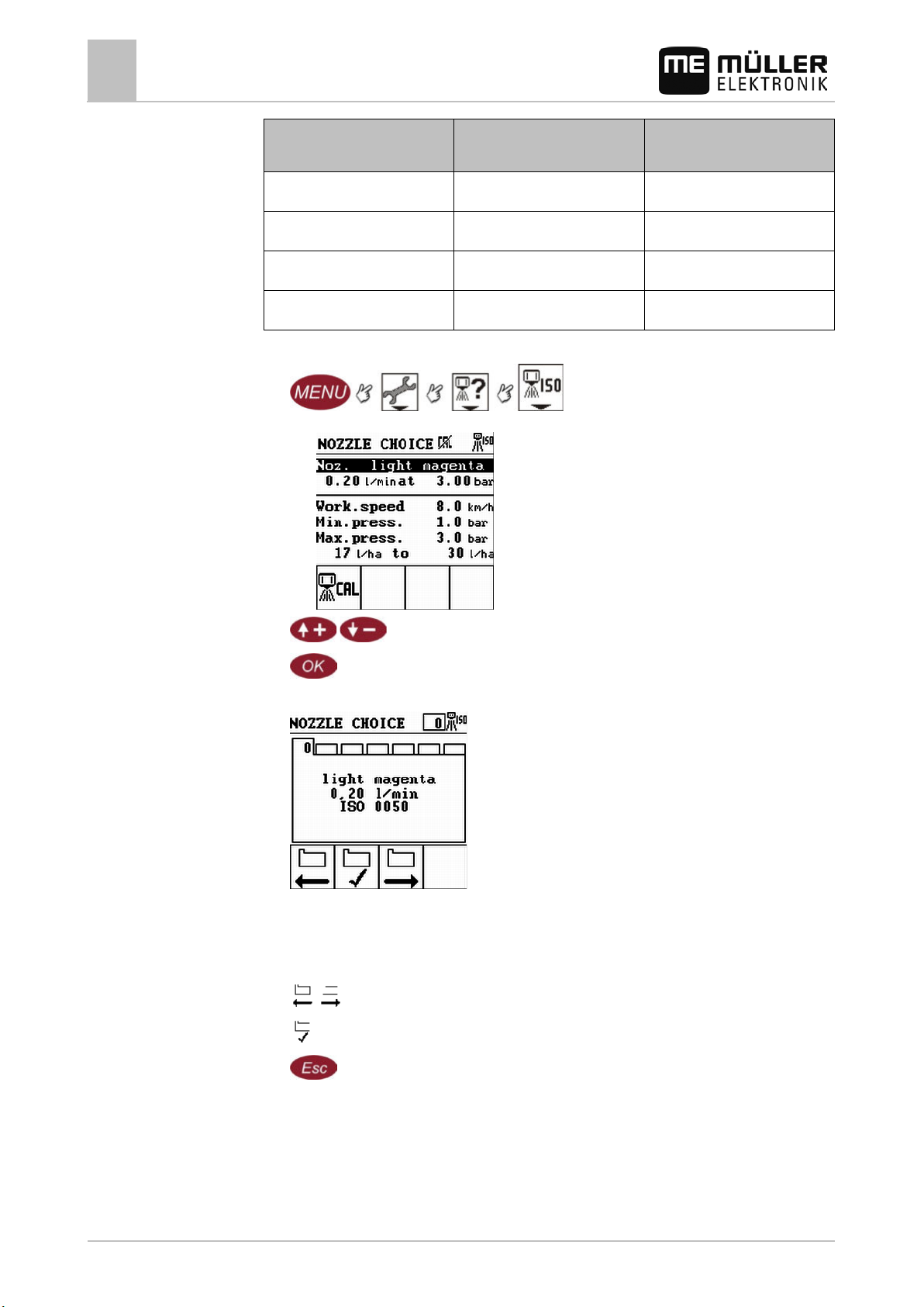
The nozzle choice list contains 14 standard nozzle types as defined by ISO 10625 and 4 userspecific, freely configurable nozzles types A, B, C and D.
The following table shows an overview of the nozzles, their color and output:
Nozzle color in accordance
ISO identifier Output in l/min. at 3 bar
light violet 0050 0.2
orange 01 0.4
violet 025 1.0
purple 035 1.4
grey 06 2.4
light blue 10 4.0
30283305-02-EN V5.20150204 31
Page 32
with ISO 10625
Nozzle B
-
Specific
Nozzle D
-
Specific
Procedure
Preparing Spraylight for use
6
Entering sprayer parameters
Nozzle color in accordance
ISO identifier Output in l/min. at 3 bar
Nozzle A - Specific
Nozzle C - Specific
1. Switch to the Nozzle choice screen:
⇨ The following screen appears:
2.
3.
- Highlight the Noz. (nozzle color) line.
- Confirm.
4. The following screen appears:
On the screen you can see:
- The standardized color of the nozzle,
- The standardized output of the nozzle,
- The standardized ISO number of the nozzle.
Select the desired nozzle type.
5.
6.
Confirm your choice.
7.
- Exit the screen.
⇨ The selected nozzle with the calculated application rate appears in the Nozzle choice
screen.
⇨ You have selected a nozzle type.
You can now evaluate the output and amount applied by the selected nozzle under different
conditions.
32 30283305-02-EN V5.20150204
Page 33
Procedure
Preparing Spraylight for use
Entering sprayer parameters
6
Calculating the output and amount applied by the nozzles on your machine
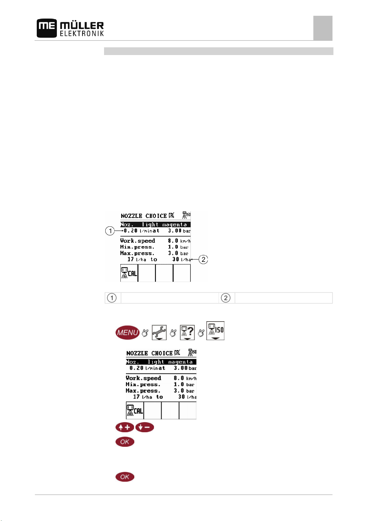
On the Nozzle choice screen, you can calculate how much you can apply with the selected nozzle.
This calculation should help you find the nozzle that is appropriate for your task.
The screen includes three parameters which you can configure yourself. Your inputs for these
parameters have no impact on the application. These values are used to calculate the application
amount and nozzle output.
Parameters in the Nozzle choice screen:
▪ Working speed
▪ Minimum pressure value
▪ Maximum pressure value
The pressure range defined by the pressure values should always be within the specification
defined by the nozzle manufacturer.
In addition to these three parameters, the following parameters are taken into consideration when
calculating nozzle output:
▪ Type of nozzle
▪ Working width of sprayer
The calculation results can be seen on the Nozzle choice screen:
Nozzle choice
Nozzle performance in liters per minute
Nozzle application amount in liters per minute
1. Switch to the Nozzle choice screen:
⇨ The following screen appears:
2.
3.
- Mark the desired parameter.
- Confirm.
⇨ The data input screen appears.
4. Input the desired value for a parameter in the data input screen.
5.
30283305-02-EN V5.20150204 33
- Confirm.
Page 34
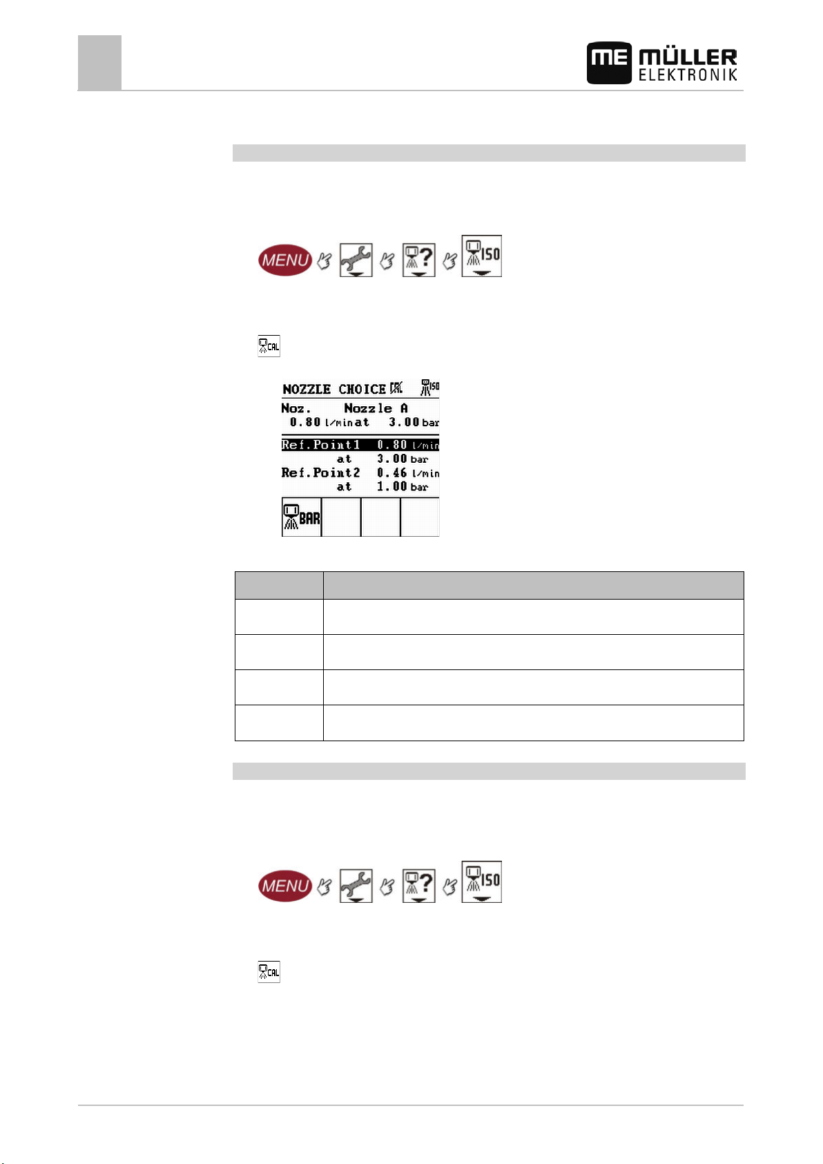
Parameter
Meaning
at
Pressure when maximum output was measured
Ref.Point2
Minimum output of the nozzle
Procedure
Procedure
Preparing Spraylight for use
6
Entering sprayer parameters
⇨ The calculated output of the nozzle is shown on the Nozzle choice screen.
Calibrating non-ISO compliant nozzles
if you install a non-ISO compliant nozzle, or if you notice that your nozzles perform differently than
that stipulated under ISO norms, you can re-calibrate the nozzles.
1. Switch to the Nozzle choice screen:
2. Select the nozzle type. See Chapter Selecting the type of nozzle [➙ 31].
Select one of the nozzles from types A, B, C or D.
3.
- Press.
⇨ The following screen appears:
4. Configure the nozzle. See the Table in these Operating Instructions.
Ref.Point1 Maximum output of the connected nozzle
at Pressure when minimum output was measured
Recalibrating a nozzle when worn
Even when you are using ISO-compliant nozzles, the output of the nozzle may change due to wear.
In this instance, you can calibrate an ISO nozzle and set a new output value.
1. Switch to the Nozzle choice screen:
2. Select the nozzle type. See Chapter Selecting the type of nozzle [➙ 31].
Select the nozzle that you want to calibrate.
34 30283305-02-EN V5.20150204
3.
- Press.
Page 35
Preparing Spraylight for use
Entering sprayer parameters
6
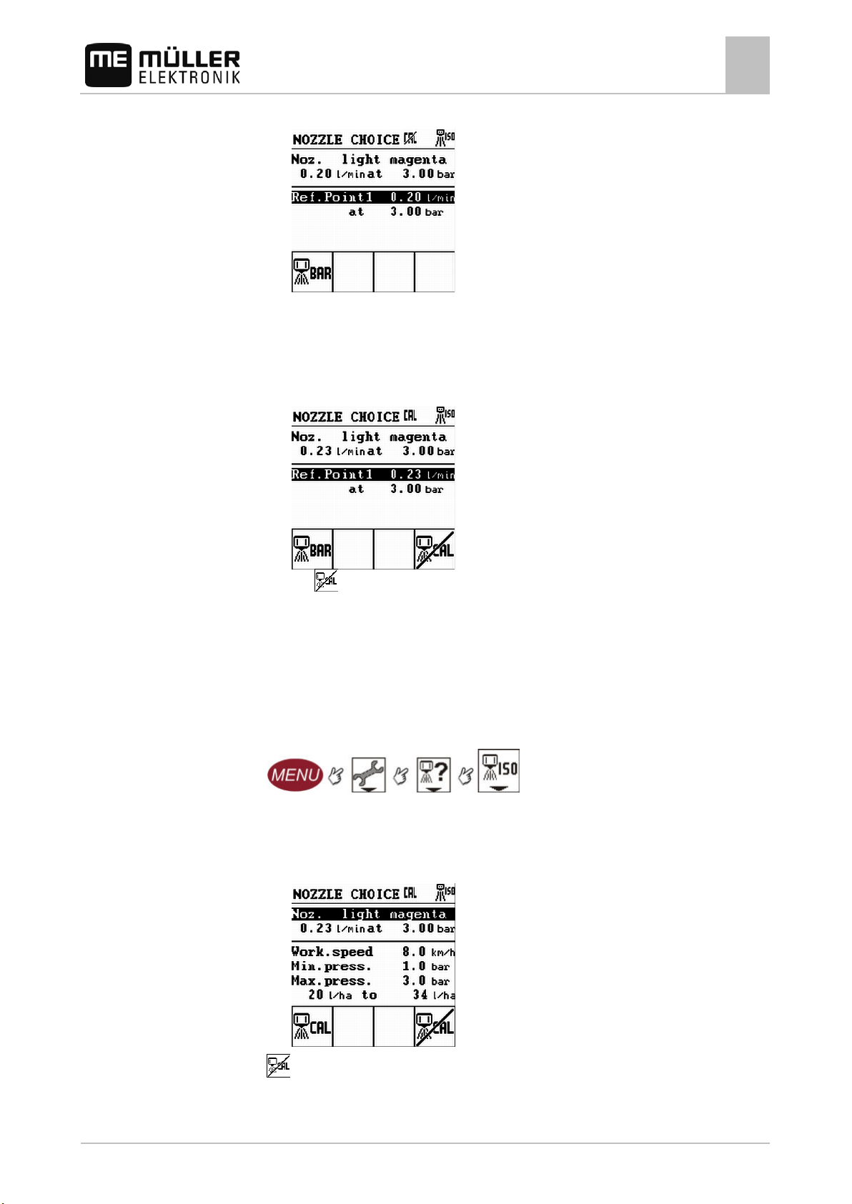
⇨ The following screen appears:
4. Highlight the Ref.Point1 line.
5. Input the current output of the nozzle at 3 bar.
You determine the output of the nozzle by measuring the applied amount from one nozzle in a
single minute using a measurement cup at a pressure of 3 bar.
⇨ The following screen appears:
Procedure
The
icon tells you that the selected nozzle was re-configured and is no longer ISO-
compliant.
⇨ You have calibrated a nozzle.
Restoring factory settings
You can reset a newly calibrated ISO nozzle to its ISO settings.
1. Switch to the Nozzle choice screen:
2. Select the nozzle type. See Chapter Selecting the type of nozzle [➙ 31].
Select a nozzle which you have calibrated to a new value and which you want to reset to its ISO
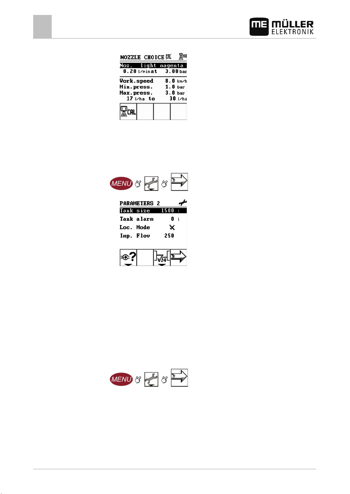
settings.
⇨ The selected nozzle will appear on the "Nozzle choice" screen:
3.
- Reset nozzle to ISO settings.
If this function icon does not appear, the nozzle is already calibrated to be ISO-compliant.
30283305-02-EN V5.20150204 35
Page 36
6.3.4
When to enter?
Procedure
Preparing Spraylight for use
6
Entering sprayer parameters
⇨ The following screen appears:
⇨ You have reset the re-configured nozzle to its ISO settings.
Inputting tank size
▪ Prior to initial startup.
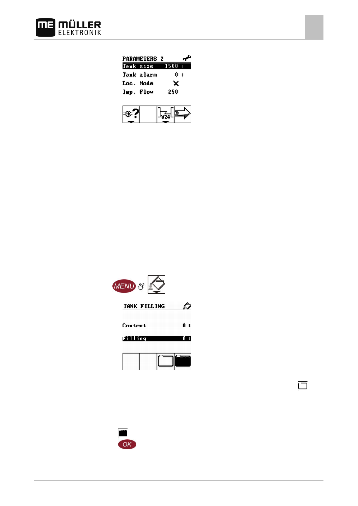
1. Switch to the Parameters 2 screen:
⇨ The following screen appears:
2. Input the size of your tank in the Tank size line.
⇨ You have input the tank size.
6.3.5
Setting a tank alarm
If the amount of spray fluid in the tank is lower than the value given here, the tank alarm is triggered:
▪ A pop-up window appears.
▪ A beep sounds.
To deactivate this function:
Procedure
▪ Enter value 0 in the Tank alarm line.
1. Switch to the Parameters 2 screen:
36 30283305-02-EN V5.20150204
Page 37
6.4
6.4.1
Preparing Spraylight for use
Tank filling
6
⇨ The following screen appears:
2. Input the amount to trigger the tank alarm when this amount is undercut in the Tank alarm line.
Preconditions
⇨ You have activated the tank alarm.
Tank filling
You must always input the amount poured in when filling the tank on the sprayer. This process is
called: Tank filling.
There are two ways to fill the tank:
▪ Filling up the tank without TANK Control
▪ Filling up the tank with TANK-Control
Filling up the tank without TANK Control
If you fill the tank without Tank Control, you must input the filled amount manually into Spraylight.
You have input the tank size correctly.
1. Switch to the Tank filling screen:
⇨ The following screen appears:
The Content parameter gives the current content of the tank.
2. If the actual tank is empty, but Spraylight indicates that this is not yet empty, then set
Content to 0
⇨ The Content parameter is set to 0 liters:
3. Fill the tank.
When filling the tank, you have the following options:
- At the terminal, input that the tank is now full.
a)
b)
- Activate the highlighted Filling line.
In the data input screen, input the amount which will be in the tank after filling.
4. The value of the Content parameter changes.
30283305-02-EN V5.20150204 37
Page 38
NOTICE
◦ Calibrate the flow meter very precisely.
6.4.2
6.5
calibrate?
Methods
Preparing Spraylight for use
6
Calibrating the flow meter
⇨ You have filled the tank.
Filling up the tank with TANK Control
TANK-Control is a measurement system that constantly measures and displays the tank content.
If TANK-Control is connected to the sprayer and is configured for use with TANK-Control, you need
not enter anything when filling the tank.
Procedure
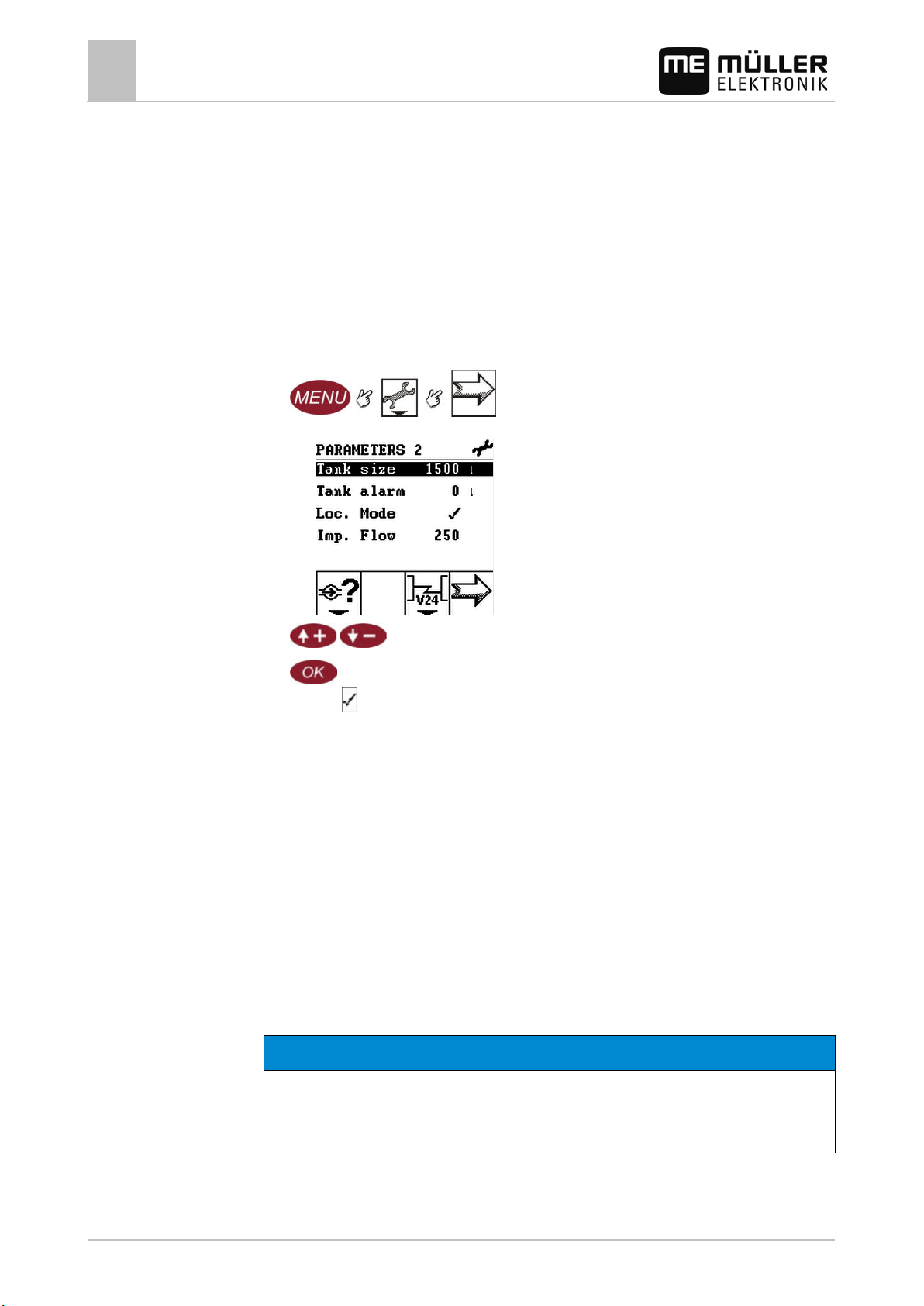
To activate TANK-Control:
TANK-Control is connected.
1. Change to Parameters 2 screen:
⇨ The following screen appears:
2.
3.
- Mark the Tank-Control line.
- Activate the Tank-Control parameter.
⇨ The
icon will appear next to the Tank Control parameter.
⇨ TANK-Control is activated.
When should you
Calibrating the flow meter
Because the number of pulses per liter can change during the lifespan of a flow meter, calibration
must be carried out in the following cases:
▪ Prior to initial startup.
▪ At the start of each season.
▪ When you detect deviations between the amount actually sprayed and the amount displayed.
▪ When you have replaced or repaired the flow meter.
There are two ways you can calibrate the flow meter:
▪ The tank method – it is time-consuming, but precise.
▪ The nozzle method – it is not as precise as the tank method, but is less time-consuming.
Imprecise calibration
If the calibration is imprecise, the calculations will be very inexact and the application imprecise.
38 30283305-02-EN V5.20150204
Page 39
6.5.1
Mode of operation
Preparing Spraylight for use
Calibrating the flow meter
6
Preconditions
Calibrating the flow meter with the tank method
In the tank method a large quantity of water will be sprayed from the tank over a specific time.
The flow meter measures the pulses during this time.
After the application, you must enter the quantity of water that has been sprayed.
The computer works out the number of pulses per liter.
All sections are selected.
Manual mode is activated (the
You have filled the tank with clean water. For this you need several hundred liters of water.
You have the option of weighing the entire trailer or measuring the volume of water applied with
another method.
Pump is switched on.
1. Make sure that all preconditions are fulfilled!
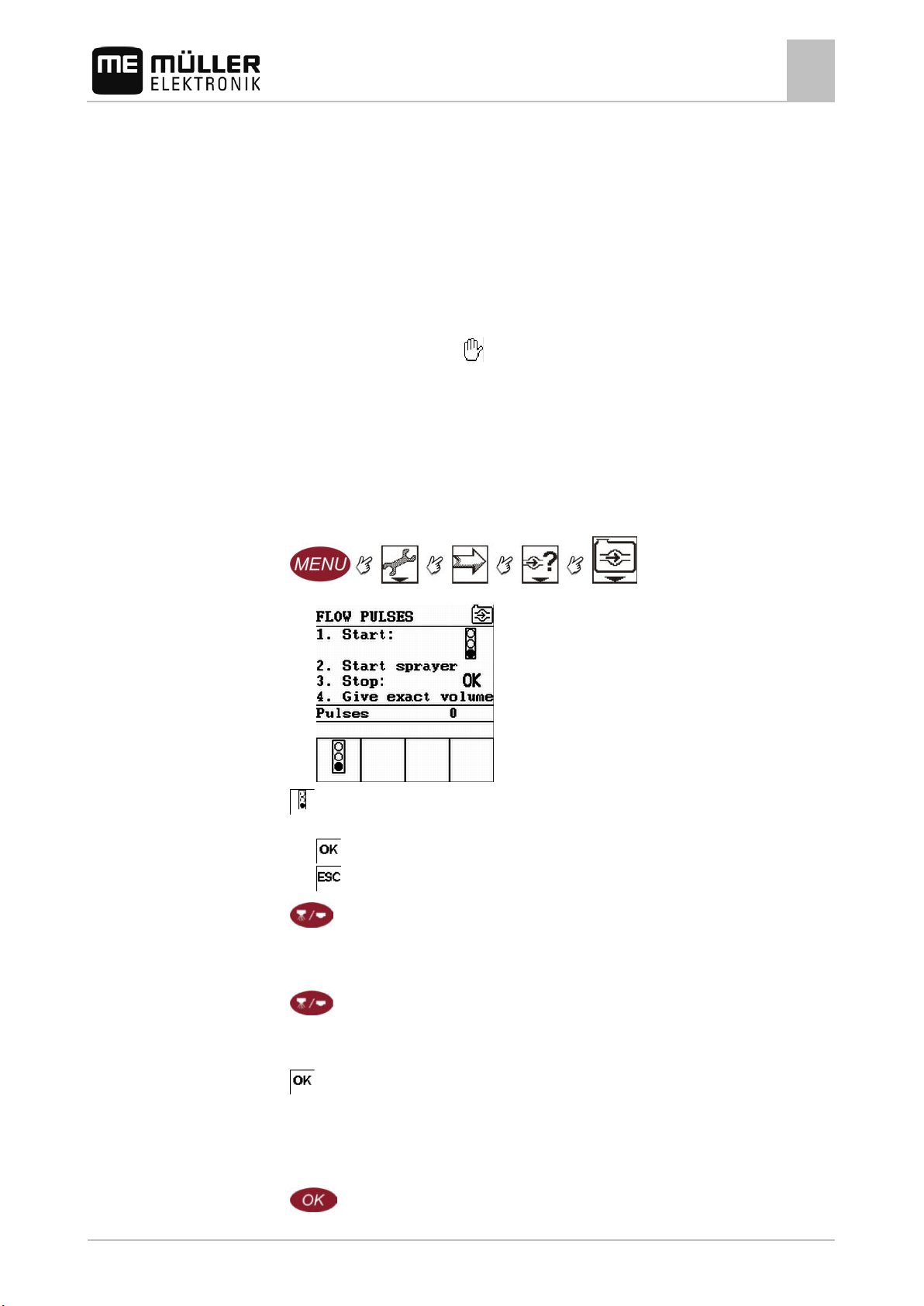
2. Switch to the Flow pulses screen:
⇨ The following screen appears:
icon appears on the work screen).
3.
- Start calibration.
⇨ The following function icons appear:
- Stop calibration.
- Abort calibration.
4.
- Start application.
⇨ During application, the number of pulses is counted on the Flow pulses screen.
5. Wait until a few hundred liters have been applied.
6.
- Stop applying.
⇨ The application will be stopped.
⇨ No pulses are counted on the display.
- Stop calibration.
7.
⇨ The highlighted Volume line appears in the Flow pulses screen.
8. Determine the quantity applied.
9. Check that the Volume line is highlighted.
10.
- Select the Volume line.
30283305-02-EN V5.20150204 39
Page 40
6.5.2
Mode of operation
Preparing Spraylight for use
6
Calibrating the flow meter
⇨ The data input screen appears.
11. Input the amount applied in liters.
Preconditions
12.
13.
- Confirm.
- Exit the screen.
⇨ You have calibrated the flow meter with the tank method.
Calibrating the flow meter with the nozzle method
When calibrating the flow meter using the nozzle method, you determine the average quantity of the
liquid applied through a nozzle in a specific time.
When calibrating using this method, you must apply clean water over the entire working width and
measure the applied quantity on different nozzles using a measuring cup.
The flow meter measures the pulses during this time.
When you have finished the application, you must enter how much water was applied on average by
one nozzle in one minute.
The computer works out the number of pulses per litre.
You have prepared a measuring cup you can use to measure the quantity sprayed.
You have prepared a stopwatch to be able to count one minute precisely.
All of the sections are open, and the sprayer can apply over the entire working width.
Manual mode is activated (the
icon appears on the work screen).
The tank is filled with clear water.
The set working width is correct.
The number of nozzles per section and the number of sections are entered correctly.
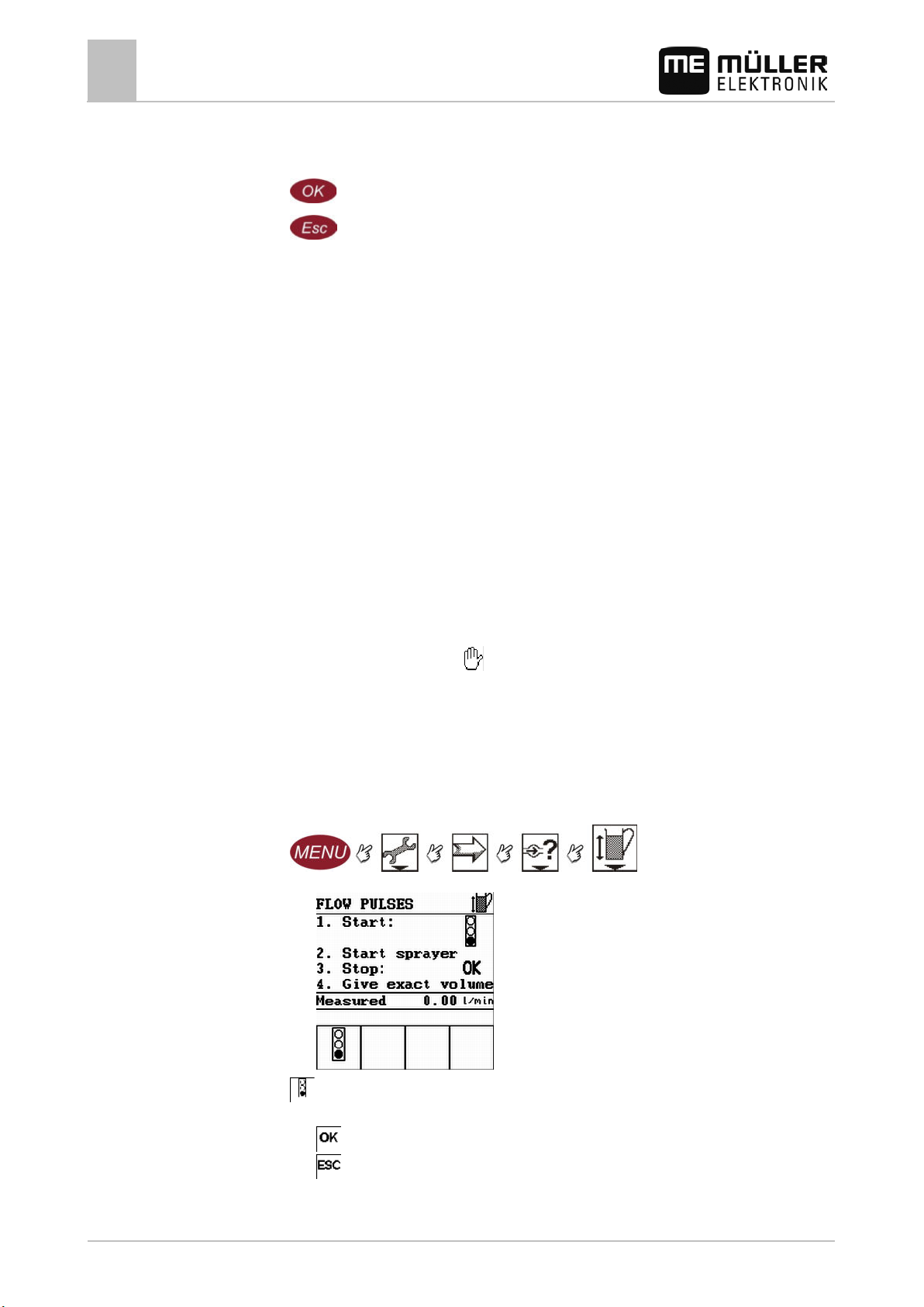
1. Ensure that all prerequisites have been fulfilled.
2. Switch to the Flow pulses screen:
⇨ The following screen appears:
3.
- Start calibration.
⇨ The following function icons appear:
40 30283305-02-EN V5.20150204
- Stop calibration.
- Abort calibration.
Page 41
6.5.3
Procedure
6.6
Preparing Spraylight for use
Calibrating the wheel sensor
6
4. - Start application.
⇨ During application, the number of litres applied per minute is counted on the Flow pulses
screen.
5. Go to one nozzle and for 60 seconds carefully collect the water sprayed by using the measuring
beaker prepared. Write down the quantity.
We recommend that you count the average from multiple nozzles.
6.
- Stop applying.
⇨ The application will be stopped.
⇨ No further litres are counted on the display.
7.
- Stop calibration.
⇨ The volume line appears on the Flow pulses screen.
8.
- Select the Volume line.
⇨ The Volume screen appears.
9. Enter the average measured volume in litres.
10.
11.
⇨ You have calibrated the flow meter with the nozzle method.
- Confirm.
- Exit screen.
Manually entering the number of pulses per liter for the flow meter
If you know the precise number of pulses per liter for the flow meter, you can enter this value
manually.
1. Switch to the Parameters 2 screen:
⇨ The following screen appears:
2. Enter the number of pulses per liter in the Imp. Flow line.
⇨ The number of pulses per liter input appears in the Imp. Flow line.
Calibrating the wheel sensor
▪ When the speed shown on the work screen is incorrect.
▪ When the traveled route shown on the work screen is incorrect.
30283305-02-EN V5.20150204 41
Page 42
NOTICE
◦ Calibrate the wheel sensor very precisely.
Preconditions
Preparing Spraylight for use
6
Calibrating the wheel sensor
Imprecise calibration
The speed cannot be precisely determined with an incorrectly calibrated wheel sensor.
As a result all the calculations of the area sprayed, the route traveled and the volume applied will be
highly imprecise.
6.6.1
Determining pulses per 100 meters
When calibrating the wheel sensor with the 100m method, you determine the number of pulses
received by the sensor over a distance of 100 meters.
To make sure that the wheel sensor functions correctly, at least 185 pulses must be received every
100 meters.
When the number of pulses is known, Spraylight can calculate the actual speed.
Wheel sensor is mounted.
All wheel sensor magnets are fully functional.
A distance of 100m has been measured and marked. The distance must correspond to the field
conditions. It should therefore lead over a meadow or a field.
The tractor with connected machine is ready for a 100m drive and is at the start of the marked
distance.
1. Make sure that all preconditions are fulfilled!
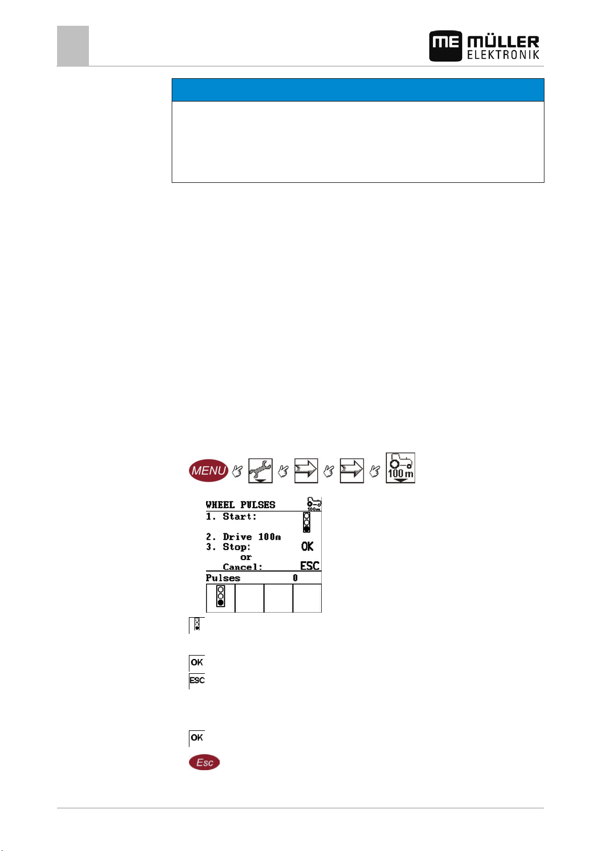
2. Switch to the WHEEL PULSES screen:
⇨ The following screen appears:
42 30283305-02-EN V5.20150204
3.
- Start calibration.
4. The following function icons appear:
- Stop calibration.
- Abort calibration.
5. Drive the previously measured 100m distance and stop at the end.
⇨ During the drive, the currently determined pulses are displayed.
- Stop calibration.
6.
7.
- Exit the screen.
⇨ You have calibrated the wheel sensor.
Page 43
6.6.2
6.7
Preconditions
Preparing Spraylight for use
Set limit values for the spray pressure
6
Manually entering the number of pulses for the wheel sensor
Procedure
If you know the number of pulses for the wheel sensor you can enter this number manually as well.
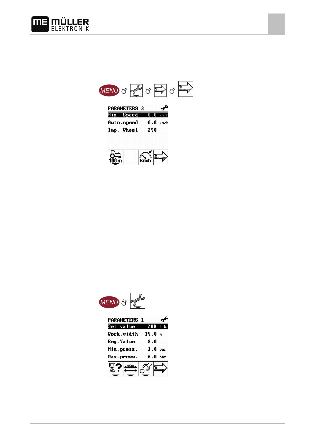
1. Change to Parameters 3 screen
⇨ The following screen will appear:
2. Enter the number of pulses in the Wheel.pls line.
⇨ You have manually entered the number of pulses.
Set limit values for the spray pressure
This setting defines a spray pressure range within which the spray pressure is optimal.
If the spray pressure is above or below the maximum limit values, an alarm will be triggered.
You can decide what limit values you want for yourself.
If no pressure sensor is installed on your sprayer, you must deactivate this function as follows:
▪ Enter value 0 in the min. pressure line.
▪ Enter value 0 in the max. pressure line.
A pressure sensor is fitted to the sprayer.
1. Make sure that all preconditions are fulfilled!
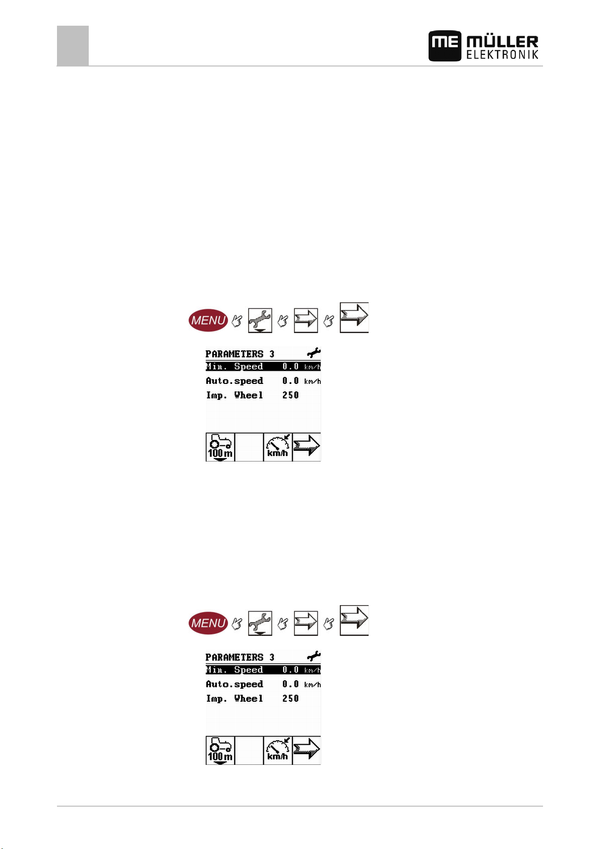
2. Switch to the Parameters 1 screen:
⇨ The following screen appears:
3. Input the minimum pressure in the Min.press. line.
4. Input the maximum pressure in the Max.press. line.
⇨ The new limit values appear in the Parameters 1 screen.
30283305-02-EN V5.20150204 43
Page 44
6.8
6.8.1
6.8.2
Procedure
Preparing Spraylight for use
6
Configuring Automatic mode
Configuring Automatic mode
Automatic mode controls the spray pressure automatically. For this, a set value must be reached.
To use automatic mode, you must configure the following parameters:
▪ Set value
▪ Reg.Value
▪ Working width
▪ Calibrate wheel sensor / pulses per 100m
Setting minimum working speed
If the machine speed drops below the minimum working speed, the following happens:
▪ Application stops automatically.
Procedure
1. Switch to the Parameters 3 screen:
⇨ The following screen appears:
2. Enter the minimum working speed in the Min. Speed line.
Entering 0 deactivates this function and Automatic mode.
⇨ The new value appears in the Parameters 3 screen.
Setting minimum automatic working speed
If the sprayer speed drops below the minimum automatic speed, the following happens:
▪ Spray pressure regulation is switched off.
1. Switch to the Parameters 3 screen
⇨ The following screen appears:
2. Input the minimum pressure in the Auto.speed line.
44 30283305-02-EN V5.20150204
Page 45
6.8.3
Mode of operation
Procedure
6.9
Preconditions
Preparing Spraylight for use
⇨ The new value appears in the Parameters 3 screen.
Triggering hydraulic valves
6
Setting the regulation value
In Automatic mode, the spray pressure of the nozzles is adapted to the current speed of the sprayer.
The adjustment should ensure that the volume of spray liquid that is applied is exactly what you
defined in the set value. The regulation value plays a decisive role in this.
The regulation value adjusts the regulation speed:
▪ The higher the regulation value, the faster the spray pressure is adjusted.
▪ The lower the regulation value, the more slowly the spray pressure is adjusted.
When setting the regulation value, take note of the following:
▪ If, during movement at constant speed, the current application volume jumps around the set
value, you must reduce the regulation value.
▪ If, when the speed changes, the application volume does not adjust to the set value quickly
enough, you must increase the regulation value.
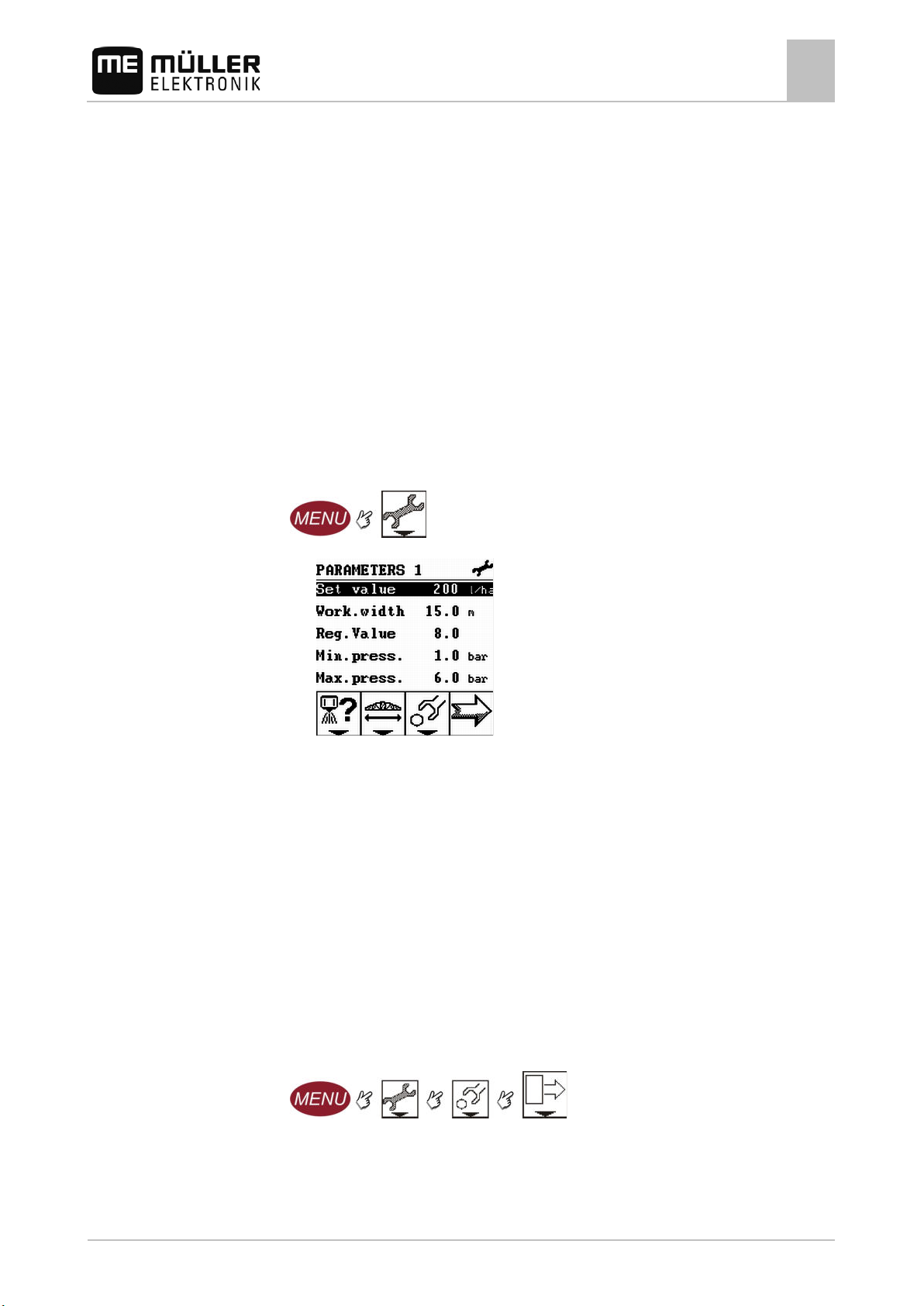
1. Switch to the Parameters 1 screen:
⇨ The following screen appears:
2. Input the desired regulation value in the Reg.Value line.
⇨ The new regulation value appears in the Parameters 1 screen.
Triggering hydraulic valves
According to configuration, several hydraulic valves can be connected to your terminal. In order for
these to be controlled you must assign a function button to each of the hydraulic valves.
When assigning a function button to a hydraulic valve, a function symbol for this hydraulic valve
appears on the work screen.
A service technician has already activated the hydraulic valve triggering in the service area of the
Spraylight.
30283305-02-EN V5.20150204 45
1. Make sure that all preconditions are fulfilled!
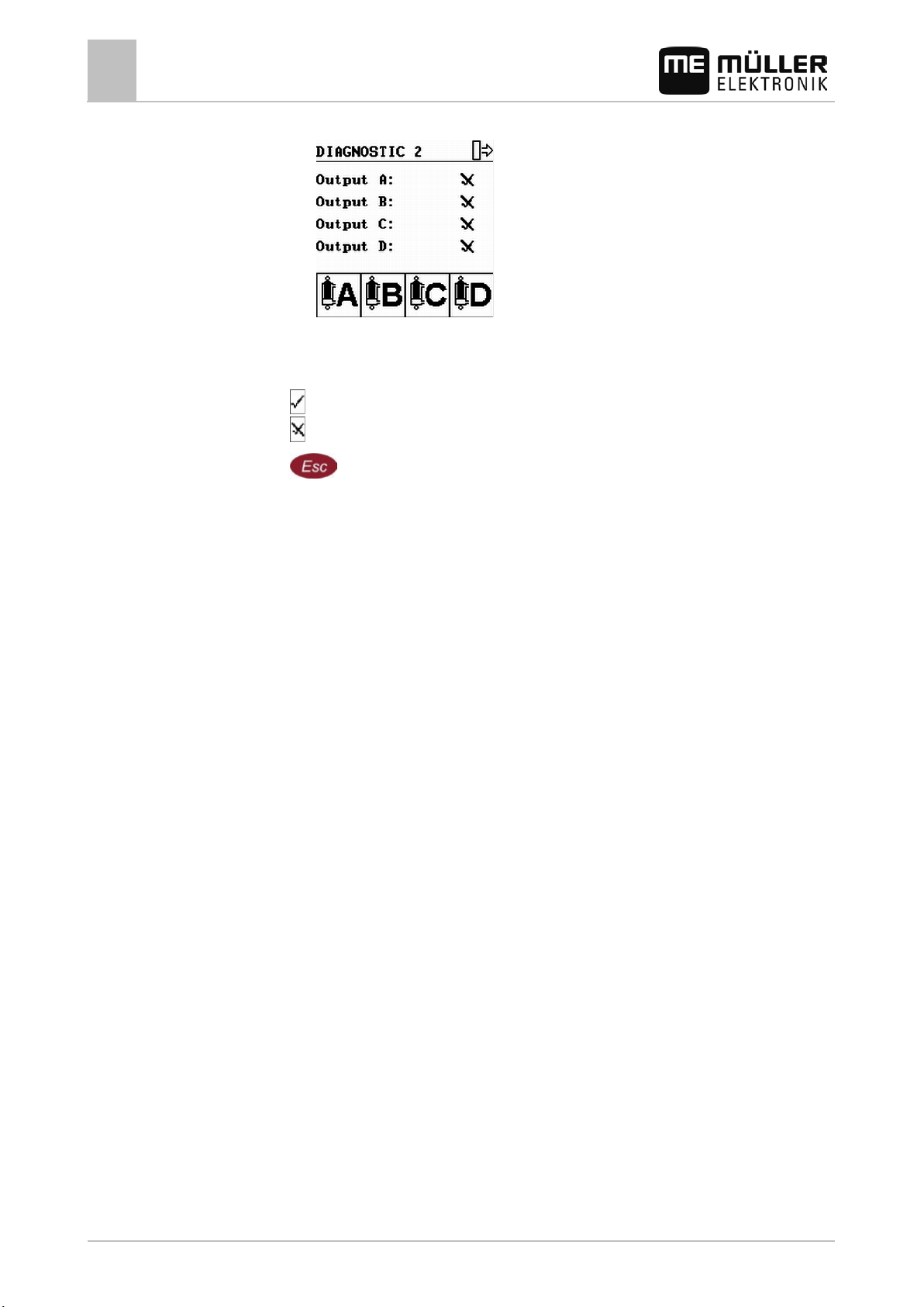
2. Switch to the Diagnosis 2 screen:
Page 46
6.10
Preparing Spraylight for use
6
Configuring the communication with an ISOBUS terminal
⇨ The following screen appears:
Each output corresponds to a hydraulic valve.
3. Press the function keys to activate the desired hydraulic valves.
Besides the names of the outputs, the following icons appear:
- Hydraulic valve is activated.
- Hydraulic valve is deactivated.
Procedure
4.
- Exit the Diagnosis 2 screen.
⇨ You have activated the desired hydraulic valves.
Configuring the communication with an ISOBUS terminal
Spraylight is capable of exchanging data with an ISOBUS terminal.
Advantages:
▪ You can achieve site-specific metering by importing the target rates from a prescription map.
– For Spraylight software version 02.00.10 via LH5000
– As of Spraylight software version 02.00.13 via LH5000 or ASD
▪ You can control the sections automatically, e.g to prevent overlaps.
The ISOBUS terminal can provide the corresponding information through the V24 interface.
1. Configure the V24 interface [➙ 55].
2. Connect Spraylight to an ISOBUS terminal. You can read how to do this in the operating
instructions for the terminal.
46 30283305-02-EN V5.20150204
Page 47
work screen
The spray pressure will be regulated so that the set value is achieved.
Sprayer can apply. Spray pressure is not regulated.
7
7.1
7.2
Controls
7.2.1
Applying the device in the field
Entering the set value
7
Applying the device in the field
In this chapter, you will find out how you can work with the sprayer during application with the help of
the Spraylight.
Entering the set value
The set value is the amount of spray liquid you want to apply per hectare.
Procedure
You must enter this set value in order to enable Spraylight to control application automatically.
1. Switch to the Parameters 1 screen:
⇨ The following screen appears:
2. Enter the application amount in the Set value line.
⇨ The set value entered appears in brackets on the work screen.
Controlling application
Spraylight lets you work in two modes:
▪ in automatic mode
▪ in manual mode
Switching between manual and automatic mode
Using Automatic mode
In Automatic mode, Spraylight controls the spray pressure and the sections' main switch so the set
value is reached.
30283305-02-EN V5.20150204 47
You are in automatic mode when one of the following icons appears in the work screen:
Icon on the
Meaning
Sprayer can apply.
The speed of the sprayer is below Auto.speed.
Page 48
work screen
Sprayer switches off automatically.
Controls
7.2.2
Controls
7.2.3
Preconditions
Applying the device in the field
7
Controlling application
Mode of operation
Preconditions
Icon on the
Meaning
The speed of the sprayer is below Min. Speed.
The spray pressure will be adjusted automatically in the following cases:
▪ Speed of the sprayer has changed.
▪ The number of selected sections has changed.
▪ You have changed the set value manually.
The speed and precision with which the set value will be adjusted depends on the value of the
Reg.Value parameter.
You can change the set value manually while driving in Automatic mode.
▪ Set value has been entered
▪ Flow meter is calibrated
▪ Wheel sensor is calibrated
▪ Working width is set
▪ The speed of the sprayer is higher than the set Auto.speed.
▪ The Reg.Value parameter has been set.
Increase the set value by 10%
Reduce the set value by 10%
Set the set value to 100%
Using Manual mode
You are in Manual mode if the icon appears on the work screen.
In manual mode, you must control the spray pressure yourself.
You can read the current spray pressure on the work screen.
Manually increase the spray pressure
Manually decrease the spray pressure
Starting application
The tractor with the sprayer is on the field.
Spraylight is configured.
The spray boom is folded out.
48 30283305-02-EN V5.20150204
1. Make sure that all preconditions are fulfilled!
- Switch on Spraylight.
2.
Page 49
7.2.4
7.3
7.4
7.5
Procedure
Applying the device in the field
Switching off sections
7
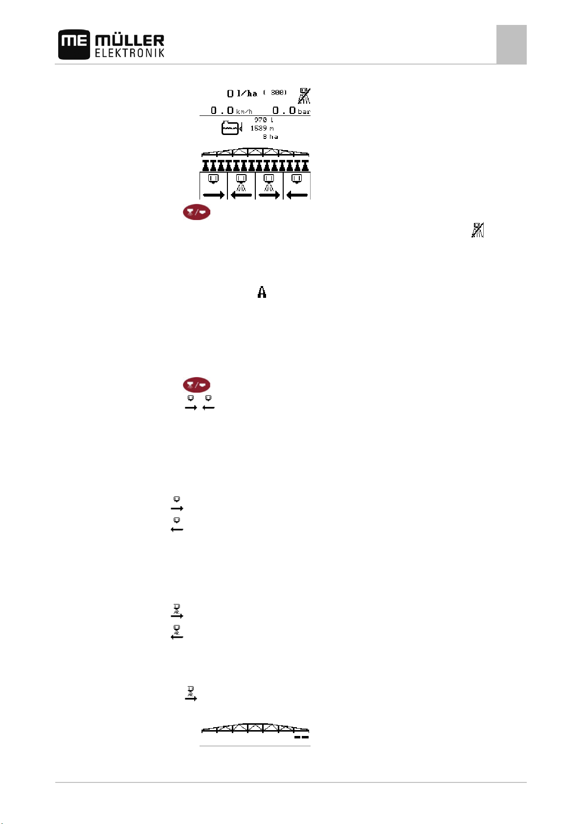
⇨ The work screen appears:
Controls
3.
- Start application.
⇨ The sprayer is ready for application. Because the sprayer is not moving, the
appears on the work screen.
4. Drive off and exceed the minimum Autospeed.
⇨ As soon as you exceed the minimum Autospeed, the sprayer will begin application. During
application, the
icon appears on the work screen.
⇨ You have started application.
Stopping application
You can stop application in the following ways:
▪
▪
- stop application.
- switch off all sections.
▪ Move slower than the set minimum speed.
Switching off sections
Sections can only be switched off inwards from the outermost section.
Switch off sections from left to right
icon
Controls
Pressing a function key several times switches off a section each time.
Selecting sections
Selecting sections when all sections are switched off
Switch off sections from right to left
Switch on sections from left to right
Switch on sections from right to left
1. - Select a section on the far right.
⇨ The icon for a selected section appears on the right side of the boom display:
30283305-02-EN V5.20150204 49
Page 50
7.6
7.6.1
7.6.2
Controls
7.6.3
Applying the device in the field
7
Working in localized mode
2. - Switch on further sections from right to left.
⇨ A further section is selected:
3. Proceed until the desired number of sections is selected.
Working in localized mode
"Localized mode" is designed for the targeted treatment of small weed infestations.
In contrast to normal mode, in localized mode you can switch individual sections on and off, even
when they are not adjacent to one another.
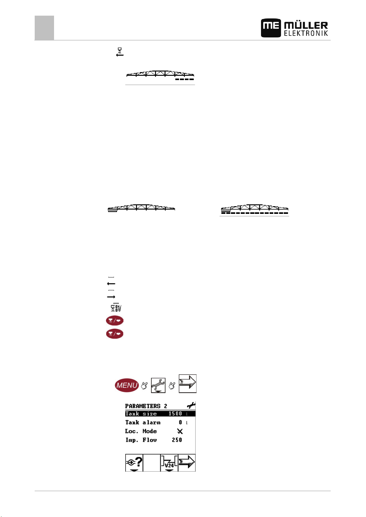
Work screen in localized mode
The work screen in localized mode differs slightly from the normal work screen.
▪ In the boom display a cursor bar appears below the boom:
▪ Three function icons appear in the function icons area for operating the sections.
Selecting and switching off sections in localized mode
Regardless of whether the sprayer is applying, you can move the cursor bar below any section and
change the section's state.
Procedure
Move cursor bar to the left
Move cursor bar to the right
Select or switch off a marked section
When certain sections are selected, application then starts on these sections
When no sections are selected, application then starts on all sections
Activating localized mode
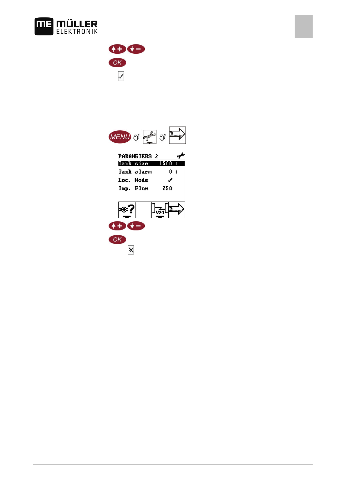
1. Switch to the Parameters 2 screen:
⇨ The following screen appears:
50 30283305-02-EN V5.20150204
Page 51
7.6.4
7.7
7.7.1
Applying the device in the field
Documenting work results
7
2. - Highlight the Loc. Mode line.
Procedure
3.
4. The
- Activate Localized mode.
icon appears alongside the Loc. Mode parameter.
⇨ Localized mode is activated.
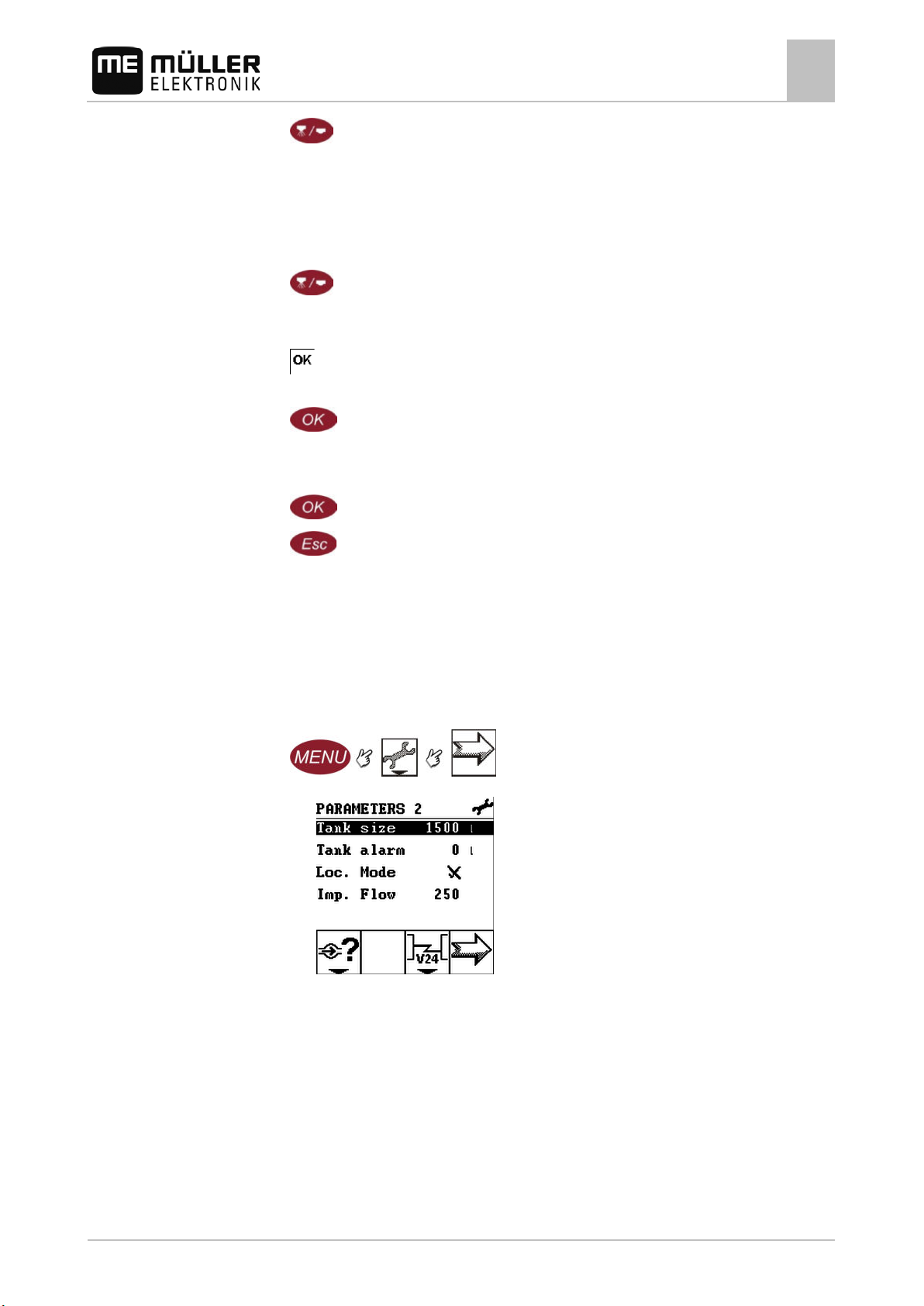
Deactivating localized mode
1. Switch to the Parameters 2 screen:
⇨ The following screen appears:
2.
- Highlight the Loc. Mode line.
3.
- Deactivate Localized mode.
⇨ The
icon appears alongside the Loc. Mode parameter.
Localized mode is deactivated.
⇨ Normal mode is activated again.
Documenting work results
You can document and evaluate the work results on two screens:
▪ Screen Totals
▪ Screen Daily counter
Both screens contain the following information:
▪ Volume – applied volume.
▪ Area – area processed.
▪ Distance – distance driven during the application.
▪ Time – Total application time.
The Totals screen
The total counter automatically documents all work results since the initial commissioning of the
Spraylight.
30283305-02-EN V5.20150204 51
Page 52
displayed.
documenting the current work.
7.7.2
Controls
7.7.3
Path
Applying the device in the field
7
Documenting work results
The Totals screen
Path
The Daily counter screen
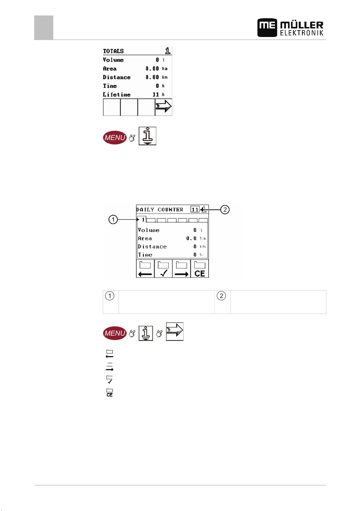
DAILY COUNTER – document the work results within the period since the daily counter was
activated until another daily counter is activated.
Spraylight has 20 daily counters.
Daily counter
Displayed daily counter
Number of daily counters whose results are
Activated daily counter
Number of daily counters which are
Mode of operation
52 30283305-02-EN V5.20150204
Show previous daily counter
Show next daily counter
Activate daily counter shown
Delete the contents of the daily counter shown
Documenting work results with a daily counter
All work you carry out is documented by the active daily counter.
You can change the number of the active daily counter manually. If you do not change the number of
the active daily counter, Spraylight sets the counter to continue counting on the next day.
Page 53
WARNING
valves!
Procedure
After work:
7.8
Controls
Applying the device in the field
Working with hydraulic valves
7
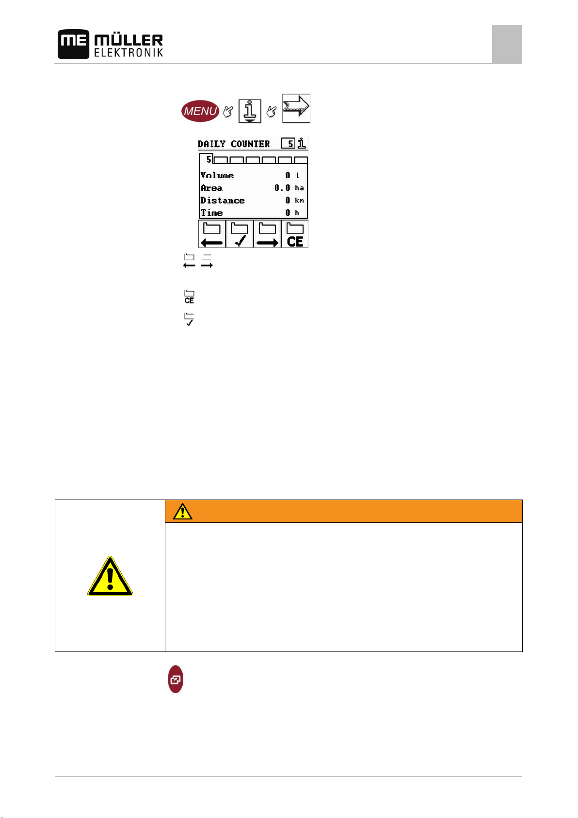
1. Switch to the Daily counter screen:
⇨ The following screen appears:
2.
- Select the daily counter you want to activate.
3. If this daily counter already contains work results, you can:
- Delete the contents of the daily counter shown.
4.
- Activate the daily counter shown.
⇨ The number of the activated daily counter changes in the header.
5. Start work.
1. Note the documented work results.
2. Activate a daily counter again before the next deployment.
Working with hydraulic valves
Hydraulic valves allow additional machines and functions to be connected to the sprayer.
If you connect hydraulic valves to the Spraylight and configure them, you can control the connected
devices with the help of the Spraylight.
Risk of injury
Actuating a hydraulic valve can cause connected machines and machinery components to move.
This may cause danger for you and for persons in direct proximity to the machine.
◦ Familiarize yourself with the machine functions which are triggered by the valves.
◦ Read the warning notices in the operating instructions for the machines connected to the
hydraulic valve before actuating a hydraulic valve!
◦ Follow the instructions in the operating instructions for the machines connected to the hydraulic
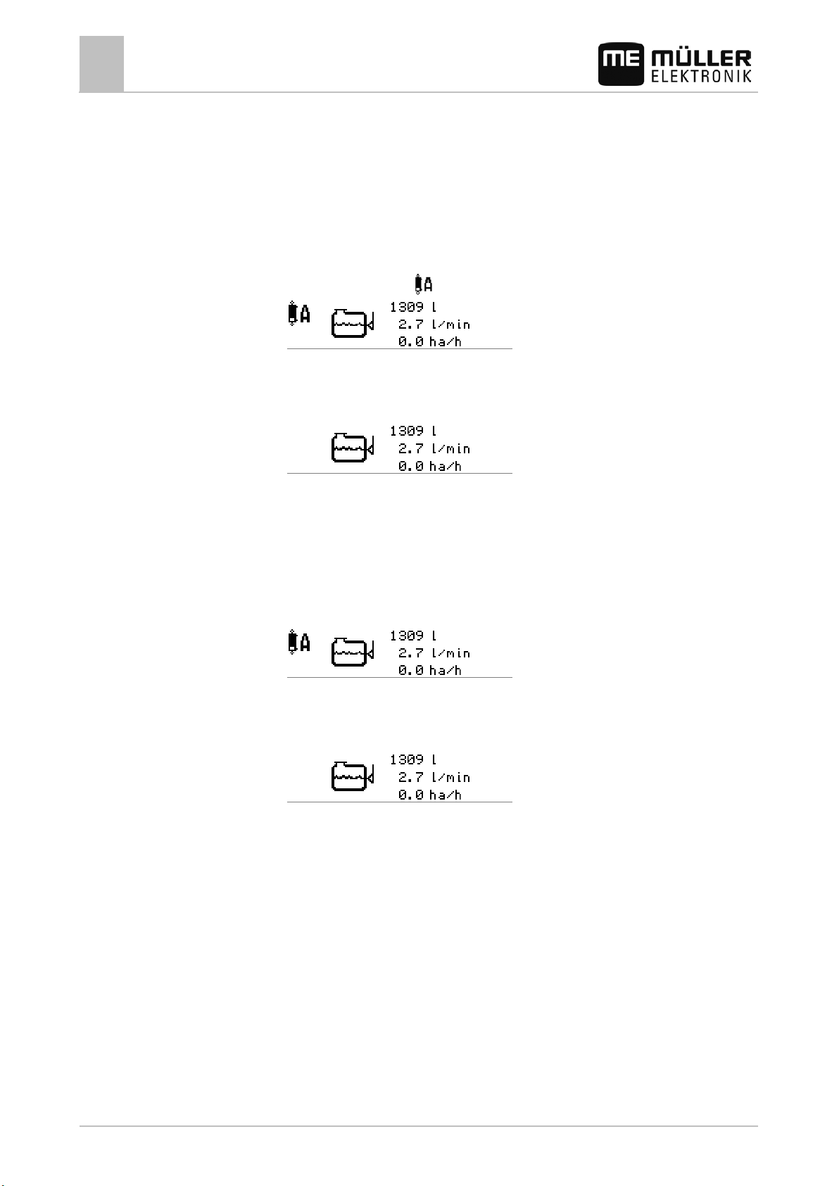
Select the Hydraulic valves function key group on the work screen.
The function keys for working with the hydraulic valves can be configured as follows:
▪ as switches
▪ as keys
30283305-02-EN V5.20150204 53
Page 54
7.8.1
valve
7.8.2
valve
valve
Applying the device in the field
7
Working with hydraulic valves
These are configured in a password-protected area and this can only be done by a service
technician.
Controlling hydraulic valves configured as keys
Hydraulic valves which have been configured as keys are only activated when the function key is
actuated.
Activating the hydraulic
valve
Deactivating the hydraulic
Activating the hydraulic
1. Press and hold the function key for the desired valve.
⇨ The hydraulic valve icon
appears on the work screen.
⇨ The hydraulic valve is activated for as long as the function key remains pressed.
1. Release the function key
⇨ The hydraulic valve icon is hidden on the work screen.
⇨ The hydraulic valve is deactivated.
Controlling hydraulic valves configured as switches
Hydraulic valves which are configured as switches remain active until they are switched off.
1. Press the function key of the desired valve.
⇨ The hydraulic valve icon appears on the work screen.
Deactivating the hydraulic
⇨ The hydraulic valve is activated.
1. Press the function key
⇨ The hydraulic valve icon is hidden on the work screen.
⇨ The hydraulic valve is deactivated.
54 30283305-02-EN V5.20150204
Page 55
8
8.1
8.2
Procedure
8.3
Maintenance and servicing
Maintenance and servicing
Checking the software version
8
Procedure
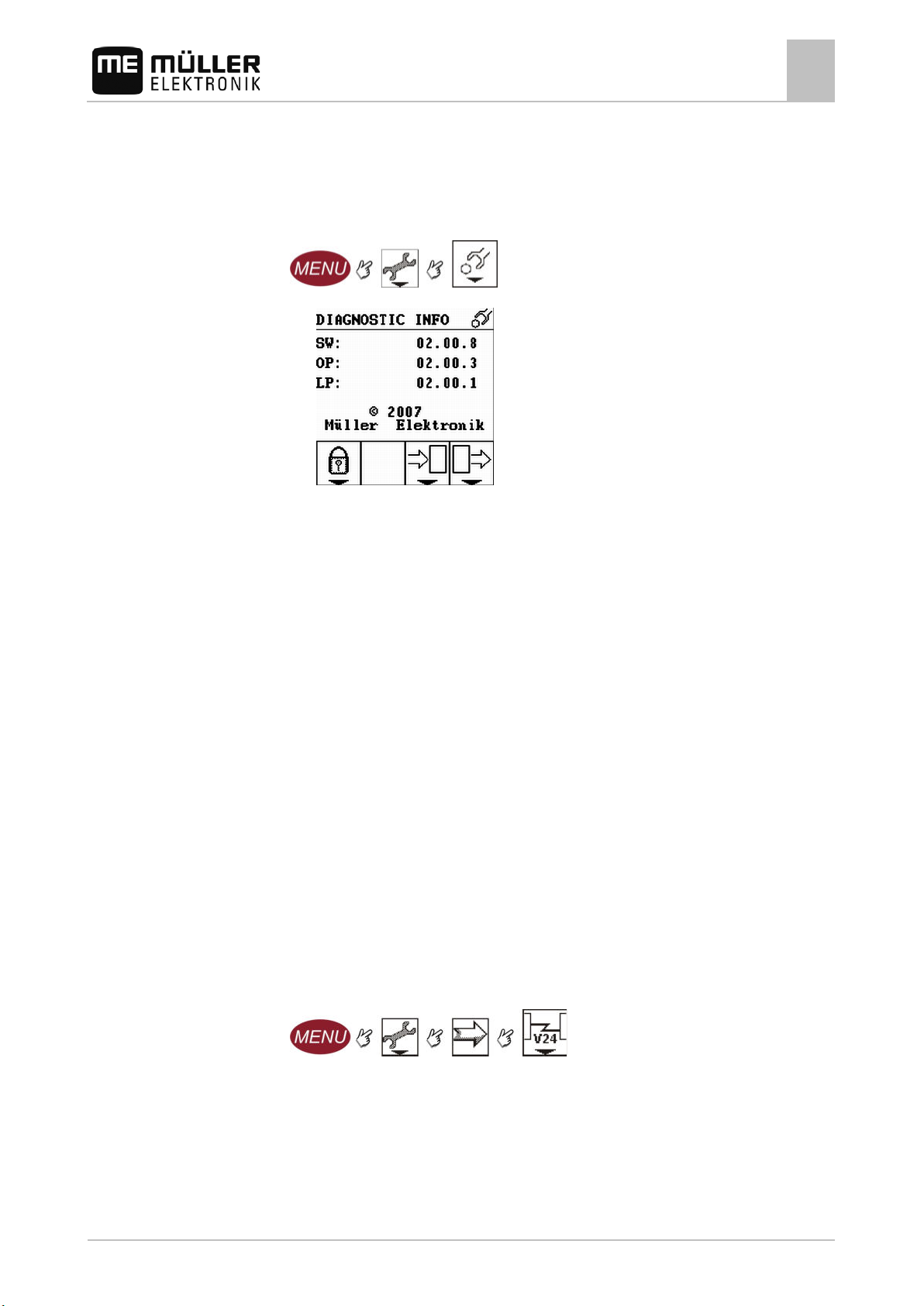
Checking the software version
1. Change to Diagnostic Info screen
⇨ The following screen will appear:
⇨ The following information may appear on the screen:
▪ SW: Software version
▪ OP: "Object Pools" version (icons and graphics)
▪ LP: "Language Pools" version (texts in all languages)
V24 interface
The V24 interface serve to establish the communication between Spraylight and a connected device.
One of the following parameters can be activated on the V24 screen:
▪ SW update: Setting for software updates with the DataBox 2
▪ Hardcopy: here, Müller-Elektronik can load data from Spraylight.
▪ LH5000: The set value is accepted by the LH5000 and the currently applied amount is restored.
▪ ASD: If this parameter is activated, Spraylight can communicate with an ME terminal through the
serial interface. You can find more information on this in the description of the serial interface in
the terminal operating instructions. In this way, the following functions are possible:
– Section control via SECTION-Control
– Target rate import from a prescription map
▪ ASD SC: If this parameter is activated, Spraylight can communicate with an ME terminal through
the serial interface. In this way, the following functions are possible:
– Section control via SECTION-Control
1. Switch to V24 screen:
2. Activate the desired parameters.
Activating simulated speed function
The simulated speed function is only used by the Spraylight during tests. It simulates the movement
of the machine when the machine is at a standstill.
30283305-02-EN V5.20150204 55
Page 56
Procedure
8.4
Procedure
Maintenance and servicing
8
Displaying sensor status
By activating simulated speed, it is possible for customer service employees to check the correct
function of a sensor.
By default the value is set to 0 km/h and the function is switched off.
After restarting the computer, the simulation is always deactivated.
The most recently set value is saved and used during the next activation.
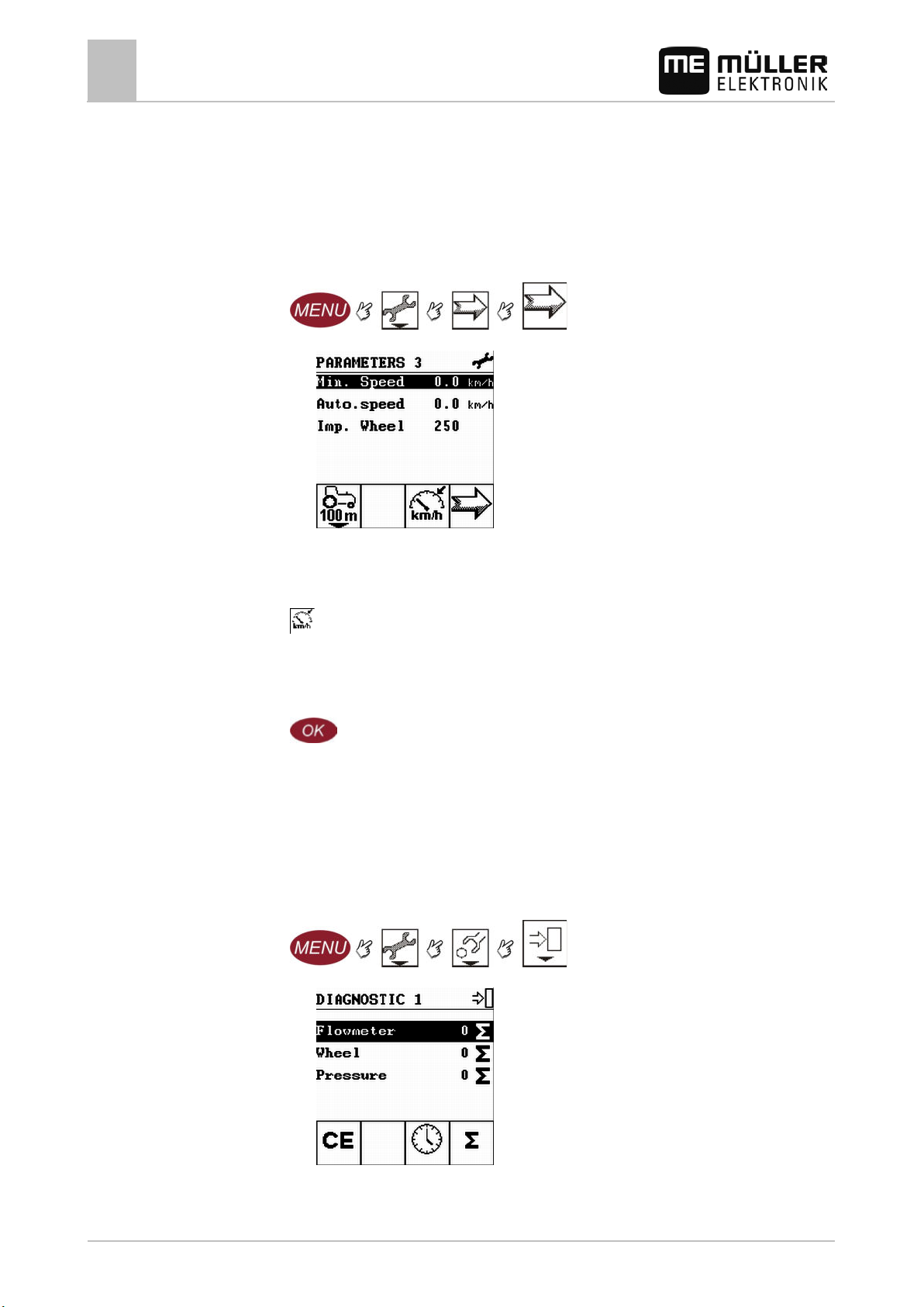
1. Switch to the Parameters 3 screen:
⇨ The following screen appears:
2. Check whether the Sim.speed. line is present:
YES – simulated speed is activated.
NO – simulated speed is deactivated.
3.
- Activate screen to input simulated speed data.
⇨ The data input screen appears.
4. Input the simulated speed.
You can input any value, up to 99.9 km/h.
5.
- Confirm.
⇨ The new Sim.speed parameter appears in the Parameters 3 screen.
Displaying sensor status
The screens in this area contain information that is mainly of interest for customer service.
ou can read out the condition of sensors in the Diagnosis 1 screen.
1. Switch to the DIAGNOSTIC 1 screen:
⇨ The following screen appears:
In each of the lines of the screen you will find:
- The name of the sensor
56 30283305-02-EN V5.20150204
Page 57
Parameter
Value
Operating temperature
-20 – +70 °C
Storage temperature
-30 – +80 °C
Weight
1 kg
Dimensions (W x H x D)
170 x 165 x 90 mm
suppression level 4
Power input
5 Watt
Controls
8.5
8.6
8.7
Maintenance and servicing
Maintaining and cleaning device
8
- Current value of the sensor/counter
- Unit in which the sensor value is displayed
⇨ Depending on the system's configuration, different sensors may be displayed here:
Flowmeter – Flow meter
Wheel – Wheel sensor
Pressure – Pressure sensor
Tank – Tank-Control
2. You can decide for yourself what unit to use to display the sensor value by pressing the function
keys.
3. You can also reset the sensor value to 0.
Display the sensor value in pulses per minute
Display the sensor value as the total no. of pulses
Reset the sensor value to 0
Maintaining and cleaning device
▪ Only clean Spraylight with a soft damp cloth wet with clear water or glass cleaner.
Disposing of the unit
When it has reached the end of its service life, please dispose of this product as
electronic scrap in accordance with applicable EU legislation.
Technical specifications
Operating voltage 10 - 30 V
Protection class IP 54 in accordance with DIN 40050/15
EMC In accordance with ISO 14982 / PREN 55025 Interference
ESD protection In accordance with ISO 10605 Level 3
30283305-02-EN V5.20150204 57
Page 58
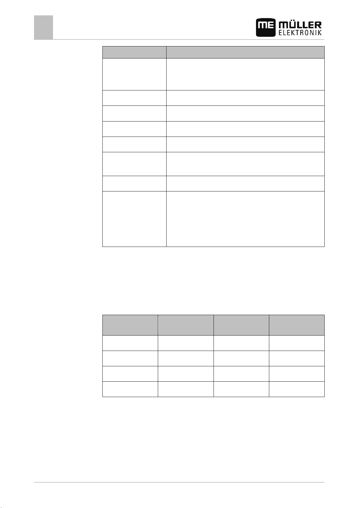
Parameter
Value
compensation
Processor
60 MHz ARM7 LPC2214 with internal 256k flash disk and 16k RAM
Boot USB
2MB
an external power supply.
1
Wheel sensor
5
Working position
3
0 VE
7
RS232 RxD
4
PTO
8
RS232 TxD
8.8
8.9
Maintenance and servicing
8
Plug assignment - 8-pole flange socket
Display 160 x 160 pixel LCD display, transflective with white LED backlighting;
software-controlled contrast, brightness and temperature
RAM 1 MB
Serial FRAM 8kB
Real Time Clock Buffered by capacitor, keeps the time for more than 2 weeks without
Keyboard 14 keys plus On/off key, all backlit
Outputs 4 high-side switches with current measurement, 3.5A.
8 full bridges with current measurement max. 1.5 A per bridge and 1x
5A
Due to input protection, overall power consumption should not exceed
10A.
Plug assignment - 8-pole flange socket
These abbreviations are used in the following table:
▪ VE – Electronics voltage
▪ VL – Power voltage
8-pole flange socket
Pin no.
Signal 8-pole flange socket
Pin no.
Signal
2 +12 VE 6 Radar
Plug assignment - 39-pole clip connector
These abbreviations are used in the following table:
▪ VE – Electronics voltage
▪ VL – Power voltage
▪ A – Series A
▪ B – Series B
58 30283305-02-EN V5.20150204
Page 59
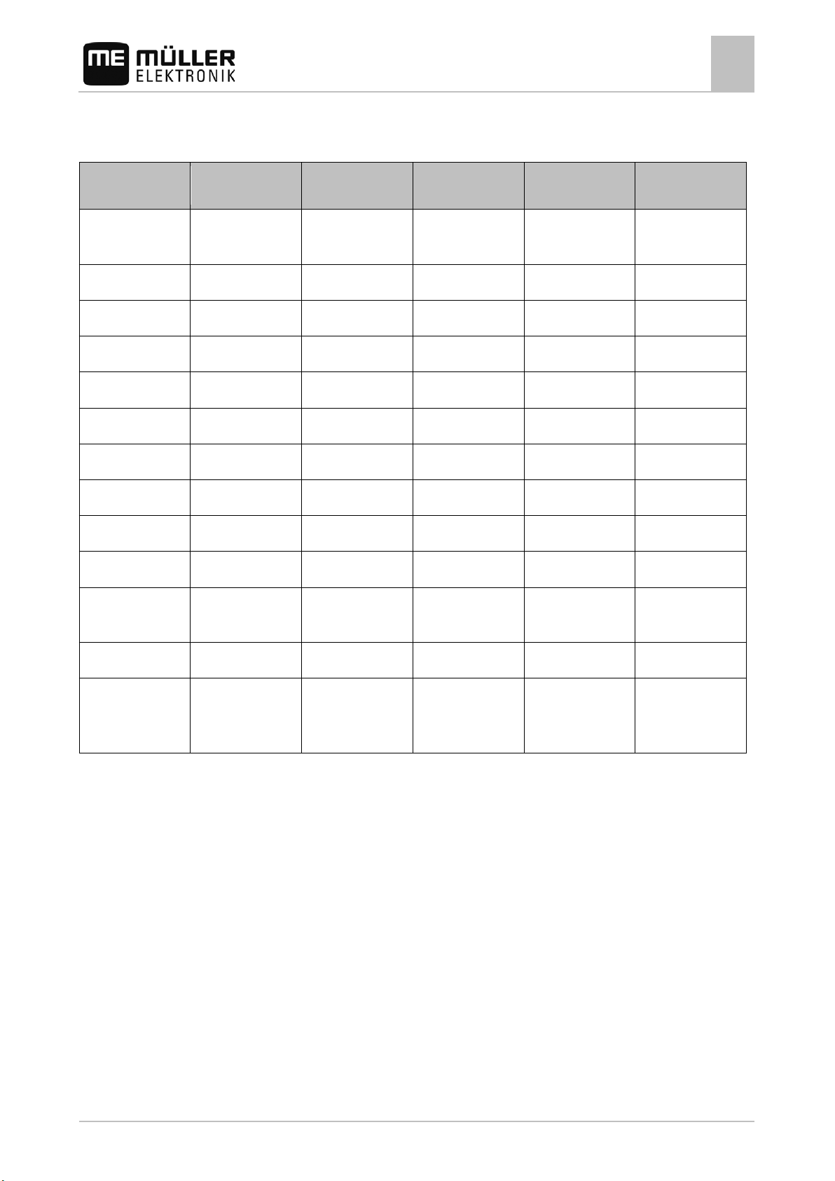
Pin no.:
Pin no.:
Pin no.:
PWM fan –Caffini
A3
Bypass
B3
Section-6 B
C3
Hydraulic C
A4
Bypass
B4
Section-7 A
C4
Hydraulic D
A6
Section-1 B
B6
12 VL
C6
free
A8
Section-2 B
B8
12 VL
C8
Flow meter
A9
Section-3 A
B9
12 VL
C9
0 VE
(analog)
Maintenance and servicing
Plug assignment - 39-pole clip connector
8
▪ C – Series C
39-pole connector
Signal 39-pole connector
Signal 39-pole connector
Signal
A1 Regulation B1 Section-5 B C1 Hydraulic A or
A2 Regulation B2 Section-6 A C2 Hydraulic B
A5 Section-1 A B5 Section-7 B C5 Circulation valve
A7 Section-2 A B7 12 VL C7 12 VE
A10 Section-3 B B10 0 VL C10 Wheel sensor
A11 Section-4 A B11 0 VL C11 Pressure sensor
A12 Section-4 B B12 0 VL C12 Tank Control
A13 Section-5 A B13 0 VL C13 Pressure sensor
(digital) or PWM fan
sensor – Caffini
Ports C4 and C5 are bridged.
30283305-02-EN V5.20150204 59
Page 60
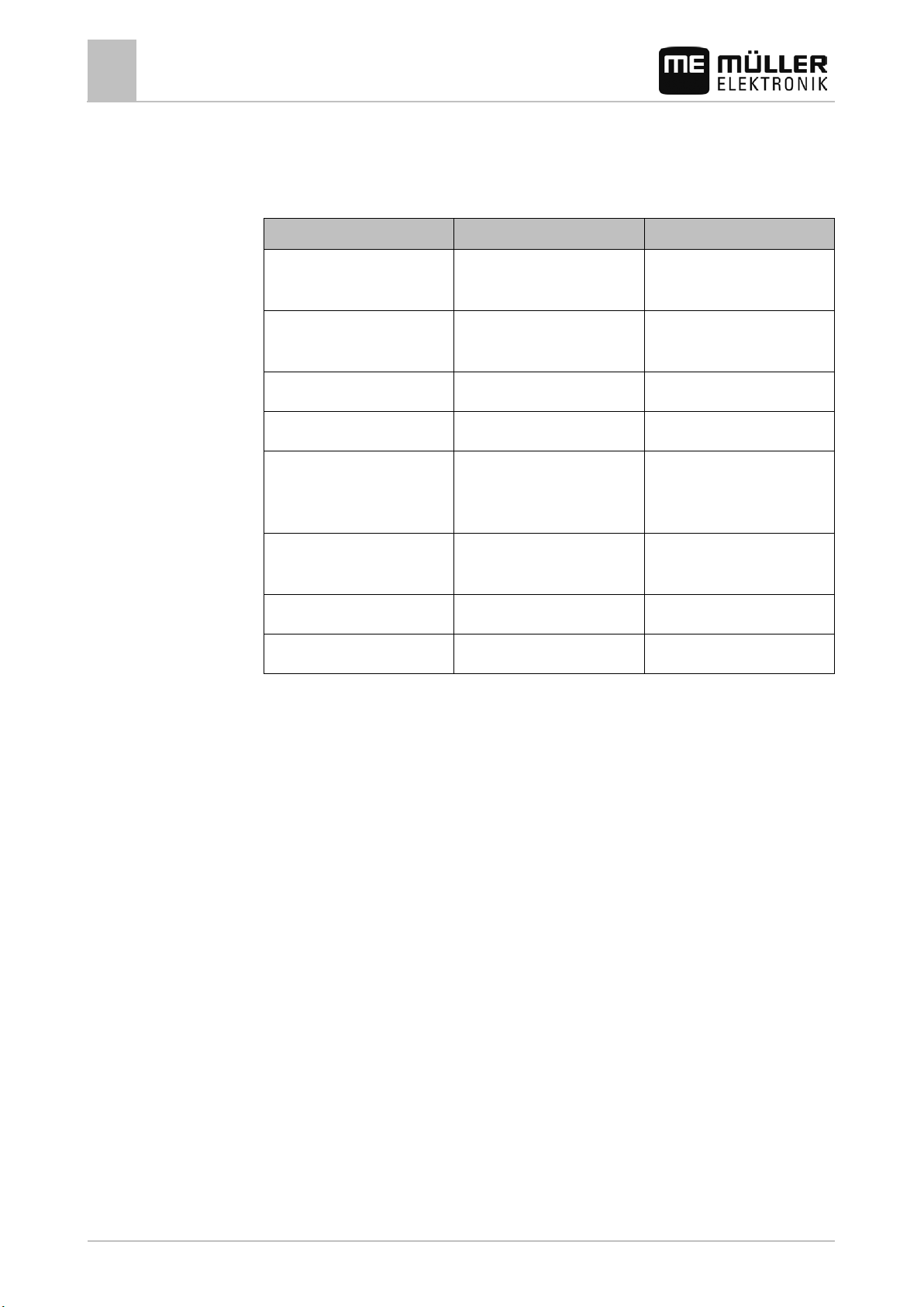
Fault description
Possible cause
Help
terminals.
No speed is displayed
Missing pulse/100m input
Input number of pulses/100m
computer.
5-10 mm.
Sensor is faulty, replace
No surface is shown
Working width entry is missing
Input working width
9
9.1
Troubleshooting
9
Table of potential faults
Troubleshooting
Table of potential faults
The device does not switch on Incorrect power supply polarity Check the battery connector
cable.
Interruption in the power supply. Check the battery and fuse
Total failure Send in the device
The wheel sensor does not
send any pulses to the
The red site of the magnet must
Set the distance between the
wheel sensor and the magnet at
face the sensor.
60 30283305-02-EN V5.20150204
 Loading...