

Page 1
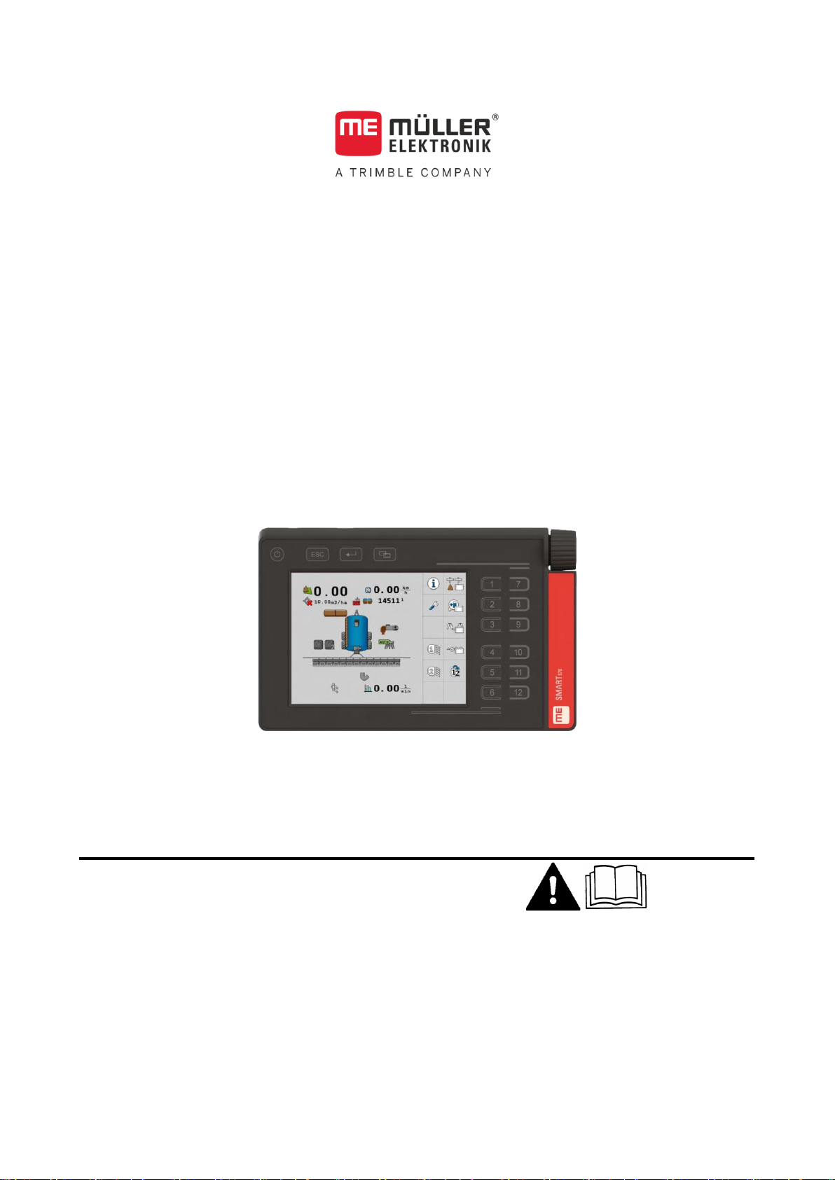
Installation and operating instructions
SMART570
Version: V8.20220707
30322507-02-EN
Read and follow these instructions. Keep these instructions in a
safe place for later reference. Please note that there might be a
more recent version of these instructions on the homepage.
Page 2

Document
Copyright ©
Company details
Installation and operating instructions
Product: SMART570
Document number: 30322507-02-EN
As of software version: 00.03.04.00
Original instructions
Original language: German
Müller-Elektronik GmbH
Franz-Kleine-Straße 18
33154 Salzkotten
Germany
Phone: ++49 (0) 5258 / 9834 - 0
Fax: ++49 (0) 5258 / 9834 - 90
Email: [email protected]
Homepage: http://www.mueller-elektronik.de
Page 3
Table of contents
30322507-02-EN
V8.20220707
3
1
For your safety
5
1.1
Basic safety instructions
5
1.2
Intended use
5
1.3
Layout and meaning of warnings
5
2
About these Operating Instructions
7
2.1
Target group of these Operating Instructions
7
2.2
Directional information in these instructions
7
2.3
Layout of operating instructions
7
2.4
Layout of references
7
3
Product description
8
3.1
Scope of delivery
8
3.2
Front
8
3.3
Rear
9
3.4
Rating plates
9
3.5
EU declaration of conformity
10
4
Installation
11
4.1
Mounting the terminal in the vehicle cab
11
4.2
Connecting the terminal to the ISOBUS
12
4.3
Connecting sensors to the terminal
12
5
Basic control principles
13
5.1
Initial start-up
13
5.2
Operating the terminal
13
5.2.1
Operating the terminal using the buttons and rotary encoder
13
5.2.2
Operating the terminal using the screen
14
5.3
Changing parameters
15
5.3.1
Changing parameters using the screen
15
5.3.2
Changing parameters with the rotary encoder
15
5.4
Using the joystick
16
6
Configuration of the terminal
17
6.1
App selection
17
6.2
Brightness mode
17
6.3
System settings
18
6.3.1
Formats and units
19
6.3.2
Terminal
20
6.3.3
Vehicle
20
Calibrating the speed sensor
21
Counters
22
6.4
Button assignment for AUX operating devices
23
Table of contents
Page 4

Table of contents
4
V8.20220707
30322507-02-EN
6.5
Diagnostics
24
6.5.1
Diagnostic of connected devices
25
6.5.2
Deleting the object pool
26
6.6
Information
26
7
Technical specifications
28
7.1
Technical specifications of the terminal
28
7.2
Pin assignment
28
7.2.1
9-pin CPC connector
28
7.2.2
5-pin M12 connector
29
8
Appendix
30
8.1
Updating the terminal
30
Page 5
For your safety
Basic safety instructions
1
30322507-02-EN
V8.20220707
5
WARNING
This signal word identifies medium-risk hazards, which could potentially cause death or serious
physical injury, if not avoided.
CAUTION
This signal word identifies hazards that could potentially cause minor or moderate physical injury or
damage to property, if not avoided.
1
1.1
1.2
1.3
For your safety
Basic safety instructions
Please read the following safety instructions carefully before using the product for the first time.
▪ Before maintenance or repair to the tractor, always disconnect the connection between the
tractor and the terminal.
▪ Before charging the tractor battery, always disconnect the connection between the tractor and
the terminal.
▪ Before welding on the tractor or implement, always disconnect the power supply to the terminal.
▪ Do not make any unauthorized modifications to the product. Unauthorized modifications or use
may impair safety and reduce the service life or operability of the unit. Modifications are
considered unauthorized if they are not described in the product documentation.
▪ Follow all recognised safety, industrial and medical rules as well as all road traffic laws.
▪ Do not operate the terminal while driving in road traffic. Come to a standstill in order to use the
unit.
▪ The product does not include any user-serviceable parts. Do not open the casing. If the casing is
opened, its imperviousness can be changed.
▪ Read the operating instructions to the agricultural device which you want to control by using the
product.
Intended use
The terminal is used to operate agricultural machinery equipped with ISOBUS job computers.
Intended use also includes compliance with the conditions for operation and repairs prescribed by the
manufacturer.
The manufacturer cannot be held liable for any personal injury or property damage resulting from
non-compliance. All risk arising from improper use lies with the user.
All applicable accident prevention regulations and all other generally recognized safety, industrial,
and medical standards as well as all road traffic laws must be observed. Any unauthorized
modifications made to the equipment will void the manufacturer's warranty.
Layout and meaning of warnings
All safety instructions found in these Operating Instructions are composed in accordance with the
following pattern:
Page 6
1
For your safety
Layout and meaning of warnings
6
V8.20220707
30322507-02-EN
NOTICE
This signal word identifies hazards that could potentially cause damage to property, if not avoided.
Example
There are some actions that need to be performed in several steps. If there is a risk involved in
carrying out any of these steps, a safety warning appears in the instructions themselves.
Safety instructions always directly precede the step involving risk and can be identified by their bold
font type and a signal word.
1. NOTICE! This is a notice. It warns that there is a risk involved in the next step.
2. Step involving risk.
Page 7
About these Operating Instructions
Target group of these Operating Instructions
2
30322507-02-EN
V8.20220707
7
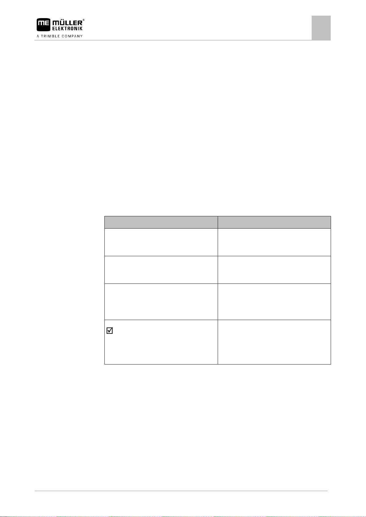
Type of depiction
Meaning
1.
2.
Actions that must be performed in succession.
⇨
Result of the action.
This will happen when you perform an action.
⇨
Result of an operating instruction.
This will happen when you have completed all
steps.
Requirements.
In the event that any requirements have been
specified, these must be met before an action
can be performed.
2
2.1
2.2
2.3
2.4
About these Operating Instructions
Target group of these Operating Instructions
These Operating Instructions are intended for personnel entrusted with installing and operating the
terminal.
Directional information in these instructions
All directional information in these instructions, such as “left”, “right”, “forward”, “back”, is relative to
the movement direction of the vehicle.
Layout of operating instructions
The operating instructions explain step by step how you can perform certain operations with the
product.
We use the following symbols throughout these Operating Instructions to identify different operating
instructions:
Layout of references
If any references are given in these Operating Instructions, they appear as:
Example of a reference: [➙ 7]
References can be identified by their square brackets and an arrow. The number following the arrow
shows you the page on which the section where you can find further information starts.
Page 8
3
Product description
Scope of delivery
8
V8.20220707
30322507-02-EN
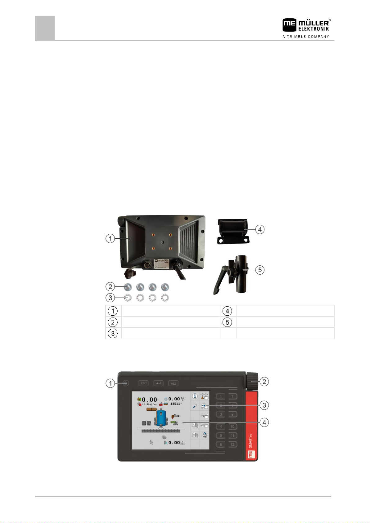
Terminal
Terminal plate
Bolts Pipe bracket
Washer
3
3.1
3.2
Product description
The SMART570 operating and display device complies with ISOBUS standard ISO 11783 and can be
used as an Universal Terminal (UT) on all ISOBUS machines, regardless of manufacturer. The
integrated ISOBUS functions are AEF certified.
The colour display of the SMART570 has a resolution of 640 x 480 pixels. The SMART570 offers a
capacitive touch screen, a membrane keyboard and a rotary encoder for optimum operation of the
connected implement. A total of 12 softkeys can be operated both via the membrane keyboard and
via touch display. The latter supports the driver with text input by providing a complete keyboard on
the screen. The rotary encoder enables rapid value changes for numerical inputs.
The SMART570 supports AUX-N functionality according to ISO 11783. The functions of connected
AUX-N devices can be assigned to the keys of AUX-N operating device in a convenient editor.
The mini tractor functionality completes the SMART570's range of functions. Speed and work position
signals are evaluated and displayed in the form of a small dashboard.
The SMART570 is connected to the CAN bus via a cabled CPC connector.
Scope of delivery
Front
Front view
Page 9
Product description
Rear
3
30322507-02-EN
V8.20220707
9
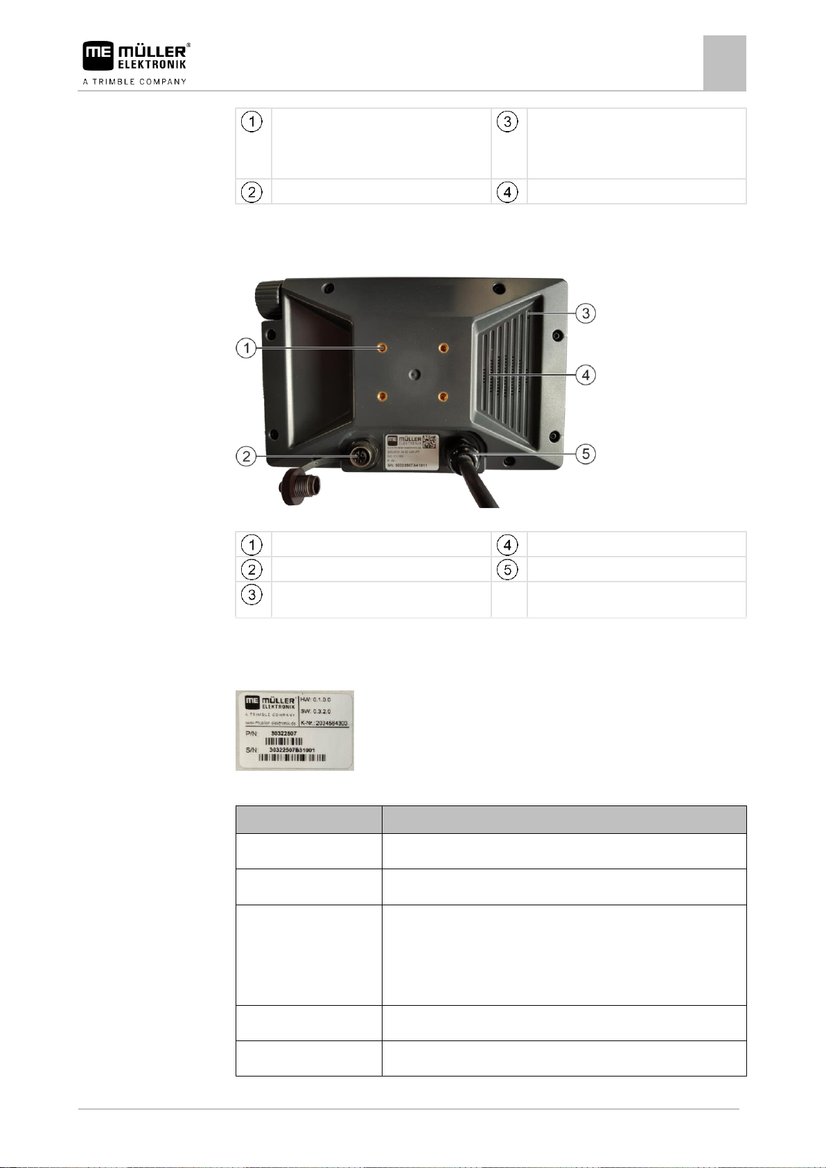
Buttons on the casing
Function icons
Depiction of an available function. The
functions are executed when you press on the
respective function button.
Rotary encoder
Screen content
Thread for the bracket screws
Speaker
Connection to the 7-pin signal socket
Connection to ISOBUS
Pressure compensation membrane (must
never be covered)
Abbreviation
Meaning
HW
Hardware version
SW
Software version upon delivery
K-Nr
Customer number
If the product was manufactured for an agricultural machinery
manufacturer, the agricultural machinery manufacturer's item number
will be shown here.
P/N
Müller-Elektronik item number
S/N
Serial number
3.3
3.4
Rear
Rear view
Rating plates
Abbreviations on the rating plate
Page 10
3
Product description
EU declaration of conformity
10
V8.20220707
30322507-02-EN
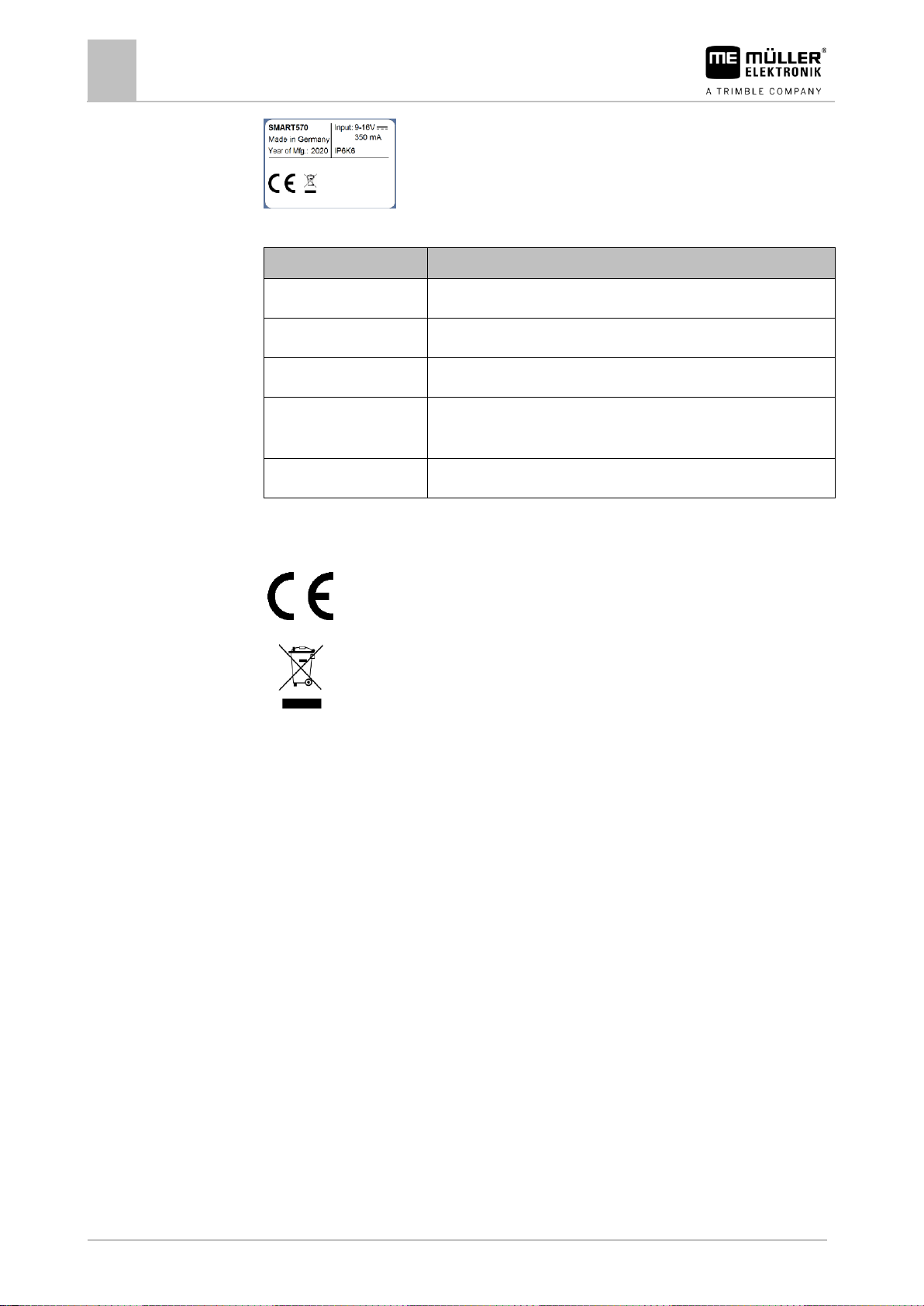
Entry
Meaning
SMART570
Name of the product
Made in Germany
Country of manufacture
Year of Mfg.
Year of manufacturing
Input
Operating voltage 9-16 V, ⎓ = DC voltage, current consumption
350 mA
IP6K6
Protection class according to ISO 20653
The concept and design of the product as well as the model we put on the market
comply with the applicable legal provisions of the EU.
When it has reached the end of its service life, please dispose of this product as
electronic scrap in accordance with all applicable waste management laws.
Harmonised standards applied:
EN ISO 14982:2009
(EMC Directive 2014/30/EU)
3.5
Information on the rating plate
Symbols on the rating plate
EU declaration of conformity
Herewith we declare that the design and construction of this product and its identical variants, as well
as the form brought onto the market by us, is in accordance with the relevant safety and health
requirements of the EU Directive of Electromagnetic Compatibility 2014/30/EU. If alterations are
made to the product without prior consultations with us, this declaration becomes invalid.
SMART570
Page 11
Installation
Mounting the terminal in the vehicle cab
4
30322507-02-EN
V8.20220707
11
4
4.1
Procedure
Installation
Mounting the terminal in the vehicle cab
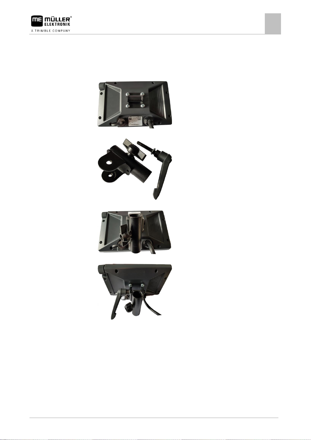
1. Screw the terminal plate onto the rear of the terminal: Always use all four screws supplied.
2. Unscrew the long bolt out of the pipe bracket:
3. Attach the two bracket components together:
4. Insert the long bolt through the assembled bracket:
5. Screw in the long bolt until the terminal is firmly attached.
⇨ You can now attach the terminal with the bracket on a round pipe (e.g. on the ME mounting
bracket).
Page 12

4
Installation
Connecting the terminal to the ISOBUS
12
V8.20220707
30322507-02-EN
4.2
Procedure
4.3
Connecting the terminal to the ISOBUS
When it is connected to the ISOBUS, the terminal is supplied with voltage and communication is
possible with other ISOBUS components.
1. Connect the connector cable to the basic vehicle harness or the ISOBUS In-Cab-Connector.
2. Screw in the connector tightly.
⇨ You have connected the terminal to the ISOBUS.
Connecting sensors to the terminal
The terminal can receive signals from the following sensors:
▪ Work position sensor
Purpose:
– Display of the work position on the start screen.
– Transmission of the signal received through the signal socket to the ISOBUS.
Possible signal sources:
– 7-pin signal socket on the sensor connection of the terminal.
– An ISOBUS job computer.
▪ Speed sensor
Purpose:
– Display of the speed on the start screen.
– Transmission of the signal received through the signal socket to the ISOBUS.
Possible signal sources:
– 7-pin signal socket on the sensor connection of the terminal.
Page 13
Basic control principles
Initial start-up
5
30322507-02-EN
V8.20220707
13
Illustration
Action
Function
/
Turning the rotary
encoder
Moves the cursor up or down.
Changes the value of a parameter.
5
5.1
Procedure
5.2
5.2.1
Rotary encoder
Basic control principles
Initial start-up
For the initial start-up, you must switch on and configure the terminal.
The terminal is installed and connected to the ISOBUS.
1. - Start the terminal.
⇨ The terminal will now be started.
⇨ Each time the terminal is started, it checks whether unknown job computers are connected
to the ISOBUS. If yes, the terminal then copies the information from the job computer. This
can take a little while.
⇨ If a joystick or other operating device is detected, you will be requested to confirm the button
assignment [➙ 16].
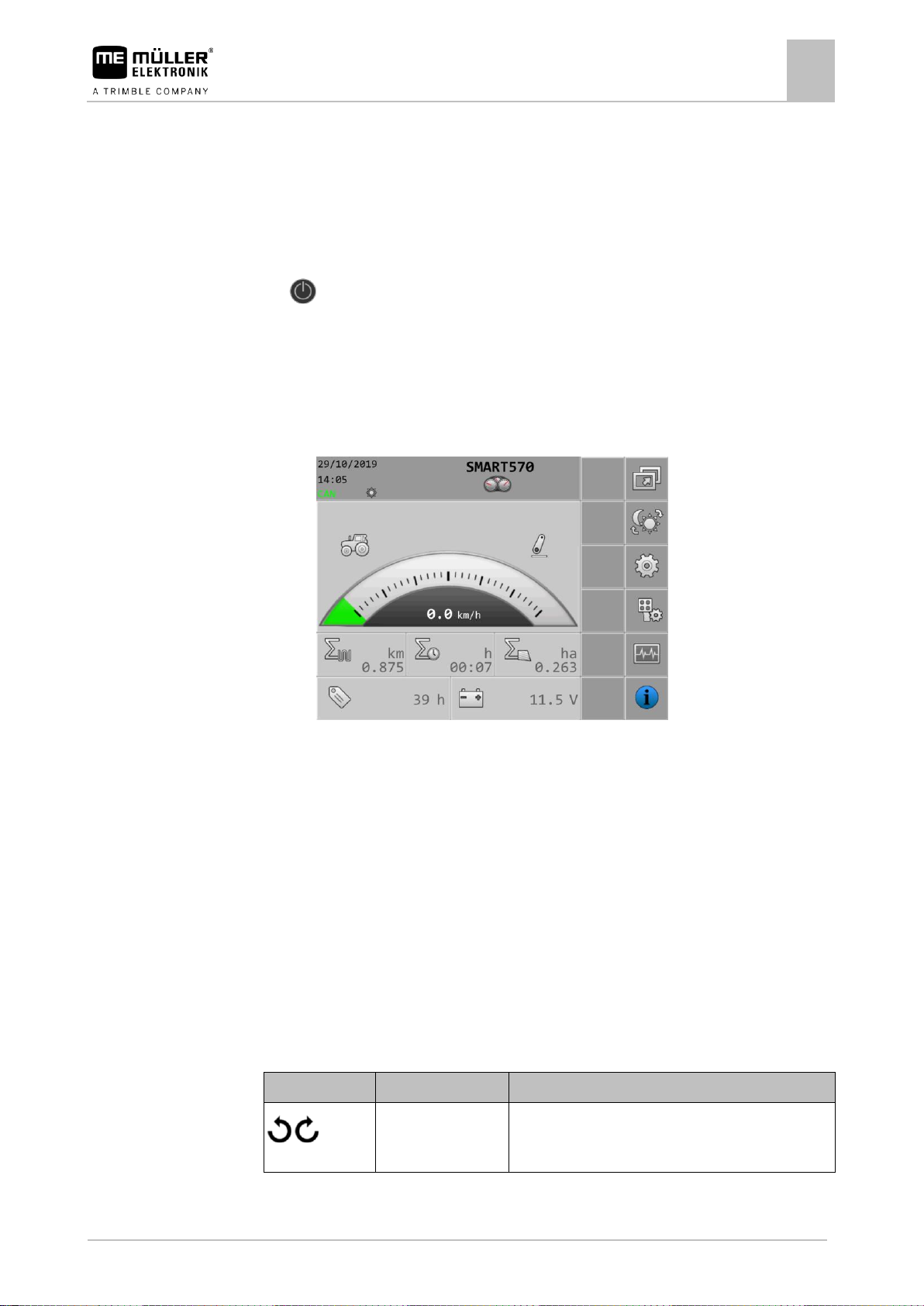
⇨ The following screen appears:
⇨ You can change the system settings through this screen.
2. Configure the system settings [➙ 18].
3. Configure the speed sensor [➙ 20].
⇨ You have configured the terminal.
Operating the terminal
The terminal can be operated either using the buttons on the casing and the rotary encoder or directly
with the touch function of the screen.
All functions of the terminal can be executed using both operating methods.
Operating the terminal using the buttons and rotary encoder
The following functions can be executed with the rotary encoder:
Page 14
5
Basic control principles
Operating the terminal
14
V8.20220707
30322507-02-EN
Illustration
Action
Function
Pushing the rotary
encoder
Clicks on the marked line.
Activates the marked parameter.
Confirms the input.
Button
Designation
Function
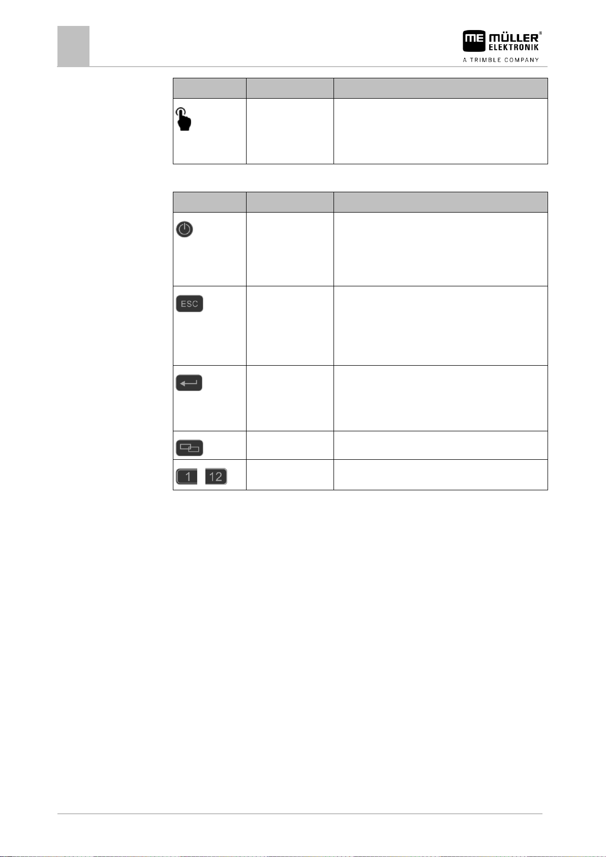
ON/OFF button
Pressing the button for 1 second: Switches the terminal
on.
Pressing the button for 2 seconds: Switches the terminal
off.
Cancel button
Sends a cancel signal to the job computer.
Cancels the input of a value. The input box is exited and
the previous valid value is restored.
Acknowledges alarms.
Enter button
Opens an input box.
Confirms the input.
Acknowledges alarms.
Toggle button
Switches to a different app.
…
Function buttons
Performs the respective function shown on the screen.
Buttons
5.2.2
The following functions can be executed with the buttons on the casing:
Operating the terminal using the screen
With the touch function of the screen, you can execute the following actions directly by pressing on
the respective area of the screen:
▪ Executing of functions using the respective function icons.
▪ Selecting parameters.
▪ Changing values for individual parameters.
Page 15
Basic control principles
Changing parameters
5
30322507-02-EN
V8.20220707
15
5.3
5.3.1
Procedure
5.3.2
Procedure
Changing parameters
Changing parameters using the screen
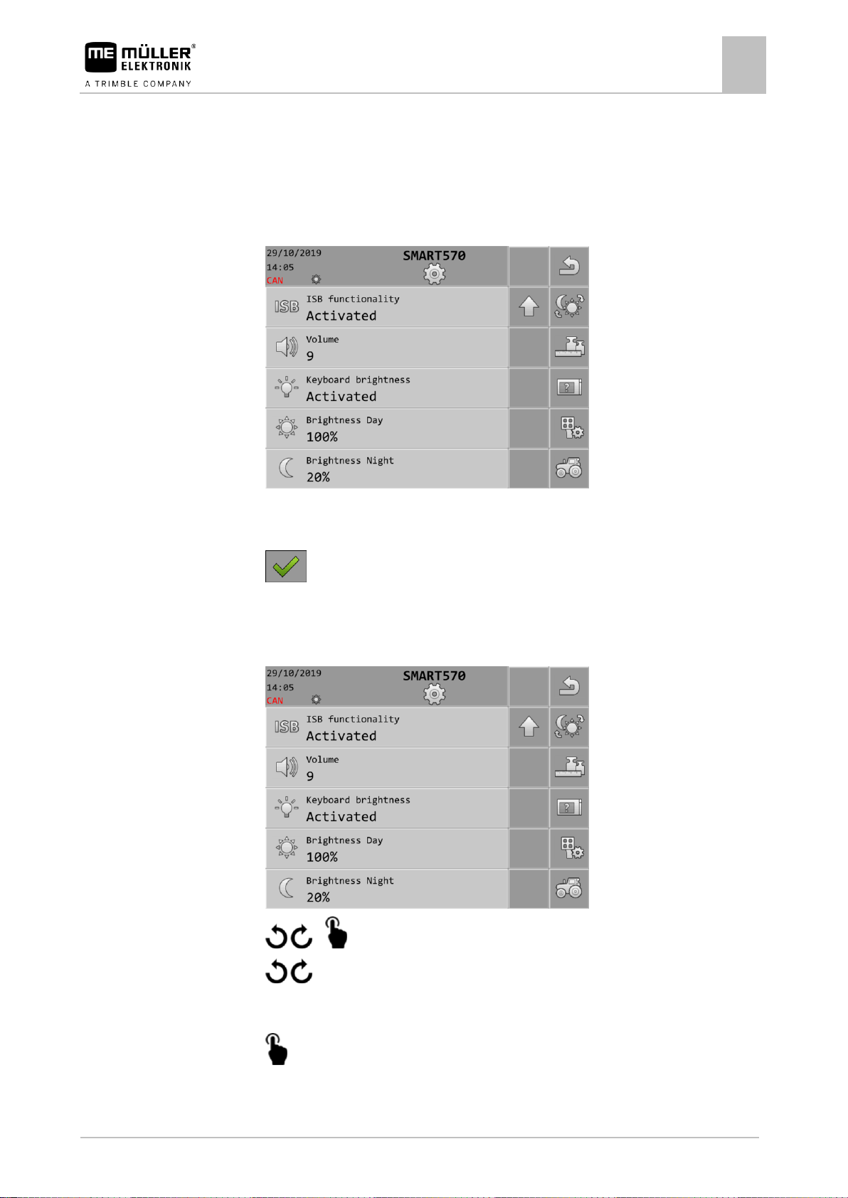
1. Call up a screen with adjustable parameters. For example:
2. Press on the parameter that you want to change.
3. Change the value.
4. - Confirm the input.
Changing parameters with the rotary encoder
1. Call up a screen with adjustable parameters. For example:
2. / > - Select the parameter that you want to change.
3. / - Change the value.
Please note that for text inputs or number inputs with more than 3 digits, the values can only be
changed directly with the touch function of the screen
4. - Confirm the input.
Page 16
5
Basic control principles
Using the joystick
16
V8.20220707
30322507-02-EN
5.4
Procedure
Using the joystick
If an AUX-2 operating device (e.g.: joystick) is detected, an overview of the configured button
assignment is shown every time the terminal is started.
You have started the terminal.
1. The button assignment will be loaded.
2. The following message appears: “Confirm or discard the AUX button assignments in the
following screen."
3. - Confirm.
⇨ A screen with the current button assignment appears.
4. Check whether the displayed button assignment is correct.
5. - Accept the button assignment or discard the button assignment.
Page 17
Configuration of the terminal
App selection
6
30322507-02-EN
V8.20220707
17
Function icon
Meaning
Switches back to the previous screen.
6
Procedure
6.1
Path
Controls
6.2
Path
Configuration of the terminal
From the start screen of the terminal, you can configure different terminal parameters and functions.
The individual parameters can be configured at several points.
If parameters are greyed out, they cannot be changed. They only serve as information.
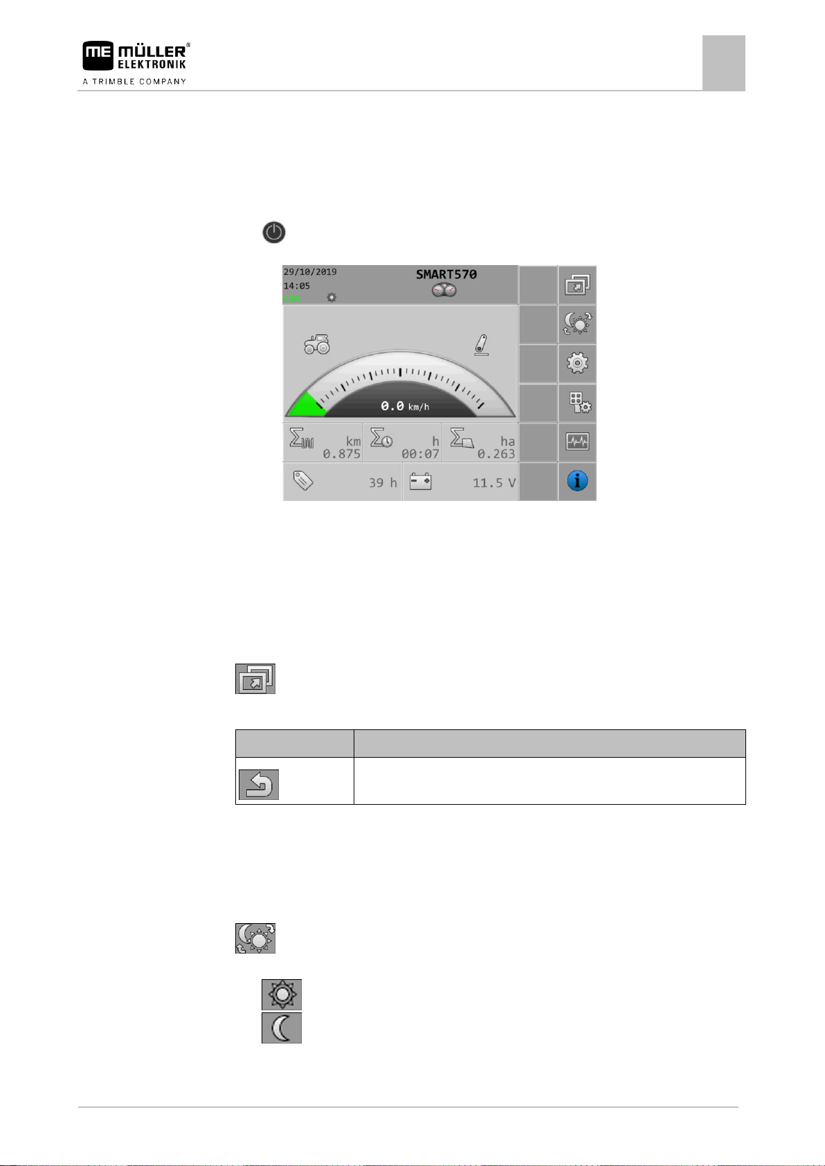
1. - Start the terminal.
⇨ The start screen appears:
2. Configure the desired parameters.
App selection
On this screen, you can switch between different apps, for example, between the terminal and a
connected job computer or joystick.
On the start screen, press:
The following function icons appear on the screen:
Brightness mode
You can change the brightness mode while working.
On the start screen, press:
The mode that is currently activated can be seen by the respective icons on the screen:
▪ - Day mode is activated.
▪ - Night mode is activated.
Page 18
6
Configuration of the terminal
System settings
18
V8.20220707
30322507-02-EN
Function icon
Meaning
Switches back to the previous screen.
Changes the brightness mode.
Switches to the format and unit settings.
Switches to the terminal settings.
Switches to the AUX device settings.
Switches to the vehicle settings.
Scrolls to the previous page of the screen.
Scrolls to the next page of the screen.
Parameter
Meaning
Date
Current date.
Time
Current time.
Time zone
Current time zone.
User language
Operating language for the terminal.
The selection list shows all of the languages that are supported by at least
one connected job computer or the terminal.
If the terminal supports the language selected here, it will be activated in this
language. Otherwise, the terminal will be activated in the language defined
as the “System language”.
System language
Alternative language for the terminal.
ISB functionality
Status of the ISB functionality.
6.3
Path
Controls
Parameter
System settings
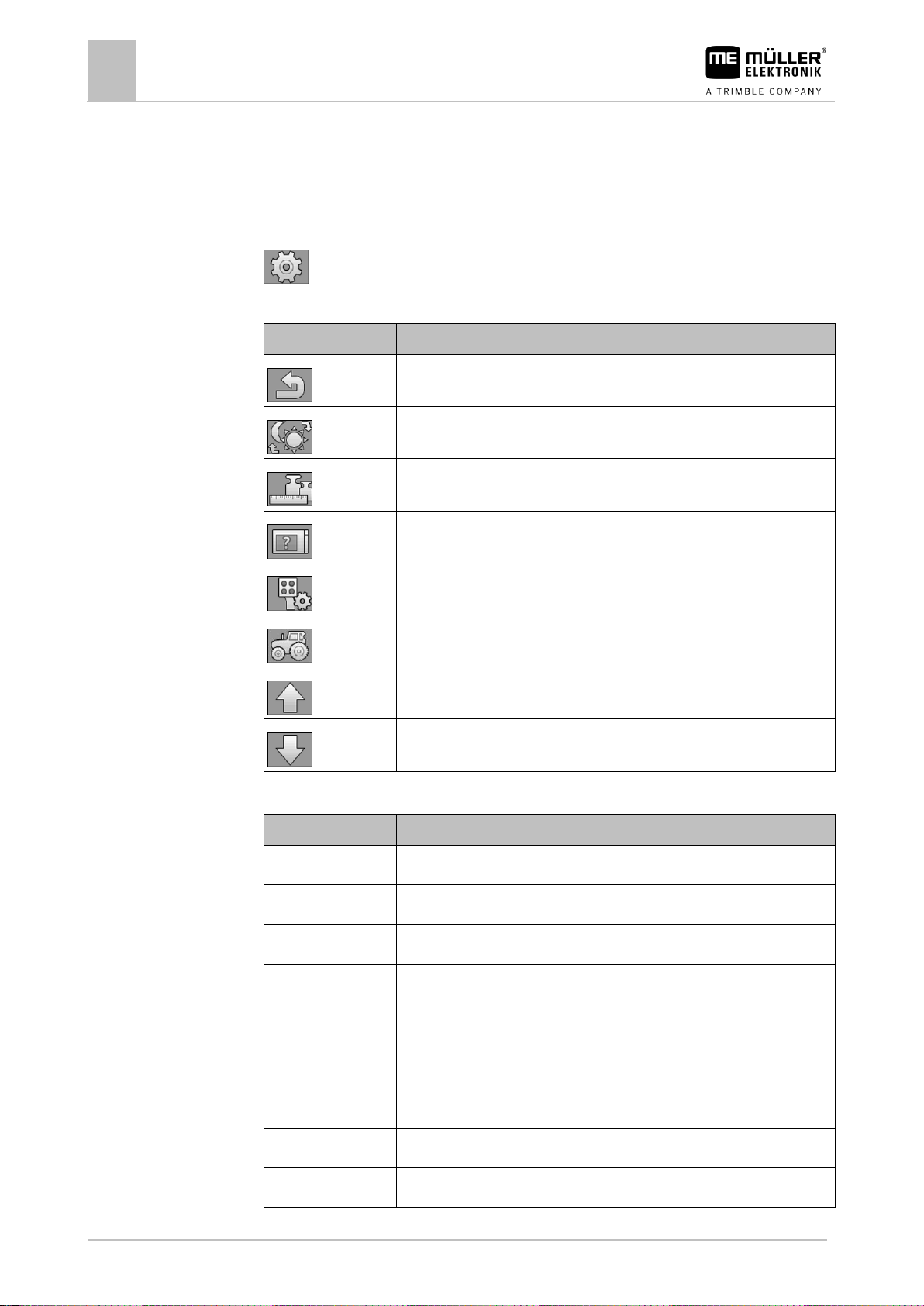
You can change the different basic system settings on this screen.
On the start screen, press:
The following function icons appear on the screen:
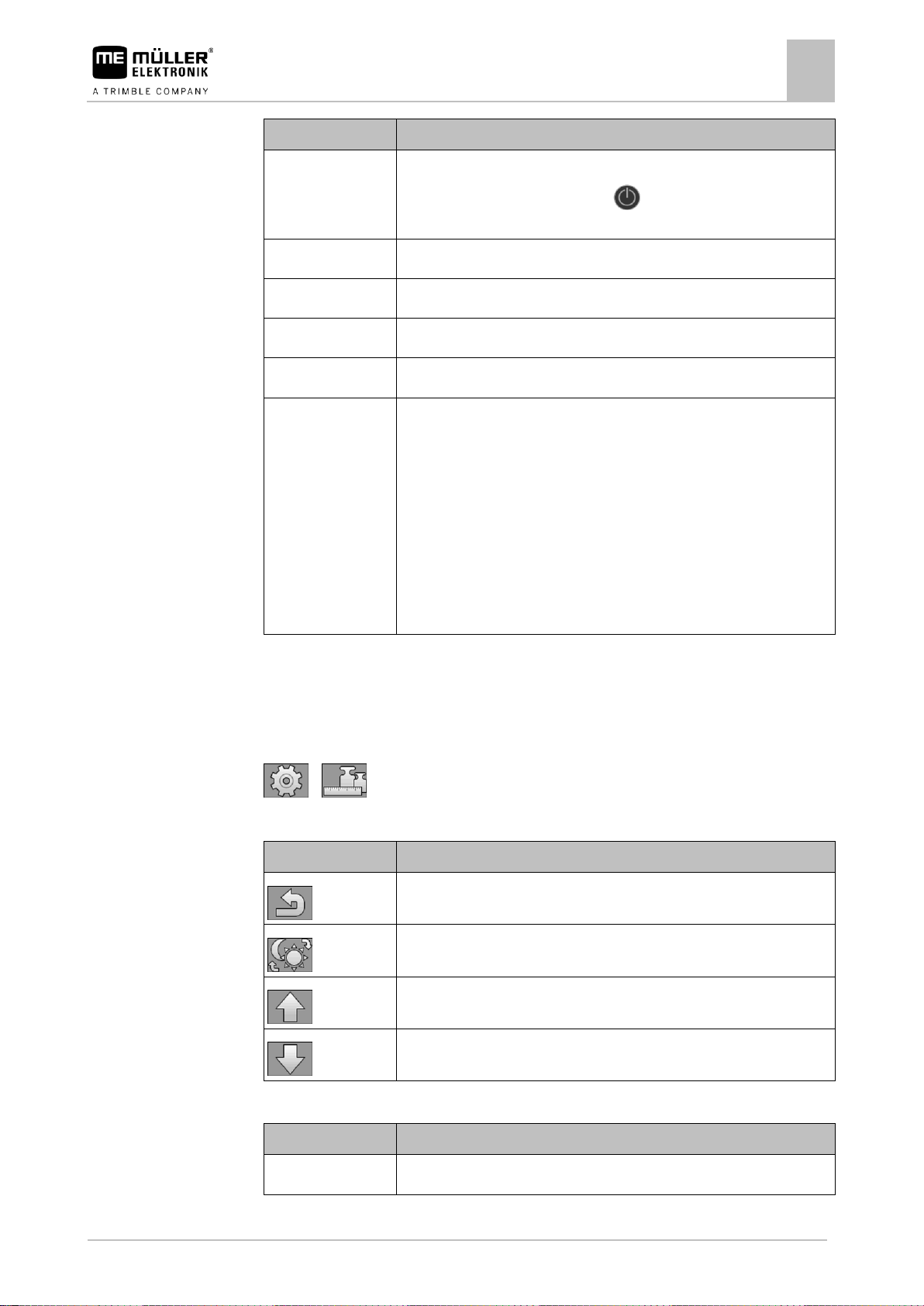
The following parameters can be configured on this screen:
Page 19
Configuration of the terminal
System settings
6
30322507-02-EN
V8.20220707
19
Parameter
Meaning
When this parameter is activated, the connected job computer switches to
safe mode when the ON/OFF button ( ) is briefly pressed. Moreover, an
alarm message appears.
Volume
Volume of the terminal.
Keyboard brightness
Activation/deactivation of the keyboard illumination.
Brightness Day
Brightness value for the screen and keyboard (if activated) in day mode.
Brightness Night
Brightness value for the screen and keyboard (if activated) in night mode.
TECU
This parameter is about internal tractor functions. (The parameter is
available only from software version 00.03.04.00, in earlier versions this
function is always enabled.)
If this parameter is activated, the internal tractor functions are switched on
and a corresponding screen is displayed.
If this parameter is deactivated, all internal tractor functions are switched off
and the internal tractor screen is not displayed.
After switching this parameter, the system must be restarted. This is
indicated by an additional message.
Function icon
Meaning
Switches back to the previous screen.
Changes the brightness mode.
Scrolls to the previous page of the screen.
Scrolls to the next page of the screen.
Parameter
Meaning
Hour format
Time of day format for the terminal.
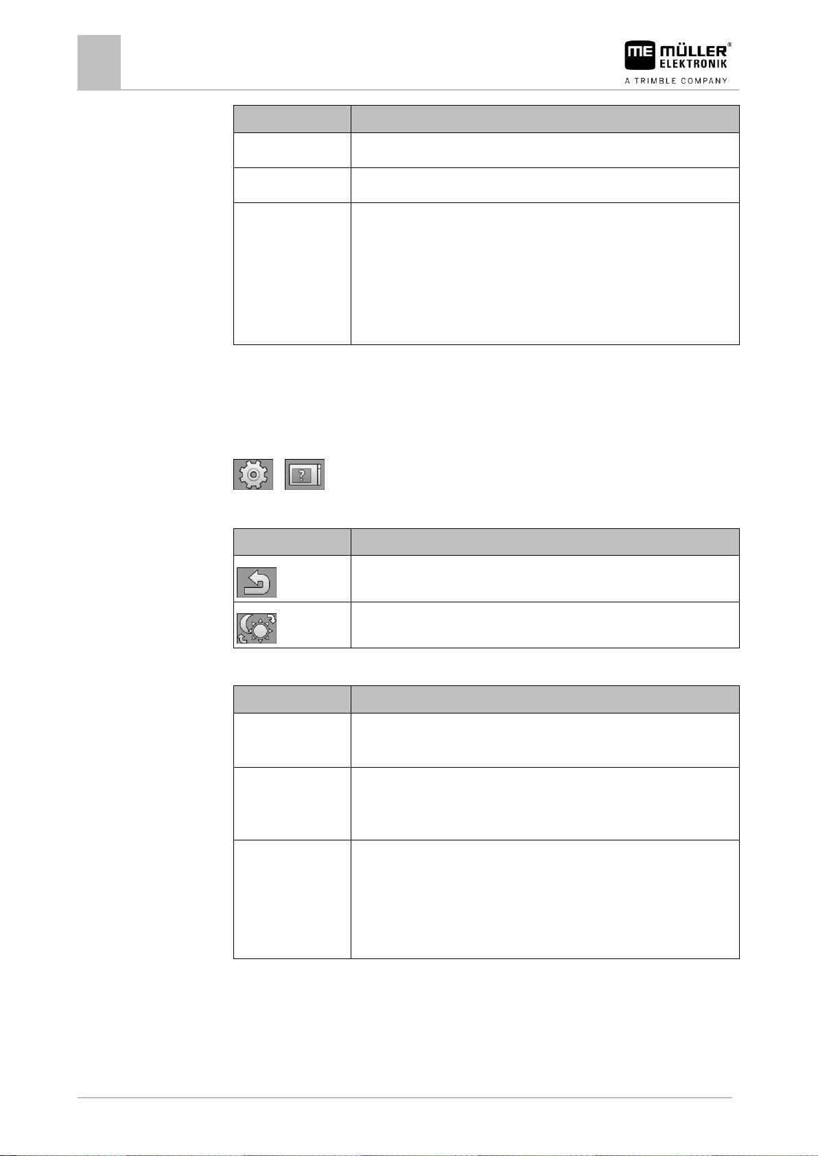
6.3.1
Path
Controls
Parameter
Formats and units
On this screen, you can change different format and unit settings for the terminal.
On the start screen, press:
> .
The following function icons appear on the screen:
The following parameters can be configured on this screen:
Page 20
6
Configuration of the terminal
System settings
20
V8.20220707
30322507-02-EN
Parameter
Meaning
Date format
Date format for the terminal.
Decimal symbol
Decimal symbol for the terminal.
System of units
Unit system in which the terminal is operated.
Metric - Sets the units to the metric system.
Imperial - Sets the units to the imperial system.
US - Sets the units to the US system.
Custom - The units can be configured individually.
Function icon
Meaning
Switches back to the previous screen.
Changes the brightness mode.
Parameter
Meaning
Function ISO VT
Activates and deactivates the login of the VT functionality through the
ISOBUS interface.
Instance ISO VT
If there are multiple terminals on the ISOBUS, each terminal can be
assigned with an instance number. The instance number serves to assign
job computers to terminals.
Number of navigation
buttons
With "1", the terminal uses button 12 for displaying the next function icons, if
the job computer want to display more than 12 function icons at the same
time.
With "2", the terminal uses button 12 for displaying the next function icons
and button 11 for displaying the previous function icons.
6.3.2
Path
Controls
Parameter
6.3.3
Terminal
On this screen, you can define how the terminal should identify itself and react on the bus.
On the start screen, press:
> .
The following function icons appear on the screen:
The following parameters can be configured on this screen:
Vehicle
On this screen, you can configure the following sensors:
▪ Work position sensor
▪ Speed sensor
Page 21
Configuration of the terminal
System settings
6
30322507-02-EN
V8.20220707
21
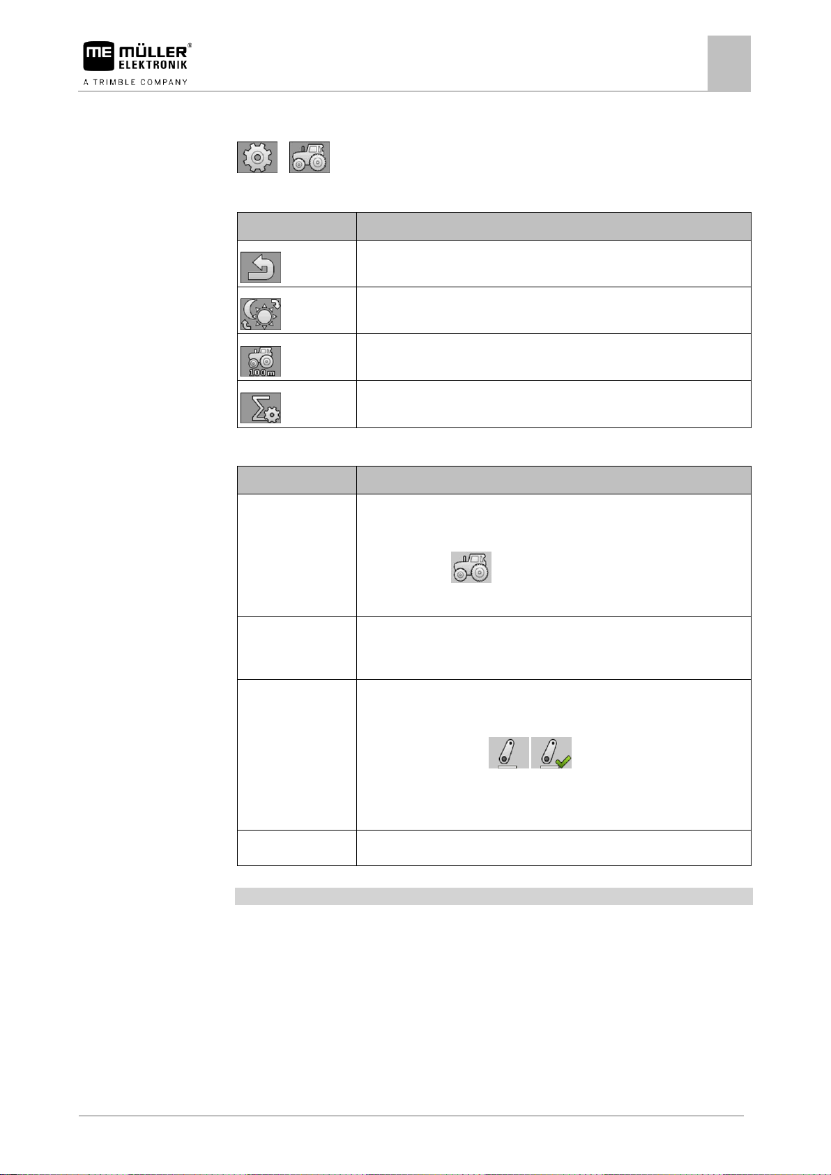
Function icon
Meaning
Switches back to the previous screen.
Changes the brightness mode.
Calls up the screen for calibrating the speed sensor.
Calls up the screen with the counters.
Parameter
Meaning
Speed signal
Source for the speed signal.
Sensor - A speed sensor is connected to the terminal. The work screen
displays the icon: .
CAN-Bus - The speed signal is received through the CAN bus.
Pulses per 100 m
Number of impulses sent by the speed sensor over a distance of 100m.
(Only appears when "Sensor" is selected as the speed signal.)
Work position signal
Source for the work position signal.
Sensor - A work position sensor is connected to the terminal. The start
screen displays the icon: /
CAN-Bus - A work position signal is received through the CAN bus.
No selection - A work position signal was not selected.
Working width in m
Current working width.
Path
Controls
Parameter
Procedure
On the start screen, press:
> .
The following function icons appear on the screen:
The following parameters can be configured on this screen:
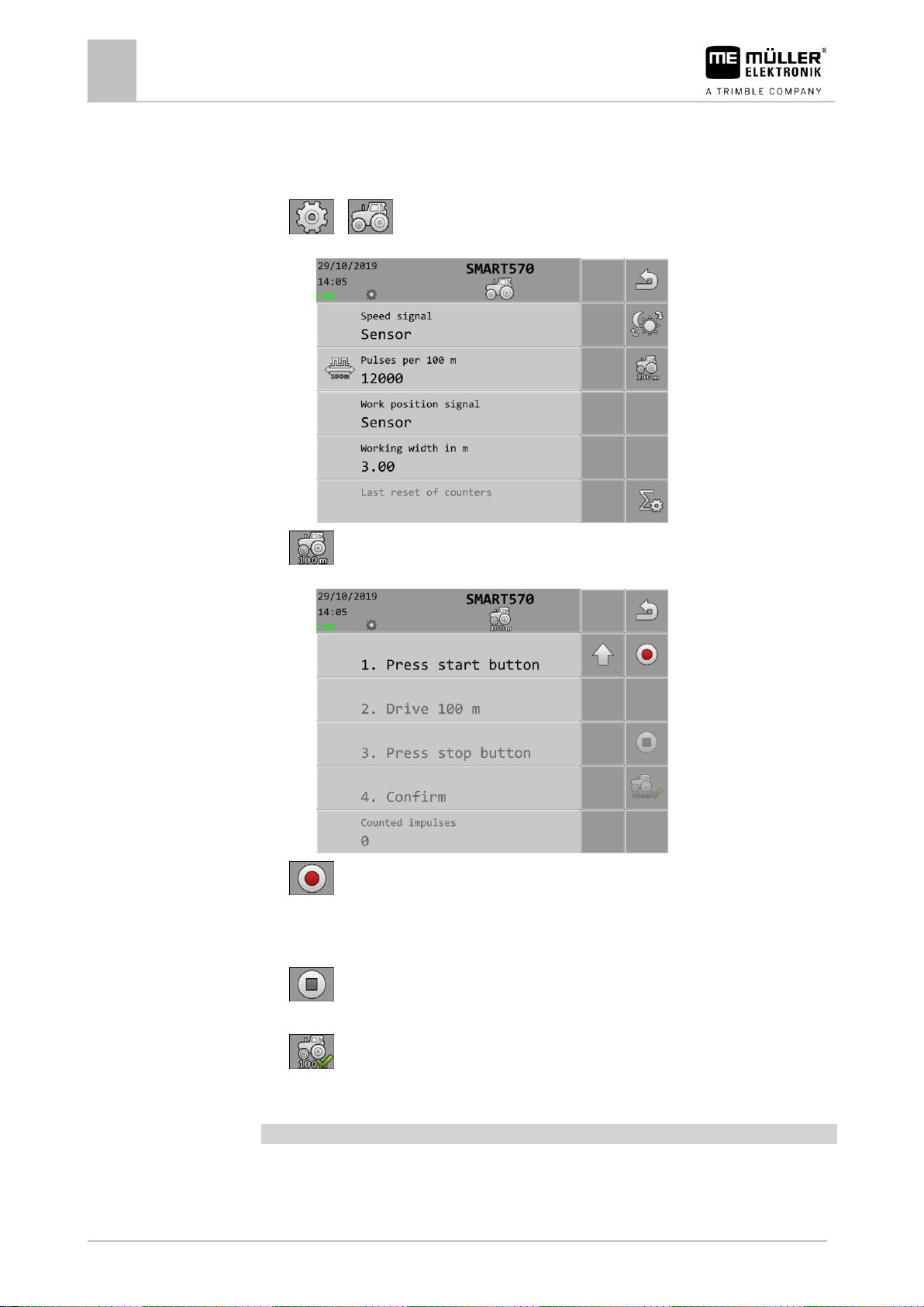
Calibrating the speed sensor
When calibrating the speed sensor, you determine the number of pulses sent by the sensor over a
distance of 100m.
If the number of pulses is known, the terminal can calculate the current speed and transmit it to the
connected job computer.
To calibrate the speed sensor:
The terminal is connected to the tractor signal socket.
In the "Speed signal" parameter, the "Sensor" value is selected.
Page 22
6
Configuration of the terminal
System settings
22
V8.20220707
30322507-02-EN
Path
1. Measure and mark a distance of 100 m. The ground must correspond to the field conditions. The
distance should therefore lead over a meadow or a field.
2. Position the vehicle with connected implement at the beginning of the marked distance.
3. > - Open the vehicle screen.
⇨ The following screen appears:
4. - Open the calibration screen.
⇨ The following screen appears:
5. - Start the calibration.
6. Drive straight ahead over the marked distance.
7. Stop after 100 m.
8. - Terminate the calibration.
⇨ The number of impulses appears on the “Counted impulses” line.
9. - Save the result.
⇨ You have calibrated the speed sensor.
Counters
You can change different counter data on this screen.
On the start screen, press:
Page 23
Configuration of the terminal
Button assignment for AUX operating devices
6
30322507-02-EN
V8.20220707
23
Function icon
Meaning
Switches back to the previous screen.
Resets all counters, except for the operation hours, back to 0.
Parameter
Meaning
Applied area in ha
Applied area since the last counter reset.
Applied distance in
km
Applied distance since the last counter reset.
Working time in h
Working time since the last counter reset.
Service hours
Time during which the terminal was in operation.
Last reset of counters
Date of the last counter reset.
Controls
Parameter
6.4
> >
The following function icons appear on the screen:
The following parameters can be configured on this screen:
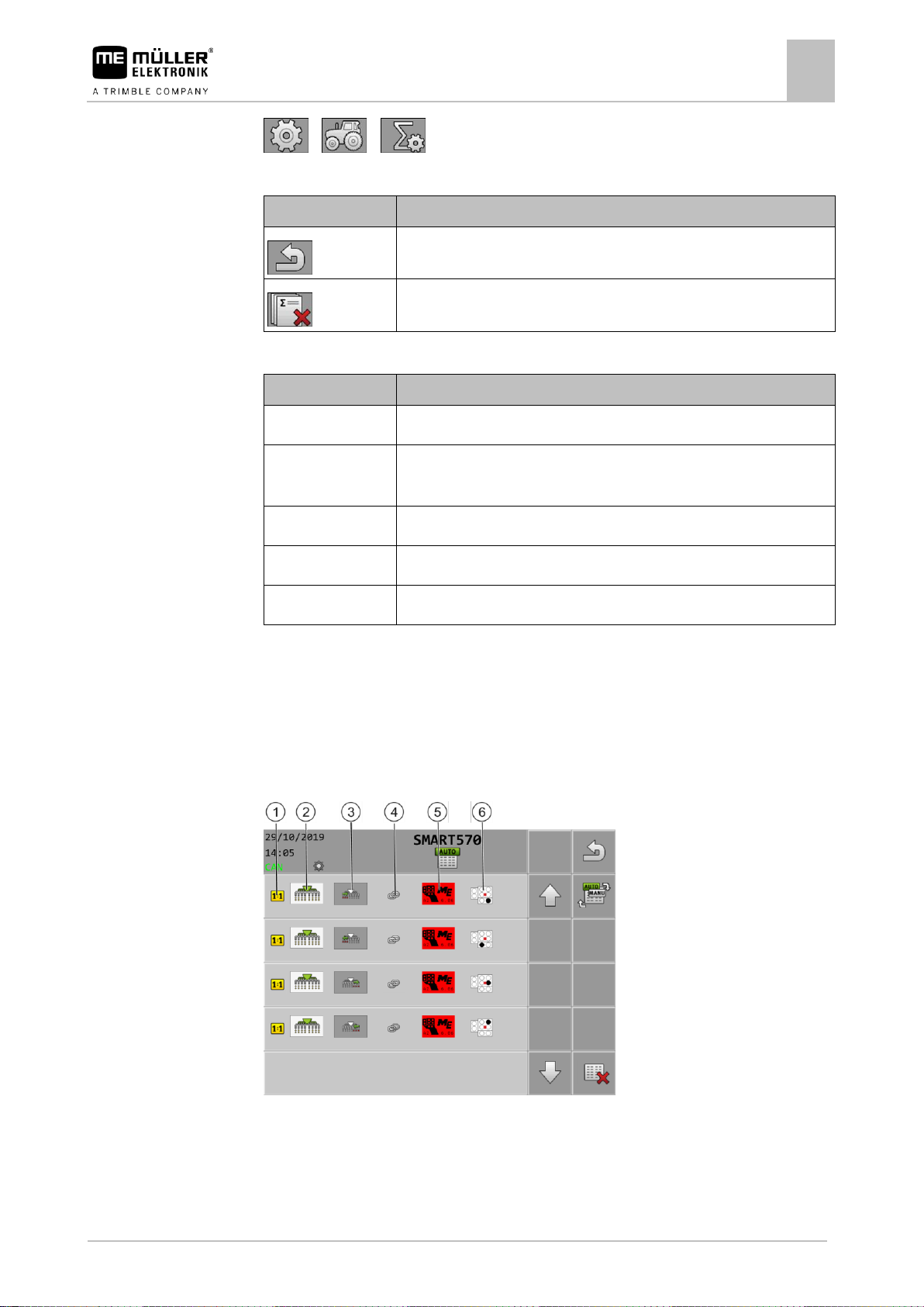
Button assignment for AUX operating devices
The terminal offers you the possibility of assigning the functions of an ISOBUS job computer to the
buttons of the joystick. To do so, the ISOBUS job computer and the joystick must fulfil the Auxiliary 2
specification requirements from the ISOBUS standard.
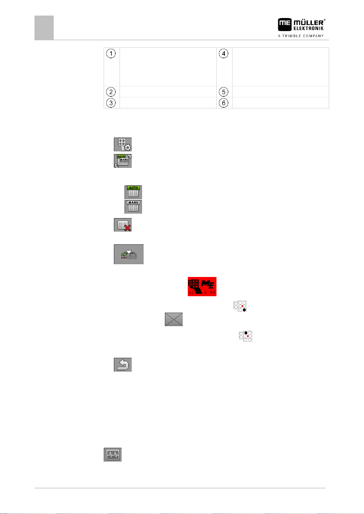
The configuration screen for the button assignment is structured as follows:
Page 24
6
Configuration of the terminal
Diagnostics
24
V8.20220707
30322507-02-EN
Indicates that the respective functions must be
assigned exclusively to a certain button. Some
job computers allow the assignment of
multiple functions to one button; in this case,
this icon is hidden.
Link symbol between the job computer and
joystick
Icon for the job computer
Selected joystick
Job computer function
Assigned button
Procedure
6.5
Path
Controls
The joystick and ISOBUS job computer are connected.
1. On the start screen, press:
2. - Select whether you want to make the assignments directly by pressing the buttons on
the joystick or through the terminal.
⇨ In the upper area of the screen, you can see the assignment mode:
- Assignment is performed directly by pressing the buttons on the joystick.
- Assignment is performed through the terminal.
3. - Optionally, you can delete all of the current button assignments.
4. Search for the job computer function that you want to assign to a button, for example:
.
5. If the function has not yet been assigned to a button, select the joystick to which you want to
assign the function, for example: .
6. Press on the current button assignment, for example: . If there is no button assignment yet
for the function, press: .
7. Select the desired new button assignment, for example: .
8. Repeat this procedure for all desired assignments.
9. - Exit the screen to save the assignments.
⇨ You have completed the assignments and can now operate the machine with the joystick.
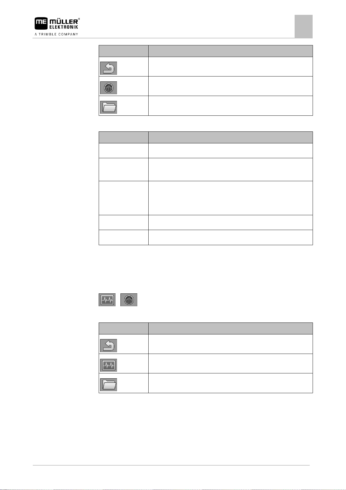
Diagnostics
On this screen, you are given diagnostics information regarding the terminal.
Moreover, the screen shows detailed information on the devices connected to the bus.
On the start screen, press:
The following function icons appear on the screen:
Page 25
Configuration of the terminal
Diagnostics
6
30322507-02-EN
V8.20220707
25
Function icon
Meaning
Switches back to the previous screen.
Switches to the screen with the diagnostics data for the connected devices.
Switches to the screen for deleting object pools.
Parameter
Meaning
Supply voltage
Current supply voltage.
Operating
temperature
Current processor temperature.
Available/used
memory
Currently free and used memory.
If there is no more available memory, you must delete one or more object
pools.
Speed impulses
Currently measured speed impulses per minute.
Work position sensor
Current impulses that are being transmitted by the work position sensor.
Function icon
Meaning
Switches back to the previous screen.
Switches to the diagnostics screen of the terminal.
Switches to the screen for deleting object pools.
Parameter
6.5.1
Path
Controls
The following parameters can be configured on this screen:
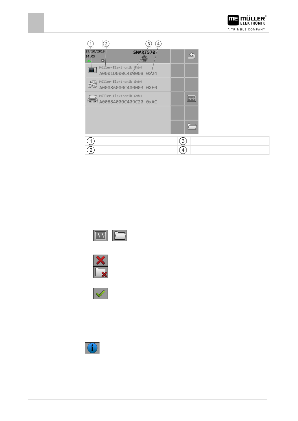
Diagnostic of connected devices
On this screen, you can find detailed information on all of the devices connected to the bus.
On the start screen, press:
> .
The following function icons appear on the screen:
The following information can be found on the screen:
Page 26
6
Configuration of the terminal
Information
26
V8.20220707
30322507-02-EN
Symbol for the respective device type
ISO name
Manufacturer
CAN bus address
6.5.2
Procedure
6.6
Path
Controls
Deleting the object pool
Each job computer that is connected to the ISOBUS copies the images, texts and other objects used
in its software onto the terminal. These files are collectively referred to as object pool.
Since the memory on the terminal is limited, it is sensible to delete the object pools for job computers
that are not in use.
To delete an object pool:
1. On the start screen, press:
>
2. Select the device for which you want to delete files from the terminal memory.
3. - Delete the files.
- Alternatively, delete all of the object pools at the same time.
⇨ A message appears.
4. - Confirm.
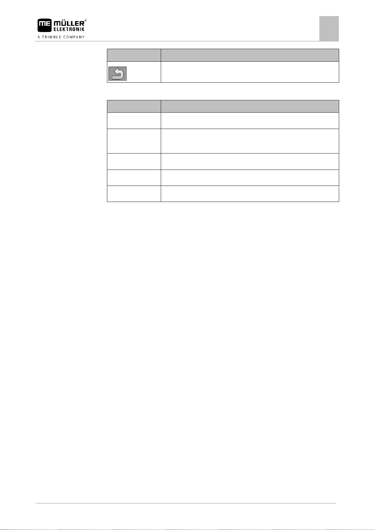
Information
On this screen, you are given information regarding the terminal.
On the start screen, press:
The following function icons appear on the screen:
Page 27
Configuration of the terminal
Information
6
30322507-02-EN
V8.20220707
27
Function icon
Meaning
Switches back to the previous screen.
Parameter
Meaning
Product name
Product name of the terminal.
Item number/serial
number
Item number and serial number of the terminal.
Hardware version
Terminal hardware version.
Software version
Currently installed software version on the terminal.
Firmware version
Currently installed firmware version on the terminal.
Parameter
The following parameters can be configured on this screen:
Page 28
7
Technical specifications
Technical specifications of the terminal
28
V8.20220707
30322507-02-EN
Operating voltage
9 – 16 V, ⎓
Ambient temperature
-20 – +55 °C
Storage temperature
-30 – +85 °C
Weight
Approx. 850 g without bracket
Dimensions (W x H x D)
212 mm x 135 mm x 44 mm
Ingress protection code
IP6K6 in accordance with ISO 20653
EMC
In accordance with 14982
ESD protection
In accordance with 10605
Current consumption
Approx. 350 mA
Processor
32 Bit STM F767 216 MHz
RAM
16 MB
Boot USB
18 MB
Operating system
RTX
Display
5.7“ VGA (640 x 480 px) colour screen with capacitive dual touch
Additional operation
Rotary encoder and membrane keyboard
Housing
PC-ABS
Pin
Signal
Meaning
1
ECU_PWR
Supply +12 V
2
CAN_L_In
CAN Input
3
CAN_L_Out
CAN Output
4
CAN_H_In
CAN Input
5
CAN_H_Out
CAN Output
7
7.1
7.2
7.2.1
Technical specifications
Technical specifications of the terminal
Pin assignment
9-pin CPC connector
Page 29
Technical specifications
Pin assignment
7
30322507-02-EN
V8.20220707
29
Pin
Signal
Meaning
6
TBC_PWR
Ignition Input
7
ECU_PWR
Supply +12 V
8 Not connected
9
ECU_GND
Ground
Pin
Signal
Meaning
1 Not connected
2
DI_In1
Speed sensor input
3 Not connected
4
GND
Ground
5
DI_In2
Work position sensor input
7.2.2
5-pin M12 connector
Page 30
8
Appendix
Updating the terminal
30
V8.20220707
30322507-02-EN
8
8.1
Procedure
Appendix
Updating the terminal
When you want to update the software on the terminal, proceed as follows:
You have a new software version for installation.
You have the Downloadmanager 2 software on your PC and you have connected the PC to the
terminal.
or
You have connected a Downloadbox to the terminal.
You have no other ISOBUS components connected to the ISOBUS.
The terminal is switched off.
1. Start the Downloadmanager 2, if you use it with the PC.
2. + - Press these buttons simultaneously and hold to start the download mode.
3. - Press and hold this button until the logo appears on the screen.
4. / - In Downloadmanager 2, select the terminal.
5. - Mark the terminal.
⇨ An “X” appears in front of the terminal.
6. - Open the folder with update files.
7. - Navigate to the folder containing the update file.
8. / / - Select the update file.
9. - Start the update.
10. Wait until the update has been completed. Do not switch off the terminal during this time.
11. - Return to the list of devices.
⇨ The new software will be loaded.
12. - Switch off the terminal.
13. + - Restart the terminal. Press and hold the buttons for about 3 seconds.
⇨ The terminal reinitializes.
⇨ You have completed the update.
 Loading...