

Page 1

Operating and Installation Guide
UNI-Control, AMATRON II, BMS 2000
on manure carts
Datei: 302102-02_E(ME024452) [06.12.2007]
Version: April 2002
---------------------------
Page 2

Contents
1 Overview .......................................................................... 3
1.1 Pump tank trailer ............................................................................... 3
1.2 Vacuum tank trailer............................................................................ 3
2 System description.......................................................... 4
2.1 Pump tank trailer ............................................................................... 4
2.2 Vacuum tank trailer............................................................................ 4
2.3 Technical data ................................................................................... 5
2.3.1 Flow meter......................................................................................... 5
2.3.2 Ball valve (By-pass valve for the pump trailer)................................... 5
2.3.3 Flat-side valve (cross-section control for vacuum tank trailer) ........... 5
2.3.4 Actuator ............................................................................................. 5
3 Installation instructions .................................................. 6
3.1 UNI Control........................................................................................ 6
3.2 Switch box ......................................................................................... 6
3.3 Signal distributor................................................................................ 6
3.4 16 channel coupler plug .................................................................... 8
3.5 Sensor X (Wheel) .............................................................................. 8
3.6 Sensor Y (working position)............................................................... 9
3.7 Flow meter......................................................................................... 9
3.8 By-pass valve (pump tank trailer) ...................................................... 10
3.9 Flat side valve (vacuum tank trailer) .................................................. 11
3.10 Revolution sensor (pump tank trailer)................................................ 12
4 Safety.............................................................................. 13
4.1 Specified implementation .................................................................. 13
4.2 Safety instructions ............................................................................. 13
5 Operating instructions .................................................. 14
5.1 Switch box ......................................................................................... 14
5.2 Initial operation .................................................................................. 15
5.3 Operating scheme ............................................................................. 16
5.4 Description of the order, machine and operation data
of and the memory............................................................................. 17
Page - 2 - Copyright Müller-Elektronik GmbH u. Co. Operating and Installation Guide UNI-Control on maure carts (04/02)
Page 3
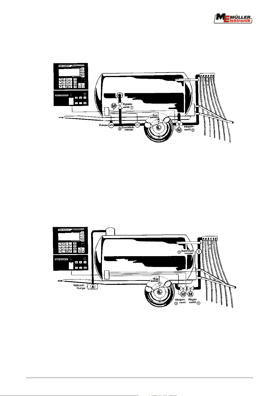
1 Overview
1.1 Pump tank trailer
Function:
Overdose control process: Underdose control process:
> UNI control closes the by-pass > UNI control opens the by-pass
valve in proportion to the dosage error valve in proportion to the dosage error
> Pressure in distribution system rises > Pressure in distribution system falls
> Spread rate increases > Spread rate decreases
1.2 Vacuum tank trailer
Function:
Overdose control process: Underdose control process:
> UNI control closes the by-pass > UNI control opens the by-pass
valve in proportion to the dosage error valve in proportion to the dosage error
> Pressure in distribution system rises > Pressure in distribution system falls
> Spread rate increases > Spread rate decreases
Copyright Müller-Elektronik GmbH u. Co. Operating and Installation Guide UNI-Control manure carts (04/02) Page - 3 -
Page 4

2 System description
Accurate lateral distribution is ensured when using towing tube distributors or slot devices.
Due to high traction power demands there are substantial rate fluctuations especially on hilly ground
and where soil conditions vary frequently.
Fully automatic surface-related regulation of the spread rate using the UNI Control counteracts this
problem. Even on hilly ground with highly varying traction power demands and the resulting
changes in speed, an accurate dosage is guaranteed.
2.1 Pump tank trailer
Behind the pump there is a 3" by-pass to the tank. In this by-pass there is a 3" valve which can be
adjusted via an actuator.
A magnetic inductive flow meter is installed in the tube in front of the towing tube distributor or slot
device.
Once the machine data have been entered the operation process can begin. The current speed and
spread rate are constantly displayed to the driver. If the UNI Control detects a deviation from the
pre-set rate the actuator triggers the by-pass valve.
If the spread rate is too low, the by-pass valve is closed a little. The system pressure is raised and
the spread rate is increased.
If the computer detects that the spread rate is too high, the valve is opened so that the system
pressure is lowered and the spread rate reduced.
2.2 Vacuum tank trailer
In the connection to the towing tube distributor or the slot device an additional flat-side valve is
installed. This can be adjusted by the UNI Control via an actuator.
A magnetic inductive flow meter is installed in the tube in front of the distributor.
Once the machine data have been entered the operation process can begin.
The speed and the current spread rate in cbm/ha are displayed to the driver.
If the UNI Control recognizes that the spread rate is too low, the actuator opens the flat-side valve
further. This causes the pressure at the flat-side valve to be lowered and in the distributor system to
be increased.
The spread rate is increased in this way.
If the UNI Control detects a too high spread rate, the flat-side valve is closed a little.
The spread rate is decreased.
Page - 4 - Copyright Müller-Elektronik GmbH u. Co. Operating and Installation Guide UNI-Control on maure carts (04/02)
Page 5

2.3 Technical data
2.3.1 Flow meter
- Measuring range: nominal width 100 = 0.3 - 3 cbm / min.
nominal width 150 = 0.5 - 5 cbm / min.
- Measuring tolerance: +/- 2 % from the measured rate
- Number of impulses/cbm: 10 000
- minimum conductibility of the measured content > 5 µs/cm
- Ambient temperature: - 10°C bis + 60°C
- max. pressure permitted: 10 bar
- Sandwich connection nach DIN
- Voltage supply: 10 - 16 V = DC
These specifications are taken from the manufacturer's data sheet.
nominal width 125 = 0.4 - 4 cbm / min.
2.3.2 Ball valve (By-pass valve for the pump trailer)
- 3" for a pumping output of up to 3 cbm/min.
- 4 " for pumps with a required output of more than 3 cbm/min.
2.3.3 Flat-side valve (cross-section control for vacuum tank trailer)
Standard flat-side valves matching the respective tube diameter are used.
2.3.4 Actuator
The actuator LA 30.3-200-12 VDC/TD from Linak is used. The stroke is 200 mm.
The max. current consumption is stated to be 18 amperes.
The actuator is protected by a cut-out fuse in the signal distributor.
Copyright Müller-Elektronik GmbH u. Co. Operating and Installation Guide UNI-Control manure carts (04/02) Page - 5 -
Page 6
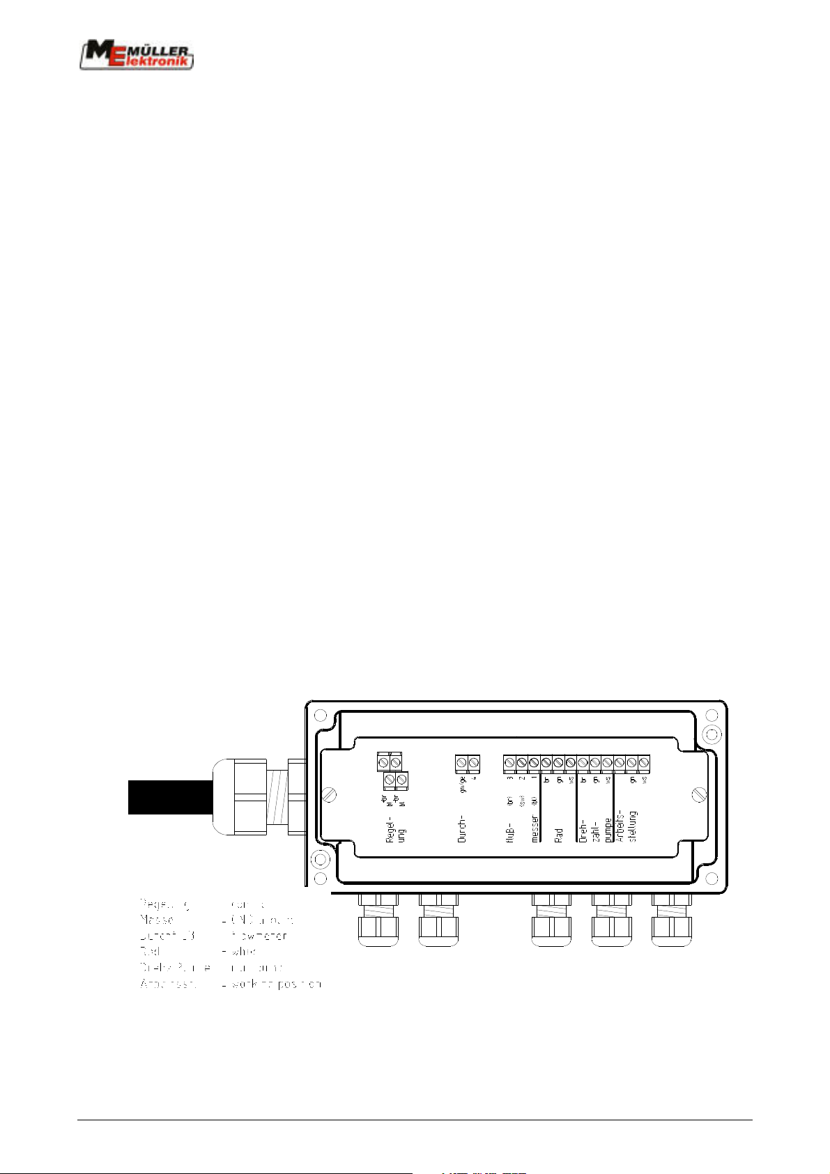
3 Installation instructions
3.1 UNI Control
Please refer to the relevant operating and installation instructions for the installation of the UNI
Control computer.
3.2 Switch box
The switch box is mounted on to the cross pole on the UNI Control in the tractor. Please make sure
that it sits securely and that the electrical connection from the UNI Control to the switch box is safe.
The voltage supply is via the constant current socket on the basic console.
3.3 Signal distributor
The signal distributor is to be installed in an easily accessible position on the manure cart using the
enclosed M4 x 25 screws. The positioning should be chosen so that the distance to the sensors or
to the actuators is as short as possible. The PG screw fittings on the distributor (sensor and
actuator cable)
should point downwards.
All cables can be shortened. However they must be fitted with end sleeves for the strands.
The lid must be closed carefully after installation.
Signal disributor - manure
Page - 6 - Copyright Müller-Elektronik GmbH u. Co. Operating and Installation Guide UNI-Control on maure carts (04/02)
Page 7
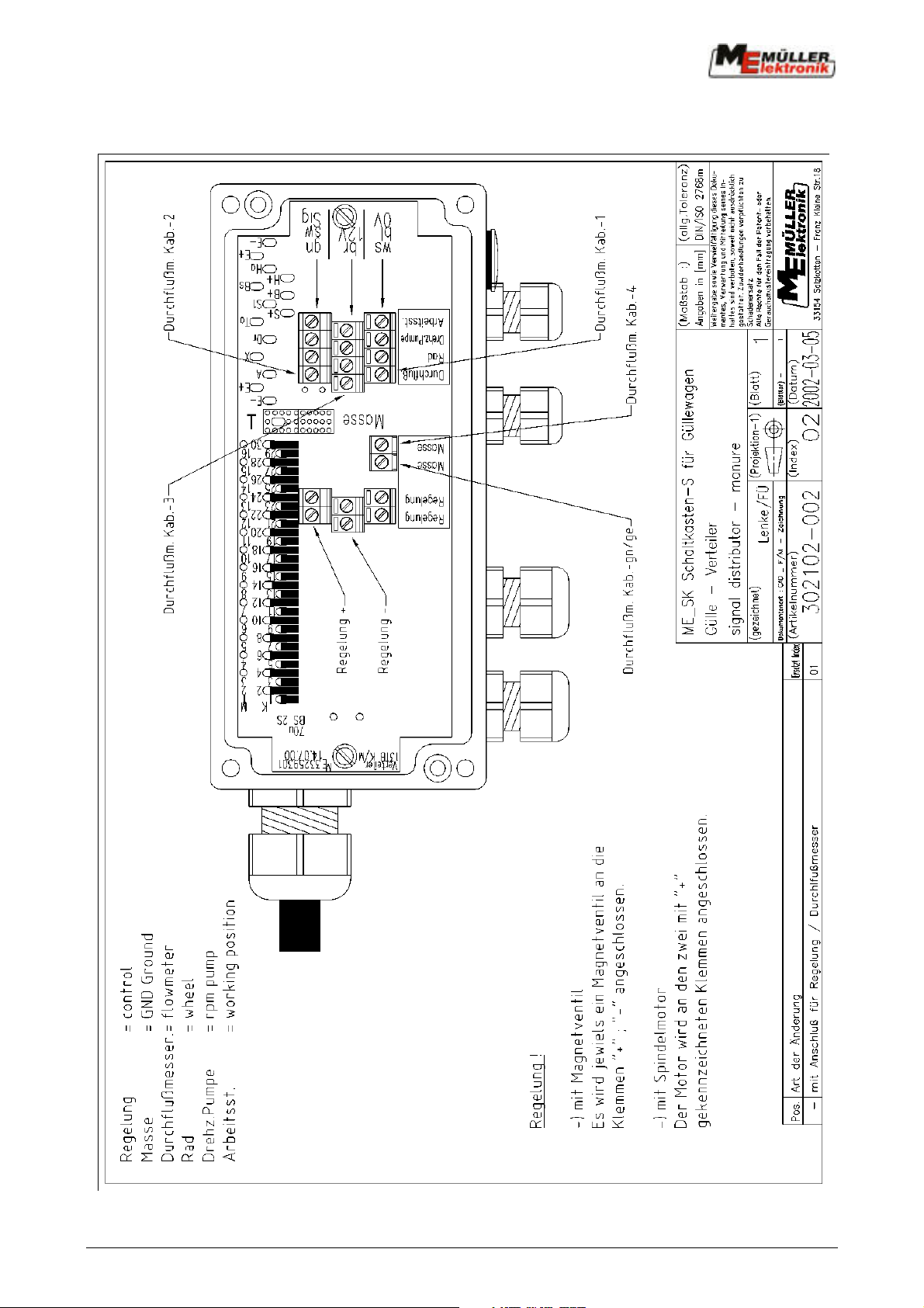
Signal disributor - 2002
Copyright Müller-Elektronik GmbH u. Co. Operating and Installation Guide UNI-Control manure carts (04/02) Page - 7 -
Page 8
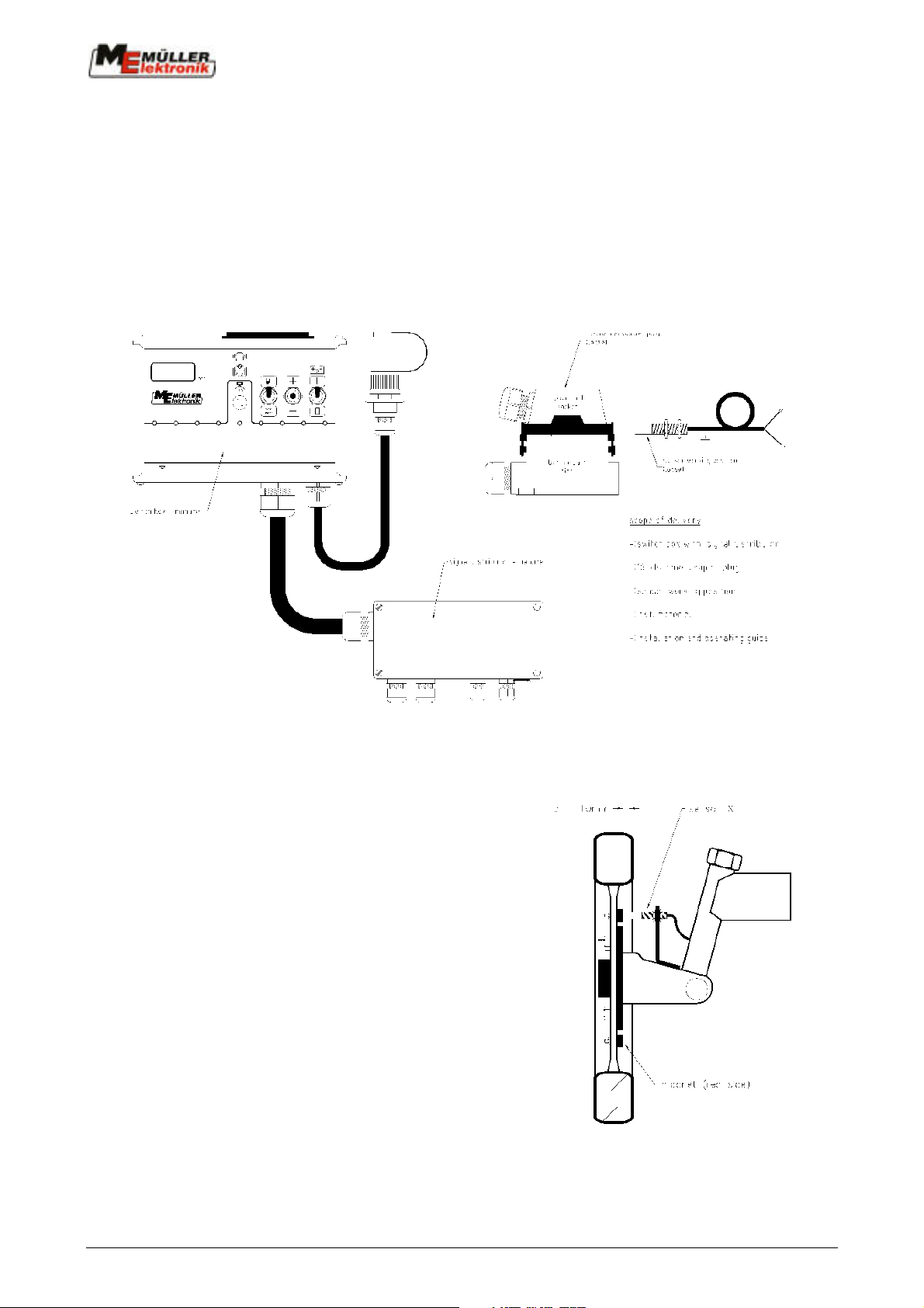
3.4 16 channel coupler plug
The bottom part of the 16 channel coupler plug is to be installed in an easily accessible position at
rhe front of the manure cart, e.g. on the shaft.
The connecting cable from the switch box to the signal distributor is cut through at this point. The
cable from the signal distributor is wired with the pin in the lower part of the coupler plug, lead 1 to
pin 1 etc. End sleeves for the strands must be used.
The cable to the switch box can be shortened if necessary. Installation in the upper section (socket)
of the coupler plug is carried out in the same way as in the lower part.
3.5 Sensor X (Wheel)
The UNI Control needs a signal for the calculation of the
distance travelled. This should be slip-free if possible.
As well as impulse recording from the tractor's front
wheel or cardan shaft and measurement using a radar
device, speed can also be taken from the wheel of the
manure cart or from a free-running wheel.
The magnets are installed in the wheel shell
using the enclosed V4A screws.
They must be distributed as evenly as possible.
The distance travelled from impulse to impulse
must not exceed 60cm.
The number of magnets depends on the size of
the wheel.
Page - 8 - Copyright Müller-Elektronik GmbH u. Co. Operating and Installation Guide UNI-Control on maure carts (04/02)
Page 9

Calculation:
Wheel circumference _ 60cm = number of magnets
e.g.:
256cm _ 60cm = 4.27 = 5 mangnets
The sensor X is mounted vibration-free to a static machine part using the enclosed fixture. The
sensor must point to the side of the magnet painted red (south pole) at a distance of 5 - 10 mm.
The cable is connected in the distributor at the 3 clamps marked "wheel".
brown = br = 12 volt
white = ws = ground
green = gn = signal
3.6 Sensor Y (working position)
If the opening and closing of the eduction valve is not carried out by the UNI Control switch box,
then the sensor Y "working position" is to be installed at the eduction valve.
A magnet is installed at the valve lever. The sensor Y is mounted to a static machine part using the
enclosed fixture. In working position the sensor must point to the red side of the magnet at a
distance of 10 – 20 mm. The control lamp "working position" lights up on the UNI Control.
The cable is connected in the distributor at the clamps marked "working position".
white = ws = ground
green = gn = signal
3.7 Flow meter
The flow meter is positioned in the tube to the distributor system in such a way that only the quantity
which is actually spread flows through the flow meter. In front of the flow meter there must be a
straight piece of tubing with a length of 10 x nominal width (10 x 100 mm = 1 m). Behind the flow
meter a straight piece of tubing with a length of 3 x nominal width is required.
The tube must have the same nominal width as the flow meter. The flow meter is to be mounted
joint-free between the flanges so that no liquid turbulence can develop. The direction of the flow,
marked with an arrow on the flow meter, must be adhered to.
The flow meter can be mounted in a horizontal or perpendicular positioned tube. Preference should
be given to the perpendicular position, as air locks in the liquid have a less negative effect on
measurement accuracy.
Grounding the flow meter
The ground wire from the casing must be connected carefully to the adjacent flange.
In the flange a 5 mm hole is to be bored. The ground wire is connected with the enclosed M5 x 25
V4A screws.
Copyright Müller-Elektronik GmbH u. Co. Operating and Installation Guide UNI-Control manure carts (04/02) Page - 9 -
Page 10
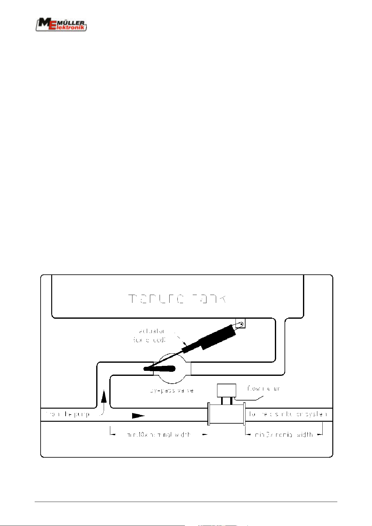
Connection in the distributor.
a) Flow meter
The cable from the flow meter is connected in the distributor at the clamps marked "flow meter".
green-yellow = gnge = operation ground
wire 4 = operation ground
wire 3 = + 12 volt
wire 2 = signal
wire 1 = ground
The lid of the flow meter must not be opened. In the case of violation the guarantee is no longer
binding.
In addition the enclosed manufacturer's operating instructions should be heeded.
b) Inductive pump rotation sensor (only with pump tank trailer) to determine the spread rate
brown = br
black = sw
blue = bl
3.8 By-pass valve (pump tank trailer)
The by-pass valve is installed in the by-pass between the pump flow meter supply tube and the
manure cart. Its purpose is to redirect the surplus quantity from the pump back to the tank. The
optimal positioning is best determined on site at the tank.
Page - 10 - Copyright Müller-Elektronik GmbH u. Co. Operating and Installation Guide UNI-Control on maure carts (04/02)
Page 11
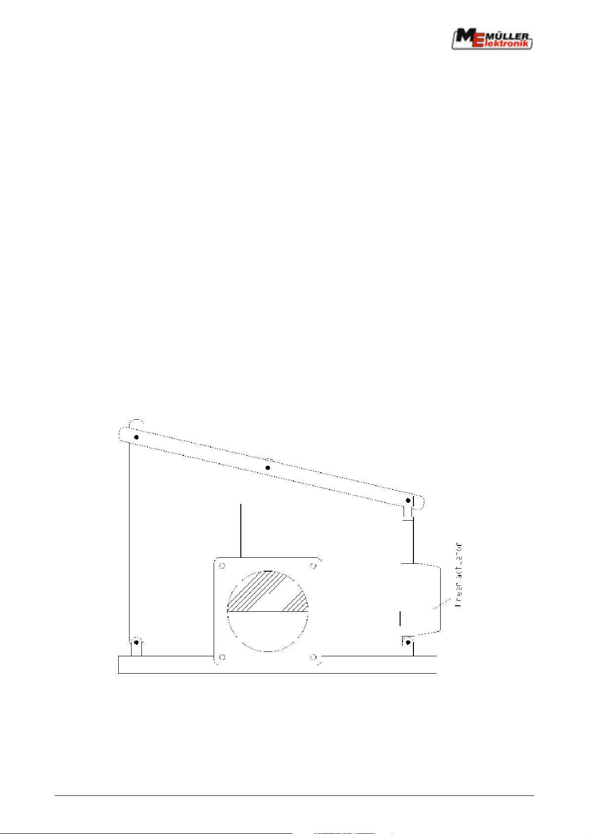
The actuator should be installed so that with an retracted or extended position of the ball valve's
lever an angle of 25° is formed to the actuatior. The engine must run internally on the end stoppers.
The cable from the actuator is connected in the distributor box under ""regulation" at the clamps
marked "+ br" und "- br".
By-pass valve function test
- Switch on switch box
- Switch "Manual/automatic" switch to "manual"
- Press "+" from the "+/-" keys
The by-pass valve should now close. Should it open instead, the two wires from the actuator in the
signal distributor must be replaced.
3.9 Flat side valve (vacuum tank trailer)
The flat side valve is installed in the lead to the distributor system. It's purpose is to supply the
distributor system only with as much liquid as necessary to adhere exactly to the pre-set quantity to
be spread. .
The optimal positioning is best decided on-site at the tank. In some cases it is practical to install the
rcontrol valve (flat side) directly behind the stop valve (flat-side).
The following construction has proved to be satisfactory in practice.
The measurements must be determined on-site depending on the flat-side valve. The engine
should run internally on the minimum and maximum limit
Copyright Müller-Elektronik GmbH u. Co. Operating and Installation Guide UNI-Control manure carts (04/02) Page - 11 -
Page 12

Note!
The construction gap should be kept to a minimum. The cable from the actuator is connected in the
distributor system under "regulation".
Flat-side valve function test:
- Switch on switch box
- Switch "Manual/automatic" switch to "manual"
- Press "+" from the "+/-" keys
The flat-side valve should now open. Should it close instead the two wires from the actuator in the
signal distributor must be replaced.
3.10 Revolution sensor (pump tank trailer)
If required the current power take-off shaft r.p.m. can be displayed on the UNI Control simply by
pressing a key.
Sensor revolution power take-off shaft (Art. No.: 302 580)
For this purpose the sensor is to be installed at the pump drive.
Installation:
- The plastic disc with the integrated magnet is pushed on to the pump's drive shaft and secured
with the grub screws.
- The sensor is installed using the enclosed fixture. It must point towards the magnets. The
distance is to be between 3 and 5 mm.
The cable is connected in the signal distributor under "pump revolutions"
Brown = br = + 12 volt
white = ws = ground
green = gn = signal
Page - 12 - Copyright Müller-Elektronik GmbH u. Co. Operating and Installation Guide UNI-Control on maure carts (04/02)
Page 13

4 Safety
4.1 Specified implementation
The device is specified exclusively for use in agriculture. Any application outwith this area is
regarded as unspecified.
The manufacturer does not accept liability for damage to persons or property resulting from
unspecified use. In such cases all risks are the responsibility of the user.
Specified implementation also includes adhering to the operation and maintenance conditions
stipulated by the manufacturer in the operating instructions.
Relevant accident prevention regulations as well as other generally recognized safety, industrialmedical and road traffic rules are to be adhered to. In addition the manufacturer accepts no liability
in cases where arbitrary modifications have been made to the system.
4.2 Safety instructions
Before working on the electrical system or carrying out any welding operations on the tractor or on
an attached implement, the battery connection must be interrupted.
Copyright Müller-Elektronik GmbH u. Co. Operating and Installation Guide UNI-Control manure carts (04/02) Page - 13 -
Page 14
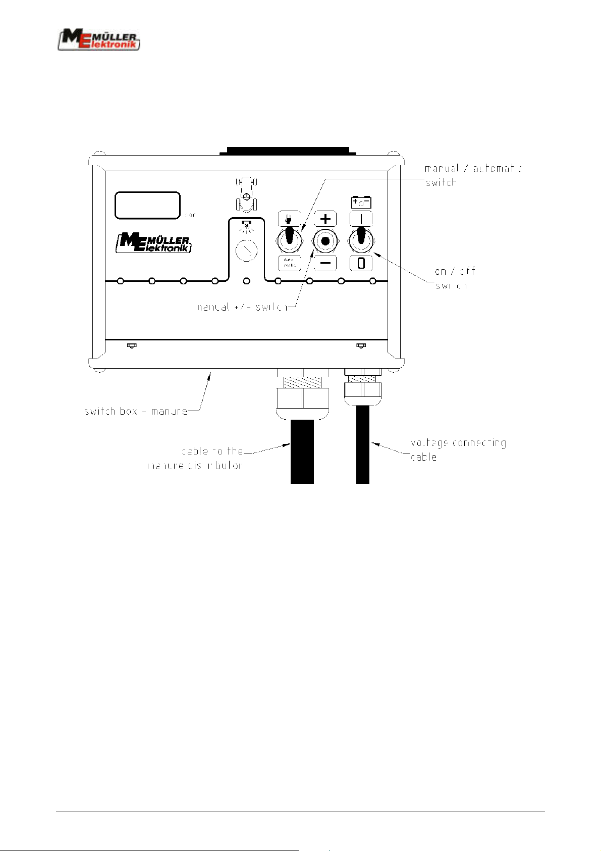
5 Operating instructions
5.1 Switch box
- Switch "Voltage on-off "
The voltage for the switch box and signal distributor is switched on and off here.
- Switch "Manual/Automatic" and "+/-" keys
If the "Manual/Automatic" switch is at manual, the control valve can be operated using the +/keys.
+ Spread rate is increased
- Spread rate is decreased
In the "Automatic" position the control valve is regulated by the UNI Control.
- Main switch
This switch is only available when the stop valve on the manure cart is regulated by an electric
motor or electrohydraulically.
Page - 14 - Copyright Müller-Elektronik GmbH u. Co. Operating and Installation Guide UNI-Control on maure carts (04/02)
Page 15

5.2 Initial operation
Before initial operation the layout of the cables and the installation of the sensors and the actuators
should be checked.
The first test should be carried out with water. .
Procedure:
- Enter machine and order data in to the UNI Control (5.4) and set the pre-set rate to 0.
- Start the order (5.4.)
- Set the switch box to manual operation.
- Select the data block "operation data".
- Drive the tractor. The control lamp "journey" should flash on the UNI Control. The speed is shown
on the display.
- Switch on the manure tank. The control lamp "working position" should light up on the UNI
Control. The spread rate is shown on the display (cbm/ha).
- Vary the quantity using the +/- keys on the switch box. The display (cbm/ha) corresponds to the +/-
key position.
- Enter a pre-set rate e.g. 20 cbm/ha in the UNI -Control (order data). The computer should now
maintain this pre-set rate even when speed varies.
If the regulation is too sluggish the control constant (machine data) should be increased.
Experience at present shows the optimal rate to be between 20 and 40.
- Repeat the test with manure.
Copyright Müller-Elektronik GmbH u. Co. Operating and Installation Guide UNI-Control manure carts (04/02) Page - 15 -
Page 16
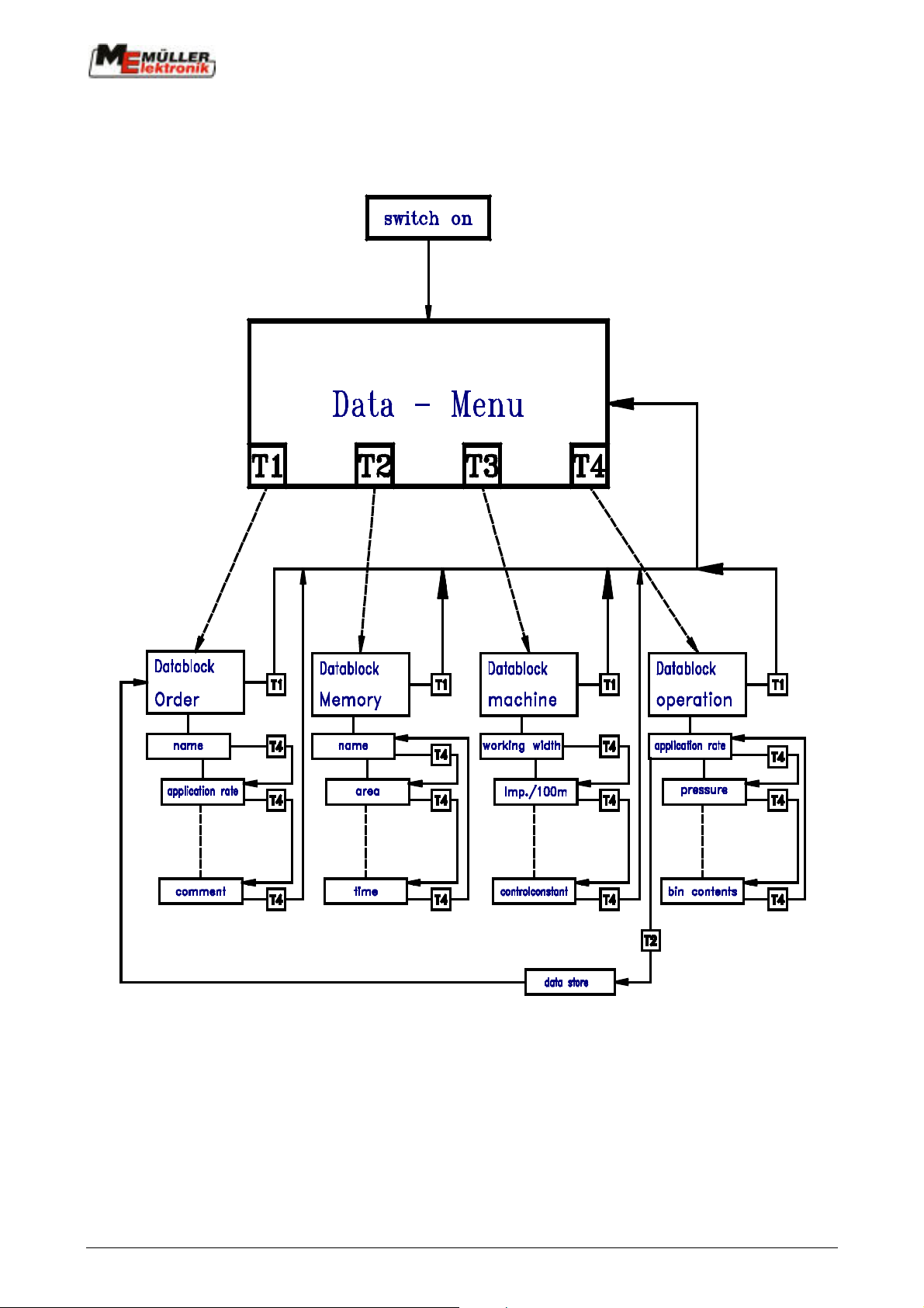
5.3 Operating scheme
Page - 16 - Copyright Müller-Elektronik GmbH u. Co. Operating and Installation Guide UNI-Control on maure carts (04/02)
Page 17

5.4 Description of the order, machine and operation data
of and the memory
The operation procedure for initial operation is described here. The display together with the
adjacent soft keys are depicted:
Left : User guidance and information display
Right : Description of the soft keys
Abbreviations of the data blocks
Me = Menu selection
Au = Order data block
Sp = Memory data block
Ma = Machine data block Note!
Ar = Operation data block
Error-free operation with the manure
cart is guaranteed as of 07.01.1992.
Manure cart program
Switch on
|
v
"on" switch
|
|
v /-----------------/-----┐
┌-------------------------/-----------------/ |
| 0 7 : 0 1 : 9 2 | D u t c h | T1 |
|-------------------------|-----------------|------|
| 1 : 0 0 | F r e n c h | T2 |
|-------------------------|-----------------|------|
| M a n u r e c a r t | E n g l i s h | T3 |
|-------------------------|-----------------|------|
| s w i t c h e d o n | G e r m a n | T4 |
└-------------------------\-----------------\ |
| \-----------------\-----┘
|
|-Order started,
| Working position "on"-------------------- Ar
|
|-Order not yet started --------------┐
| |
v |
Order started |
Working position "off" |
| |
|<------------------------------------|---(Me)
v |
Menu selection (Me)
| |
| |
| |
v /-----------------/-----┐ |
┌-------------------------/-----------------/ | |
| S e l e c t i o n | O r d e r | T1 |---> Au |
|------------------------|-----------------|-------| |
| | M e m o r y | T2 |---> Sp |
|------------------------|-----------------|-------| |
| M e n u | M a c h i n e | T3 |---> Ma |
|------------------------|-----------------|-------| |
| |O p e r a t i o n| T4 |---> Ar |
└-------------------------\-----------------\ | |
\-----------------\-----┘ |
|
|
V
Left:
Program creation date and version,
name of the machine connected
Right:
Select the required language.
|
Left:
"Menu selection" displayed.
Press the T1 key "Menu" from any display
position in order to switch to the menu
selection.
Then press the T1 to T4 keys to select the
data block required.
Right:
Press the T1 key to go to the order data.
Press the T2 key to go to the memory.
The orders which have been already processed
are displayed here (max. 20).
Press the T3 key to go to the machine data.
Press the T4 key to go to the operation
data.
Copyright Müller-Elektronik GmbH u. Co. Operating and Installation Guide UNI-Control manure carts (04/02) Page - 17 -
Page 18

Order data block (Au)
v
|<------------------------------------┘---(Au)
|
v /-----------------/-----┐
┌-------------------------/-----------------/ |
| O r d e r | M e n u | T1 |---> Me
|-------------------------|-----------------|------|
| N o : 5 | S t a r t | T2 |---> Ar
|-------------------------|-----------------|------|
| N a m e / A d r e s s : | | T3 |
|-------------------------|-----------------|------|
| M E Y E R A . B E R G | C o n t i n u e | T4 |---┐
└-------------------------\-----------------\ | |
\-----------------\-----┘ |
|
|
┌-------------------------------┘
|
v /-----------------/-----┐
┌-------------------------/-----------------/ |
| O r d e r | M e n u | T1 |---> Me
|-------------------------|-----------------|------|
| A p p l i c. r a t e | S t a r t | T2 |---> Ar
|-------------------------|-----------------|------|
| S e t r a t e | | T3 |
|-------------------------|-----------------|------|
| 2 0 c b m / h a | C o n t i n u e | T4 |--------┐
└-------------------------\-----------------\ | |
\-----------------\-----┘ |
|
┌------------------------------------┘
|
v /-----------------/-----┐
┌-------------------------/-----------------/ |
| O r d e r | M e n u | T1 |---> Me
|-------------------------|-----------------|------|
| C o m m e n t: | S t a r t | T2 |---> Ar
|-------------------------|-----------------|------|
| L i g h t r a i n | | T3 |
|-------------------------|-----------------|------|
| | C o n t i n u e | T4 |---┐
└-------------------------\-----------------\ | |
\-----------------\-----┘ |
|
┌-------------------------------┘
|
v /-----------------/-----┐
┌-------------------------/-----------------/ |
| O r d e r | M e n u | T1 |---> Me
|-------------------------|-----------------|------|
| M a c h i n e | S t a r t | T2 |---> Ar
|-------------------------|-----------------|------|
| N o : 1 | D e l e t e | T3 |
|-------------------------|-----------------|------|
| F i e l d s p r a y e r| C o n t i n u e | T4 |---> Me
└-------------------------\-----------------\ |
\-----------------\-----┘
Left:
Order number, automatically allocated by
the board computer, is displayed.
Enter the customer's name or the field
using the alphabetical keyboard.
Note: Press the enter key to end the entry!
Right:
Press the T1 key to go to menu selection.
With the T2 key the order is started
(without entry of the set rate and comment),
automatic move to the operation data.
Left:
Enter the required set rate using the
decimal keyboard.
Right:
Press the T1 key to go to menu selection.
With the T2 key the order is started
(without entry of the comment, automatic
move to the operation data.
Left:
Any text can be entered using the
alphabetical keyboard.
It will be stored as comment.
Right:
Press the T1 key to go to menu selection.
With the T2 key the order is started,
automatic move to the operation data.
Press the T4 key to proceed to the next
display.
Left:
With the initial operation of each machine,
the machine number is automatically
allocated and also later automatically
selected, i.e. no entry is needed! If
however there is a 2nd field sprayer with
different machine data the next free machine
number is to be entered for the 2nd sprayer.
In order to activate the 2nd field sprayer's
machine data, its number will be entered
using the decimal keyboard after connecting.
Right:
Press the T1 key to go to menu selection.
With the T2 key the order is started,
automatic move to the operation data.
With the T3 key (delete) the machine data
of the selected machine can be deleted.
Press the T4 key to go to menu selection.
Page - 18 - Copyright Müller-Elektronik GmbH u. Co. Operating and Installation Guide UNI-Control on maure carts (04/02)
Page 19

Machine data block(Ma)
┌----------------------------------------(Ma)
|
|
|
|
|
v /-----------------/-----┐
┌-------------------------/-----------------/ |
|I m p u l s e s/1 0 0 m | M e n u | T1 |---> Me
|-------------------------|-----------------|------|
| 1 8 0 D e v i c e | | T2 |
|-------------------------|-----------------|------|
| 4 7 0 G e a r | C a l i b r . | T3 |-------┐
|-------------------------|-----------------|------| |
| 1 3 1 4 5 R a d a r | C o n t i n u e | T4 |----------┐
└-------------------------\-----------------\ | | |
\-----------------\-----┘ | |
| |
| |
| |
| |
| |
| |
| |
| |
| |
| |
| |
| |
Left:
Displays impulses/100 m, which have been
established by the device attached from the
gear (cardan shaft/wheel)or, if connected,
from the radar sensor.
If there is no sensor connected, the value
corresponding to "Impulses/100 m" must be
set to 0.
Die Sensors have varying levels of
priority. The entry "device" has the
highest (e.g. Recording of impulses from the
wheel of the manure cart). In this case the
entries gear and radar are of no interest to
the computer.
The next priority is the entry "radar"
The entry "gears" has the lowest priority.
Right:
Press the T1 key to go to menu selection.
Calibration is selected by pressing the T3
key.
Press the T4 key to proceed to the next
display.
Description of the calibration process
for impulses/100m
| |
| |
v |
┌-----------------------------------+ |
| ∧ |
v /-----------------/-----┐ | |
┌-------------------------/-----------------/ | | |
| C a l i b r a t i o n | b a c k | T1 |---┐ | |
|-------------------------|-----------------|------| | | |
| d r i v e e x a c t l | y 1 0 0 m , | T2 | | | |
|-------------------------|-----------------|------| | | |
| t h e n s t o p a n d | | T3 | | | |
|-------------------------|-----------------|------| | | |
| p r e s s "e n t e r " | | T4 | | | |
└-------------------------\-----------------\ | | | |
| \-----------------\-----┘ | | |
| | | |
After the 1
| | | |
| | | |
v /-----------------/-----┐ | | |
┌-------------------------/-----------------/ | | | |
| C a l i b r a t i o n | | T1 | | | |
|-------------------------|-----------------|------| | | |
| 1 0 D e v i c e | | T2 | | | |
|-------------------------|-----------------|------| | | |
| 3 5 G e a r | | T3 | | | |
|-------------------------|-----------------|------| | | |
| R a d a r | | T4 | | | |
└-------------------------\-----------------\ | | | |
| \-----------------\-----┘ | | |
| | | |
| | | |
After pressing the enter key | | |
| | | |
|<------------------------------┘ | |
| | |
| | |
| | |
| | |
| | |
v ∧ v
st
impulse | | |
Right:
The calibration process can be interrupted
by pressing the T1 key.
The calibration journey can begin.
After the first impulse from one the of the
3 possible sensors the display opposite
appears automatically.
The impulses are counted continually.
Stop after 100 m and press the enter
key "(=)".
The calibration journey has to be carried
out on the field. Where varying soil
conditions exist, independent calibration
has to be carried out. The rate determined
should be noted and if necessary altered
via the keyboard.
Copyright Müller-Elektronik GmbH u. Co. Operating and Installation Guide UNI-Control manure carts (04/02) Page - 19 -
Page 20

| | |
| | |
| ∧ v
v /-----------------/-----┐ | |
┌-------------------------/-----------------/ | | |
| I m p u l s e s/1 0 0 m | M e n u | T1 |---> Me| |
|-------------------------|-----------------|------| | |
| 2 1 0 D e v i c e | | T2 | | |
|-------------------------|-----------------|------| | |
| 4 7 0 G e a r | C a l i b r . | T3 |-------┘ |
|-------------------------|-----------------|------| |
| R a d a r | C o n t i n u e | T4 |--------->|
└-------------------------\-----------------\ | |
\-----------------\-----┘ v
|
|
┌-------------------------------------┘
|
v /-----------------/-----┐
┌-------------------------/-----------------/ |
| M a c h i n e | M e n u | T1 |---> Me
|-------------------------|-----------------|------|
| W o r k i n g | | T2 |
|-------------------------|-----------------|------|
| w i d t h : | | T3 |
|-------------------------|-----------------|------|
| 1 6 . 0 0 m | C o n t i n u e | T4 |---┐
└-------------------------\-----------------\ | |
\-----------------\-----┘ |
|
|
|
v
┌--------------------------------------┐
| ∧
| |
v /-----------------/-----┐ |
┌-------------------------/-----------------/ | |
| M a c h i n e | M e n u | T1 |---> Me |
|-------------------------|-----------------|------| |
| I m p u l s e s/c b m | | T2 | |
|-------------------------|-----------------|------| |
| | C a l i b r . | T3 |---┐ |
|-------------------------|-----------------|------| | |
| 1 0 0 0 0 | C o n t i n u e | T4 |-------┐ |
└-------------------------\-----------------\ | | | |
\-----------------\-----┘ | | |
| | |
| | |
| | |
┌-------------------------------┘ | |
| | |
v /-----------------/-----┐ | |
┌-------------------------/-----------------/ | | |
| C a l i b r a t i o n | b a c k | T1 |-------|->┘
|-------------------------|-----------------|------| |
| G a u g e c a p a c i t| y (l.) d e t e r| T2 | |
|-------------------------|-----------------|------| |
| m i n e c b m , e n t |e r c b m , | T3 | |
|-------------------------|-----------------|------| |
| P r e s s e n t e r ! | | T4 | |
└-------------------------\-----------------\ | |
| \-----------------\-----┘ |
| |
After the 1. impulse |
| |
| |
v v
Left:
After pressing the enter key the
determined rate is displayed.
Right:
Press the T1 key to go to menu selection.
Calibration can be repeated by pressing the
T3 key.
Press the T4 key to proceed to the next
display.
Left:
Enter the working width using the
decimal keyboard.
Right:
Press the T1 key to go to menu selection.
Press the T4 key to proceed to the next
display
Left:
Enter the impulses/cbm using the decimal
keyboard. The flow meters are calibrated to
10.000 impulses/cbm.
Right:
Press the T1 key to go to menu selection.
If required calibration of the flow meter
can be selected by pressing the T3 key
Press the T4 key to proceed to the next
display.
Description of the calibration process
Right:
The calibration process can be interrupted
by pressing the T3 key.
Page - 20 - Copyright Müller-Elektronik GmbH u. Co. Operating and Installation Guide UNI-Control on maure carts (04/02)
Page 21

| v
| |
| |
v /-----------------/-----┐ |
┌-------------------------/-----------------/ | |
| C a l i b r a t i o n | | T1 | |
|-------------------------|-----------------|------| |
| I m p u l s e s/c b m | | T2 | |
|-------------------------|-----------------|------| |
| 2 8 I m p . | | T3 | |
|-------------------------|-----------------|------| |
| 0 , 0 0 c b m | | T4 | |
└-------------------------\-----------------\ | |
| \-----------------\-----┘ |
| |
| |
| |
v /-----------------/-----┐ |
┌-------------------------/-----------------/ | |
| C a l i b r a t i o n | | T1 | |
|-------------------------|-----------------|------| |
| I m p u l s e s/c b m | | T2 | |
|-------------------------|-----------------|------| |
| 8 2 6 5 6 I m p . | | T3 | |
|-------------------------|-----------------|------| |
| 8 , 2 0 c b m | | T4 | |
└-------------------------\-----------------\ | |
| \-----------------\-----┘ |
| |
| |
| |
| |
| v
| |
v /-----------------/-----┐ |
┌-------------------------/-----------------/ | |
| M a c h i n e | M e n u | T1 |---> Me|
|-------------------------|-----------------|------| |
| I m p u l s e s/c b m | | T2 | |
|-------------------------|-----------------|------| |
| | | T3 | |
|-------------------------|-----------------|------| |
| 1 0 0 8 0 , 0 0 | C o n t i n u e | T4 |------>|
└-------------------------\-----------------\ | |
\-----------------\-----┘ |
|
|
|
┌-----------------------------------┘
|
v /-----------------/-----┐
┌-------------------------/-----------------/ |
| M a c h i n e | M e n u | T1 |---> Me
|-------------------------|-----------------|------|
| T a n k c o n t e n t: | | T2 |
|-------------------------|-----------------|------|
| F u l l : 8 . 2 c b m| | T3 |
|-------------------------|-----------------|------|
| A l a r m : 1 . 0 c b m| C o n t i n u e | T4 |---┐
└-------------------------\-----------------\ | |
\-----------------\-----┘ |
|
|
┌-------------------------------┘
|
v /-----------------/-----┐
┌-------------------------/-----------------/ |
| M a c h i n e | M e n u | T1 |---> Me
|-------------------------|-----------------|------|
| N o. o f n o z z l e | s | T2 |
|-------------------------|-----------------|------|
| B o o m s e c t i o n | 1 | T3 |
|-------------------------|-----------------|------|
| 1 | C o n t i n u e | T4 |---┐
└-------------------------\-----------------\ | |
\-----------------\-----┘ |
|
v
When the manure cart has been switched on
the 1st impulse from the flow meter appears
on the display opposite. The impulses are
counted. The contents of one tank filling
have to be spread.
Before air can get through the flow meter,
close the slide valve.
After the tank contents have been spread
determine the exact amount and enter using
the decimal keyboard.
Left:
After pressing the enter key "(=)"
the computer calculates the rate
"impulses/cbm" and displays it.
Right:
Press the T1 key to go to menu selection.
Press the T4 key to proeceed to the next
display.
The volume meter's impulse count should be
checked a few times each year and especially
at the beginning of each season.
Left:
In order to determine the residue in the
tank, the content and if required an alarm
threshhold value can be entered here.
Right:
Press the T1 key to go to menu selection.
Press the T4 key to proeceed to the next
display.
Left:
As with the field sprayer it is possible to
operate the tank cart with several boom
sections.
If there is no boom section switch, enter
a 1 under "boom section 1". The "boom
section 2" is then acknowledged with a 0.
Right:
Press the T1 key to go to menu selection.
Press the T4 key to proeceed to the next
display.
Copyright Müller-Elektronik GmbH u. Co. Operating and Installation Guide UNI-Control manure carts (04/02) Page - 21 -
Page 22

|
|
┌-------------------------------┘
|
v /-----------------/-----┐
┌-------------------------/-----------------/ |
| M a c h i n e | M e n u | T1 |---> Me
|-------------------------|-----------------|------|
| N o. o f n o z z l e s| | T2 |
|-------------------------|-----------------|------|
| B o o m s e c t i o n | 3 | T3 |
|-------------------------|-----------------|------|
| 0 | C o n t i n u e | T4 |---┐
└-------------------------\-----------------\ | |
\-----------------\-----┘ |
|
|
┌-------------------------------┘
|
v /-----------------/-----┐
┌-------------------------/-----------------/ |
| M a c h i n e | M e n u | T1 |---> Me
|-------------------------|-----------------|------|
| C o n t r o l | | T2 |
|-------------------------|-----------------|------|
| c o n s t a n t : | | T3 |
|-------------------------|-----------------|------|
| 2 0 . 0 0 | C o n t i n u e | T4 |---> Me
└-------------------------\-----------------\ |
\-----------------\-----┘
Left:
Up to a maximum of 10 boom sections can be
taken into account.
If there are e.g. 2 boom sections, the 3
rd
boom section is set to 0 using the decimal
keyboard.
Right:
Press the T1 key to go to menu selection.
Press the T4 key to proeceed to the next.
display.
Left:
The control constant is entered using the
decimal keyboard. If regulation is too
sluggish, the rate has to be increased. In
the case of saturation, i.e. with a set-rate
of 20cbm/ha there is regulation from
16cbm/ha to 23cbm/ha then to 18cbm/ha etc.,
then the control constant is too high. The
entered cart rate must be reduced. Depending
on the manure values varying from 10 to 40
are possible.
Rechts:
Press the T1 and T4 keys to go to menu
selection.
Operation data block (Ar)
┌----------------------------------------(Ar)
|
v /-----------------/-----┐
┌-------------------------/-----------------/ |
| O r d e r | M e n u | T1 |---> Me
|-------------------------|-----------------|------|
| N o : 5 | Y e s | T2 |---┐
|-------------------------|-----------------|------| |
| s t a r t ? | N o | T3 |-->|
|-------------------------|-----------------|------| |
| | | T4 | |
└-------------------------\-----------------\ | |
\-----------------\-----┘ |
|
v
┌-------------------------------+<--- (Ar) when the order has been started.
|
v /-----------------/-----┐
┌-------------------------/-----------------/ |
| 6 . 8 k m / h | M e n u | T1 |---> Me
|-------------------------|-----------------|------|
| | E n d | T2 |---------┐
|-------------------------|-----------------|------| |
| 2 0 0 c b m / h a | T a n k | T3 |------┐ |
|-------------------------|-----------------|------| | |
| + 1 0 % 1 2 . 0 m | C o n t i n u e | T4 |---┐ | |
└-------------------------\-----------------\ | | | |
\-----------------\-----┘ | | |
| | |
| | |
| | |
| | |
| | |
v v v
Left:
The current order number is displayed.
Right:
Press the T1 key to go to menu selection.
The order as well as operation time is
started when the T2 key is pressed.
When the T3 key is pressed the order will
not be started. The journey can be continued
without the working position.
Left:
Relevant information is displayed here
during the operation process:
speed, current spread rate, pre-set
deviation from the set rate entered,
the remaining width when working with
boom sections.
Right:
Press the T1 key to go to menu selection.
Press the T2 key to go to the end of the
order.
Press the T3 key for the tank content
data
Press the T4 key for further operation
data.
Page - 22 - Copyright Müller-Elektronik GmbH u. Co. Operating and Installation Guide UNI-Control on maure carts (04/02)
Page 23

| | |
| | |
┌-------------------------------┘ | |
| | |
v /-----------------/-----┐ | |
┌-------------------------/-----------------/ | | |
| 1 . 6 0 c b m / m i n | M e n u | T1 |--->Me| |
|-------------------------|-----------------|------| | |
| | | T2 | | |
|-------------------------|-----------------|------| | |
| | | T3 | | |
|-------------------------|-----------------|------| | |
| | C o n t i n u e | T4 |--->Ar| |
└-------------------------\-----------------\ | | |
\-----------------\-----┘ | |
| |
| |
| |
┌----------------------------------┘ |
| |
| |
v /-----------------/-----┐ |
┌-------------------------/-----------------/ | |
| 2 0 . 0 c b m / h a | N e . B l o c k | T1 |--->Me |
|-------------------------|-----------------|------| |
| 2 0 0 m | | T2 | |
|-------------------------|-----------------|------| |
| 0 . 3 2 h a | T a n k | T3 |------┐ |
|-------------------------|-----------------|------| | |
| R e s t : 6 . 5 c b m| C o n t i n u e | T4 |--->Ar| |
└-------------------------\-----------------\ | | |
\-----------------\-----┘ | |
| |
| |
| |
┌----------------------------------┘ |
| |
| |
v /-----------------/-----┐ |
┌-------------------------/-----------------/ | |
| T a n k |T . e m p t y | T1 | |
|-------------------------|-----------------|------| |
| f i l l i n g |T a n k f u l l | T2 | |
|-------------------------|-----------------|------| |
| | | T3 | |
|-------------------------|-----------------|------| |
| 8 , 2 c b m | C o n t i n u e | T4 |---> Ar |
└-------------------------\-----------------\ | |
\-----------------\-----┘ |
|
|
|
┌-------------------------------------┘
|
v /-----------------/-----┐
┌-------------------------/-----------------/ |
| E n d | M e n u | T1 |---> Me
|-------------------------|-----------------|------|
| o r d e r a n d | N o | T2 |---> Ar
|-------------------------|-----------------|------|
| s t o r e ? | Y e s | T3 |---> Au
|-------------------------|-----------------|------|
| | | T4 |
└-------------------------\-----------------\ |
\-----------------\-----┘
Left:
Display of the current spread rate in
cbm/min.
Right:
Press the T1 key to go to menu selection.
Press the T4 key to go to the operation
data.
Left:
Display of the current pre-set spread rate,
the residue in the tank and the prognoses
for the distance and area, which have still
to be processed using the remaining amount.
Using the +/-10% keys the pre-set rate can
be set so that the prognoses correspond with
the actual conditions and there is no
residue!
Right:
Press the T1 key to go to menu selection.
Press the T3 key for the tank content data.
Press the T4 key to go to the operation
data.
Left:
The new tank content can be entered here.
Right:
The T1 key acknowldges that the tank is
empty.
The T2 key is pressed when the tank has been
filled up.
Press the T4 key to go to the operation
data.
Any further information required can be
entered using the decimal keyboard.
Left:
The order can be ended and stored here.
Right:
Press the T1 key to go to menu selection.
The current operation data can be selected
by presing the T2 key.
The T3 key is used to store the calculated
data.
Copyright Müller-Elektronik GmbH u. Co. Operating and Installation Guide UNI-Control manure carts (04/02) Page - 23 -
Page 24

Memory data block
┌----------------------------------------(Sp)
|
|
v /-----------------/-----┐
┌-------------------------/-----------------/ |
| M e m o r y : 5 | M e n u | T1 |--->Me
|-------------------------|-----------------|------|
| M E Y E R A . B E R G | D e l e t e | T2 |---------┐
|-------------------------|-----------------|------| |
| M a c h . N r 1 | N. m e m o r y | T3 |---> Sp |
|-------------------------|-----------------|------| |
| M a n u r e c a r t | C o n t i n u e | T4 |---┐ |
└-------------------------\-----------------\ | | |
\-----------------\-----┘ | |
| |
| |
| |
| |
┌-------------------------------┘ |
| |
v /-----------------/-----┐ |
┌-------------------------/-----------------/ | |
| M e m o r y : 5 | M e n u | T1 |--->Me |
|-------------------------|-----------------|------| |
| 7 . 8 1 2 k m | | T2 | |
|-------------------------|-----------------|------| |
| 1 0 . 5 0 h a | | T3 | |
|-------------------------|-----------------|------| |
| 2 1 2 . 0 c b m | C o n t i n u e | T4 |---┐ |
└-------------------------\-----------------\ | | |
\-----------------\-----┘ | |
| |
| |
| |
┌-------------------------------┘ |
| |
v /-----------------/-----┐ |
┌-------------------------/-----------------/ | |
| M e m o r y : 5 | M e n u | T1 |--->Me |
|-------------------------|-----------------|------| |
| 6 . 7 3 h M a c . | | T2 | |
|-------------------------|-----------------|------| |
| 7 . 5 5 h T r a c | | T3 | |
|-------------------------|-----------------|------| |
| 9 . 8 6 h D r i v | C o n t i n u e | T4 |---┐ |
└-------------------------\-----------------\ | | |
\-----------------\-----┘ | |
| |
| |
| |
| |
| |
| |
┌-------------------------------┘ |
| |
v /-----------------/-----┐ |
┌-------------------------/-----------------/ | |
| M e m o r y : 5 | M e n u | T1 |--->Me |
|-------------------------|-----------------|------| |
| C o m m e n t s : | | T2 | |
|-------------------------|-----------------|------| |
| L i g h t r a i n | | T3 | |
|-------------------------|-----------------|------| |
| | C o n t i n u e | T4 |--->Sp |
└-------------------------\-----------------\ | |
\-----------------\-----┘ |
|
v
Left:
The last order to be stored is automatically
displayed.
Right:
Press the T1 key to go to menu selection.
By pressing the T2 key all orders in the
memory are deleted.
The previous order is displayed when the T3
key is pressed.
The order, machine and operation data of
each order can be selected by pressing the
T4 key.
Left:
Further data concerning order number 5
are displayed.
Right:
Press the T1 key to go to menu selection.
The order, machine and operation data of
each order can be selected by pressing the
T4 key.
Left:
Display of operation time
Operation time "Machine" runs when the
machine is in working position.
Operation time "tractor" runs when
the speed exceeds 1 km/h.
Operation time "driver" counts from board
computer switch-on.
Rechts:
Press the T1 key to go to menu selection.
The order, machine and operation data of any
order can be selected by pressing the T4
key.
Left:
Any comments entered are shown on the
display.
Right:
Press the T1 key to go to menu selection.
Press the T4 key to go to memory 4.
Page - 24 - Copyright Müller-Elektronik GmbH u. Co. Operating and Installation Guide UNI-Control on maure carts (04/02)
Page 25

|
|
|
┌-------------------------------------┘
|
v /-----------------/-----┐
┌-------------------------/-----------------/ |
| M e m o r y : | | T1 |
|-------------------------|-----------------|------|
| | N o | T2 |---> Me
|-------------------------|-----------------|------|
| d e l e t e ? | Y e s | T3 |---> Me
|-------------------------|-----------------|------|
| | | T4 |
└-------------------------\-----------------\ |
\-----------------\-----┘
Left:
All orders existing in the memory
can be deleted.
Right:
The memory will not be deleted when the T2
key is pressed.
It is deleted using the T3 key.
Back to menu selection.
Alarm display
┌----------------------------------------(Alarm)
|
v /-----------------/-----┐
┌-------------------------/-----------------/ |
| A L A R M ! | | T1 |
|-------------------------|-----------------|------|
| S e t – r a t e c a n | n o t b e | T2 |
|-------------------------|-----------------|------|
| m a i n t a i n e d ! | | T3 |
|-------------------------|-----------------|------|
| 1 8 c b m / h a | | T4 |
└-------------------------\-----------------\ |
\-----------------\-----┘
Alarm display as soon as the pre-set rate
can no longer be maintained.
Calculator function
┌----------------------------------------(Calculator)
|
v /-----------------/-----┐
┌-------------------------/-----------------/ |
| C a l c u l a t o r | | T1 |
|-------------------------|-----------------|------| the
| _ 0 . 0 0 | | T2 |
|-------------------------|-----------------|------|
| + 0 . 0 0 | | T3 |
|-------------------------|-----------------|------|
| = 0 . 0 0 | b a c k | T4 |--->
└-------------------------\-----------------\ |
\-----------------\-----┘
Left:
The calculator function is selected via
+, -, x or ÷ keys.
The calculator can be used during operation.
Rechts:
Press the T4 key to go back to the program.
Copyright Müller-Elektronik GmbH u. Co. Operating and Installation Guide UNI-Control manure carts (04/02) Page - 25 -
Page 26

Functional data
The 3 function keys beside the decimal keyboard enable required rates to be displayed at any time simply by
pressing a key.
┌---------┐
| kg; l |
┌----------------------------------------| ----- |
| | ha |
| └---------┘
v /-----------------/-----┐
┌-------------------------/-----------------/ |
| 2 2 5 c b m | | T1 |
|-------------------------|-----------------|------|
| | T o t a l | T2 |---------┐
|-------------------------|-----------------|------| |
| 0 , 5 3 7 6 h a | | T3 | |
|-------------------------|-----------------|------| |
| | C o n t i n u e | T4 |---> Ar |
└-------------------------\-----------------\ | |
\-----------------\-----┘ |
|
┌-------------------------------------┘
| ∧
| |
v /-----------------/-----┐ |
┌-------------------------/-----------------/ | |
| 4 8 1 0 c b m | D e l e t e | T1 |-->|
|-------------------------|-----------------|------| |
| | | T2 | |
|-------------------------|-----------------|------| |
| 3 4 3 . 6 9 2 4 h a | D e l e t e | T3 |---┘
|-------------------------|-----------------|------|
| | C o n t i n u e | T4 |---> Ar
└-------------------------\-----------------\ |
\-----------------\-----┘
Left:
Display of the spread rate and the area
worked, valid for the current order.
Right:
By pressing the T2 key the total spread rate
and area worked are displayed.
Press the T4 key to return to the operation
data.
Left:
Display of the total spread rate and
and the area worked
(e.g. in one season).
Right:
The rates opposite are deleted when the T1
and T3 keys are pressed.
Press the T4 key to return to the operation
data.
┌---------┐
| km |
┌----------------------------------------| ----- |
| | h |
| └---------┘
v /-----------------/-----┐
┌-------------------------/-----------------/ |
| 1 2 7 . 3 2 1 k m | | T1 |
|-------------------------|-----------------|------|
| 6 . 7 3 h M a c . | | T2 |
|-------------------------|-----------------|------|
| 7 . 5 5 h T r a c | | T3 |
|-------------------------|-----------------|------|
| 9 . 8 6 h D r i v | C o n t i n u e | T4 |---> Ar
└-------------------------\-----------------\ |
\-----------------\-----┘
┌---------┐
| ha/h |
┌----------------------------------------| ----- |
| | 1/min |
| └---------┘
v /-----------------/-----┐
┌-------------------------/-----------------/ |
| 3 . 3 2 h a / h | | T1 |
|-------------------------|-----------------|------|
| 3 . 0 8 h a / h | | T2 |
|-------------------------|-----------------|------| (
|P o w e r t.–o. s h a f | t | T3 |
|-------------------------|-----------------|------|
| 5 2 0 1 / m i n | C o n t i n u e | T4 |---> Ar
└-------------------------\-----------------\ |
\-----------------\-----┘
Left:
Display of the distance driven and the
operation time for the machine, tractor
and driver, valid for the current order
Right:
Press the T4 key to return to the operation
data
Left:
Display of the current and average
area output.
Pump revolution rate
Pump revolution rate sensor)
Right:
Press the T4 key to return to the operation
data.
Page - 26 - Copyright Müller-Elektronik GmbH u. Co. Operating and Installation Guide UNI-Control on maure carts (04/02)
 Loading...