

Page 1

AMPLIFIER
OWNER’S
MANUAL
RT251D
Page 2

3
AMPLIFIER OWNER’S MANUAL
2
• Intelligent Surface Mount Technology
• Patented PWM MOSFET switching power supply (#5,598,325)
• Adaptive Class D technology
• High powered transformer
• High powered stacked inductor
• Pure N-channel design
• Doubles power into 2 ohms
• Real time computerized protection circuit
• Color-coded wire harness for speaker-level input installation
• Smart-Engage™ auto turn on for easy integration with factory head units
• Acoustically Seamless Turn-on/Turn-off (i.e. no noise)
• Low-pass crossover, 85Hz, 24dB/octave low pass
• Switchable Bass Boost @ 0, 6 or 12dB centered at 40Hz
• Low level inputs
• Adjustable input sensitivity
• Nickel-plated, heavy duty terminal block type connectors
• Unique rubber Insulated Iso-Feet™
Features
Specifications
CONGRATULATIONS...
on your purchase of a new MTX Audio
Road Thunder Amplifier! MTX has long
been the industry leader in mobile audio,
and we have reached new heights with
the development of the new MTX Road
Thunder amplifiers. You couldn’t have
chosen a more reliable, powerful, or
better performing amplifier.
We manufacture every amplifier using
the latest Intelligent Surface Mount
Technology. Some of the advantages of the
new design are its significant improvements
to the amplifier’s electrical and mechanical
properties. ISMT devices feature substantially shorter internal and external lead lengths.
This reduces stray capacitance and inductance, which results in cleaner and more
accurate musical reproduction with significantly less noise interference. The ISMT
mounter produces amplifier boards with
smaller and lighter components, which are
more resistant to vibrations inherent in the
automotive environment.
We want to ensure you get continuous high
performance from your MTX Road Thunder
amplifier, so we recommend that you have it
professionally installed by your authorized
MTX dealer.
HOW TO USE THIS MANUAL
If you are installing this amplifier yourself, we
recommend that you read the manual coverto-cover before you install it. Familiarize
yourself with the features and details on the
input and output panels. Make sure you have
all the equipment you need. Then follow the
step-by-step installation instructions included.
Sample installation diagrams may be found
on our website:
mtx.com
If you have any questions, write or call us:
MTX Audio
4545 E. Baseline Rd. Phoenix, AZ 85042
602-438-4545 • 800-CALL MTX
technical@mtx.com
mtx.com
Please take a moment to register your
purchase online at mtx.com.
Please also record the serial number of
your amplifier in the space provided below
and keep this manual for future reference,
as well as your sales receipt as proof of
ownership. (The serial number of your
amplifier is marked on the bottom of its
metal chassis.)
Serial Number:
Date of Purchase:
Introduction
ENGLISH
RT251D
RMS Power measured at 14.4 Volts DC:
100 Watts x 1 into a 4 Ohm load with less than 1% Thd+N
200 Watts x 1 into a 2 Ohm load with less than 1% Thd+N
Dynamic Power measured at 14.4 Volts DC:
125 Watts x 1 into a 4 Ohm load
250 Watts x 1 into a 2 Ohm load
Signal to Noise Ratio: ≥100dB A-Weighted
Frequency Response: 20Hz-85Hz
Maximum Input: 8Vrms
Bass Boost: Switchable Bass Boost 0, 6, or 12dB centered at 40Hz
Crossover: Fixed @ 85Hz, 18dB/octave low pass
Dimensions: Including Iso-Feet™
7.98" x 9.75" x 2.1" (20.3cm x 24.8cm x 5.3cm)
Page 3
AMPLIFIER OWNER’S MANUAL
4
5
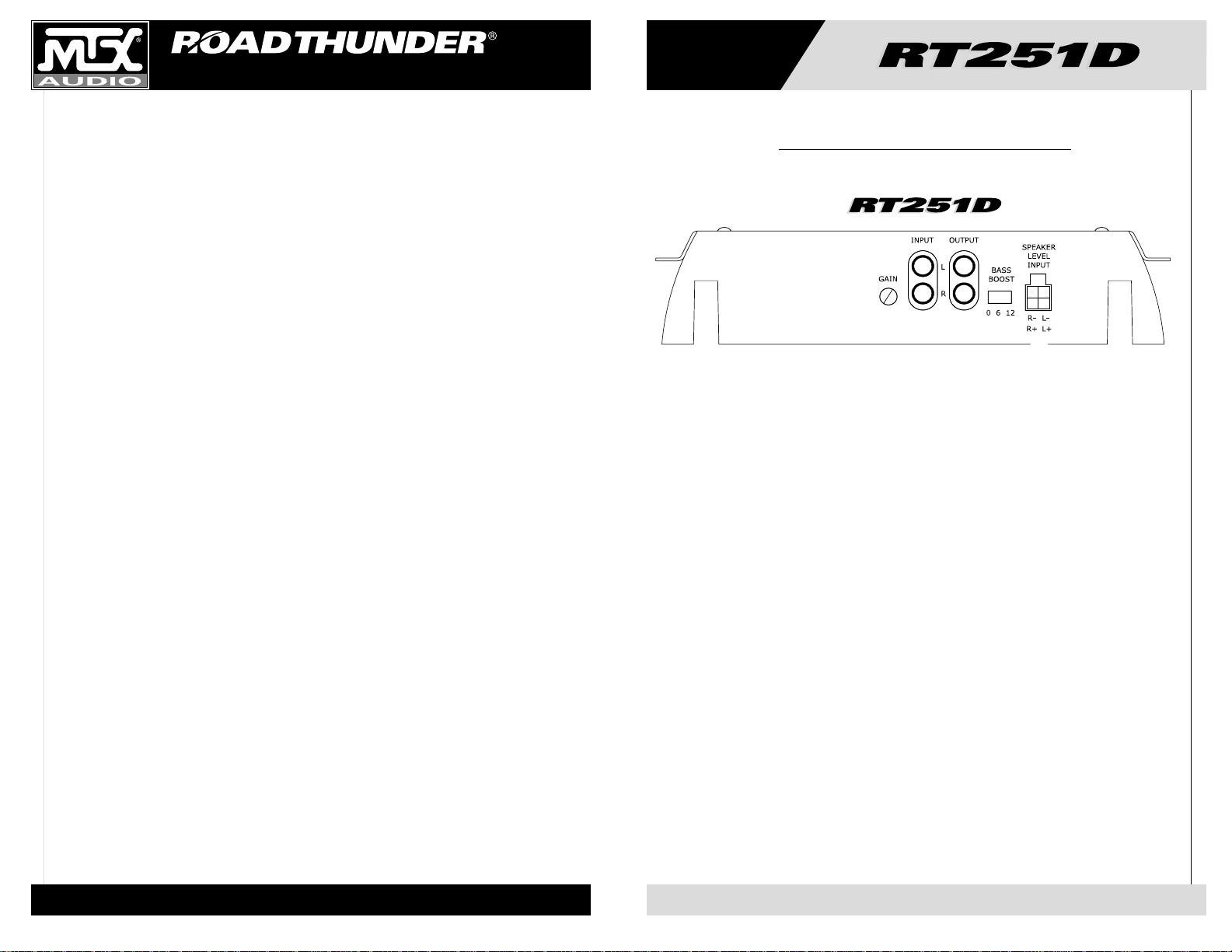
1. Gain Controls – These controls are used to match the input sensitivity of the amplifier to the particular
source unit that you are using. The controls are factory set to 1Vrms.
2. Bass Boost – This equalization circuit is used to enhance the low frequency response of the vehicle’s
interior. With up to 12dB of boost and centered at 40Hz, the Bass Boost can be adjusted to meet your own
personal taste.
3. RCA Input Jacks – RCA type input jacks for use with source units that have RCA or Line Level Outputs.
A source unit with a minimum output level of 200mV is required for proper operation. However, this input
will accept levels up to 8Vrms.
4. RCA Output Jacks –
These RCA outputs allow for a signal to be sent to other amplifiers in a daisy-chain con-
figuration.
5. Speaker Level Inputs – This input will allow the RT251D to operate from source units with speaker-level
outputs. Output speaker leads from the source unit should be tied directly to the wire harness provided
with the amplifier.
Wire harness color codes:
Grey / Black = Source unit right negative (-) White / Black = Source unit left negative (-)
Solid Grey = Source unit right positive (+) Solid White = Source unit left positive (+)
With the Smart-Engage™ auto-turn-on circuit, a remote turn-on wire is not necessary when connecting
the speaker-level input wire harness to a high powered source unit. The amplifier will automatically turn
on when music is received.
Input Panel Layout
❶
❹
❷
❸
❺
Page 4
AMPLIFIER OWNER’S MANUAL
6
7
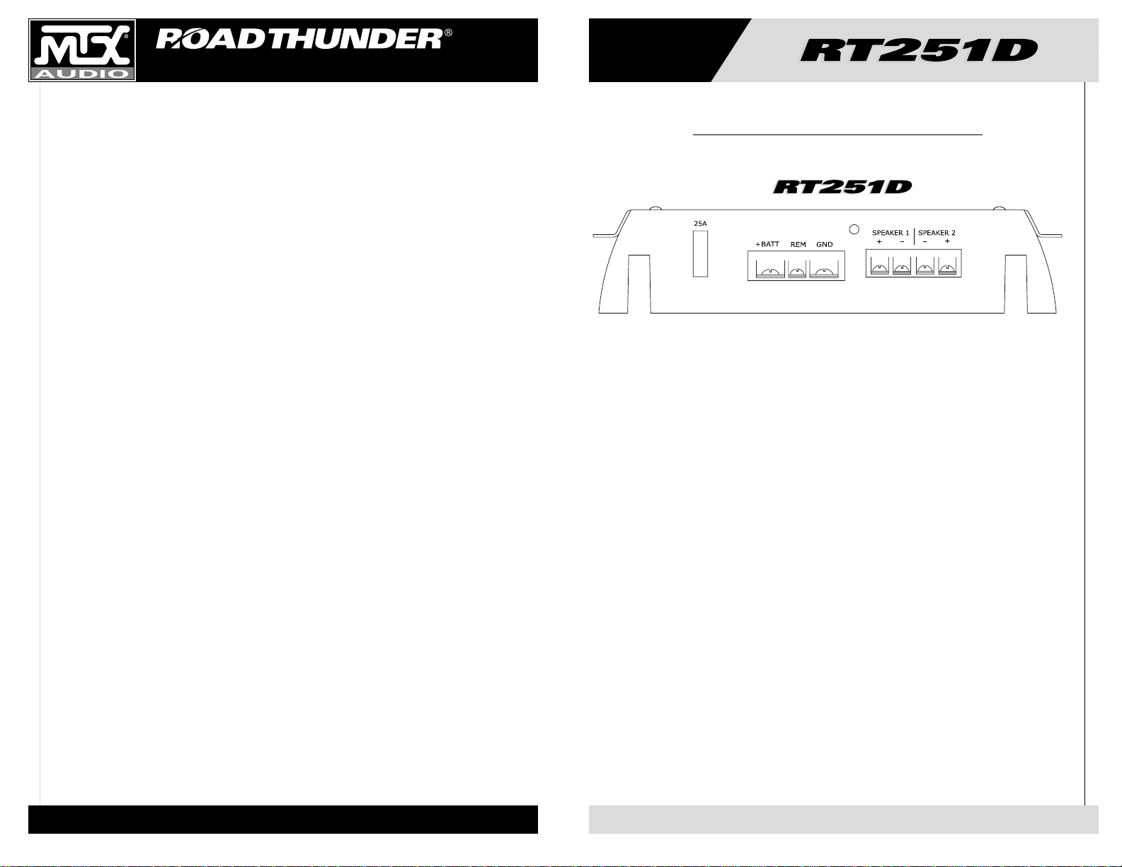
1. Fuses- For convenience, all amplifiers utilize ATC type fuses. For continued protection in the event that
a fuse blows, replace the fuse only with the same value.
Caution - The power fuses on the amp are for protecting the amp against overdrive. To protect the vehicle’s electrical system, an additional fuse is required within 18" of the battery on the 12V+ cable.
RT251D - 25A
2. Power Terminal –This is the main power input for the amplifier and must be connected directly to the
positive terminal of the car battery for the amplifier to operate properly. See the chart below for recommended cable sizes for each amplifier. Use caution when running this cable through the car. Try to avoid
the input RCA cables, antenna cabling, or other sensitive equipment as the large amount of current flowing through this cable can induce noise into your system. It is also very important to have a tight connection to ensure maximum performance.
RT251D - 6-8 Gauge
3. Ground Terminal –A good quality ground is required for your Road Thunder Amplifier to operate at peak
performance. A short length of cable the same gauge as your power cable should be used to attach the
ground terminal directly to the chassis of the car. Always scrape or sand any painted surfaces to expose
bare metal where the ground wire will attach.
4. Remote Terminal –All Road Thunder Amplifiers can be turned on by applying 12 volts to this terminal.
Typically this voltage is supplied by a wire from the source unit marked “remote” or “electric antenna”.
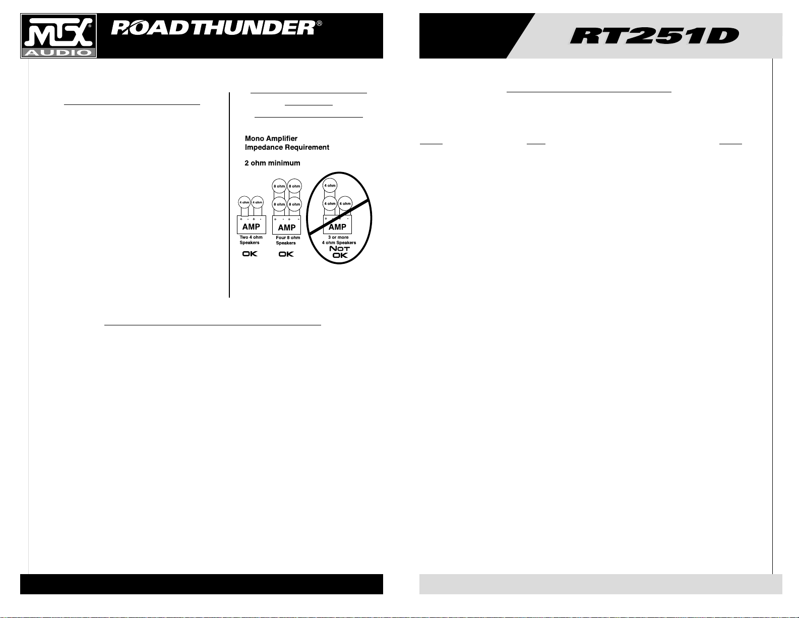
5. Speaker Terminals –As shown in the wiring diagrams, be sure to observe speaker polarity through the
system. Failing to wire the speakers in proper phase could result in a loss of bass response and/or poor overall sound quality. Caution: Road Thunder amplifiers are not recommended for loads below 2 ohms stereo.
6. Power LED – A lighted LED indicates that power has been applied to the amplifier. +12V from the battery
to the +BATT terminal and +12V from a switched ignition or remote lead from a head unit. An unlighted
LED indicates power has been removed or the amplifier has overheated. In the case of the overheat condition, the amplifier will turn back on after it cools down.
Output Panel Layout
❶
❷
❸
❹
❺
❻
Page 5
AMPLIFIER OWNER’S MANUAL
8
9
The following list of terms with their definitions is offered as
help in understanding the set-up and operation of your
amplifier.
1. Crossover (xover) - an electrical filter with high-pass or
low-pass characteristics that divides the frequency range
into playable bands for certain speakers. Subwoofers, midbass, midrange and tweeters are all designed to play different frequencies and should do so to avoid damage. The
xover point is where the playable frequencies cross from
one speaker to the next at -3dB below reference level.
2. Full-range - refers to signals which cover the entire audio
frequency span from 20Hz to 20kHz.
3. High-pass - simply put, this blocks lower frequencies
which damage smaller speakers, and passes the higher
frequencies for smaller speakers like the midrange and
tweeter.
4. Low-pass - you got it, this is the inverse of a high-pass. It
blocks higher frequencies and passes the playable lower
frequencies to the larger speakers, like subwoofers.
5. Impedance - the resistance to the flow of current in an
alternating current circuit (such as with music). Line level
circuits are typically a high impedance of several thousand
ohms, while speaker level circuits are usually a low impedance of a few ohms.
6. Line level - the type of signal produced at the outputs of
tape decks, CD tuners, preamplifiers, etc., with a typical
value of a volt or less in a high impedance circuit.
7. Speaker level - the type of output that is meant to drive
speakers. These signals are sometimes called high level
and are usually connected by two conductor speaker wires.
8. Signal - the signal of an audio system is what is heard
from the speakers. These signals may be high pass, low
pass or full-range.
We don’t have enough space for Electronics 101, so if you
have a good, bad or amusing question, please call us TOLL
FREE at 800-CALL MTX! (800-225-5689)
Adjusting the Gain
1. Turn the gain control on the amplifier all the way down.
2. Turn up the volume control on the source unit to
approximately
3
⁄4 of maximum.
3. Adjust the gain control on the amplifier until audible
distortion occurs.
4.
Adjust the gain control down until audible distortion
disappears.
5. The amplifier is now calibrated to the output of the
source unit.
Typical Speaker
Wiring
Configurations
Definitions of Common Terms
Read this if you wanna be a do-it-yourselfer - or give us a call at 800-CALL MTX.
Problem Cause Solution
No LED indication No +12V at remote connection Supply +12V to terminal
No +12V at Power connection Supply +12V to terminal
Insufficient ground connection Verify ground connection
Blown power fuse Replace fuse
LED on, no output Volume on head unit off Increase volume on head unit
Speaker connections not made Make speaker connections
Gain control on amplifier off Turn up gain
Signal processing units off Apply power to signal processor
All speakers blown Replace speakers
Output distorted Head unit volume set too high Lower head unit volume
Amplifier gain set too high Lower amplifier gain
Balance reversed Speakers wired L + R reversed Wire speakers with correct orientation
RCA inputs reversed Reverse RCA inputs
Some balance reversed Some Speakers wired L + R Wire speakers with correct orientation
reversed
Some RCA inputs reversed Reverse appropriate RCA inputs
Bass is boomy Bass Boost too high Lower setting
Bass is weak Bass Boost too low Raise setting
Speakers wired out Wire with correct phase
of phase
Not using MTX woofers Buy MTX woofers
Blowing fuses Excessive output levels Lower volume
Amplifier defective Return for service
Troubleshooting Guide
Page 6

AMPLIFIER OWNER’S MANUAL
10
11
Introduction
FELICITATIONS...
vous félicitant de votre achat d’un nouveau amplificateur MTX Audio Road
Thunder ! MTX a été depuis longtemps
un leader dans l’industrie d’enclos
mobiles et speakers, et nous sommes
arrivés à un nouveau sommet avec le
développement des nouveaux amplificateurs MTX Road Thunder. Vous n’auriez pas pu choisir d’amplificateur plus
fiable, plus puissant ou meilleur.
Nous fabriquons chaque amplificateur
en employant la Technologie Surface
Mount le plus récent et intelligent .
Quelques advantages du nouveau dessin sont
les perfectionnements aux propriétés
mécaniques et électriques de l’amplificateur.
Les mécanismes ISMT ont de substantiellement plus courtes longueurs internes et
externes. Cela réduit l’inductance et la
capacitance égarées, qui résulte en une
reproduction musicale plus pure et plus
exacte avec considérablement moins d’intervention du bruit. Le ISMT mounter produit des
cartes d’amplificateur avec plus petits et plus
légèrs composants qui sont plus résistants
aux vibrations inhérentes dans l’environnement automobile.
Nous voulons tout faire pour assurer que vous
obtenez la haute performance continue de
votre amplificateur MTX Road Thunder, donc
nous vous recommandons de l’avoir installé
professionellement par votre vendeur agréé.
COMMENT UTILISER CE MANUEL
Si vous installez cet amplificateur vousmême, nous vous recommandons de lire ce
manuel de la première à la dernière page
avant de l’installer. Familiarisez-vous avec les
caractéristiques et les détails des panneaux
entrée-sortie. Vérifiez que vous avez tout
l’équipement dont vous avez besoin. Puis
suivez les instructions d’installation point par
point qui se trouvent. Vous pouvez trouver
des échantillons des diagrammes d’installation sur le Web à notre site :
mtx.com
Si vous avez des questions, écrivez ou
téléphonez-nous à :
MTX Audio
4545 E. Baseline Rd.
Phoenix, AZ 85042
602-438-4545
800-CALL MTX
technical@mtx.com
mtx.com
FRANÇAIS
• Technologie Intelligente Surface Mount
• Source d’alimentation à découpage PWM MOSFET brevetée (5 598 325)
• Technologie d’adaptation Classe D
• Transformateur haute puissance
• Bobine superposée de forte puissance
• Dessin N-canal pur
• Double la puissance sous 2 ohms
• Circuit de protection informatisé temps réel
• Harnais métallique codifié par couleurs pour l’installation d’éntrée au niveau speaker
• Mise sous tension automatique Smart-Engage™ facilitant l’intégration avec les appareils sources
montés en usine
• Mise sous tension/hors tension acoustiquement transparente (c’est-à-dire sans bruit)
• Filtre passe-bas à fréquence de coupure de 85 Hz, 24dB/octave
• Amplificateur commutable Bass Boost @ 0, 6 ou 12dB centré sur 40 Hz
• Entrées bas niveau
• Sensibilité d’entrée réglable
• Connecteurs nickelés, d’un type bloc terminal à usage industriel
• Iso-Feet™ uniques, isolants en caoutchouc
Specifications
Caractéristiques
RT251D
RMS Power measured at 14.4 Volts DC:
100 Watts x 1 into a 4 Ohm load with less than 1% Thd+N
200 Watts x 1 into a 2 Ohm load with less than 1% Thd+N
Dynamic Power measured at 14.4 Volts DC:
125 Watts x 1 into a 4 Ohm load
250 Watts x 1 into a 2 Ohm load
Signal to Noise Ratio: ≥100dB A-Weighted
Frequency Response: 20Hz-85Hz
Maximum Input: 8Vrms
Bass Boost: Switchable Bass Boost 0, 6, or 12dB centered at 40Hz
Crossover: Fixed @ 85Hz, 18dB/octave low pass
Dimensions: Including Iso-Feet™
7.98" x 9.75" x 2.1" (20.3cm x 24.8cm x 5.3cm)
Page 7

AMPLIFIER OWNER’S MANUAL
12
13
1. Gain Control – Ces contrôles sont utilisés pour lier la sensibilité d’entrée de l’amplificateur à l’unité de
source particulier que vous utilitez. Les contrôles sont établis à l’usine à 1Vrms.
2. Bass Boost – Ce circuit d’équilibre se sert d’augmenter la réponse de basse fréquence de
l’intérieur du véhicule. Avec jusqu’à 12dB de boost et basé sur 40Hz, le Bass peut être réglé à votre goût.
3. RCA jacks d’entrée – RCA ou type de jacks d’entrée qui fonctionne les unités de source avec les sorties RCA ou Line Level. Une unité de source avec un niveau de sortie minimum de 200mV est nécessaire
pour bon fonctionnement. Cependant, ce jack d’entrée acceptera les niveaux jusqu’à 8Vrms.
4. RCA jacks de sortie – Ces sorties RCA permet un signal d’être envoyé aux autres amplificateurs dans
une configuration en série.
5. Entrées de niveau speaker – Cette entrée permettra à RT251D d’opérer d’unités de source avec sorties de niveau speaker. Les fils de sortie speaker de l’unité de source devraient attacher directement au
harnais métallique fourni avec l’amplificateur.
Les codes de couleur du harnais métallique:
Gris/Noir = Unités de source négatif droit(-) Blanc/Noir = Unités de source négatif gauche(-)
Gris solide = Unités de source positif droit(-) Blanc solide = Unités de source positif gauche(-)
Avec le circuit d’auto-allumage Smart-Engage™, un fil d’allumage n’est pas nécessaire pour attacher le
harnais métallique d’entrée niveau speaker à une unité de source de haute puissance. L’amplificateur
s’allumera automatiquement quand la musique sera reçue.
Agencement du panneau d’entrée
❶
❹
❷
❸
❺
Page 8

AMPLIFIER OWNER’S MANUAL
14
15
1. Fusibles - À titre pratique, tous les amplis utilisent des fusibles du type ATC. Pour une protection continue en cas de claquage du fusible, remplacez-le par un fusible de même calibre uniquement.
Attention - Les fusibles d’alimentation de l’ampli servent à protéger l’ampli contre une sur-utilisation. Pour
protéger le système électrique de votre véhicule, un fusible supplémentaire est nécessaire à moins de 50
cm de la batterie sur le câble de 12 V+.
RT251D – 25A
2. Terminal du pouvoir – C’est l’entrée du pouvoir principal pour l’amplificateur et il doit être connecté
directement au terminal positif de la pile de la voiture pour que l’amplificateur marche correctement.
Voyez le tableau dessous pour les tailles de câble recommandées pour chaque amplificateur. Soyez prudent quand vous installez ce câble dans la voiture. C’est aussi très important d’avoir une connection serrée pour assurer la performance maximale.
RT251D – 6-8 calibre
3. Connecteur de masse – Une mise à la masse correcte est nécessaire pour que votre ampli Road
Thunder fonctionne de manière optimale. Un câble court du même calibre que votre câble d’alimentation
doit servir à attacher la borne de terre directement sur le châssis de la voiture. Grattez ou poncez toujours
une surface peinte de la voiture pour exposer le métal nu au point de branchement du fil de masse.
4. Borne à distance – Tous les amplis Road Thunder sont mis en marche en appliquant 12 V à cette borne.
En général, cette tension est fournie par un câble issu de l’unité source marqué « remote » (à distance) ou
« electric antenna » (antenne électrique).
5. Bornes de haut-parleurs –Comme indiqué dans les schémas de câblage, respectez la polarité des hautparleurs à travers le système sous peine d’entraîner une perte de réponse des basses et/ou une qualité
sonore globalement médiocre. Attention : Les amplis Road Thunder ne sont pas recommandés pour des
charges inférieures à 2 Ohms (stéréo) ou 4 Ohms (possibilité d’écoute).
6. LED d’alimentation - L ’allumage de la LED indique que l’ampli est alimenté (+12 V de la batterie à la borne
+BATT et + 12 V d’une alimentation commutée ou d’un fil distant d’une unité de tête). La LED éteinte indique
que l’alimentation a été coupée ou que l’ampli a surchauffé. En présence d’une surchauffe, l’ampli se
remettra en marche dès qu’il aura refroidi.
Branchements sur connecteur de sortie
❶
❷
❸
❹
❺
❻
Page 9

AMPLIFIER OWNER’S MANUAL
16
17
La liste des termes suivants et leur définition permettra de
vous aider à comprendre l’installation et le fonctionnement de votre ampli. (vous d’vez piger c’qu’on dit!)
1. Filtre actif - filtre électrique passe-haut ou passe-bas
qui divise la plage de fréquence en bandes compatibles
avec certains haut-parleurs. Les subwoofers, les hautparleurs pour fréquences moyennes et les tweeters ont
tous été conçus pour utiliser des fréquences différentes
et doivent se limiter à ces fréquences pour empêcher tout
endommagement. Le point de recoupement correspond
au point où les fréquences utilisables passent d’un hautparleur à un autre à - 3dB en dessous du niveau de
référence.
2. Large bande - désigne les signaux qui couvrent
l’ensemble de la gamme de fréquences sonores (de 20 Hz
à 20 kHz).
3. Passe-haut - en termes clairs, ce filtre bloque les basses fréquences qui peuvent endommager les petits hautparleurs et laisse passer les hautes fréquences pour les
petits haut-parleurs tels que les médiums et les tweeters.
4. Passe-bas - Gagné ! c’est le contraire de passe-haut !
Ce filtre bloque les hautes fréquences et laisse passer les
basses fréquences utilisables par les haut-parleurs plus
importants, comme les subwoofers
5. Impédance - C’est la résistance au courant dans un circuit de courant alternatif (circuits musicaux, notamment).
Les circuits de niveau de ligne affichent généralement
une impédance élevée de plusieurs milliers d’ohms, tandis que les circuits de niveau haut-parleur affichent
généralement une impédance basse de quelques ohms.
6. Niveau de ligne - type de signal produit aux sorties des
platines magnétophone, des tuners, des lecteurs CD, des
pré-amplis, etc., avec une valeur typique d’un volt maximum dans un circuit à impédance élevée. (Récemment
toutefois, certains fabricants de sources se sont ravisés
et se sont mis à produire des unités haute tension
affichant des sorties pouvant atteindre 8 V. On en redemande !!) Parfois appelés signaux de bas niveau, ils sont
généralement reliés via des câbles RCA.
7. Niveau haut-parleur - type de sortie nécessaire pour
activer les haut-parleurs. Ces signaux sont parfois
appelés signaux de haut niveau et sont généralement
conduits par deux fils de haut-parleur.
8. Signal - signal d’un système sonore issu des haut-parleurs. Ces signaux peuvent être des signaux passe-haut,
passe-bas ou large bande.
Comme nous n’avons pas assez de place pour vous faire
un cours d’initiation à l’électronique, si vous avez une
question sympa, méchante ou amusante, appelez-nous au
01 42 28 72 52.
Réglage du volume
1. Baissez complètement le gain sur l’ampli.
2. Montez le volume à environ 3⁄4 du maximum
sur la source.
3. Montez le gain du canal de droite sur l’ampli,
jusqu’à ce qu’une distorsion audible se produise.
4. Baissez le gain du canal de droite sur l’ampli,
jusqu’à ce que la distorsion audible disparaisse.
5. Réglez le gain du canal de gauche sur la
même position.
6. L’ampli est désormais étalonné par rapport à
la source.
Haut-parleur standard
Branchements
Définition des terms courants
Problème Cause Solution
La LED reste éteinte Pas de + 12 V sur le REMOTE Alimentez la borne en + 12 V
Pas de + 12 V à l’alimentation Brancher l’alimentation en + 12 V
Branchement de la masse insuffisant Vérifiez le branchement à la masse
Fusible d’alimentation claqué Remplacez le fusible
La LED est allumée, mais Volume activé, source désactivée Montez le volume sur la source
pas de sortie Branchement des haut-parleurs non établis Etablissez les branchements
des haut-parleurs
Commande de volume désactivée sur l’ampli Montez le volume
Pré ampli désactivé Alimentez le processeur de signaux
Tous les haut-parleurs ont grillé Remplacez les haut-parleurs
Sortie perturbée Volume de la source trop fort Baissez le volume de la source
Gain de l’ampli trop fort Baissez le gain de l’amplifi
Balance inversée Certains fils G et D des haut-parleurs sont Branchez les haut-parleurs
inversés en respectant polarité
Certaines entrées RCA sont inversées Inversez les entrées RCA
Balance partiellement inversée Certains fils G et D des haut-parleurs sont Branchez les haut-parleurs
inversés en respectant polarité
Certaines entrées RCA inversées Inversez les entrées RCA appropriées
Basses restituées trop fortes Bass Boost trop fort Baissez le réglage
Basses restituées trop faibles Bass Boost trop faible Montez le réglage
Haut-parleurs branchés déphasés Branchez correctement la phase
VOUS N’UTILISEZ PAS DE WOOFERS MTX Achetez des woofers MTX
Fusibles qui claquent Niveaux de sortie excessifs Baissez le volume
Ampli défectueux Renvoyez le pour réparation
Guide de dépannage
Page 10

AMPLIFIER OWNER’S MANUAL
18
19
CONGRATULACIONES
Por su compra del nuevo Amplificador
Road Thunder MTX Audio! MTX viene
siendo el líder en la industria de gabinetes de altoparlantes móviles y altoparlantes. Hemos alcanzado nuevos niveles
con el desarrollo de los nuevos amplificadores Road Thunder MTX. Usted no
pudo haber elegido un amplificador más
seguro, potente y de mejor funcionamiento.
Cada amplificador esta fabricado usando la "T ecnología de Montaje Inteligente
Para Cualquier Superficie" más reciente.
Alguna de las ventajas del nuevo diseño
incluyen la mejora significativa de las
propiedades electrónicas y mecánicas del
amplificador. Los dispositivos ISMT se caracterizan por tener guías internas y externas
mucho más cortas. Esto reduce pérdida en
capacitores e inductores, lo cual resulta en
una reproducción musical mucho más fiel,
con significativa reducción de interferencias.
El armador ISMT, produce plaquetas de
amplificación, con componentes más livianos
y pequeños, produciendo un circuito compacto, que se hace mas resistente a las vibraciones típicas, a que es sometido en el medio
ambiente automovilístico.
Como queremos asegurar que usted reciba
un alto rendimiento continuo de su amplificador Road Thunder MTX, recomendamos
que lo haga instalar profesionalmente por su
representante MTX autorizado.
COMO USAR ESTE MANUAL
Si está instalando usted mismo el amplificador, le recomendamos que lea el manual
de principio a fin antes de comenzar la instalación. Familiarícese con las características
y detalles de los paneles de entrada (Input) y
salida (Output). Asegúrese que tiene todo el
equipo necesario. Luego siga paso a paso
las instrucciones de instalación. Puede
encontrar diagramas simples de instalación,
en nuestro sitio de Internet:
mtx.com
Si tiene alguna pregunta, escriba o llámenos a:
MTX Audio
4545 East Baseline Road
Phoenix, AZ 85042
602-438-4545
800-CALL MTX
technical@mtx.com
mtx.com
Características
Introducción
ESPAÑOL
RT251D
RMS Power measured at 14.4 Volts DC:
100 Watts x 1 into a 4 Ohm load with less than 1% Thd+N
200 Watts x 1 into a 2 Ohm load with less than 1% Thd+N
Dynamic Power measured at 14.4 Volts DC:
125 Watts x 1 into a 4 Ohm load
250 Watts x 1 into a 2 Ohm load
Signal to Noise Ratio: ≥100dB A-Weighted
Frequency Response: 20Hz-85Hz
Maximum Input: 8Vrms
Bass Boost: Switchable Bass Boost 0, 6, or 12dB centered at 40Hz
Crossover: Fixed @ 85Hz, 18dB/octave low pass
Dimensions: Including Iso-Feet™
7.98" x 9.75" x 2.1" (20.3cm x 24.8cm x 5.3cm)
Specifications
• Tecnología de Montaje Inteligente para Cualquier Superficie
• Fuente de energía de transferencia regulada PWM MOSFET patentada (Patente #5,598,325)
• Tecnología Adaptada Clase D
• Transformadores de alto poder
• Inductor apilado de alta potencia
• Diseño Puro de Canal-N
• Duplica la potencia a 2 ohms
• Circuito de protección computarizado de tiempo real
• Paquete de cables numerados con código de colores para instalación del parlante RT251D de salida
nivelada
• Encendido automático Smart-Engage™ que permite fácil integración con las unidades de fábrica
• Encendido y apagado sin altibajos acústicos (es decir, sin ruido)
• Crossover de pasabajas, 85 Hz, pasabajas de 24dB/octava
• Refuerzo de bajo Bass Boost con interruptor @ 0, 6 ó 12dB centrado en 40 Hz
• Entradas de nivel bajo
• Sensibilidad de entrada izquierda y derecha individualmente ajustable
• Conectores de trabajo pesado de la terminal tipo bloque, chapados en oro
• Iso-Feet™, Unico, de caucho, de alta aislación
Page 11

AMPLIFIER OWNER’S MANUAL
20
21
1. Control de Ganancia – Estos controles se usan para igualar la sensibilidad de entrada del amplificador
con la unidad que usted esta usando. Los controles vienen ajustados de fábrica para 1Vrms.
2. Bass Boost – Este circuito de estabilización se usa para aumentar la respuesta de baja frecuencia del
interior del vehículo. De hasta 12dB de empuje y centrado a 40Hz, el Estabilizador de Bajos puede ser
ajustado para satisfacer su preferencia personal.
4. Jacks de Entrada RCA – Jacks de entrada tipo RCA para usar con unidades que tienen RCA o Salidas
de Línea Nivelada. Para un funcionamiento correcto se requiere una unidad con un nivel de salida mínimo de 200mV. Sin embargo, esta entrada acepta niveles de hasta 8Vrms.
5. Jacks de Salida RCA – Estas salidas RCA permiten enviar una señal a otros amplificadores en una configuración en cadena. Los jacks de salida RCA también permiten que se pueda controlar el nivel de múltiples amplificadores de bajos, usando un EBC (Control de Bajo Electrónico.)
6. Entrada Nivelada – Esta entrada permitirá al RT251D operar desde unidades con parlantes de salida
nivelada. Las guías de salida del parlante que provienen de la unidad deben ser conectadas directamente
al paquete de cable que viene con el amplificador.
Código de color del paquete de cable:
Gris / Negro = Derecha negativa (-) de la unidad Blanco / Negro = Izquierda negativa
(-) de la unidad
Gris Sólido = Derecha positiva (+) de la unidad Blanco Sólido = Izquierda positiva
(+) de la unidad
Con el circuito de encendido automático Smart-Engage™, no es necesario usar un cable de encendido
remoto, cuando se conecta el paquete de cables del parlante de entrada nivelada a una unidad de alta
potencia. El amplificador se encenderá automáticamente al recibir la música.
Diagrama del panel de entrada
❶
❹
❷
❸
❺
Page 12

AMPLIFIER OWNER’S MANUAL
22
23
1. Fusibles - Para mayor comodidad, todos los amplificadores utilizan fusibles de tipo ATC. Para obtener
protección continua en caso de que se funda un fusible, reemplace el fusible dañado SOLAMENTE por
otro similar.
Precaución. Los fusibles del amplificador son para protección contra una sobrecarga. Para proteger el sistema
eléctrico de su vehículo se necesita un fusible adicional colocado a una distancia no mayor que 18" (45 cm) de
la salida de la batería. Consulte el diagrama de instalación de la página 11.
RT251D – 25 Amp
2. Terminal de poder –Esta es la principal entrada de poder del amplificador y se debe conectar directa-
mente en la terminal positiva de la batería del automóvil para que el amplificador funcione adecuadamente. Consulte la siguiente tabla para ver el tamaño de cable recomendado para cada amplificador.
Tenga cuidado al extender este cable en el auto. Trate de evitar los cables de entrada RCA, las conexiones
de la antena ycualquier otro equipo sensible ya que la gran cantidad de corriente que fluye a través de
este cable puede inducir ruido hacia su sistema. También es muy importante que las conexiones estén
bien aseguradas para obtener un rendimiento máximo.
RT251D – Escala 6-8
3. Terminal a tierra – Para que su amplificador Road Thunder funcione a su máximo rendimiento se
requiere una conexión a tierra de buena calidad. Se debe utilizar un tramo corto de cable del mismo calibre que su cable de poder para conectar la tereminal a tierra directamente en l chasis del auto. Siempre
raspe o lije cualquier superficie pintada para exponer el metal en el área donde va a conectar el cable de
conexión a tierra.
4. Terminal remoto –Todos los amplificadores Road Thunder se pueden encender aplicando 12 voltios a
este terminal. Típicamente este voltaje lo suministra un cable desde la unidad generadora, que está marcado como "remoto" o "antena eléctrica".
5. Terminales de los altavoces –Como se muestra en los diagramas de conexión, asegúrese de seguir la
polaridad de los altavoces en todo el sistema. La conexión de los altavoces en la fase errónea podría dar
como resultado la pérdida de respuesta de los bajos y/o una deficiente calidad del sonido en general.
Precaución: no se recomiendan los amplificadores Road Thunder para cargas menores de 2 omhios en
estéreo o 4 ohmios puenteadas.
6. Luz de encendido –El amplificador se encuentra encendido cuando el indicador (LED) está iluminado.
Un LED apagado indica que el amplificador se sobrecalentó o que el amplificador ha sido apagado. En ell
caso de calentamiento excesivo, el amplificador se encendera de nuevo después de enfriarse.
Diagrama de la placa de salida
❶
❷
❸
❹
❺
❻
Page 13

AMPLIFIER OWNER’S MANUAL
24
25
Le presentamos la siguiente lista de términos y sus definiciones para ayudarle a entender la instalación y funcionamiento de su amplificador.
1. Crossover (xover)- un filtro eléctrico con características de paso alto y paso bajo que divide la variación de la
frecuencia en bandas reproducibles para ciertas bocinas.
Todos los bajos (subwoofers), bajos medios, bocinas de
media frecuencia (midrange), de alta frecuencia (tweeters), están diseñados para reproducir diferentes frecuencias y deben hacerlo para evitar dañarse. El punto de
crossover es donde las frecuencias reproducibles se
cruzan de una bocina a la siguiente a -3dB por debajo del
nivel de referencia.
2. Frecuencia completa- se refiere a las señales que
cubren toda la variación de frecuencias audibles desde
20Hz hasta 20kHz.
3. Paso alto- este paso bloquea las frecuencias bajas que
dañan las bocinas más pequeñas, y pasa las frecuencias
altas a las bocinas más pequeñas como las de mid range
y los tweeters.
4. Paso bajo- esto es lo contrario al paso alto. Este
paso bloquea las frecuencias altas y pasa las frecuencias
bajas reproducibles a las bocinas más grandes, como
los subwoofers.
5. Impedancia- es la resistencia al flujo de corriente en un
circuito de corriente alterna (como en el caso de la música). Los circuitos de nivel de linea tienen una impedancia
alta de varios miles de ohms, mientras que los circuitos de
nivel de bocina tienen generalmente una impedancia baja
de pocos ohms.
6. Nivel de linea- el tipo de señal que seproduce en las
salidas de unidades de cinta, sintonizadores de CD, preamplificadores, etc., con un valor típico de un volt o menos
en un circuito de impedancia alta. (Sin embargo, recientemente, algunas compañías estéreos produjeron unidades
con salidas de hasta 8 volts. (¡Qué maravilla!) Algunas
veces se les llama señales de nivel bajo, y normalmente
están se conectan por medio de cables RCA.
7. Nivel de bocina- el tipo de salida que está diseñado
para excitar las bocinas. Estas señales algunas veces se
llaman de alto nivel y generalmente se conectan con dos
cables conductores para bocinas.
8. Señal- la señal de un sistema de sonido es lo que se
escucha en las bocinas. Estas señales pueden ser de
paso alto, de paso bajo o de frecuencia completa.
No tenemos suficiente espacio para el curso de Electrónica 101,
de manera que, si tiene una pregunta buena, mala o divertida, por
favor llámenos al teléfono (602) 438 4545 ¡SIN CARGO PARA
USTED!
Ajuste de los controles
de ganancia
1. Ajuste el control de ganancia del amplificador hasta el
valor mínimo.
2. Gire el control del volumen de su estéreo hasta aproximadamente
3
⁄4 del máximo.
3. Ajuste el control de ganancia del amplificador hasta
que se presente una distorsión audible
4. Disminuya el control de ganancia hasta que la distorsión no sea audible.
5. Ahora el amplificador está calibrado con su estéreo.
Typical Speaker
Wiring
Configurations
Definición de Términos Comunes
Problema Causa Solución
No hay indicación de LED Menos de +12V en la conexión remota Suministre +12V a la terminal
Menos de +12V en la conexión a la Suministre +12V a la terminal
alimentación
Conexion insuficiente a tierra Verifique la conexión a tierra
Fusible fundido Cambie el fusible
LED encendido, no hay salida Volumen en la, unidad principal. Al minimo Aumente el volumen en la
unidad principal
No hay conexiones con las bocinas Conecte las bocinas
Control de ganancia en el amplificador Aumente el control de ganancia
al mínimo
Unidades de procesamiento de señales Energice el procesador de señales
apagadas
Todas las bocinas dañadas Cambie las bocinas
Salida distorsionada Volumen de la unidad princ. muy alto Disminuya el volumen de la
unidad principal
Amplificación muy alta Disminuya la ganancia del amplificador
Balance invertido Las bocinas se conectaron al revés Conecte las bocinas con la
polaridad correcta
Entradas RCA al revés Invierta las entradas RCA
Parte del Balance invertido Algunos cables de las bocinas estan cruzados Conecte las bocinas con la
orientación correcta
Algunas de las entradas RCA están al revés Invierta las entradas RCA a la
posición correcta
Los bajos están muy fuertes Bass Boost está demasiado alto Disminuya el ajuste
Los bajos están muy débiles Bass Boost está demasiado bajo Eleve el ajuste
Bocinas conectadas fuera de fase Conecte con la fase correcta
No esta usando woofers MTX Compre woofers MTX
Los fusibles se están fundiendo Niveles de salida excesivos Disminuya el volumen
Amplificador defectuoso Devuelva la unidad para darle servicio
Guía para la solución de problemas
Page 14

AMPLIFIER OWNER’S MANUAL
26
27
Introduction
WIR GRATULIEREN!
Wir gratulieren Ihnen zum Kauf
des neuen MTX Audio Road ThunderVerstärkers! MTX ist schon seit langem
führend auf dem Gebiet von
Mobilgeräten und Lautsprechern, und
mit der Entwicklung des neuen MTX
Road Thunder setzen wir diese
Tradition fort. Sie hätten kaum einen
verlässlicheren und leistungsstärkeren
Verstärker wählen können.
Alle unsere Verstärker haben die
inteligente Außenmontagetechnologie. Einige Vorteile der neuen Bauart
sind die Verbesserungen der elektron-
ischen und mechanischen
Eigenschaften des Verstärkers. ISMT-Geräte
haben wesentlich kürzere interne und
externe Leitungslängen, was die
Streukapazitanz und Induktivität herabsetzt
und Ihnen eine reinere und musikalisch
genauere Wiedergabe mit wesentlich
weniger Lärmstörung beschert. Die ISMTHalterung erlaubt Verstärker mit kleineren
und leichteren Bestandteilen, die mehr
beständig sind gegen Vibrationen, wie man
sie im Autoinnern vorfindet.
Wir wollen sicherstellen, dass Sie aus Ihrem
MTX Road Thunder immer die
Höchstleistung herausholen und empfehlen
deshalb, den Einbau von einem autorisierten
MTX-Vertreiber vornehmen zu lassen.
ZUR VERWENDUNG DIESES HANDBUCHS
Falls Sie diesen Verstärker selbst einbauen,
empfehlen wir Ihnen, das Handbuch vor dem
Einbau von Anfang bis zum Ende durchzulesen. Machen Sie sich vertraut mit allen
Details der Eingangssignal- und
Ausgangssignalbedienung. Versichern Sie
sich, dass Sie alle benötigte Ausrüstung
haben und folgen Sie dann den schrittweisen
Einbauinstruktionen. Beispiele von
Einbaudiagrammen finden Sie auf unserer
Webseite.
mtx.com
Falls Sie Fragen haben, schreiben Sie uns
oder rufen Sie uns an wie folgt:
MTX Audio
4545 E. baseline Rd.
Phoenix, AZ 85042
602-438-4545
800-CALL MTX
technical@mtx.com
mtx.com
GERMANIC
• Intelligente Außenmontagetechnologie
•
Patentiertes PWM MOSFET-Schaltnetzteil (Nr. 5,598,325)
• Anpassungsfähige Class-D Technologie
•
Verwendung von Hochleistungstransformatoren
•
Übereinander angeordneter Hochleistungsinduktor
• Reiner N-Kanal-Design
•
Verdopplung der Leistung beim Anschluss an 2 Ohm
•
Realtime-Computer-Schutzschaltung
• Farbkodiertes Drahtgeschirr zum Eingangseinbau auf Lautsprecherniveau auf dem RT251D
• Smart-Engage™ - automatische Einschaltfunktion zur leichten Integration mit Steuergerät (Head Unit)
• Akustisch nahtloses Ein-/Ausschalten (rauschfrei)
• Tiefpass-Frequenzweiche, 85 Hz, 24dB/Oktave Tiefpass
• Schaltbarer Bass Boost @ 0, 6 oder 12dB um 40 Hz zentriert
• Kleinsignalausgänge
•
Einstellbare Eingangsempfindlichkeit
• Nickel-beschichtet, strapazierfähige Klemmenverbinder in Blockform
• Einzigartiges mit Gummi isoliertes Iso-Feet™
Technische Information
Specifications
RT251D
RMS Power measured at 14.4 Volts DC:
100 Watts x 1 into a 4 Ohm load with less than 1% Thd+N
200 Watts x 1 into a 2 Ohm load with less than 1% Thd+N
Dynamic Power measured at 14.4 Volts DC:
125 Watts x 1 into a 4 Ohm load
250 Watts x 1 into a 2 Ohm load
Signal to Noise Ratio: ≥100dB A-Weighted
Frequency Response: 20Hz-85Hz
Maximum Input: 8Vrms
Bass Boost: Switchable Bass Boost 0, 6, or 12dB centered at 40Hz
Crossover: Fixed @ 85Hz, 18dB/octave low pass
Dimensions: Including Iso-Feet™
7.98" x 9.75" x 2.1" (20.3cm x 24.8cm x 5.3cm)
Page 15

AMPLIFIER OWNER’S MANUAL
28
29
1. Verstärkungsregelung – Diese Kontrollen werden eingesetzt, um die Eingangsempfindlichkeit des
Verstärkers an das verwendete Quellgerät anzupassen. Die Kontrollen sind von der Fabrik auf 1Vrms voreingestellt.
2. Bass Boost – Dieser Entzerrungsschaltkreis wird verwendet, um die Niedrigfrequenzwirkung des
Innenraums des Fahrzeugs zu erhöhen. Mit bis zu 12dB Verstärkung und zentriert auf 40 Mz, kann der Bass
Boost nach Geschmak eingestellt werden.
4. RCA Eingangsbuchsen – RCA Eingangsbuchsen zum Gebrauch mit Quellgeräten mit RCA oder
Linienpegel-Ausgangsignale. Zum richtigen Betrieb ist ein Mindestausgangspegel von 200mV erforderlich. Dieser Eingang akzeptiert aber Pegel bis zu 8Vrms.
5. RCA-Ausgangsbuchsen – Die RCA Ausgangsbuchsen erlauben es, ein Signal an andere aufeinadergereihte Verstärker zu senden. Die RCA Ausgänge erlauben auch eine Pegelkontrolle mehrerer
Bassverstärker unter Verwendung eines EBC.
6. Lautsprecherpegeleingänge – Dieser Eingang erlaubt den Betrieb des Road Thunder 425D und 6500D
von Quellgeräten mit Lautsprecherpegelausgängen. Ausgangslautsprecherleitungen vom Quellgerät sollten direkt an das mit dem Verstärker mitgelieferte Drahtgeschirr angeschlossen werden.
Drahtgeschirrfarbcode:
Grau/schwarz = Quellgeräte rechts negativ (-) Weiß/schwarz = Quellgeräte links negativ (-)
Dunkelgrau = Quellgeräte rechts positiv (+) Weiß = Quellgeräte rechts links positiv (+)
Mit dem Smart-Engage™ Selbstanschaltkreis ist ein entfernter Anschaltdraht nicht notwendig, wenn man
das Drahtgeschirr des Lautsprecherpegeleingangs an ein leistungsfähiges Quellgerät anschließt. Der
Verstärker schaltet sich bei Musikempfang automatisch ein.
Eingangskonsolen-Layout
❶
❹
❷
❸
❺
Page 16

AMPLIFIER OWNER’S MANUAL
30
31
1. Sicherung - Alle Verstärker verwenden ATC-Sicherungen. Durchgebrannte Sicherungen dürfen zu
Ihrem Schutz nur durch gleiche Sicherungen mit demselben Wert ersetzt werden.
Vorsicht - Die Sicherungen am Verstärker dienen zum Schutz des Verstärkers gegen Überlastung. Zum
Schutz des elektrischen Systems des Fahrzeugs ist eine zusätzliche Sicherung am 12V+ Kabel maximal 50
cm von der Batterie entfernt erforderlich.
RT251D – 25A
2. Power-Anschluß – Dieser Anschluß ist der Hauptstromeingang für den Verstärker und muß direkt an
den Batteriepluspol angeschlossen werden, damit der Verstärker sachgemäß funktionieren kann. Siehe
nachstehende Liste für empfohlene Kabelstärken für jeden Verstärker. Seien Sie beim Verlegen des
Kabels im Auto äußerst vorsichtig. Vermeiden Sie Kontakt mit den Eingangs-RCA-Kabeln, Antennenkabeln
oder anderen empfindlichen Geräten, da die große Menge Strom durch dieses Kabel Systemstörungen
verursachen kann. erten MTX Fachhändler oder Vertrieb wenden.
RT251D – Kabeldicke 6-8
3. Masseanschluß – Eine sehr gute Masseverbindung ist für eine Spitzenleisterwarten. Das "Certified
Performance Certificate" zeigt Ihnen eindeutig, wie Ihr Verstärker nicht nur alle Leistungswerte erzielt,
sondern diese oft sogar überschreitet.
4. Remote-Anschluß – Alle Road Thunder Verstärker werden eingeschaltet, indem 12 V an diesen
Anschluß angelegt werden. Die Spannung wird normalerweise über einen Draht vom Eingangsgerät zugeführt, der mit "Remote" oder "Elektrische Antenne" gekennzeichnet ist.
5. Lautsprecheranschlüsse – Achten Sie auf die Polarität der Lautsprecher durch das System (siehe
Verdrahtungspläne). Wenn die Lautsprecher nicht richtigphasig angeschlossen werden, können
Baßansprechungsverlust und/oder allgemein schlechte Soundqualität die Folge sein. Vorsicht: Road
Thunder Verstärker sind nicht für Belastungen unter 2 Ohm Stereo oder 4 Ohm überbrückt geeignet.
6. Power-LED - Eine leuchtende LED zeigt an, dass die Verstärkerspannung eingeschaltet ist. +12V von der
Batterie zum +BATT-Anschluss und +12V von einer geschalteten Zündung oder einem Remotekabel von
einem Stereosystem. Eine nicht leuchtende LED zeigt an, dass die Spannung entfernt wurde oder der
Verstärker überhitzt ist. Bei einer Überhitzung schaltet sich der Verstärker nach der Abkühlung wieder ein.
Ausgangskarte - Abbildung
❶
❷
❸
❹
❺
❻
Page 17

AMPLIFIER OWNER’S MANUAL
32
33
Die nachfolgende Liste von Ausdrücken mit den jeweiligen Definitionen soll zur Unterstützung bei Installation
und Betrieb Ihres Verstärkers dienen.
1. Frequenzweiche (xover)- Ein elektrischer Filter mit
Hochpaß- oder Tiefpaßfunktionen, der den
Frequenzbereich für bestimmte Lautsprecher unterteilt.
Subwoofer, Midbass, Mitteltöner und Hochtöner sind
alle absichtlich für unterschiedliche Frequenzen konzipiert. Der “xover”-Punkt ist der Punkt, an dem sich die
einzelnen Frequenzen von einem Lautsprecher zum
nächsten bei -3dB unterhalb des Referenzpegels überschneiden.
2. Vollbereich -Bezieht sich auf Signale, die die gesamte
Audiowobbelbandbreite von 20Hz bis 20kHz abdecken.
3. Hochpaß- Einfach ausgedrückt blockiert der
Hochpaß niedrigere Frequenzen, die kleine
Lautsprecher beschädigen können, und läßt die
höheren Frequenzen bei kleineren Lautsprechern (z.B.
Mittel- und Hochtöner) durch.
4. Tiefpaß-Der Tiefpaß blockiert höhere Frequenzen und
läßt die niedrigeren Frequenzen bei größeren
Lautsprechern (z.B. Subwoofer) durch.
5. Impedanz- Widerstand zum Stromfluß in einem
Wechselstromkreis (wie bei Musik). Line-LevelSchaltungen besitzen normalerweise eine hohe
Impedanz mit mehreren Tausend Ohm, während
Lautsprecherpegelschaltungen normalerweise über
eine niedrige Impedanz mit nur wenigen Ohm verfügen.
6. Line-Level- Signaltyp der Ausgänge von
Kassettendecks, CD-Playern, Vorverstärkern usw., normalerweise mit einem Wert von < 1 V in einem
Schaltkreis mit hoher Impedanz. Diese Signale werden
manchmal Low-Level-Signale genannt und üblicherweise mit RCA-Kabel angeschlossen.
7. Lautsprecherpegel- Der Ausgabetyp, der
Lautsprecher steuern soll. Dieses Signale werden
manchmal mit “High-Level” bezeichnet und üblicherweise mit zweipoligen Lautsprecherkabeln
angeschlossen.
Einstellen der
Verstärkungsregler
1. Drehen Sie die Verstärkungsregler auf dem
Verstärker ganz aus.
2. Drehen Sie den Lautstärkeregler auf dem
Eingangsgerät auf ca.
3
⁄4 des Maximums.
3. Stellen Sie den Verstärkungsregler des rechten
Kanals auf dem Verstärker ein, bis eine
Verzerrung hörbar wird.
4. Stellen Sie den Regler des rechten Kanals ein,
bis die Verzerrung nicht mehr hörbar ist.
5. Stellen Sie den Verstärkungsregler des linken
Kanals auf dieselbe Position.
6. Der Verstärker ist nun auf den Ausgang des
Eingangsgeräts kalibriert.
Typischer Lautsprecher
Anschlusskonfigurationen
Definition Allgemeiner Ausdrücke
Problema Ursache Lösung
Keine LED-Anzeige Keine 12V+ an Remote-Anschluß Remotekabel anschließen
(siehe Siete 6)
Keine 12V+ an Stromanschluß 12V Dauerplusleitungen
überprüfen
Unzureichender Masseanschluß Masseanschluß überprüfen
Durchgebrannte Stromsicherung Sicherung auswechseln
LED leuchtet, keine Wiedergabe Lautstärke eingeschaltet, Lautstärke am eingeschalteten
Bediengerät ausgeschaltet Bediengerät erhöhen
Keine Lautsprecherverbindungen Lautsprecherverbindungen
anschließen
Verstärkungsregler am Verstärker Verstärkung erhöhen
ausgeschaltet
Alle Lautsprecher zerschossen Lautsprecher ersetzen
Verzerrte Wiedergabe Bediengerätlautstärke zu hoch Niedrigere Bediengerätlautstärke
Verstärkung am Verstärker zu Niedrigere Verstärkung
hoch eingestellt am Verstärker
Umgekehrte Balance Linke und rechte Lautsprecheranschlüsse
Lautsprecheranschlusse links und rechts vertauschen
am Verstärker vertauscht
RCA-Eingänge (Cinchstecker) vertauscht RCA-Eingänge umkehren
Teilweise umgekehrte Balance Linke und rechte Lautsprecheranschlusse Lautsprecher richtig
am Verstärker teilweise vertauscht verdrahten
RCA-Eingänge (Cinchstecker) Entsprechende RCA-Eingänge
zum Teil vertauscht umkehren
Dröhnender Baß Bass Boost zu hoch Niedrigere Einstellung
Schwacher Baß Bass Boost zu niedrig Höhere Einstellung
Lautsprecher gegenphasig Lautsprecher mit korrekter
verdrahtet Phase verdrahten
Sie verwenden keine MTX-Woofer MTX-Woofer kaufen
Durchbrennen von Sicherungen Übermäßige Ausgangspegel Niedrigere Lautstärke
Verstärker defekt Zur Wartung geben
Fehlersuche
Page 18

AMPLIFIER OWNER’S MANUAL
34
35
NOTES
All MTX Audio Road Thunder Amplifiers purchased in the United States from an
authorized MTX dealer are guaranteed against defects in material and workmanship
for a period of one year from the date purchased. This warranty is limited to the original retail purchaser of the product.
Product found to be defective during that period will be repaired or replaced by MTX
at no charge. This warranty is void if it is determined that unauthorized parties have
attempted repairs or alterations of any nature. Warranty does not extend to cosmetics or finish. Before presuming a defect is present in the product, be certain that all
related equipment and wiring is functioning properly. MTX disclaims any liability for
other incurred damages resulting from product defects. Any expenses incurred in
the removal and reinstallation of products are not covered by this warranty. MTX's
total liability will not exceed the purchase price of the product. If a defect is present,
your authorized MTX dealer may be able to effect repairs.
Proof of purchase is required when requesting service, so please retain your sales
receipt, and take a moment to register your warranty on line @ www.mtx.com.
For Warranty Inquiries, please call:
800-CALL MTX
602-438-4545
MTX Audio
4545 E. Baseline Rd.
Phoenix, Arizona 85042
Register Warranty Online:
mtx.com
Warranty
Page 19

© 2002 MTX. All rights reserved. MTX and Road Thunder are trademarks of MTX. MTX001286 RevA6/02 NDM206
Due to continual product development, all specifications are subject to change without notice.
The Pointe at South Mountain
4545 East Baseline Road
Phoenix, AZ 85042
602-438-4545
800-CALL MTX
mtx.com
 Loading...