

Page 1

MTW Create
Assembly Guide
1 — Last update: 2016/09/20
Maker's Tool Works
Page 2

Table of Contents
3D PDF And how to view it......................................................................................................................... 2
Install the Z Rails........................................................................................................................................ 3
Assembling the Base ................................................................................................................................. 7
Assembling the Y Axis ............................................................................................................................. 12
Assembling the X Axis ............................................................................................................................. 18
Assembling the OctoPi LCD .................................................................................................................... 24
Assemble the Top Deck plates ................................................................................................................ 26
Install the Y Axis & Top Deck Plates ....................................................................................................... 31
Assembling the Y Carriage ...................................................................................................................... 36
Installing the X Axis ................................................................................................................................. 40
Installing the Lead Screws....................................................................................................................... 44
Installing the X Carriage .......................................................................................................................... 49
Extruder Assembly and Installation ........................................................................................................ 52
Hotend Assembly and Installation........................................................................................................... 57
Installing the ABL Sensor ........................................................................................................................ 65
Installing the Fans and Endstops ............................................................................................................ 68
Tightening the belts ................................................................................................................................. 73
Installing the Glass and Bed Heater ........................................................................................................ 75
Wiring........................................................................................................................................................ 77
External Wire Management ................................................................................................................... 78
IEC, PSU and LED................................................................................................................................ 81
RAMBo – Connecting steppers ............................................................................................................. 88
RAMBo – Connecting Endstops, ABL and Thermistors.......................................................................... 91
RAMBo – Connecting Heaters............................................................................................................... 94
RAMBo – Connecting Fans ................................................................................................................... 96
USB and testing .................................................................................................................................... 98
Page 3

Spool Holder........................................................................................................................................... 100
Downloads .............................................................................................................................................. 101
Drivers and Firmware.......................................................................................................................... 102
Software ............................................................................................................................................. 109
STL Files ............................................................................................................................................ 110
Configuring WiFi on your MTW Create.................................................................................................. 111
Bringing your MTW Create online ......................................................................................................... 115
Powering Up and Testing .................................................................................................................... 116
Applying 3D Eeez ............................................................................................................................... 121
Calibrating your Auto Bed Leveling Sensor ......................................................................................... 123
Starting your first Print ........................................................................................................................ 130
Bringing Online without OctoPi............................................................................................................ 134
Dual Extruder Supplement..................................................................................................................... 143
Step 1 – Hardware Changes ............................................................................................................... 144
Step 3 – Software Setup ..................................................................................................................... 145
Step 3 – Offset Fine Tuning ................................................................................................................ 147
Troubleshooting ..................................................................................................................................... 149
Page 4

Maker's Tool Works MTW Create Assembly Guide - 1
3D PDF And how to view it.
We make extensive use of 3D PDF files to help you visualize how the printer is suppose to go together. 3D
PDFs let you pan, zoom and rotate the model, as well as hide and show individual parts or assemblies in
the model to easier understand what is going on.
3d PDF is an Open file format, but unfortunately it is not as well supported as the standard PDF file format.
In particular, most PDF Browser plugins will not properly display them.
The Genuine Adobe Acrobat Reader is one excellent choice, but there are a variety of viewers available for
all platforms. If you Google for “3d PDF Viewer” you should be able to find an option that you like.
>>>>>>MTW Create 3D PDF Link<<<<<<
Page 2 of 151
Page 5
Maker's Tool Works MTW Create Assembly Guide - 1
Install the Z Rails
Install the Top Caps
Parts required.
• 2 – 450mm Extrusions
• 2 – Top Cap Plate
• 4 – M5 × 8 SHCS
• 4 – M5 Washer
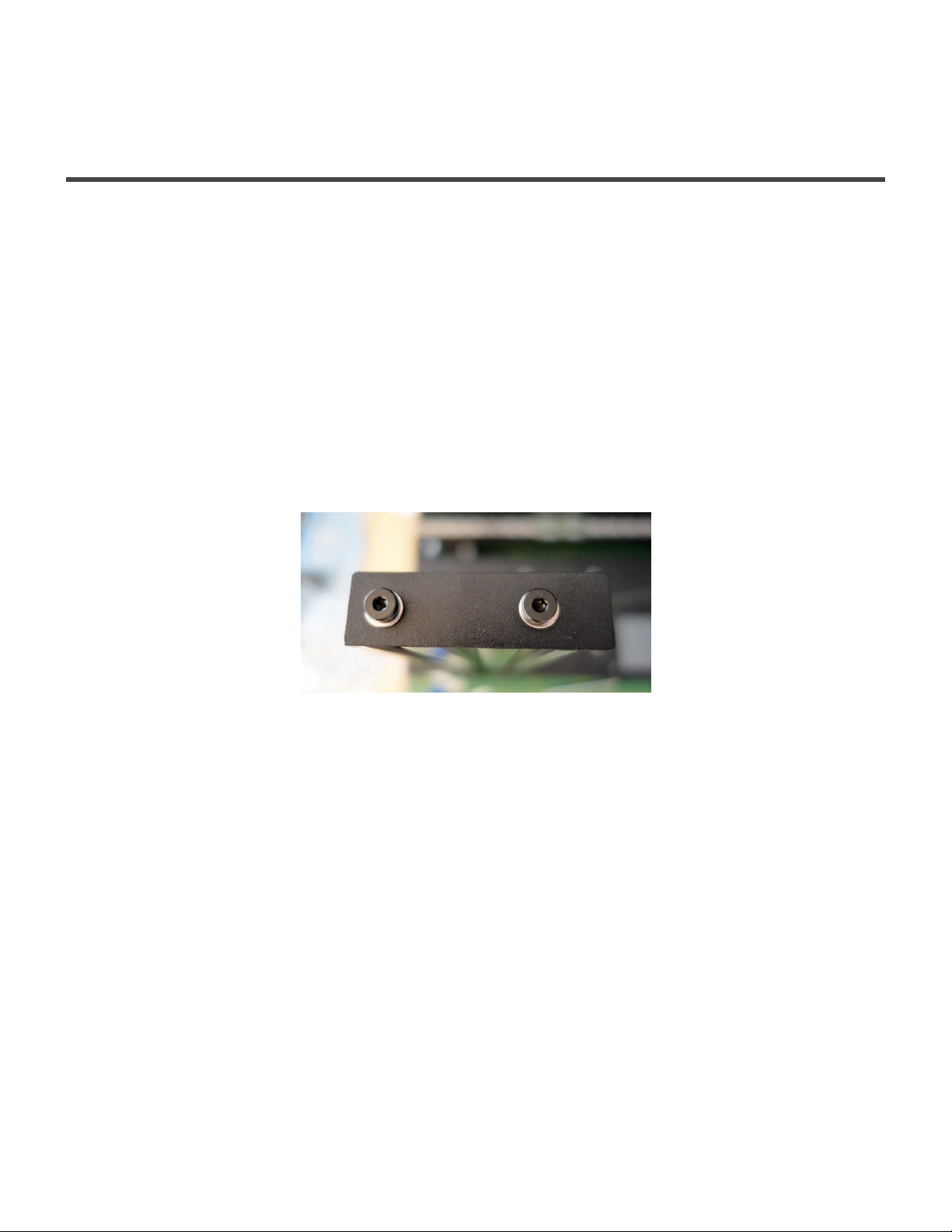
1. One end of each 450 mm extrusion is tapped. Install each Top Cap Plate using 2 each M5 × 8 SHCS
and M5 Washer onto the tapped end of the extrusion..
Installing the Z Linear Rails
Parts Required
• 2 – 380mm Linear Rails
• 2 – Rail Spacer Plates
• 30 – M3 × 10 SHCS
• 30 – M3 Post Install Nut
• 3 – Nut Alignment Jigs
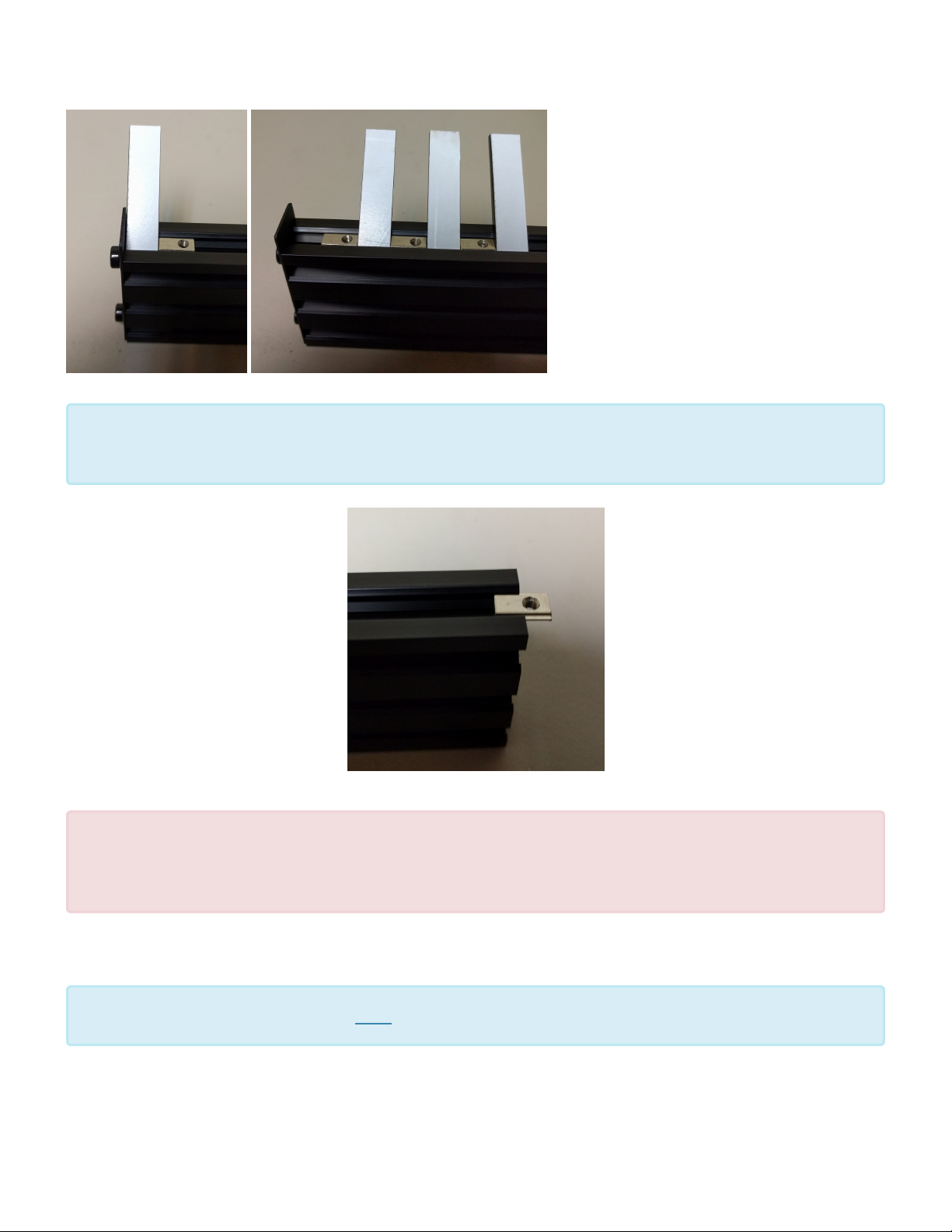
2. Install 15 M3 Post Install Nuts in each vertical extrusion and use the Nut Alignment Jig (the jigs are
12mm wide, and the color may differ from the pictured below) to properly set their spacing. As you
add additional nuts, remove the first jig and place it after the last nut until you have added 15 screws
per side. Be sure to install the nuts on the same side of the extrusion as the longer end of the
top cap.
Page 3 of 151
Page 6
Maker's Tool Works MTW Create Assembly Guide - 1
Be sure all the nuts are inserted in the same orientation or the spacing will be incorrect. For
easiest insertion, insert the end with the spring ball into the slot first as shown below
*
Use caution removing the rail from the bag. Do not allow the block to come off the rail.
!
A couple small strong magnets placed on each end of the rail can keep the blocks from
sliding off.
1. DO NOT REMOVE THE BLOCKS. They are not designed to be removed from the rail.
We highly recommend using Blue Loctite on the screws in the following steps
*
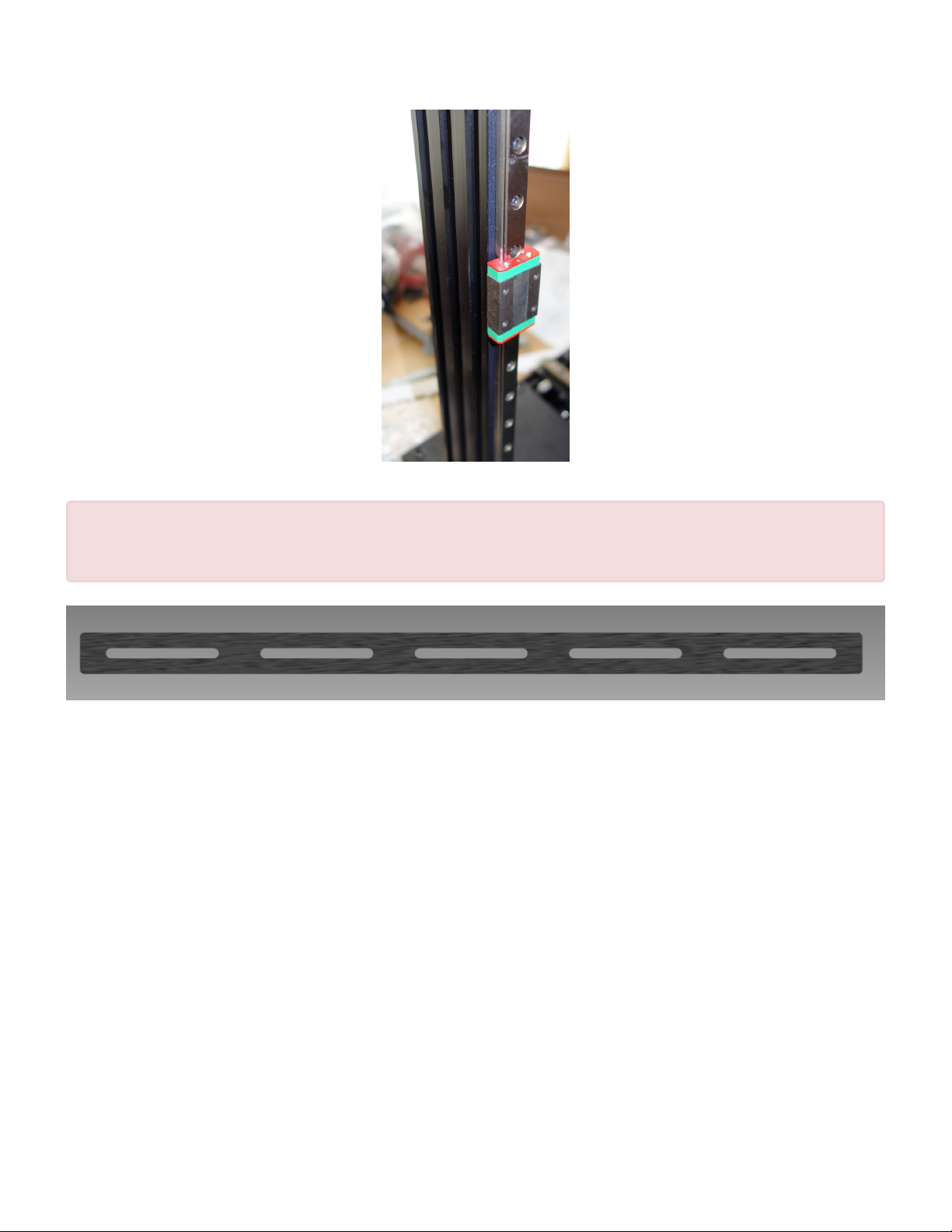
2. Install each of the 380mm Linear Rails, with the Rail Spacer Plate sandwiched between the
extrusions and the Rails. Leave the screws slightly loose.
Page 4 of 151
Page 7
Maker's Tool Works MTW Create Assembly Guide - 1
Note that the rail spacer plate (Shown below) is important. It is easy to miss in the photo
!
above. Note, the plate may have 3 slots or 5, but either function identically.
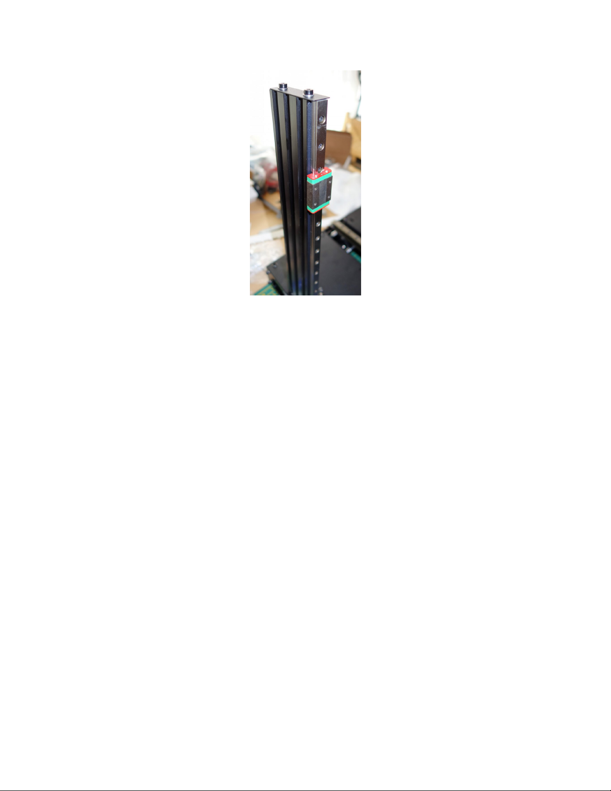
3. Slide the rails up so that the top edge of the rail is flush with the bottom of the Top Cap Plate.
Page 5 of 151
Page 8
Maker's Tool Works MTW Create Assembly Guide - 1
4. Tighten the screws holding the rails.
Page 6 of 151
Page 9

Maker's Tool Works MTW Create Assembly Guide - 1
Assembling the Base
Parts Required:
• 2 – 400mm Extrusions
• 2 – 450mm Extrusions with Z Rails pre-installed
• 2 – Machined Side Plates
• 1 – USB Adapter Plate
• 1 – IEC Adapter Plate
• 8 – M3 × 6 BHCS
• 8+ – M3 Washers
• 8 – M5 × 10 SHCS
• 8 – M5 × 16 SHCS
• 8 – M5 Washers
• 4 – M3 Post Install Nuts
• 4 – M3 × 10 SHCS
• 4 – Rubber Feet
The Machined Side Plates have a notch on one edge near the handle, that notch designates
the top of the base.
*
1. Install the USB Adapter Plate onto the Left Machined Side Plate using 4 M3 × 6 BHCS with one or
more M3 Washers as needed.
2. Repeat the last step with the IEC Adapter Plate on the Right Machined Side Plate.
Page 7 of 151
Page 10

Maker's Tool Works MTW Create Assembly Guide - 1
3. Loosely assemble the side plates to the 400mm extrusions using 8 M5 × 16 SHCSs and 8 M5
Washers. Do not tighten the screws yet.
Page 8 of 151
Page 11
Maker's Tool Works MTW Create Assembly Guide - 1
The following step needs to be completed on a known flat surface. A granite or formica
!
countertop is ideal, or flat, non-carpeted floor will work in a pinch.
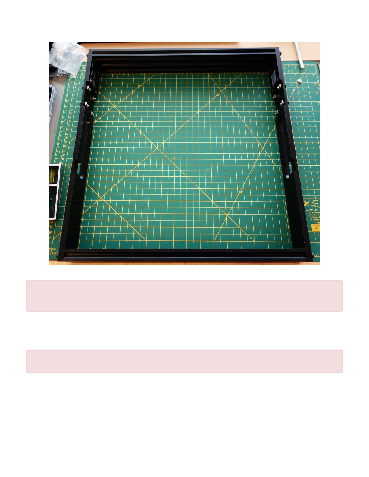
4. Sit the assembled base upside down (Machined Side Plate notch down) on a known flat surface and
tighten the screws holding the assembly, then flip the assembled base back up.
Only one end of the 450mm extrusions is tapped. Be sure to orient that end to the top.
!
5. Install the two uprights using 4 M5 × 10 SHCS, 4 M5 Washer and 4 M5 Post Install Nut each. Align
each extrusion so it is flush with the bottom of the Machined Side Plate and is pressed against the
forward edge of the cutout in the MSP to maintain proper vertical alignment.. Be sure the tapped end
of the 450mm extrusion is up!
Page 9 of 151
Page 12

Maker's Tool Works MTW Create Assembly Guide - 1
Note that the Z rails are not shown installed in the photos on this page. We revised the
assembly order to make things easier. We will update these photos soon.
*
6. On the bottom of the Machined Side Plate install one rubber foot on each end of the two extrusions
using an M3 × 10 SHCS and an M3 Post Install Nut. They should be approximately 20mm from the
end of each extrusion.
Page 10 of 151
Page 13

Maker's Tool Works MTW Create Assembly Guide - 1
7. Sit the assembled base aside for now.
Page 11 of 151
Page 14

Maker's Tool Works MTW Create Assembly Guide - 1
Assembling the Y Axis
A 3D PDF Showing just this section available to aid your assembly. For help viewing this
file, see our note here
*
Installing the Linear Rail
Parts Required
• 400mm Linear Rail
• Machined Y Plate
• 16 – M3 × 10 SHCS
• 2 – M5 × 10 SHCS
• 2 – M5 Washer
• 2 – M5 Nut
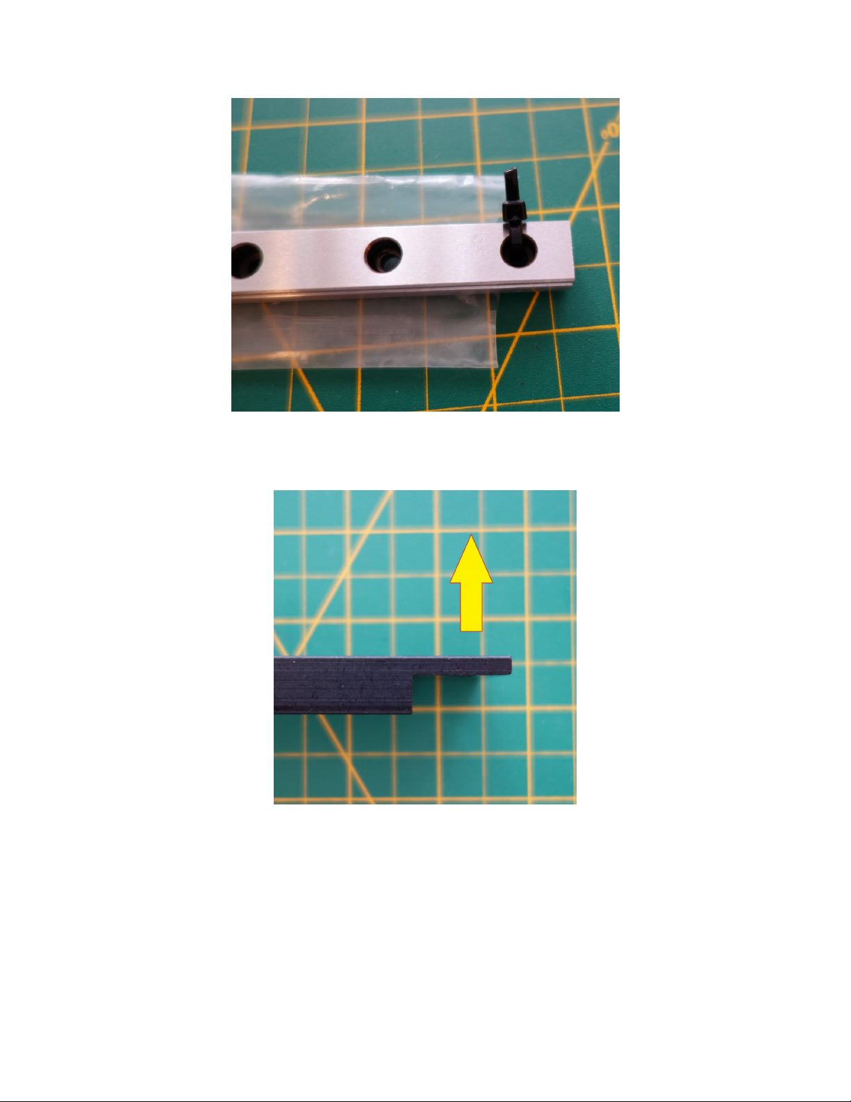
1. Carefully remove the linear rail from the bag. Remove the Zip ties on the ends.
2. DO NOT REMOVE THE BLOCKS. They are not designed to be removed from the rail. If the block
sliding feels a bit rough, it is normal, it will not affect the operation, and in time will break in.
Page 12 of 151
Page 15
Maker's Tool Works MTW Create Assembly Guide - 1
3. Be sure to orient the Machined Y Plate with the “wings” up.
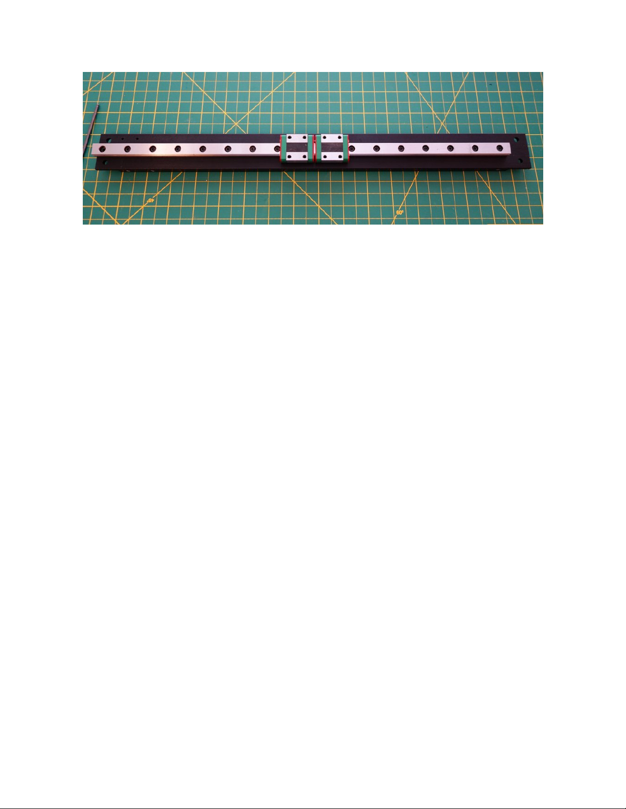
4. Install the Y axis rail using 16 M3 × 10 SHCS. The screws should be tightened until they are snug
only. Try to make sure you tighten them to a consistent level. Do not over-tighten the screws.
Page 13 of 151
Page 16
Maker's Tool Works MTW Create Assembly Guide - 1
5. We recommend adding one each M5 × 10 SHCS, M5 Washer and M5 Nut temporarily to each end to
each end of the assembly to prevent the cars from being able to come off.
Assembling the Y Motor Mount & Belt Idlers
Parts Required
• 1- Y Motor Mount
• 2 – M3 × 6 BHCS
• 2 – M3 Washer
• 1 – M5 × 8 SHCS
• 2 – M5 × 20 SHCS
• 4+ – M5 Washer
• 1 – M5 Nut
• 4 – 605zz Bearing
• 1 – Stepper Motor
• 1- Pulley
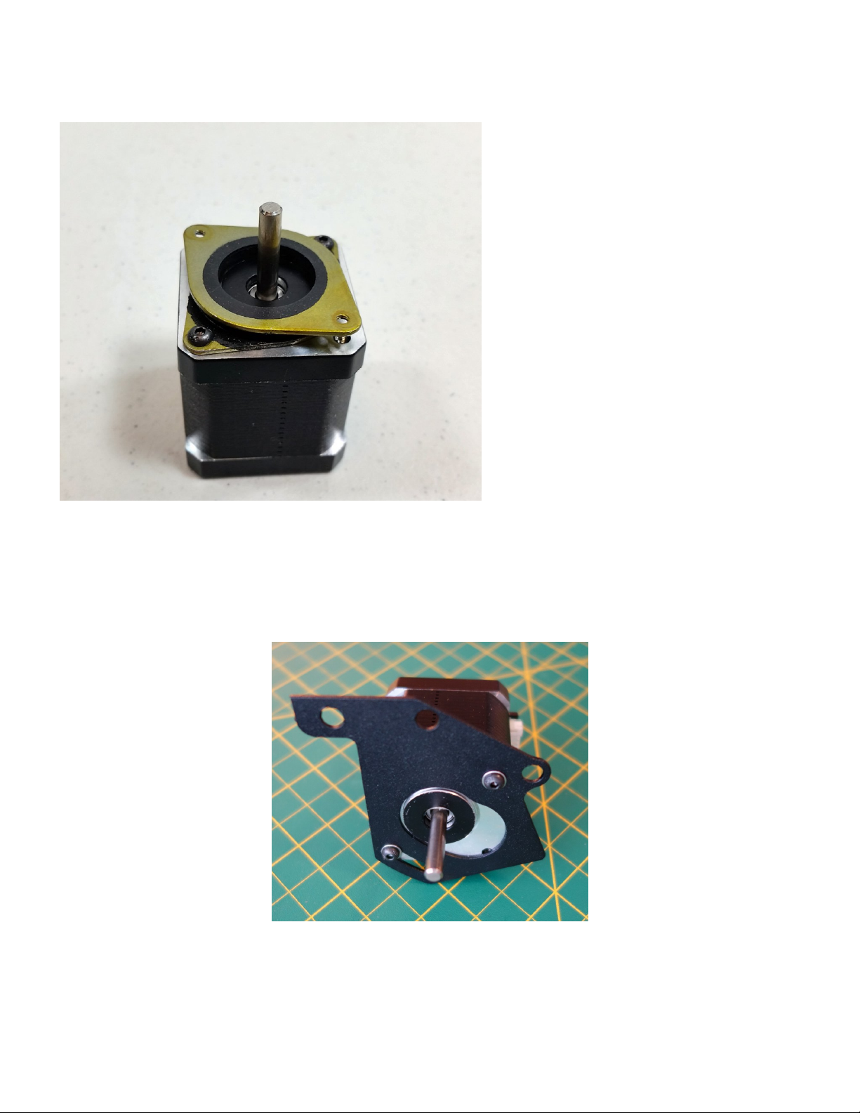
Newer Create kits are supplied with noise vibration dampening mounts. Attach the motor to the mount using
two button head M3-6 screws. two of the holes on the mount are tapped and two are not tapped. To mount
Page 14 of 151
Page 17
Maker's Tool Works MTW Create Assembly Guide - 1
the motor to the mount use the two holes that are not tapped.
1. Install the Y Motor assembly with 2 M3 × 6 BHCS and 2 M3 Washer. These screws will insert into the
tapped holes of the vibration dampening mount. See the pictures below for the proper orientation
relative to the rest of the assembly. Be sure that the motor is in the uppermost position so when we
later install the belt you have plenty of room to adjust it.
Page 15 of 151
Page 18
Maker's Tool Works MTW Create Assembly Guide - 1
2. Install the pulley, leaving about 1-2mm between the bottom of the pulley and the top of the motor.
Install it with the set screw end of the pulley away from the motor. Be sure one of the pulley set
screws is aligned with the flat of the motor shaft.
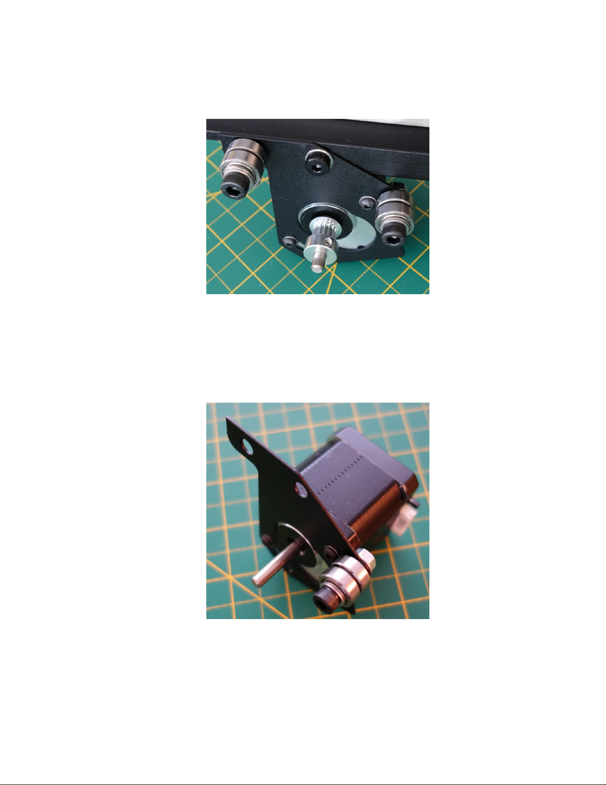
3. All three Idlers will Install in the following order: M5 × 20 SHCS > Zero or more M5 Washer as needed
> 605zz Bearing > M5 Washer > 605zz Bearing > M5 Washer > Y Motor Mount or Machined Y
Plate. The two upper idlers will screw directly into the tapped holes on the Machined Y Plate. The
lower idle will screw into an M5 Nut Use as many washers below the screw head as needed to keep
the bearings snugly in place (probably 2-3).
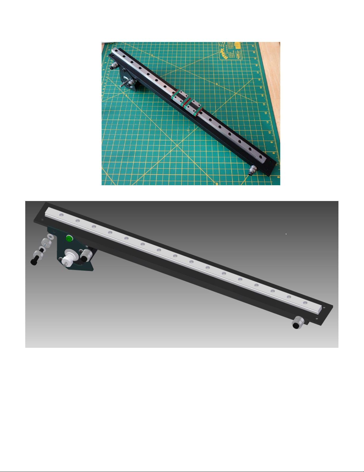
4. Locate the two 5mm tapped holes on the side of the Machined Y Plate and attach the Y motor plate
using an Idler Bearing assembly and an M5 × 10 SHCS with a M5 Washer. See the images below for
clarification.
Page 16 of 151
Page 19
Maker's Tool Works MTW Create Assembly Guide - 1
Sit the assembled Y Axis aside for the time being.
Page 17 of 151
Page 20

Maker's Tool Works MTW Create Assembly Guide - 1
Assembling the X Axis
Assembling the X Motor Mount
Parts Required
• 1 – X Motor Mount
• 1 – Stepper Motor
• 1 – Pulley
• 4 – M3 × 6 BHCS
• 4 – M3 Washer
• 2 – M5 × 20 SHCS
• 8+ – M5 Washer
• 2 – M5 Nut
• 4 – 605zz Bearing
1. Install the idlers in two 5mm holes, using the following order: M5 × 20 SHCS > 605zz Bearing > M5
Washer > 605zz Bearing > M5 Washer > X Motor Mount > M5 Nut.
Page 18 of 151
Page 21
Maker's Tool Works MTW Create Assembly Guide - 1
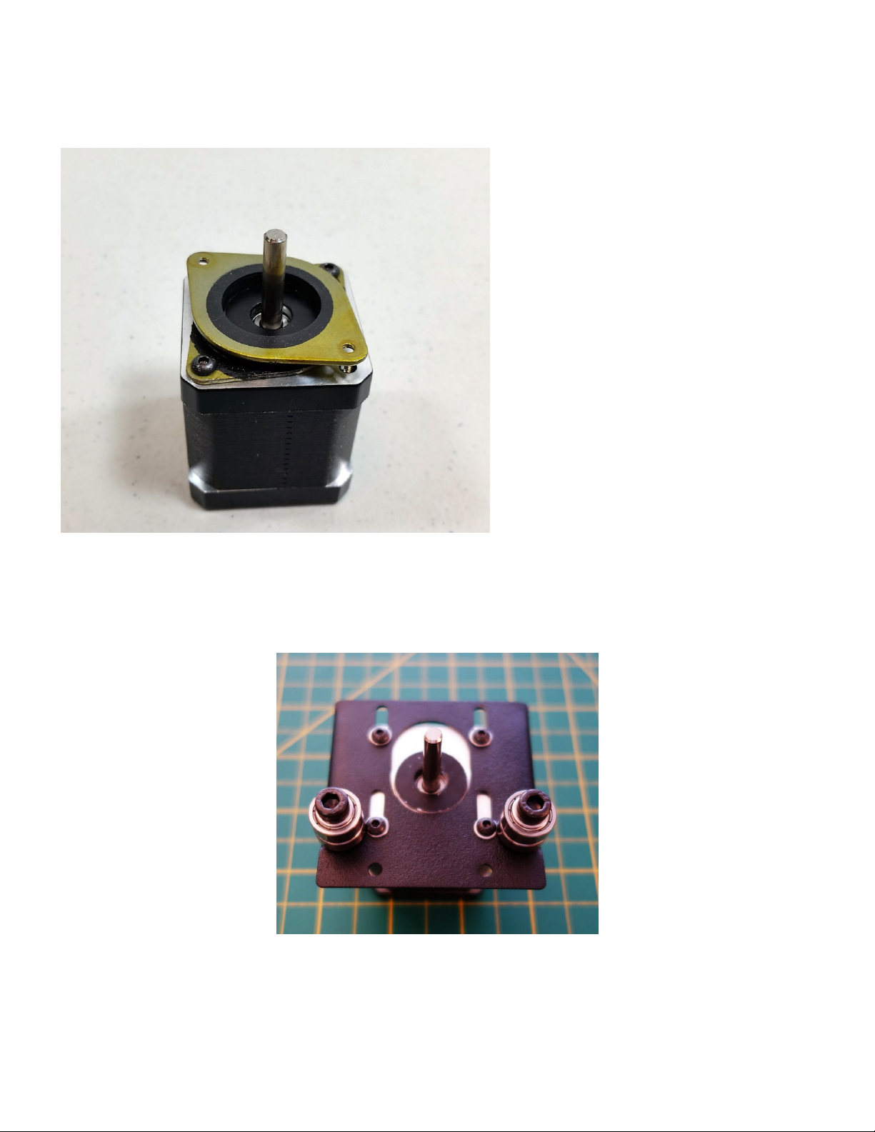
New Create kits are provided with a vibration dampening mount for this axis. Two of the holes on the mount
are not tapped. Use these holes and two m3-6 button head screws to attach the mount to the stepper motor.
2. Install the Stepper Motor Assembly using 2 M3 × 6 BHCS and 2 M3 Washer. Two of the slots of the
motor mount plate will not be used. Mount it in the position closest to the idlers. Make sure the port on
the motor where the cable connects faces the rear of the printer.
Page 19 of 151
Page 22
Maker's Tool Works MTW Create Assembly Guide - 1
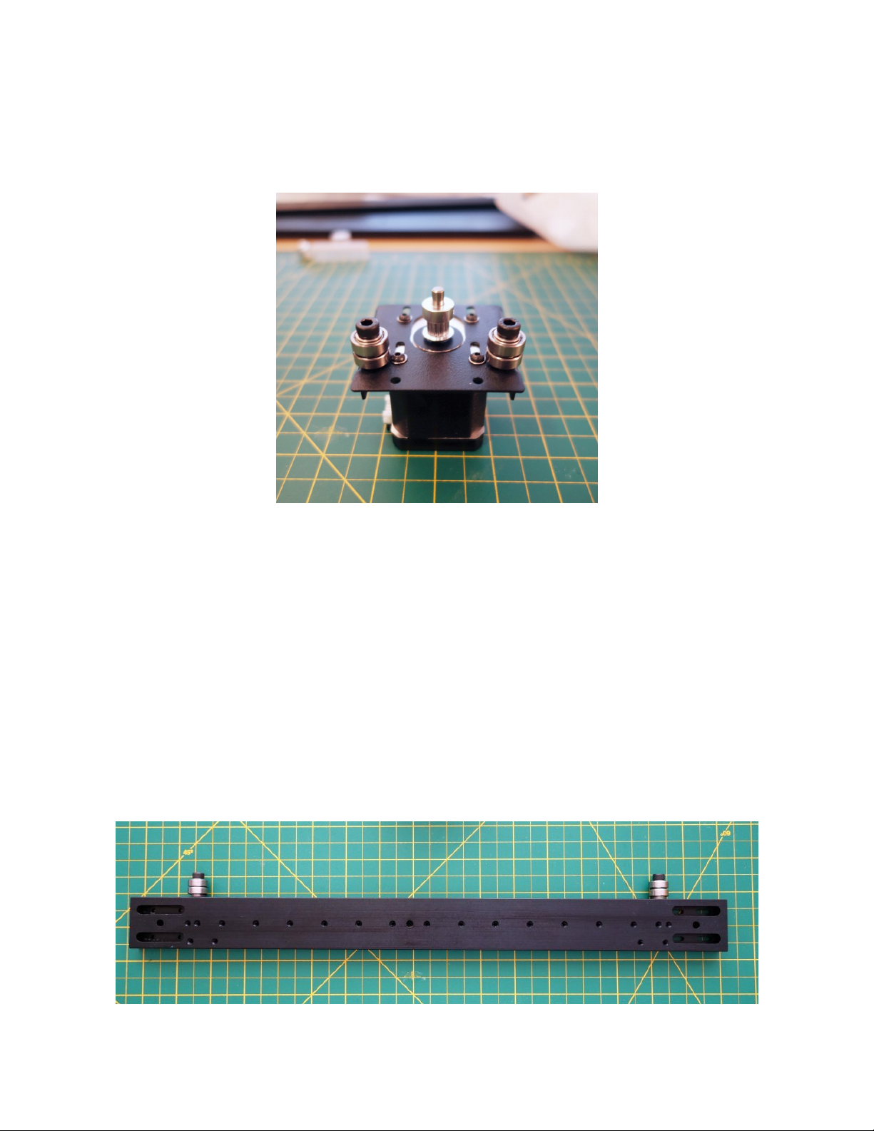
3. Install the pulley, leaving about 1-2mm between the bottom of the pulley and the top of the motor
mount plaTE. Install it with the set screw end of the pulley toward the motor (The opposite of how it
pictured). Be sure one of the pulley set screws is aligned with the flat of the motor shaft.
Installing the Idlers
Parts Required
• 2 – M5 × 20 SHCS
• 8+ – M5 Washer
• 4 – 605zz Bearing
1. Install the idlers in two 5mm tapped holes, using the following order: M5 × 20 SHCS > zero or more
M5 Washer as needed > 605zz Bearing > M5 Washer > 605zz Bearing > M5 Washer > Machined X
Plate. Use 2-3 washers below the bearings as pictured.
Page 20 of 151
Page 23
Maker's Tool Works MTW Create Assembly Guide - 1
Mounting the Linear Rail
Parts Required
• 1 – Machined X Plate Assembly
• 1 – 380mm Rail Assembly
• 15 – M3 × 10 SHCS
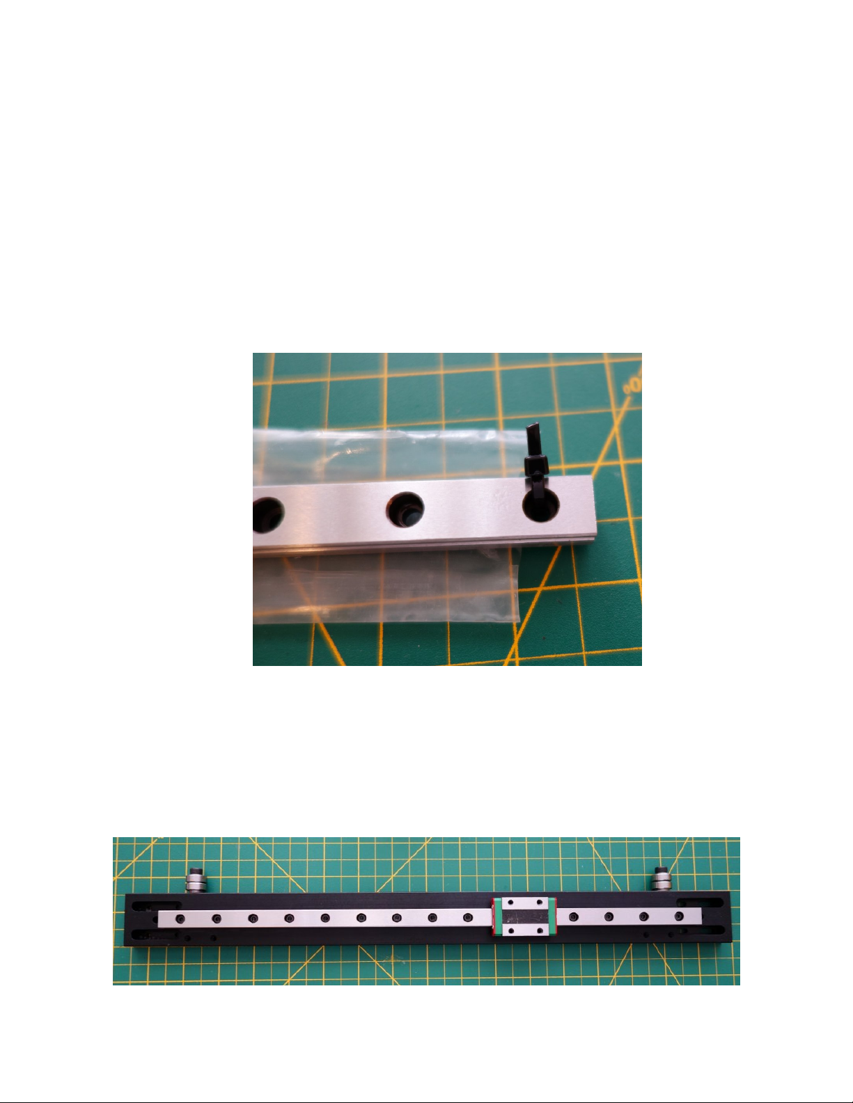
1. Carefully remove the 380mm Rail Assembly from the bag. Watch closely for any loose balls in the
bag. If you find any contact our support for instructions on how to re-insert them. Cut off the zip ties
on the ends.
2. DO NOT REMOVE THE BLOCK. They are not designed to be removed from the rail.
3. Install the 380mm Rail Assembly on the side of the Machined X Plate with the machined slots using
15 M3 × 10 SHCS. The screws should be tightened until they are snug only. Try to make sure you
tighten them to a consistent level. Do not over-tighten the screws.
Page 21 of 151
Page 24
Maker's Tool Works MTW Create Assembly Guide - 1
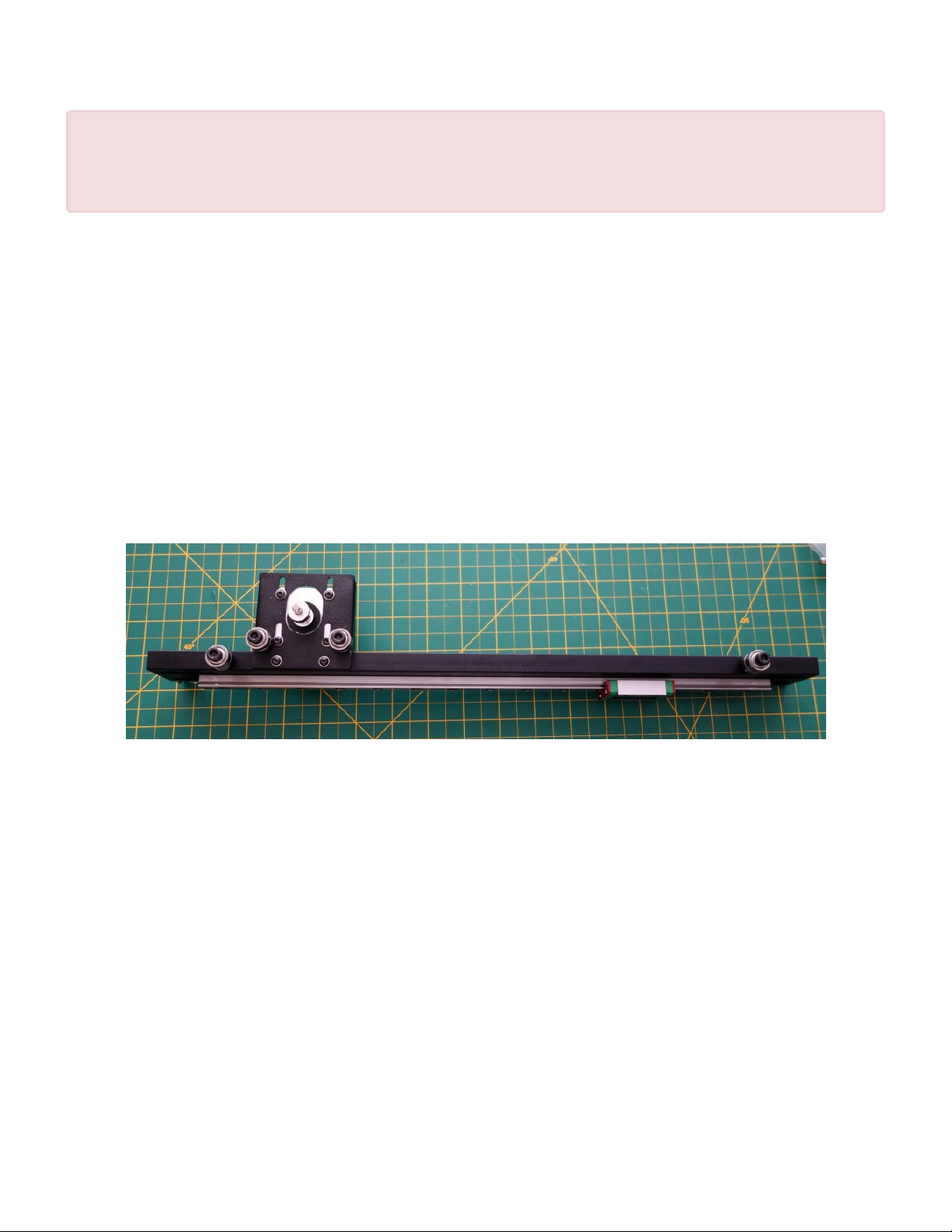
Handle the assembly carefully after this point. Until it is fully installed, the cars can come off
!
the end of the rail. A couple small strong magnets placed on each end of the rail can keep
the blocks from sliding off.
Installing the X Motor Mount
Parts Required
• Machined X Plate Assembly
• X Motor Mount assembly
• 2 – M3 × 6 BHCS
• 2 – M3 Washer
1. Mount the X Motor Mount Assembly to the X Axis Assembly using 2 M3 × 6 BHCS and 2 M3
Washer.
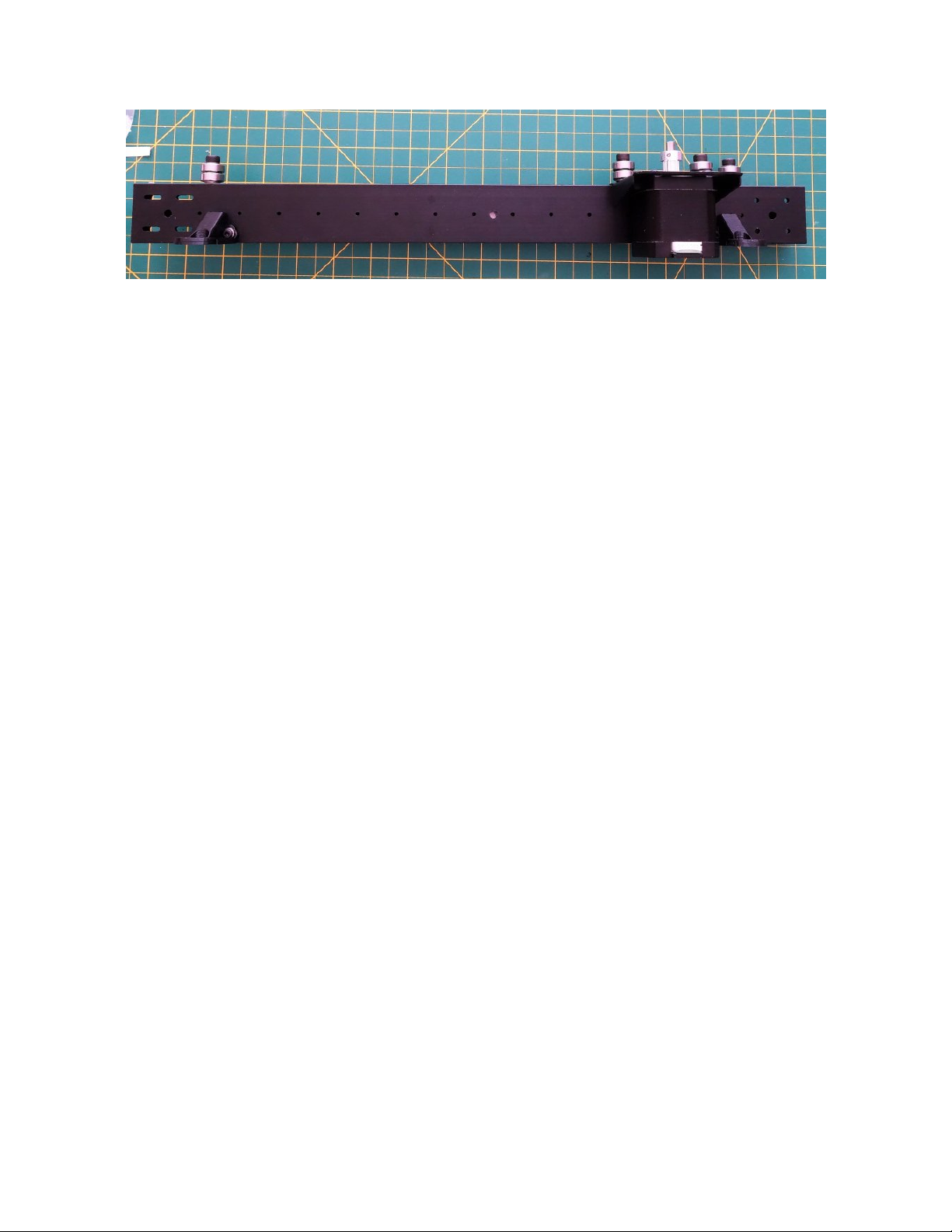
Installing the Lead Nut Adapters
Parts Required
• 2 – Printed Lead Nut Adapters
• 4 – M3 × 10 SHCS
• 4 – M3 Washer
• Install the two Lead Nut Adapters using two M3 × 10 SHCS with M3 Washers
Page 22 of 151
Page 25
Maker's Tool Works MTW Create Assembly Guide - 1
Page 23 of 151
Page 26

Maker's Tool Works MTW Create Assembly Guide - 1
Assembling the OctoPi LCD
Assembling the X Motor Mount
Parts Required
- RPi3
- LCD
- HDMI coupler
- LCD hardware
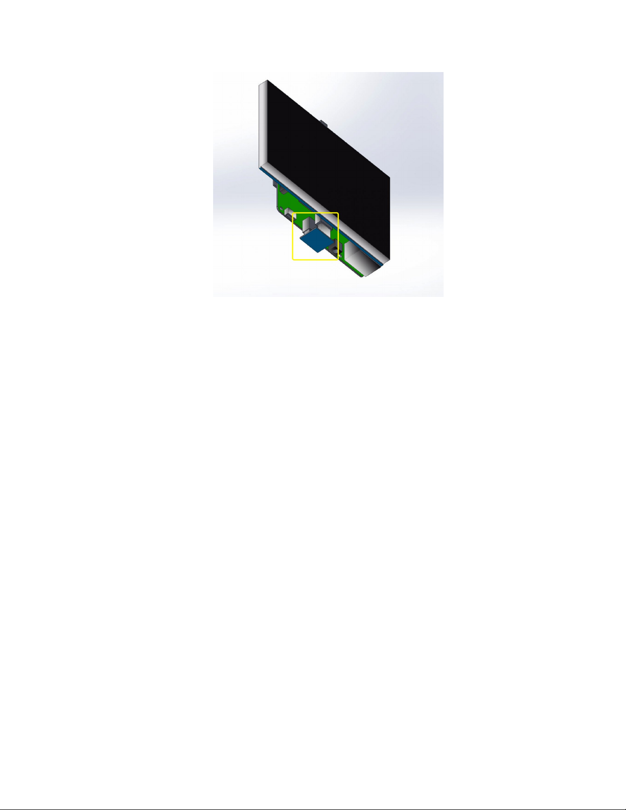
1. Attach the LCD to the Pi. Line up the pins on the PI with the sockets in the back of the LCD.
Use the hardware supplied with the LCD to ensure solid connection.
Make sure the hdmi ports on the LCD and the Pi line up
2. Connect the LCD hdmi to the Pi hdmi using the supplied HDMI coupler
Page 24 of 151
Page 27
Maker's Tool Works MTW Create Assembly Guide - 1
Page 25 of 151
Page 28
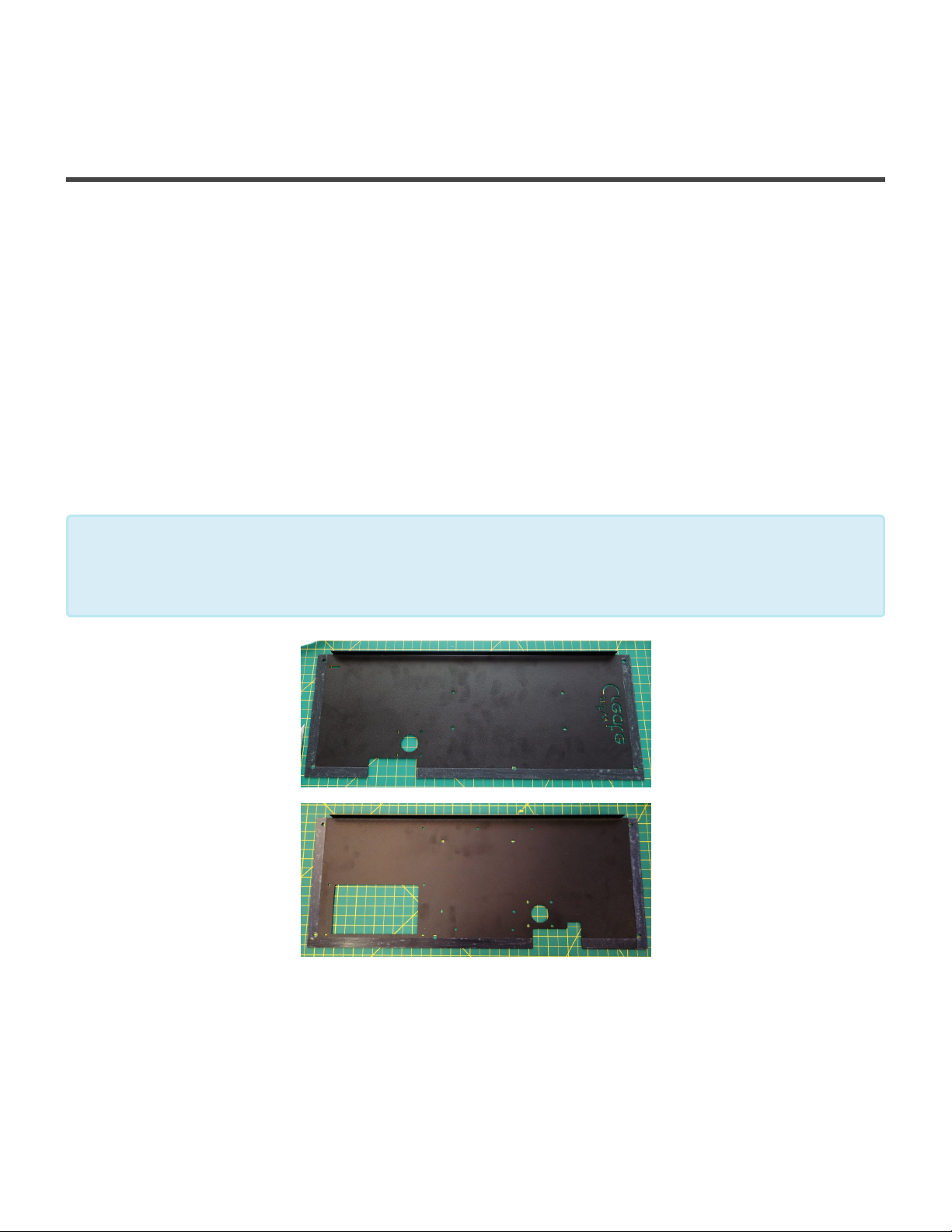
Maker's Tool Works MTW Create Assembly Guide - 1
Assemble the Top Deck plates
Assemble the Top Deck – Right Side
Parts Required
• Top Deck Right (includes the MTW Create Logo)
• Power Supply
• 1 – Stepper Motor
• 4 – M3 × 6 BHCS
• 4 – M3 Washers
• 4 – M4 × 5 SHCS
• 4 – M5 Washers
You may optionally apply a couple layers of rubber cement to the outside edges of the top
deck plates, to assist with noise reduction. Place the the cement where the tape is on the
*
picture below.
1. Mount the Stepper Motor using 4 M3 × 6 BHCS and 4 M3 Washers, leave the motor slightly loose
until the deck plate is installed.
2. Mount the Power Supply using 4 M4 × 5 SHCS and 4 M5 Washers.
Page 26 of 151
Page 29

Maker's Tool Works MTW Create Assembly Guide - 1
!
Make sure to set the PSU to the appropriate voltage!
3. Set the assembly aside.
Assemble the Top Deck – Left Side
Parts Required
• Top Deck Left (includes the cutout for the LCD)
• RAMBo Controller
• 1 – Stepper Motor
• 4 – M3 × 6 BHCS
• 17 – M3 Washers
• 9 – M3 × 10 SHCS
• 4 – M3 × 16 SHCS
• 17 – M3 Nuts
• 4 – Nylon Spacers
• 2 – Printed LCD Mounts
• LCD
Page 27 of 151
Page 30
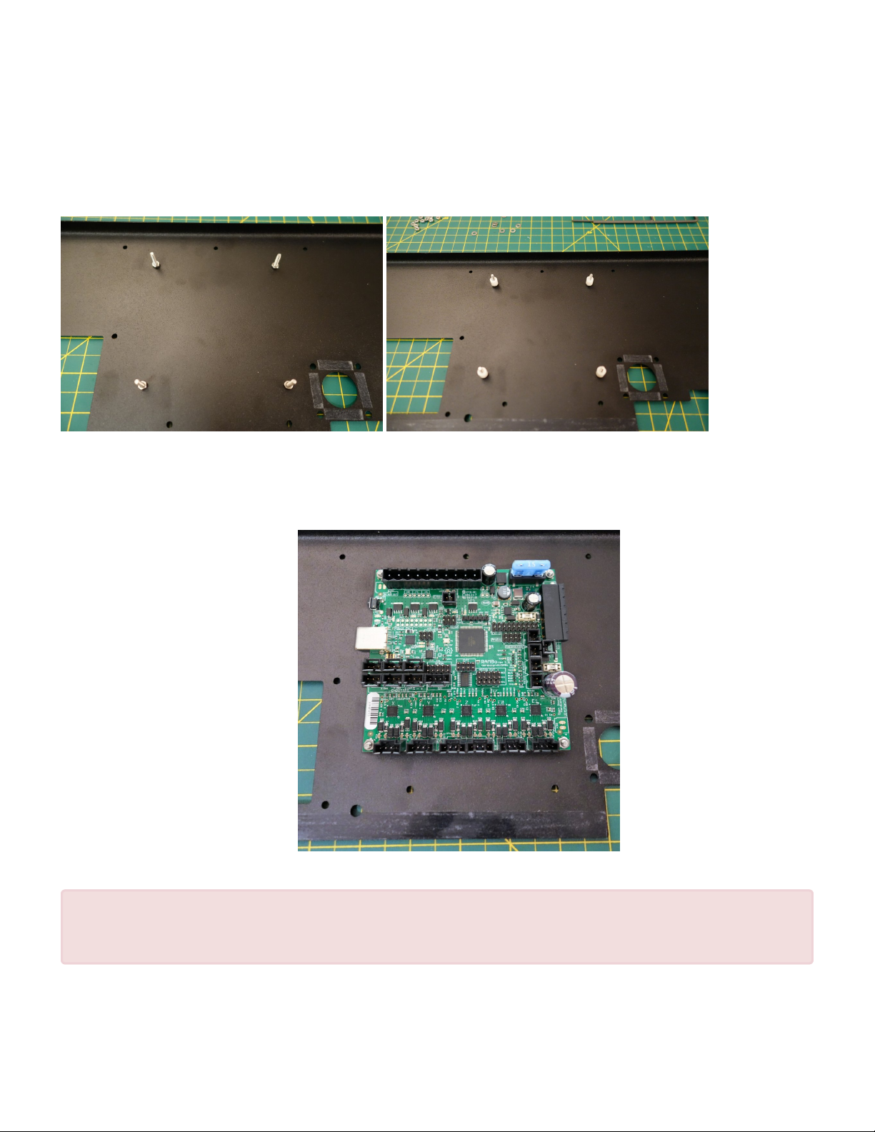
Maker's Tool Works MTW Create Assembly Guide - 1
1. Install the screws to mount the RAMBo Controller using 4 M3 × 16 SHCS and 4 M3 Nuts. Installing
the screws like this makes the following steps much easier and simplifies any future maintenance.
Leave these nust just slightly loose to allow you to reposition the screws if needed when installing the
RAMBo Controller, and put the 4 Nylon Spacers on the screws.
2. Install the RAMBo Controller onto the pre-installed studs using 4 Nylon Spacers to offset it from the
metal. Use 4 M3 Nuts to hold it in place. Orient it with the USB toward toward the front of the printer
for easier connection to the RPi.
Tighten the nuts holding the RAMBo Controller, carefully so not to damage any of the board
!
components.
Page 28 of 151
Page 31
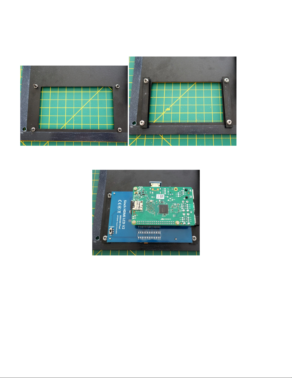
Maker's Tool Works MTW Create Assembly Guide - 1
3. Install the two Printed LCD Mounts using 2 M3 × 10 SHCS, 2 M3 Washers, and 2 M3 Nuts followed
by 2 M3 Nuts on each piece. Leave the screws loose.
4. Install the LCD by carefully sliding it into place between the Printed LCD Mounts.
5. Tighten the screws.
6. Mount the Stepper Motor using 4 M3 × 6 BHCS and 4 M3 Washer, leave the motor slightly loose
until the deck plate is installed.
Page 29 of 151
Page 32
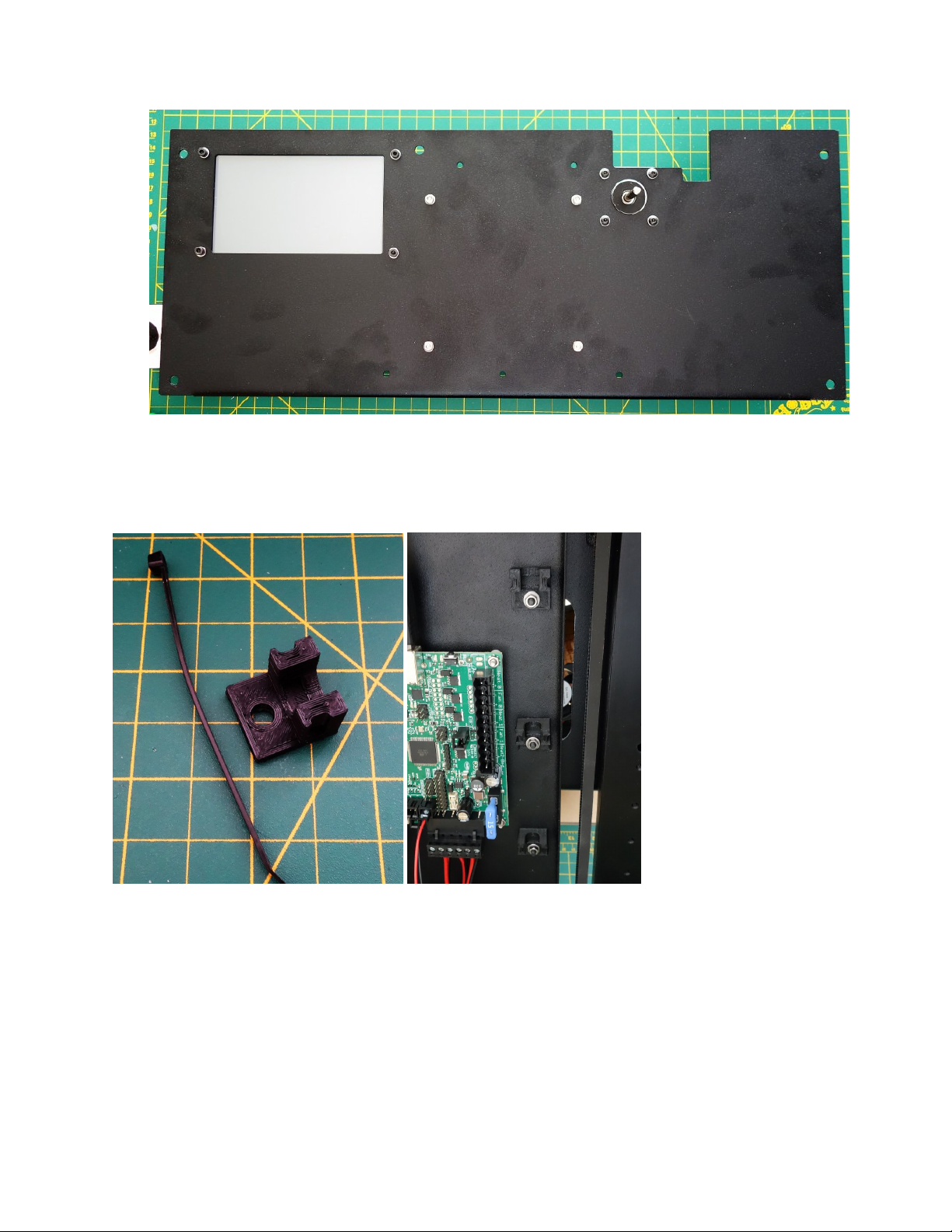
Maker's Tool Works MTW Create Assembly Guide - 1
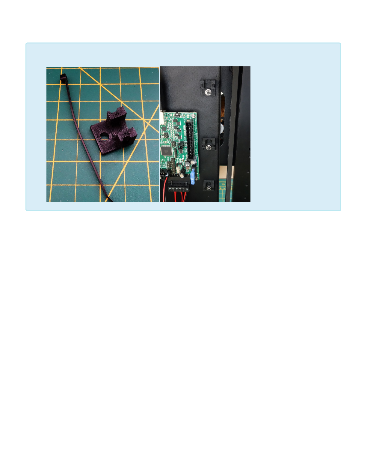
7. The kit comes with a number of printed clips for easier wire management. Those attach to the deck
plate with one M3 × 10 SHCS, one M3 Washer and one M3 Nut each. You sill install 3 along the
“inside” and two along the “outside” edge of the RAMBo.
Page 30 of 151
Page 33
Maker's Tool Works MTW Create Assembly Guide - 1
Install the Y Axis & Top Deck Plates
Install the Top Deck Left
Parts Required
• Base Assembly
• Top Deck Left assembly
• 4 – M5 × 8 SHCS
• 4 – M5 Washer
• 4 – M5 Post Install Nut
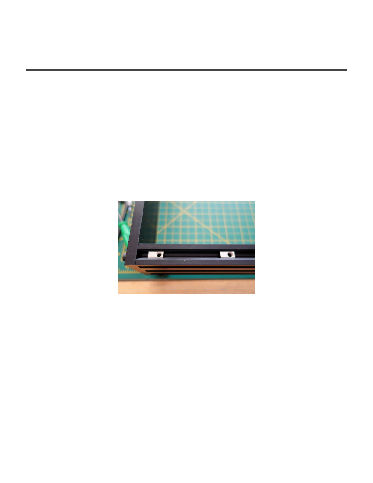
1. Insert 4 M5 Post Install Nut into the top of the extrusions, two on the front and two in the back.
2. Align the M5 Post Install Nut with the holes in the Top Deck Left Assembly and mount with 4 M5 × 8
SHCS and 4 M5 Washer. Leave slightly loose.
Page 31 of 151
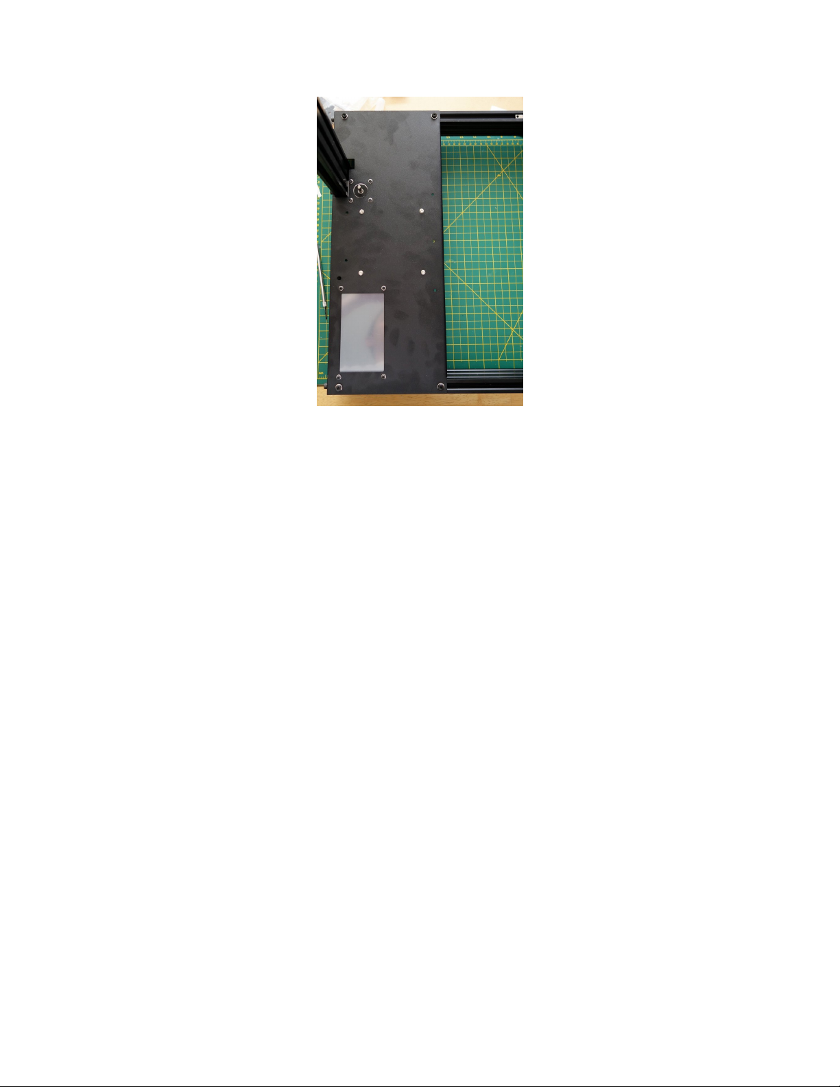
Page 34
Maker's Tool Works MTW Create Assembly Guide - 1
3. Align the assembly with the left edge of the base, so the motor is touching the vertical upright and
tighten the plate, then the motor.
Install the Y Axis Assembly
Parts Required
• Base Assembly
• Y Axis Assembly
• 4 – M5 × 10 SHCS
• 4 – M5 Washer
• 4 – M5 Post Install Nut
1. Insert 4 M5 Post Install Nut into the top of the extrusions, two on the front and two in the back.
Page 32 of 151
Page 35
Maker's Tool Works MTW Create Assembly Guide - 1
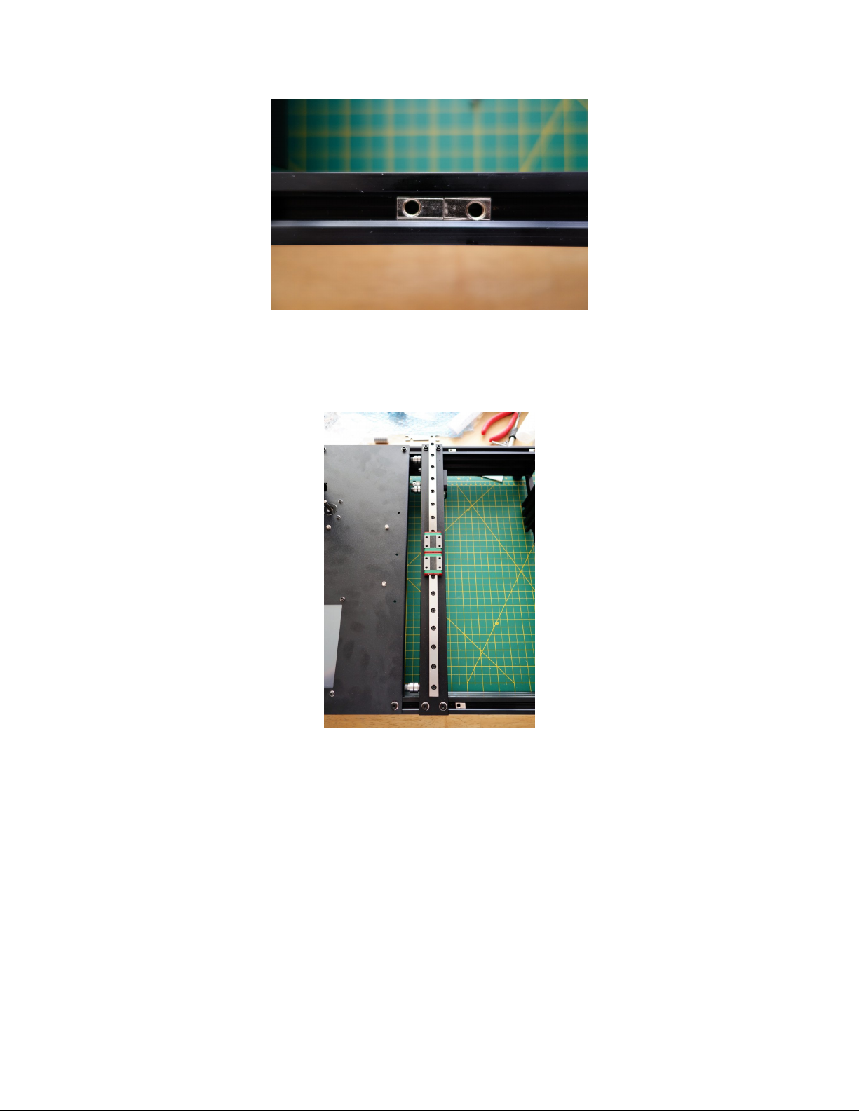
2. Align the M5 Post Install Nut with the holes in the Y Axis Assembly and mount with 4 M5 × 10 SHCS
and 4 M5 Washer. Leave slightly loose.
3. Align the assembly so there is about a 1mm gap between the idler screw head and the bend on the
Top Deck Left Assembly and tighten.
Install the Top Deck Right
Parts Required
• Base Assembly
• Top Deck Rightt Assembly
• 4 – M5 × 8 SHCS
Page 33 of 151
Page 36
Maker's Tool Works MTW Create Assembly Guide - 1
• 4 – M5 Washer
• 4 – M5 Post Install Nut
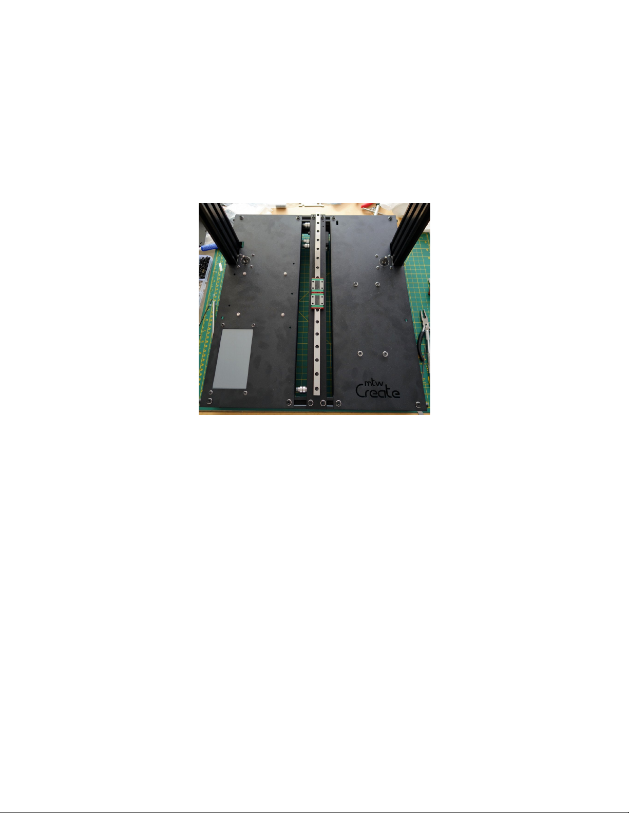
1. Insert 4 M5 Post Install Nut into the top of the extrusions, two on the front and two in the back.
2. Align the M5 Post Install Nut with the holes in the Top Deck Right Assembly and mount with 4 M5 × 8
SHCS and 4 M5 Washer. Leave slightly loose.
3. Align the assembly with the right edge of the base, so the motor is touching the vertical upright and
tighten the plate, then the motor.
Install the Z Motor Supports
Parts Required
• Base Assembly
• 2 – Z Motor Support
• 4 – M5 × 10 SHCS
• 4 – M5 Washer
• 4 – M5 Post Install Nut
1. Flip the base over so it is lying on it’s back.
Page 34 of 151
Page 37
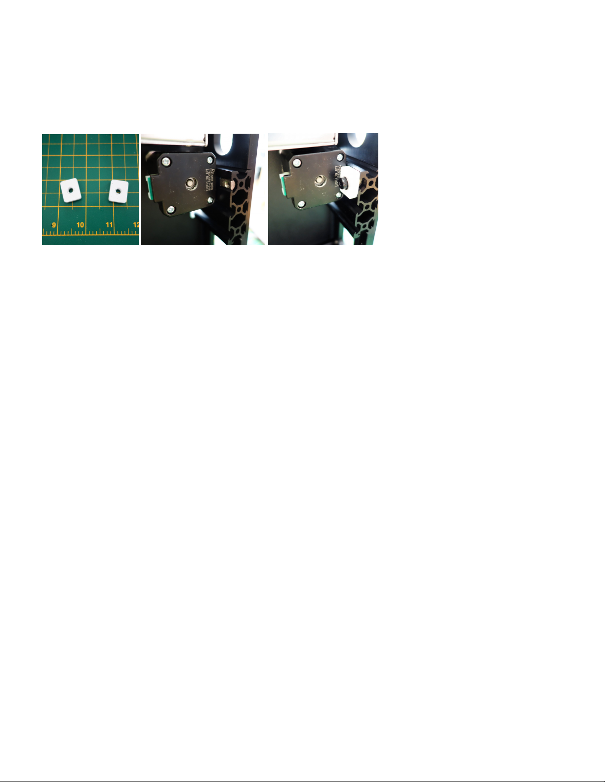
Maker's Tool Works MTW Create Assembly Guide - 1
2. Install the Z Motor Support to the inside of the vertical extrusions so they are pushed firmly against
the bottom of the Z motors. You will install one per side using one each M5 Post Install Nut, M5 × 10
SHCS, and M5 Washer.
Page 35 of 151
Page 38
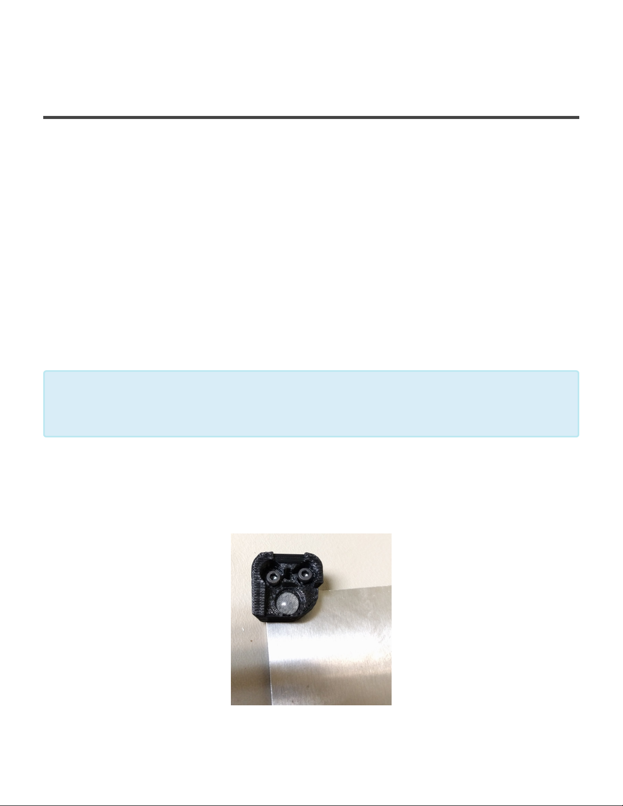
Maker's Tool Works MTW Create Assembly Guide - 1
Assembling the Y Carriage
Assembling the Y Carriage Plate
Parts Required
• 1 – Y Carriage Plate
• 4 – Printed Glass Mount
• 1 – Y Belt Offset
• 4 – M3 × 6 BHCS
• 10 – M3 × 10 SHCS
• 4 – M3 × 16 SHCS
• 4 – M3 Washer
• 14 – M3 Nut
• 4 – Silicone dots
Note: The Y Carriage Plate was redesigned shortly before the MTW Create Kits shipped,
and some of the photos shown here still reflect the older version. The basic assembly
*
remains the same in spite of the minor changes.
1. Install the 4 Silicone Dots into the Printed Glass Mounts.
2. Install the Printed Glass Mounts onto the Y Carriage Plate using 2 M3 × 10 SHCS for each mount.
Leave the mounts loose for now.
Page 36 of 151
Page 39
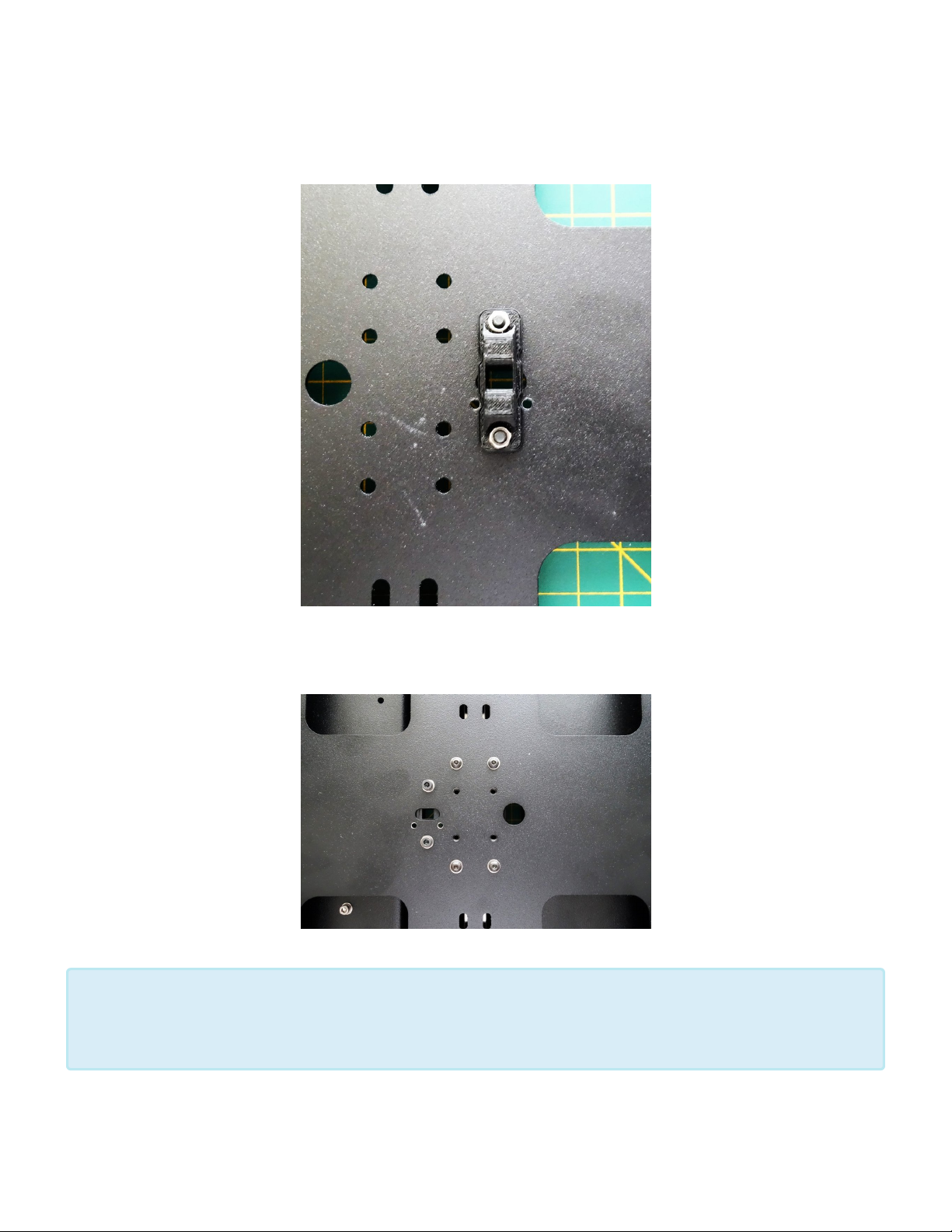
Maker's Tool Works MTW Create Assembly Guide - 1
3. Install the Y Belt Offset using two M3 × 10 SHCS with M3 Washers. Note the screws now go up from
the bottom into the tapped holes on the Y Carriage Plate.
4. Mount the Y Carriage Plate onto the Y Axis Assembly, using 4 M3 × 6 BHCS and four M3 Washer.
Some early kits have 8 mounting holes on the Y carriage. You will only use the four
outermost holes, with two screws into each of the two blocks. Using all 8 mounting holes
*
can lead to binding.
Page 37 of 151
Page 40
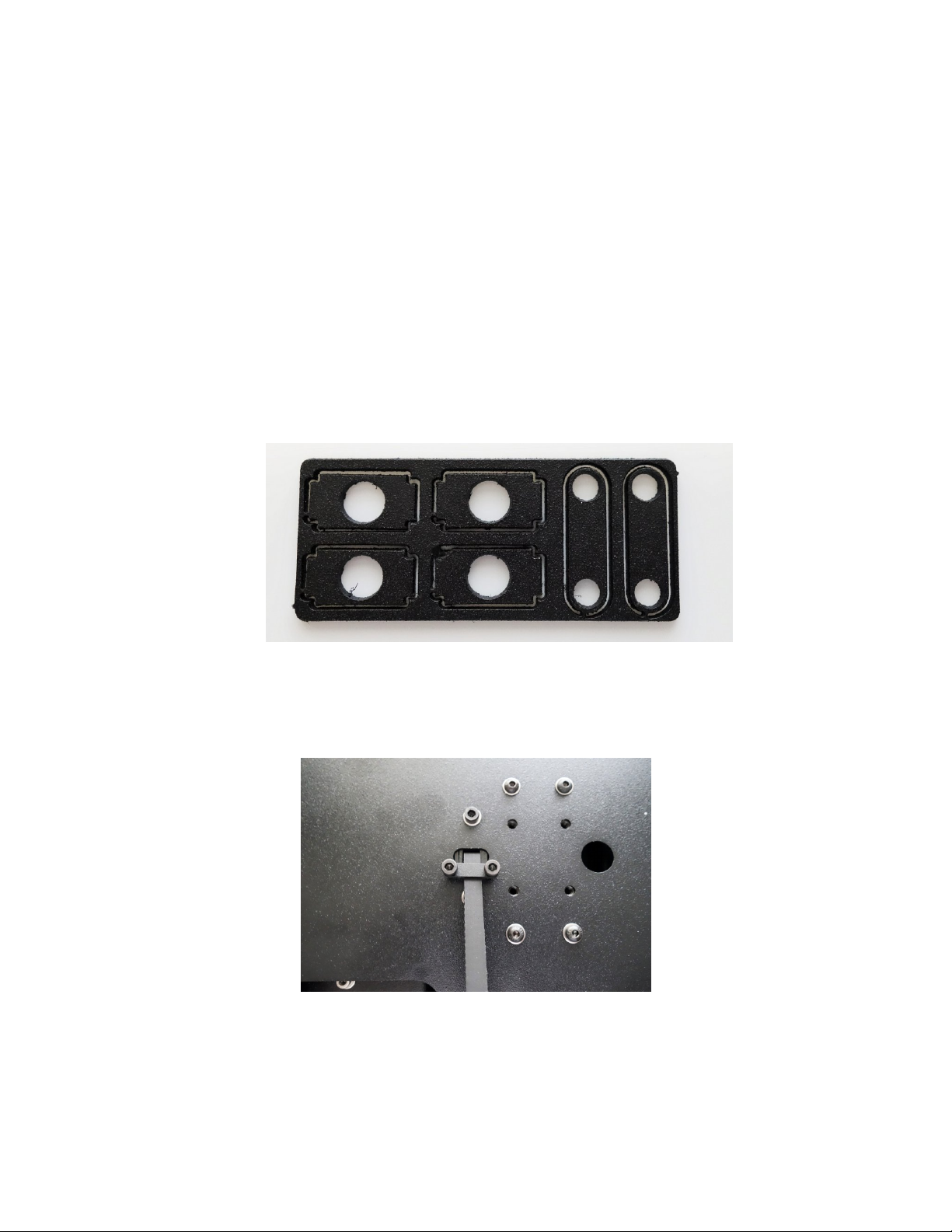
Maker's Tool Works MTW Create Assembly Guide - 1
Installing the Y Belt
Parts Required
• 1 – Timing Belt
• Y Belt Clip
• 2 – M3 × 10 SHCS
• 2 – M3 Washer
• 2 – M3 Nut
1. Sit the printer on it’s side with the Y Belt path facing up.
2. Find the plate shown below, and break out the Y Belt Clip – the piece with two holes.
3. Insert the Belt ends through the slot in the Y Belt Offset and loosely hold in place with the Y Belt Clip
using 2 M3 × 10 SHCS.
4. Wrap the belt around the pulley and idles as shown below.
Page 38 of 151
Page 41
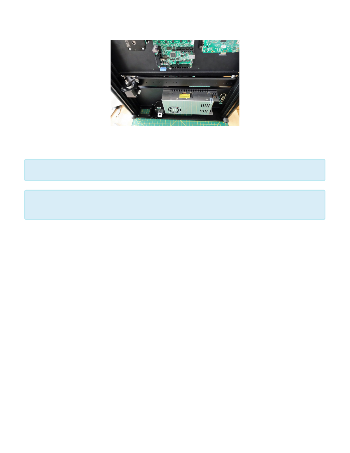
Maker's Tool Works MTW Create Assembly Guide - 1
5. Pull the ends of the belt until it is just barely tight.and tighten the the belt clip screws.
Do not overtighten the belt, you will properly tension the belt in a later step.
*
Do not clip the belt ends yet. Wait to clip them until the assembly is complete and you are
absolutely certain that no changes need to be made.
*
6. Move the Y carriage back and forth several times to check the belt alignment and tracking, and adjust
the pulley position and the position of the belt ends as needed to make it track correctly.
Page 39 of 151
Page 42
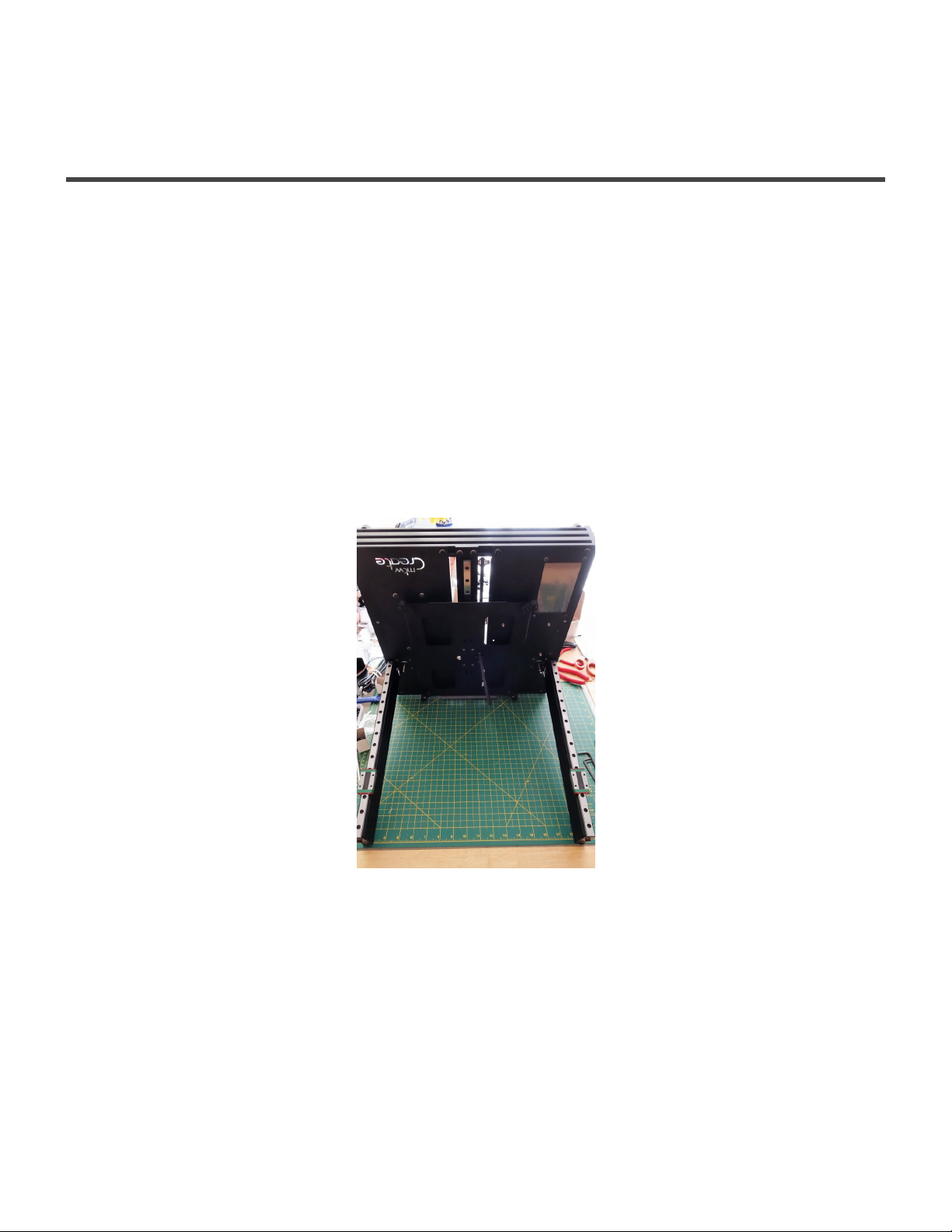
Maker's Tool Works MTW Create Assembly Guide - 1
Installing the X Axis
Install the X axis
Parts Required
X Axis Assembly
4 – M3 × 6 BHCS
4 – M3 × 10 SHCS
8 – M3 Washer
4 – O-Ring
1. Turn the printer on it’s back with the vertical extrusions pointing towards you.
2. Mount the right end (when the printer is upright that will be the left end) of the X axis to the Z rails
using four M3 × 6 BHCS without washers.. Leave the screws just slightly loose.
Page 40 of 151
Page 43
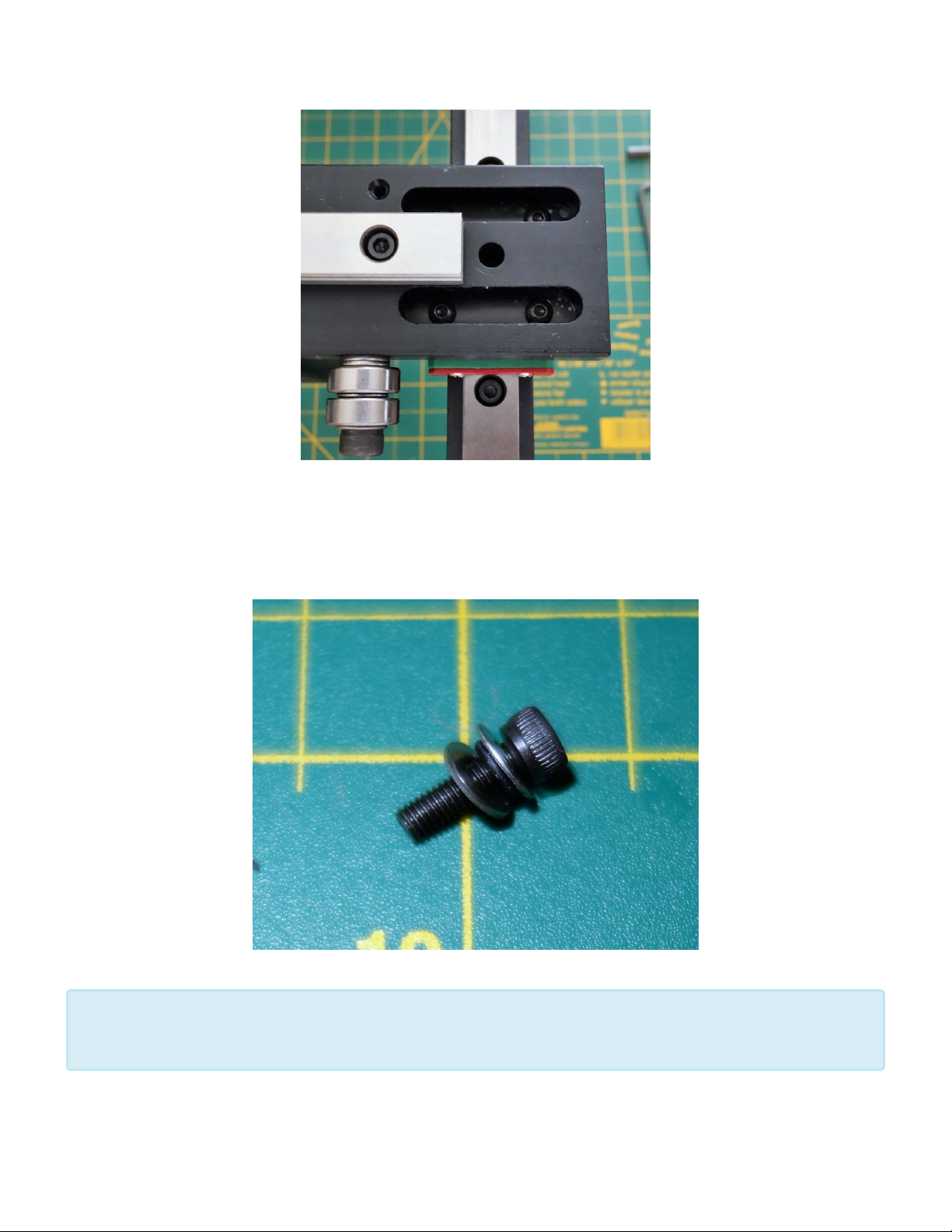
Maker's Tool Works MTW Create Assembly Guide - 1
3. Mount the left side (when the printer is upright that will be the right side) using four M3 × 10 SHCS, 8
M3 Washer, and four O-RIngs. Assemble in the following order: M3 × 10 SHCS > M3 Washer > O-
Ring > M3 Washer > X Axis plate. Leave the screws slightly loose.
The O-Rings here help allow for any slight misalignment, guaranteeing smooth, bind-free
movement.
*
Page 41 of 151
Page 44
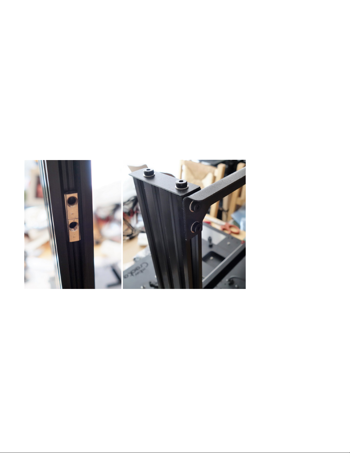
Maker's Tool Works MTW Create Assembly Guide - 1
Installing the Top Crossbar
Parts Required
Top Crossbar
4 – M5 × 8 SHCS
4 – M5 Washer
4. Sit the printer back on it’s feet, with the back facing you.
5. Install the Top Crossbar using 4 M5 × 8 SHCS and 4 M5 Washer. One end of the Top Crossbar is
slotted. Leave those screws slightly loose for now.
6. Turn the printer around to face you.
Final X Axis alignment
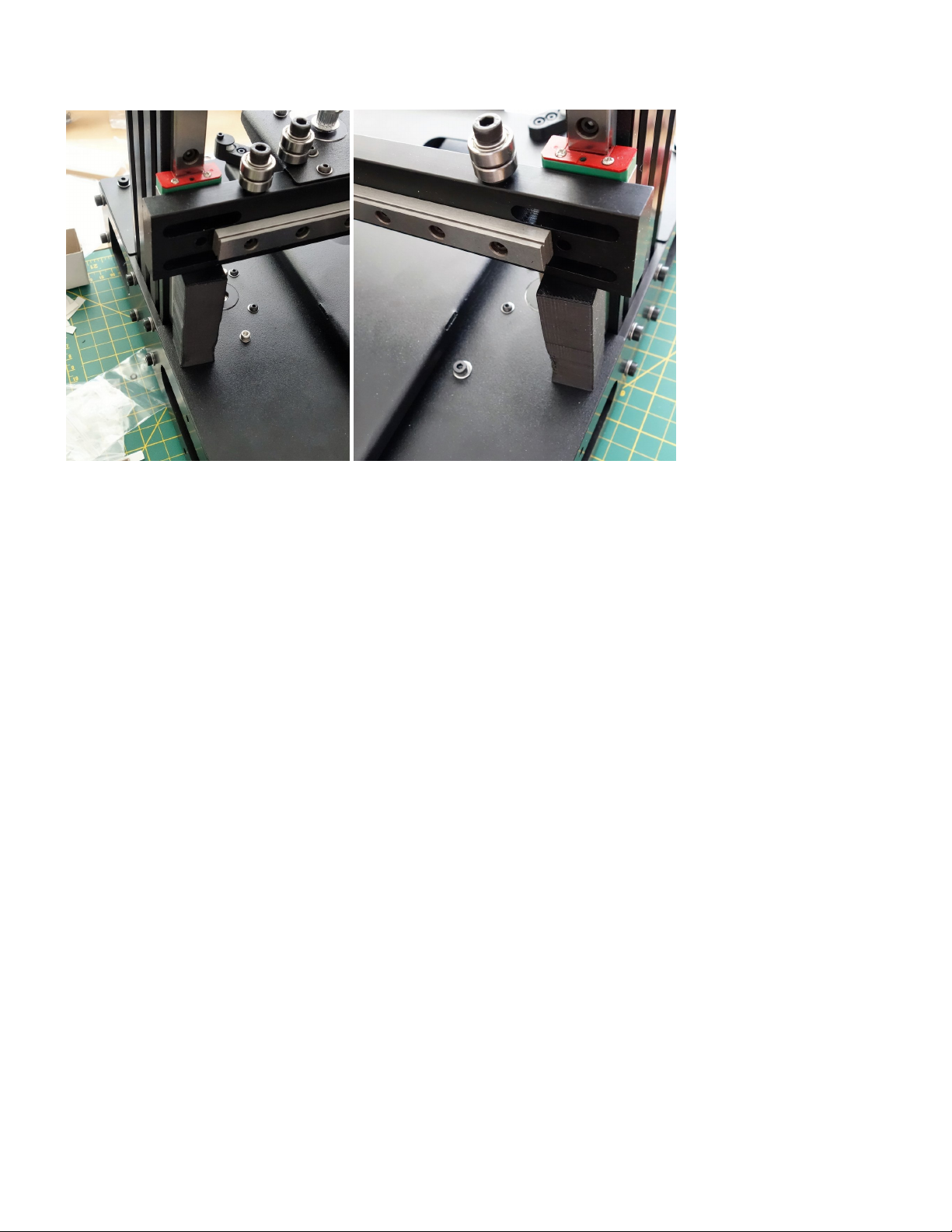
7. Using two equal length spacers, lower the axis so it is supported on both sides and equal height
above the base.
Page 42 of 151
Page 45
Maker's Tool Works MTW Create Assembly Guide - 1
8. Tighten the four button head screws on the left, and then the M3 screws with the O-Rings on the right,
do not over tighten them, they need to be just snug.
9. Lift the axis to the top of it’s motion and tighten the screws holding the slotted side of the top
crossbar.
Page 43 of 151
Page 46
Maker's Tool Works MTW Create Assembly Guide - 1
Installing the Lead Screws
Preparing the Lead Nuts
Parts Required
• 2 – Lead Nuts
• 6 – M3 × 10 SHCS
• 6 – M3 Nut
• 2 – Lead Screw
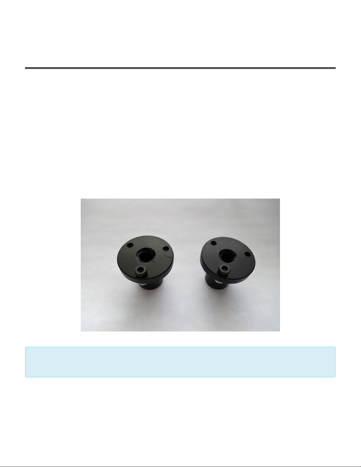
1. Install one M3 × 10 SHCS into each hole on each Lead Nut with the screw head towards the flat side
of the nut. Secure with *one M3 Nut.
Note the photo above only shows one screw, but you should add one screw in each hole,
so three per lead nut.
*
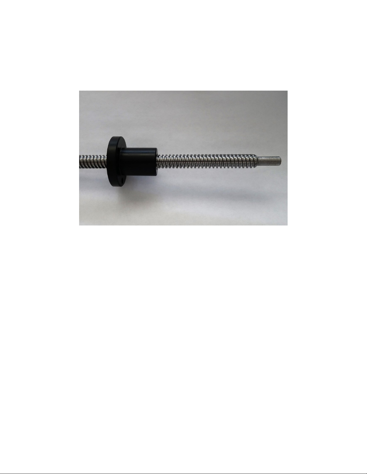
2. Install each assembled Lead Nut onto the Lead Screw and make sure that you can turn the nut with
just one finger and thumb.
If you cannot easily turn the nut you will need to chuck the Lead Screw into a drill, add no more than
Page 44 of 151
Page 47
Maker's Tool Works MTW Create Assembly Guide - 1
a drop of lithium grease to the threads and run the nut back and forth a couple dozen times, until it
becomes easy to turn with a single finger and thumb. Other than the initial drop of lithium grease
during the breaking in process, do NOT lubricate even if it still tight.
Then position the Lead Nut about 2” from the bottom of the screw.
Install the Couplers and Lead Screw
Parts Required
• 2 Helical Couplers
• Printed X Belt Spacer
• 2 – 4.5mm BBs. (steel balls)
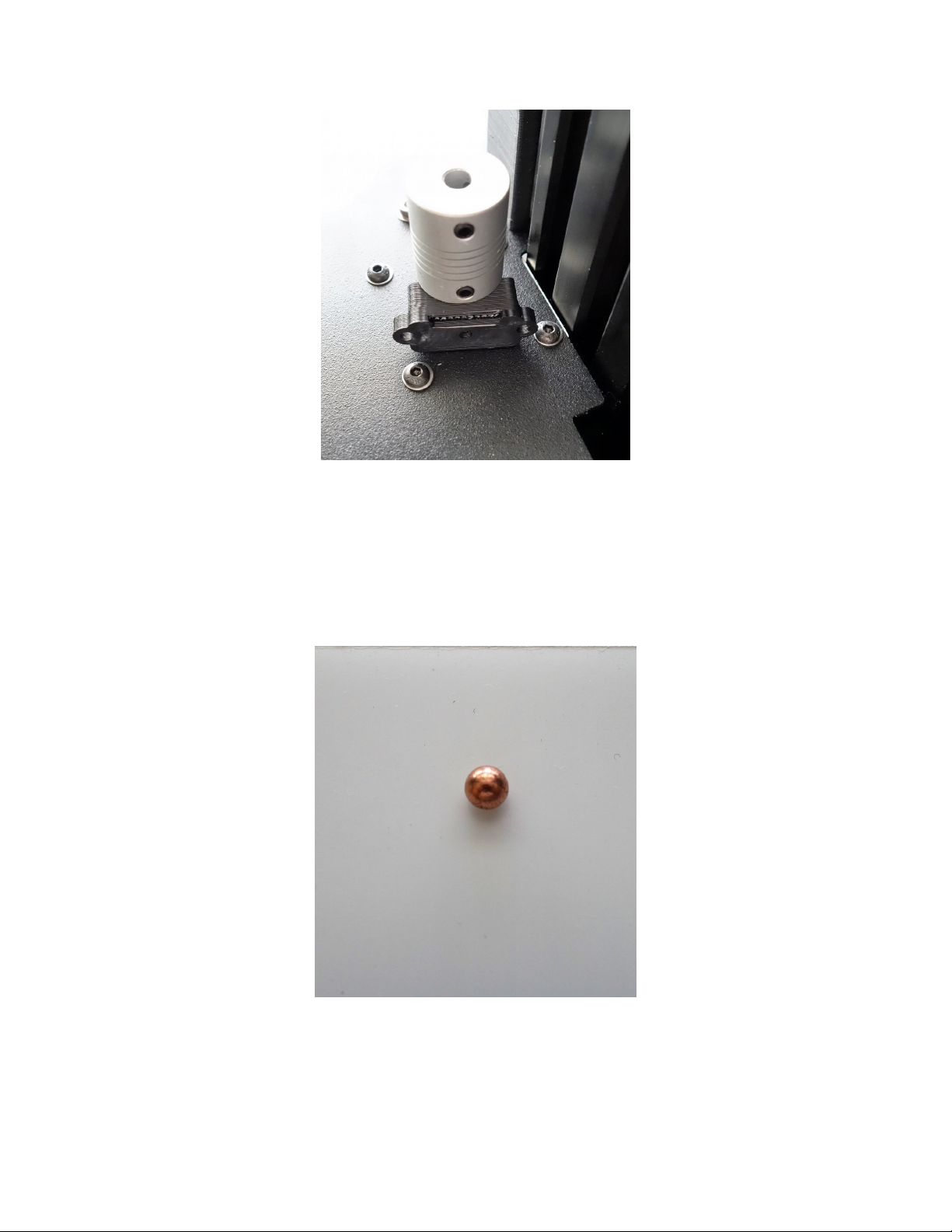
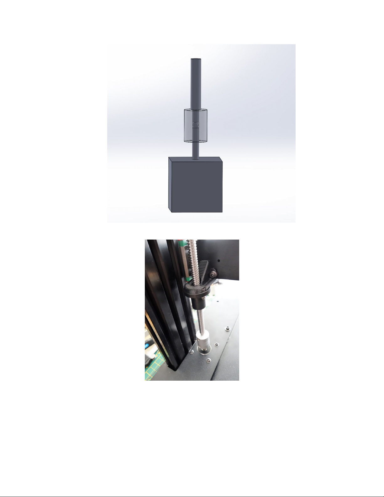
1. Install the Helical coupler onto each Z Motor Shaft. Use the X Belt Spacer on it’s side to properly set
the spacing above the top deck.
Page 45 of 151
Page 48
Maker's Tool Works MTW Create Assembly Guide - 1
2. Tighten the set screws, making sure one of them is against the flat of the motor shaft.
3. Set the X Belt Spacer aside until you install the X axis belt.
4. Put one BB into each helical coupler.
5. Install the Lead Screw so it is resting on the BB. Note the BB is critical for best print quality. We
include spares, so be sure to include one.
Page 46 of 151
Page 49
Maker's Tool Works MTW Create Assembly Guide - 1
6. Tighten the set screws on the Helical Coupler.
Page 47 of 151
Page 50
Maker's Tool Works MTW Create Assembly Guide - 1
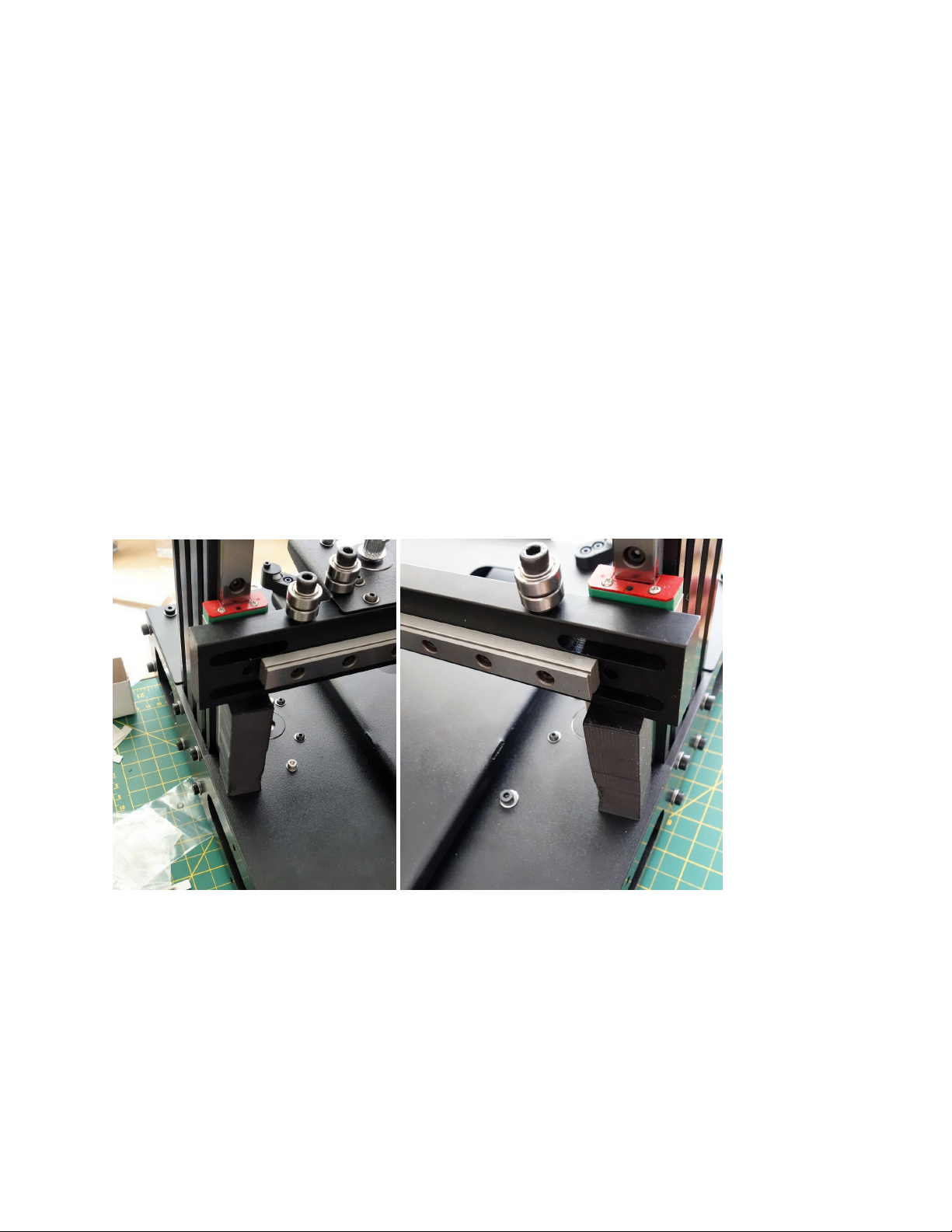
Leveling the X axis and the Lead Nuts
Parts Requried
• Calipers or the 2 spacers used in the* Installing the X axis* section
1. Rest the X axis on the Lead Nuts, ensure that the nuts are locked into the Lead Nut Adapters
2. Using the calipers, measure the distance from the Top deck plate to the X axis, by the Z extrusions.
3. Turn each leadscrew manually, to get an equal distance on both sides.
4. If you do not have calipers, rest the X axis on the 2 spacers you have used in the previous section of
the guide.
5. Using two equal length spacers, lower the axis so it is supported on both sides and equal height
above the base.
6. Ensuring the nuts are locked into the Lead Nut Adapters, turn each leadscrew manually, until you feel
equal weight on both spacers when you try to move them.
Page 48 of 151
Page 51
Maker's Tool Works MTW Create Assembly Guide - 1
Installing the X Carriage
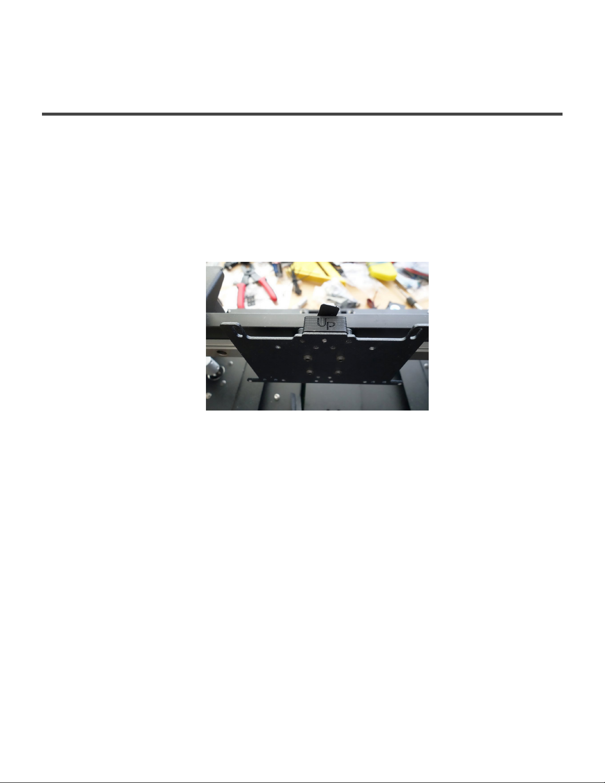
Mounting the X Carriage Plate
Parts Required
• 4 – M3 × 6 BHCS
• X Carriage Plate
1. Mount the X Carriage Plate to the X Rail using four M3 × 6 BHCS. Do not use washers.
Installing the X Belt
Parts Required
• X Belt Spacer
• X Belt Clip
• 1 – M3 × 16 SHCS
• 2 – M3 × 6 BHCS
• 1 – Timing belt
1. Insert belt into X Belt Spacer as shown
Page 49 of 151
Page 52
Maker's Tool Works MTW Create Assembly Guide - 1
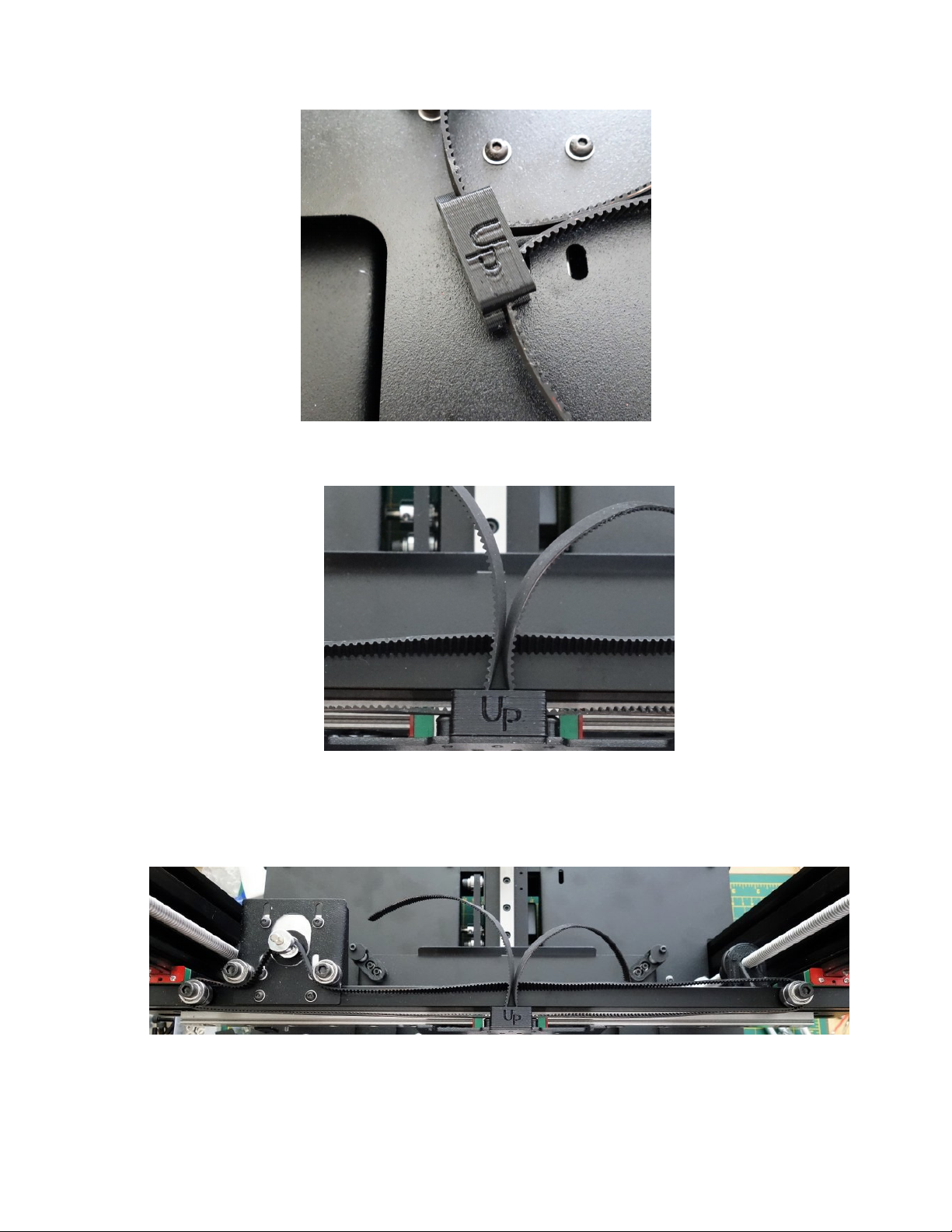
2. Install the X Belt Spacer on the X Carriage Plate with two M3 × 6 BHCS
3. Install the X Belt Clip using M3 × 16 SHCS
4. Route the belt as shown
5. Push on one side of the X Belt Clip to hold the belt. Pull on the other side to tension.
Page 50 of 151
Page 53
Maker's Tool Works MTW Create Assembly Guide - 1
6. Tighten X Belt Clip. The clip may bend when properly tightened. That is normal and will not cause a
problem.
Page 51 of 151
Page 54
Maker's Tool Works MTW Create Assembly Guide - 1
Extruder Assembly and Installation
Assemble the Extruder
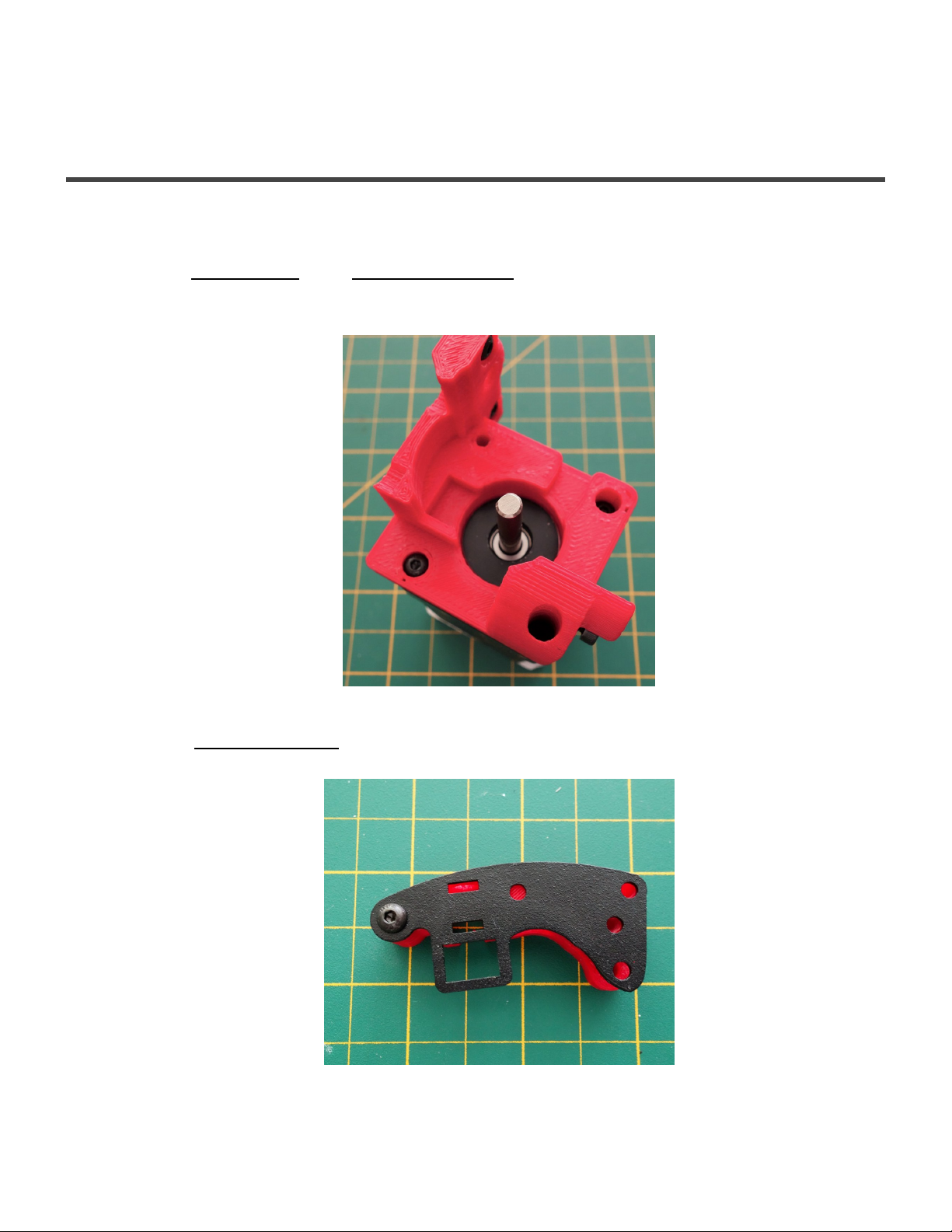
1. Install the Stepper Motor to the printed extruder body with three M3 × 6 BHCS. Do not install the
screw in the top back position. This will be the hole for later attachment of the lever arm to the
extruder body.
2. Attach the Extruder Arm Plate with one M3 × 6 BHCS or a self tapping screw to the right side of the
printed piece
Page 52 of 151
Page 55
Maker's Tool Works MTW Create Assembly Guide - 1
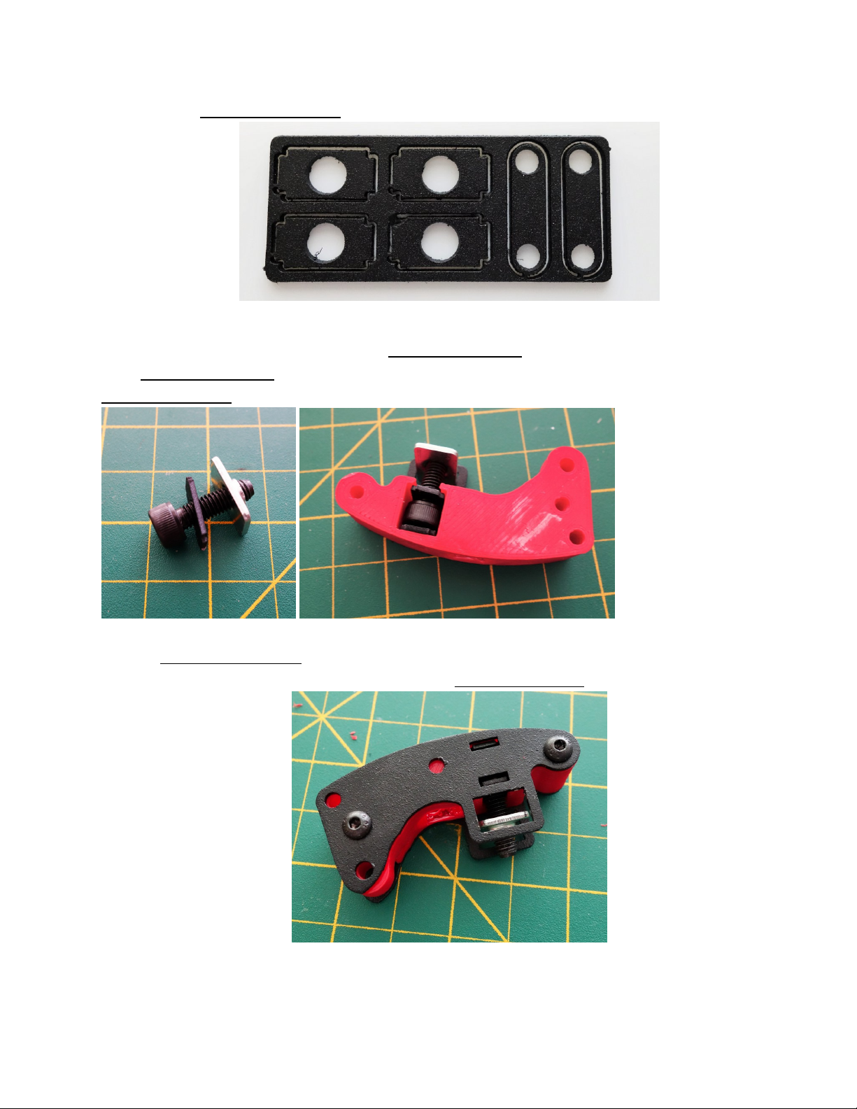
3. Break out two Extruder Arm Inserts from the plate shown below
4. Assemble on the M5 × 16 SHCS with one Extruder Arm Insert and T-nut, and then together with the
other Extruder Arm Insert insert into the printed arm, making sure to get them into the slots cut in the
Extruder Arm Plate
5. The two Extruder Arm Inserts are held in place with the slots cut into the metal side pieces. Use two
M3 × 6 BHCS or self tapping screws to attach the Extruder Arm Plate to the printed part.
Page 53 of 151
Page 56
Maker's Tool Works MTW Create Assembly Guide - 1
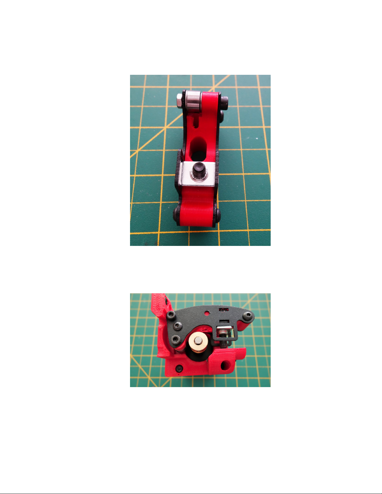
6. Install the small bearing using two M3 Washer to center the bearing to the small filament guide hole in
the printed plastic part. Use a M3×18 SHCS screw and nut to secure the bearing and washers as
shown.
7. Install the completed lever arm to the extruder body with a M3×30 SHCS screw using a washer next
to the screw head. Use thread lock on this screw. Tighten but leave loose enough so the lever arm
can move. Do not install the brass hob yet.
8. Install the spring then the brass hob onto the stepper motor shaft. You will need to squeeze the lever
arm down to do this step.
Page 54 of 151
Page 57
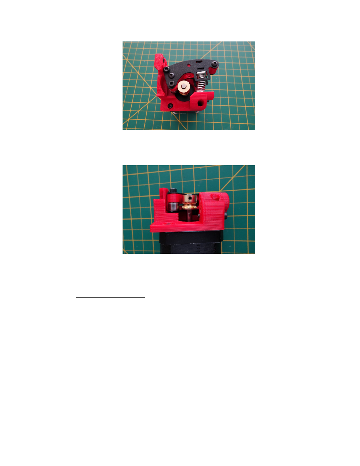
Maker's Tool Works MTW Create Assembly Guide - 1
9. Align the brass hob to the filament hole in the arm, and tighten the grub screw against the flat of the
shaft.
Extruder Installation
1. Inspect the Aluminum hot end block for any debris or burrs in the hotend mounting holes. If there is
any, gently clean with a sharp implement, or a file. Use the E3D hotend heatsink to test fit.
Page 55 of 151
Page 58
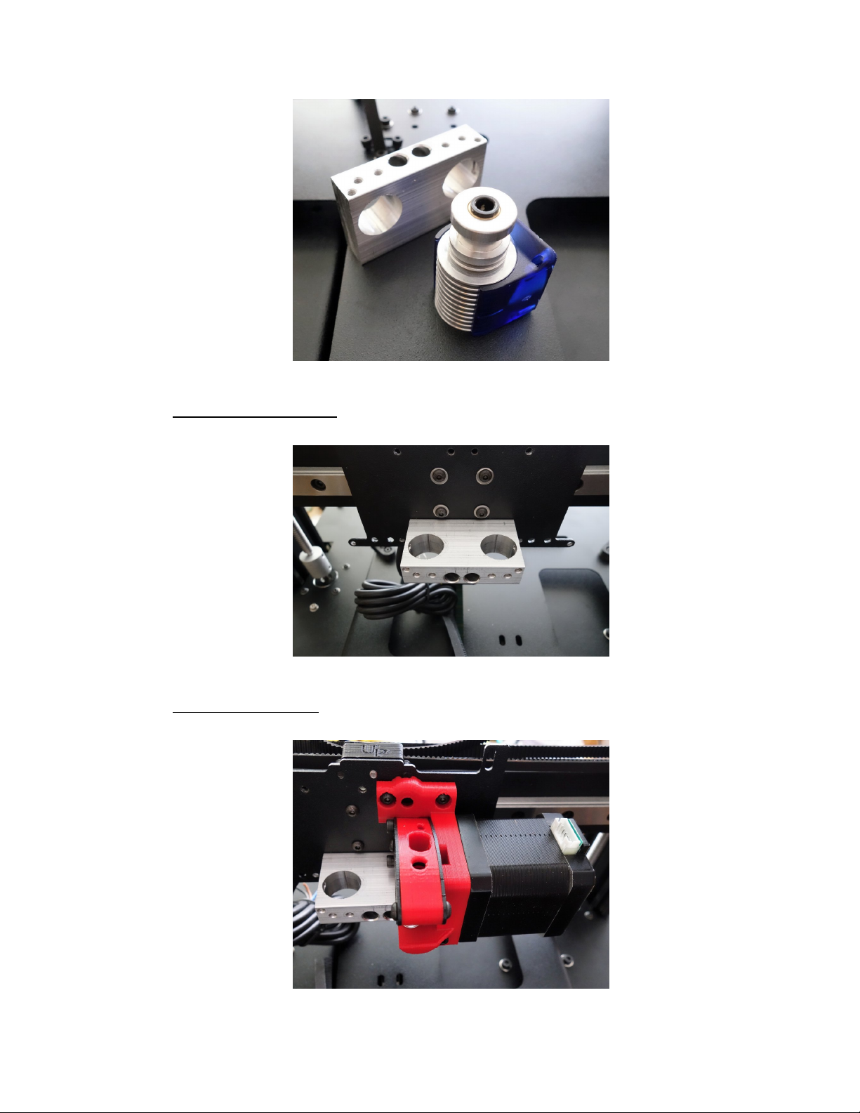
Maker's Tool Works MTW Create Assembly Guide - 1
2. Install the Aluminum hot end block to the carriage with two M3 × 10 SHCS inserted into the deep
holes that are center front of the block.
3. Install the printed extruder body to the carriage with two M3 × 6 BHCS screws. Also attach it to the
Hotend Block with a M3×18 SHCS
Page 56 of 151
Page 59

Maker's Tool Works MTW Create Assembly Guide - 1
Hotend Assembly and Installation
Hotend Assembly
For the assembly of the E3D V6 Hotend either follow the steps below or use the
documentation and this excellent video tutorial:
*
The E3D V6 thermistor leads are very fragile and need to be handled with care, as it is not
!
covered by our warranty.
1. Install the nozzle into the heatblock using a washer to set a gap. Do not screw it in flush with the
block. Note the block orientation.
Page 57 of 151
Page 60
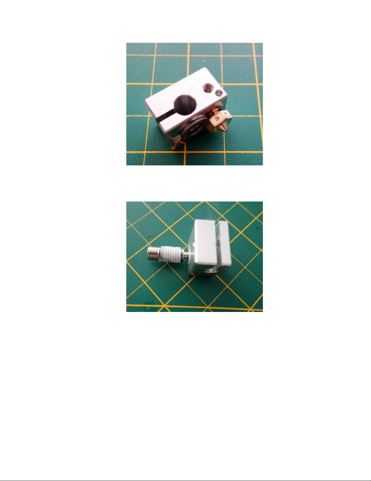
Maker's Tool Works MTW Create Assembly Guide - 1
2. Cover the threads on the heatbreak with the supplied thermal compound, and install the short end into
the heatblock.
Page 58 of 151
Page 61
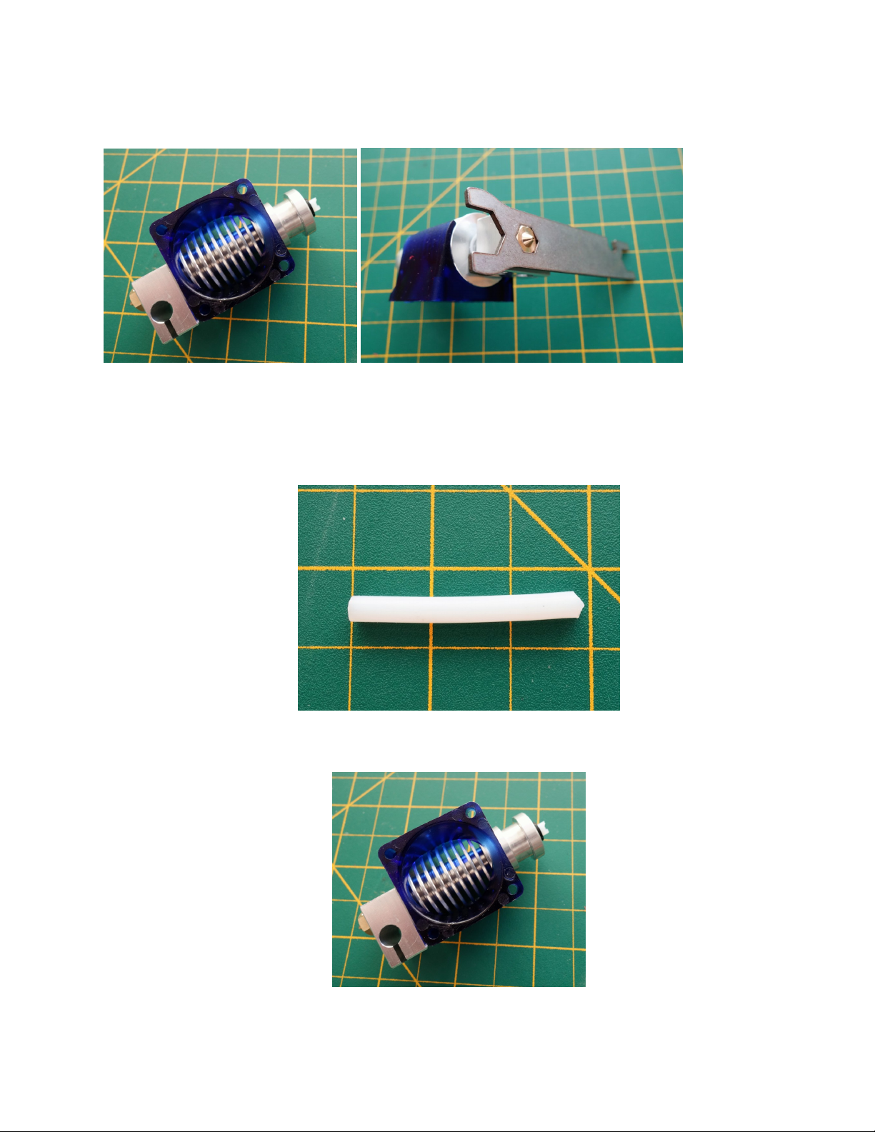
Maker's Tool Works MTW Create Assembly Guide - 1
3. Install the heatblock assembly into the heatsink, tighten it slightly using the supplied wrench. Do not
over tighten, that can damage the heatbreak.
4. Cut the white PTFE tube to about 36-37mm, ensure the cut on one end is straight, and cut the other
end as shown.
This will ensure that the filament does not try to bow out as much from the hob to the hotend causing
a jam.
5. Install the tube into the hotend
Page 59 of 151
Page 62
Maker's Tool Works MTW Create Assembly Guide - 1
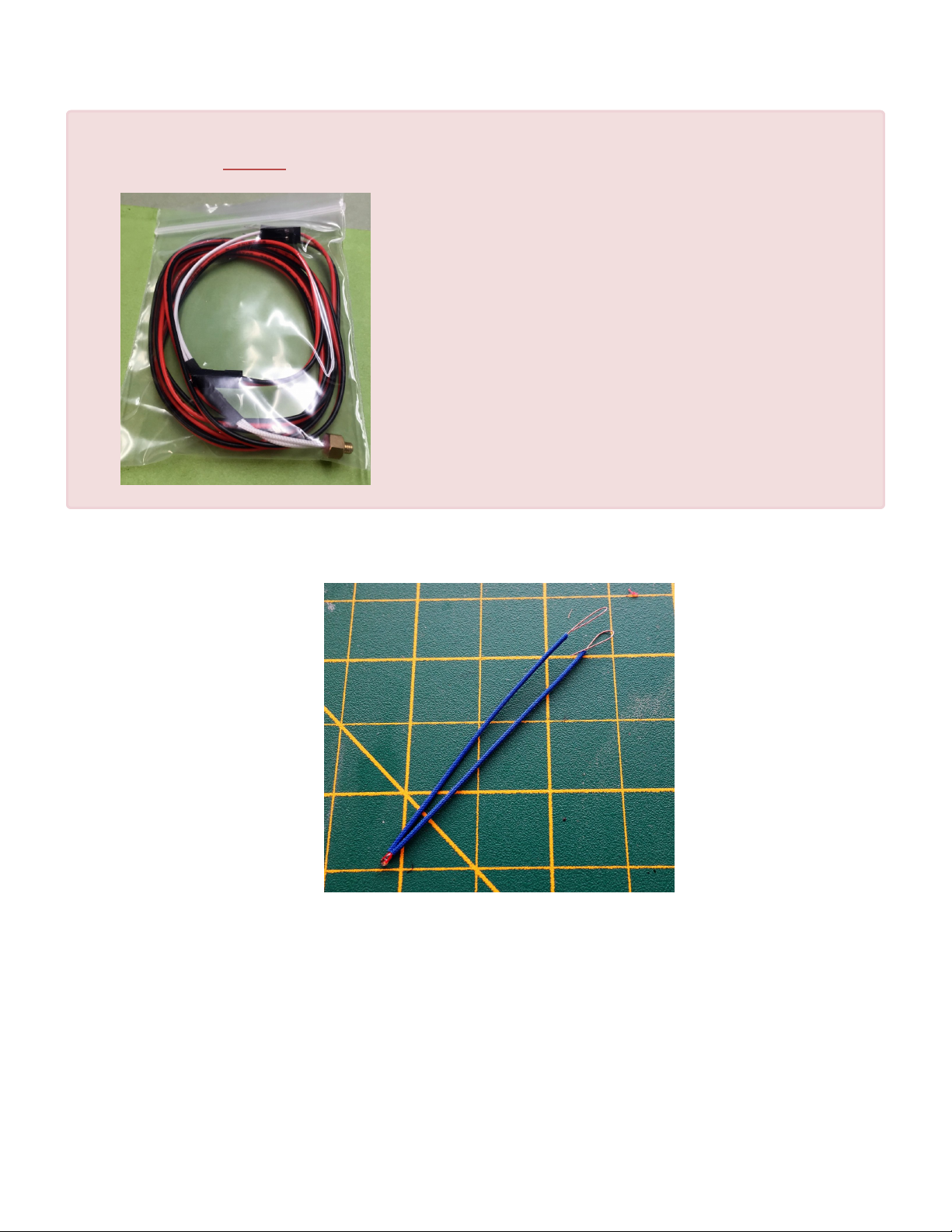
Your kit may have come with the pictured below, stud type of thermistor,
!
if so, skip to step 12, and screw it in place of the thermistor retention screw shown in step
12.
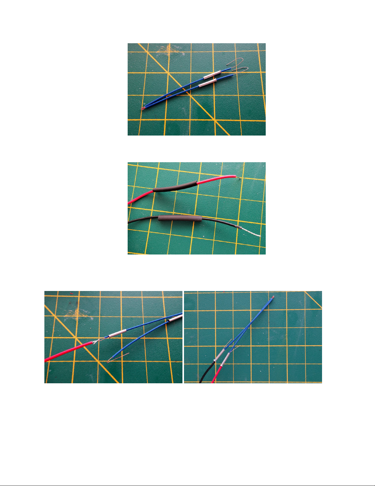
6. Cut the supplied blue fiberglass insulation into two equal pieces, and slide them on the thermistor
leads.
7. Slide the ferrules on the leads, and bend the exposed leads as shown.
Page 60 of 151
Page 63
Maker's Tool Works MTW Create Assembly Guide - 1
8. Cut the heatshrink in two, and slide the pieces on the supplied thermistor extension wire
9. Hook the extension wire with the thermistor leads, and slide the ferrule over it. Make sure the ferrule
goes a bit over the extension wire insulation. Trim, or bend over the excess leads.
10. Make sure the fiberglass insulation is flush with the thermistor glass bead, and no lead is exposed.
Using a crimping tool, or pliers, crimp the ferules.
Page 61 of 151
Page 64
Maker's Tool Works MTW Create Assembly Guide - 1
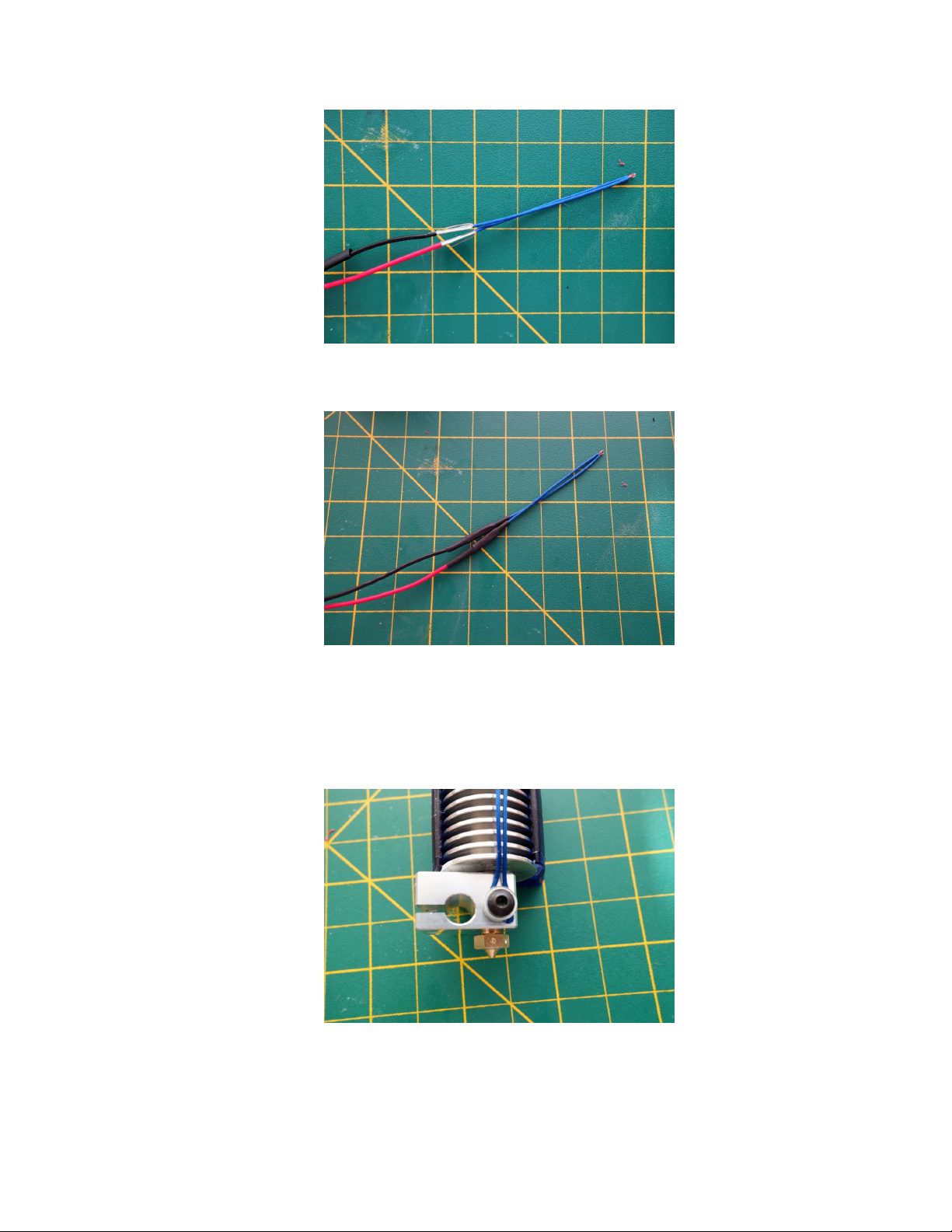
11. Cover the ferrules with heatshrink, and shrink it using a heat gun, or hair dryer set to hot.
12. Carefully insert the thermistor into the smaller hole, on the side of the heatblock, and secure it in
place using the supplied BH 3×4 screw and washer. Flip the washer with the rounded side toward the
insulation. Tighten just enough to hold it securely, over tightening can crush the insulation, expose
and short the thermistor leads.
13. Insert the heating cartridge into the heatblock, and secure it with the supplied BH 3×10.
Page 62 of 151
Page 65
Maker's Tool Works MTW Create Assembly Guide - 1
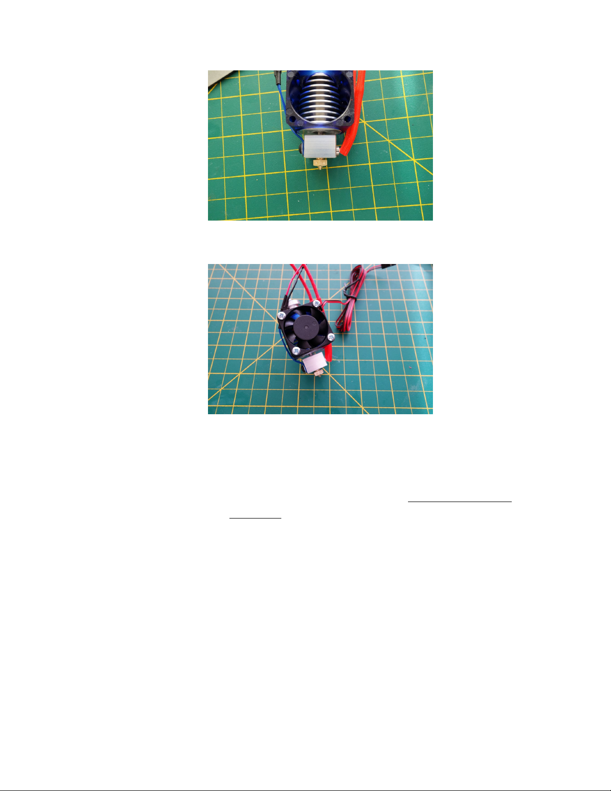
14. Install the 30mm fan, sticker toward the heatsink
15. Install the hotend from the bottom of the hotend block. You may have to raise the Z to have enough
room to do this step.
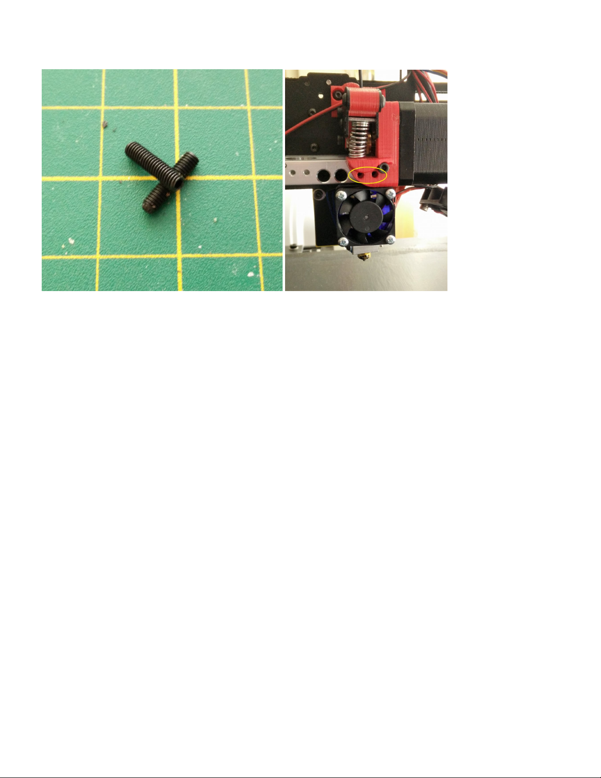
16. The hotend block has two holes in the front, as shown below, for two M3-12mm set screws to secure
the hotend in place. Tighten the set screws so the screw hits the Hotend groove.
Page 63 of 151
Page 66
Maker's Tool Works MTW Create Assembly Guide - 1
17. With the hotend and the lever arm in place you can now adjust the hob to be centered in the filament
path. Look down the small filament hole on top of the lever arm and adjust to location of the hob then
tighten.
Page 64 of 151
Page 67
Maker's Tool Works MTW Create Assembly Guide - 1
Installing the ABL Sensor
Installing the ABL Sensor
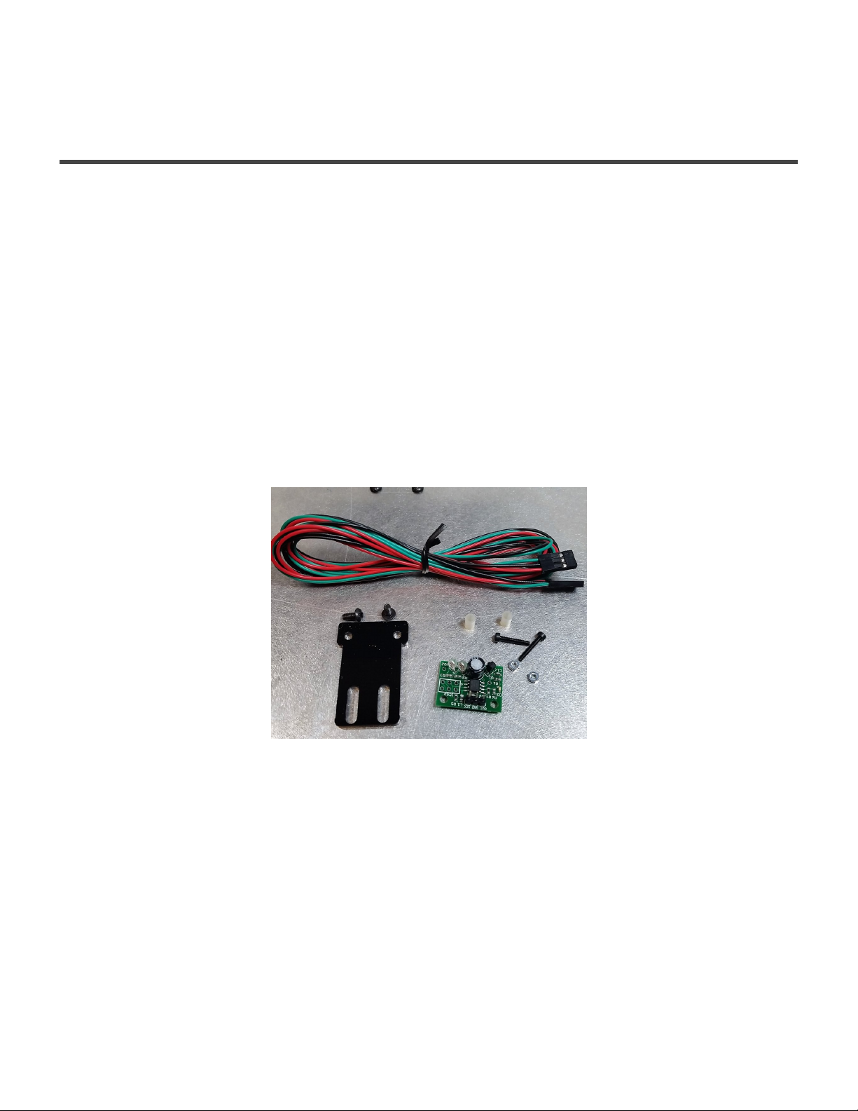
Parts Required
• - 2 M3 × 6 BHCS
• - 2 M2 × 12 SHCS
• - 2 M2 Nut
• - 2 M3 Washer
• - 2 mini standoffs
• - 1 Acrylic ABL Sensor Mount Plate
• - 1 ABL Sensor
• - 1 Sensor wire
1. Attach the sensor to the acrylic mount using two M2 × 12 SHCS, two M2 Nuts, and the mini standoffs
between the plate and the board as shown above.
Page 65 of 151
Page 68
Maker's Tool Works MTW Create Assembly Guide - 1
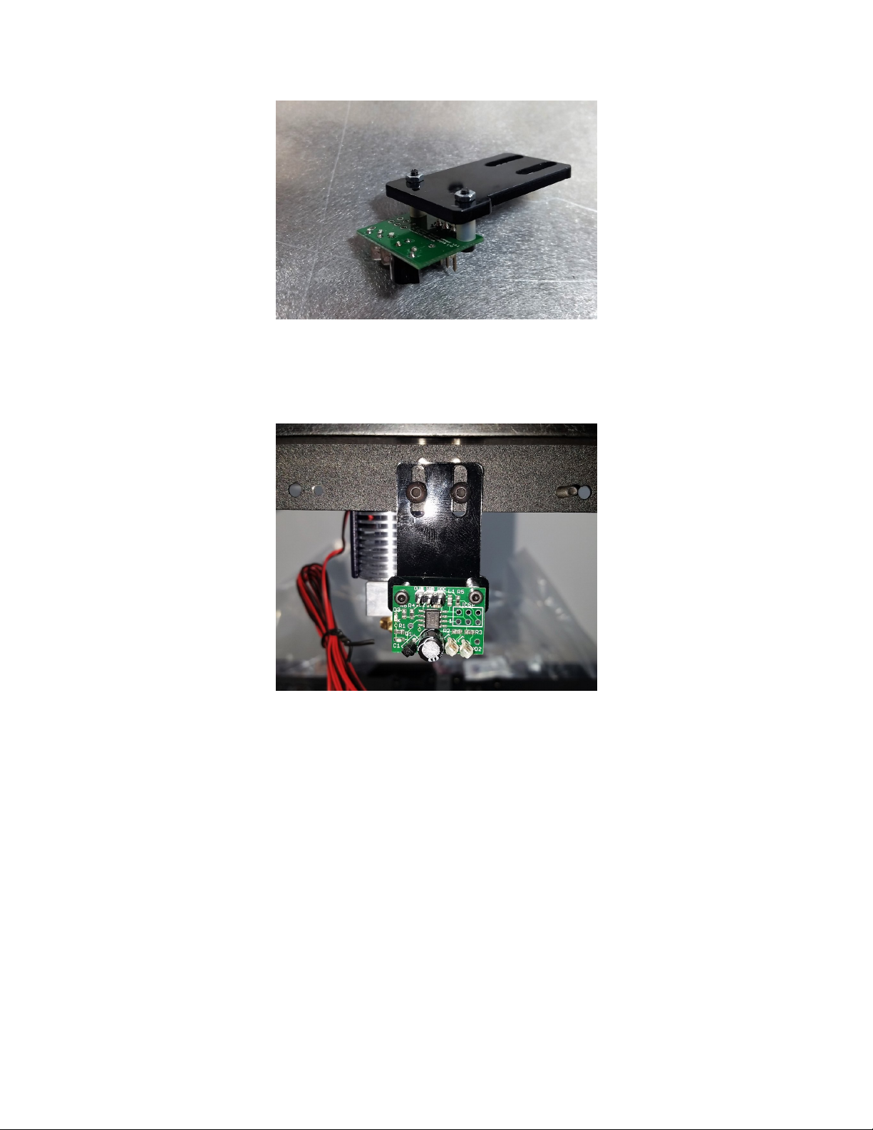
2. Attach the plate and sensor to the back of the X Carriage Plate, using the two M3 × 6 BHCS, and two
M3 Washer as shown above.
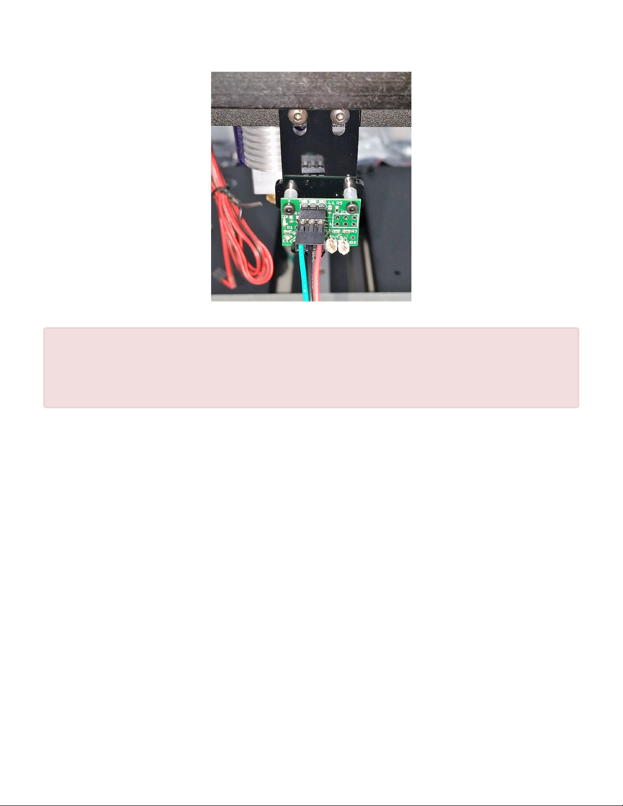
3. Connect the sensor wire. Note the orientation of the connector, the green wire should be on the OUT
pin, and the red wire on the VCC pin.
Page 66 of 151
Page 69
Maker's Tool Works MTW Create Assembly Guide - 1
Verify 3 times that your sensor wire is connected as outlined above. Failure to follow
!
these directions will destroy the sensor and can also possibly damage your RAMBo
board. Warranty is not available for the sensor being improperly connected or any
subsequent damage done to the board.
Page 67 of 151
Page 70
Maker's Tool Works MTW Create Assembly Guide - 1
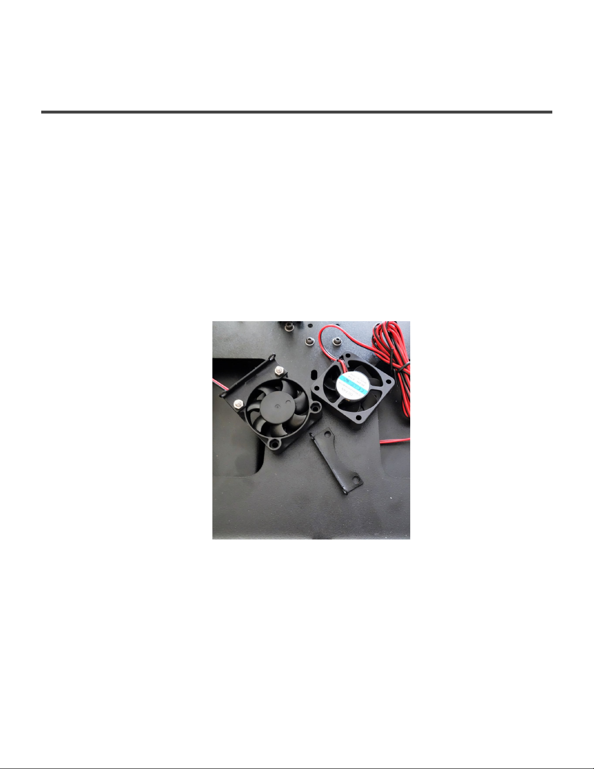
Installing the Fans and Endstops
Installing the 40mm Fans
Parts required
• 2 – M3 × 6 BHCS
• 4 – M3 × 22 SHCS/ zip ties
• 4 – M3 Nut
• 2 – Fan Mounts
• 2 – 40mm Fans
1. Install the fan on the Fan Mount, using two M3 × 22 SHCS and two M3 Nut or two zipties, repeat with
the other fan.
2. Install the Fan Mount on the X Carriage Plate as shown. Repeat on the other side.
Page 68 of 151
Page 71

Maker's Tool Works MTW Create Assembly Guide - 1
Installing the Endstops
Parts required
• 2 – Endstop switches.
• 2 – Endstop wires
• 3 – M2×15 SHCS (Needs checking
• 3 – M2 nuts
• 2 – M3 × 6 BHCS
• 1 – M3 × 10 SHCS
• 1 – M5 × 10 SHCS
• 1 – X Endstop Mount Plate
• 1 – Y printed Endstop Mount
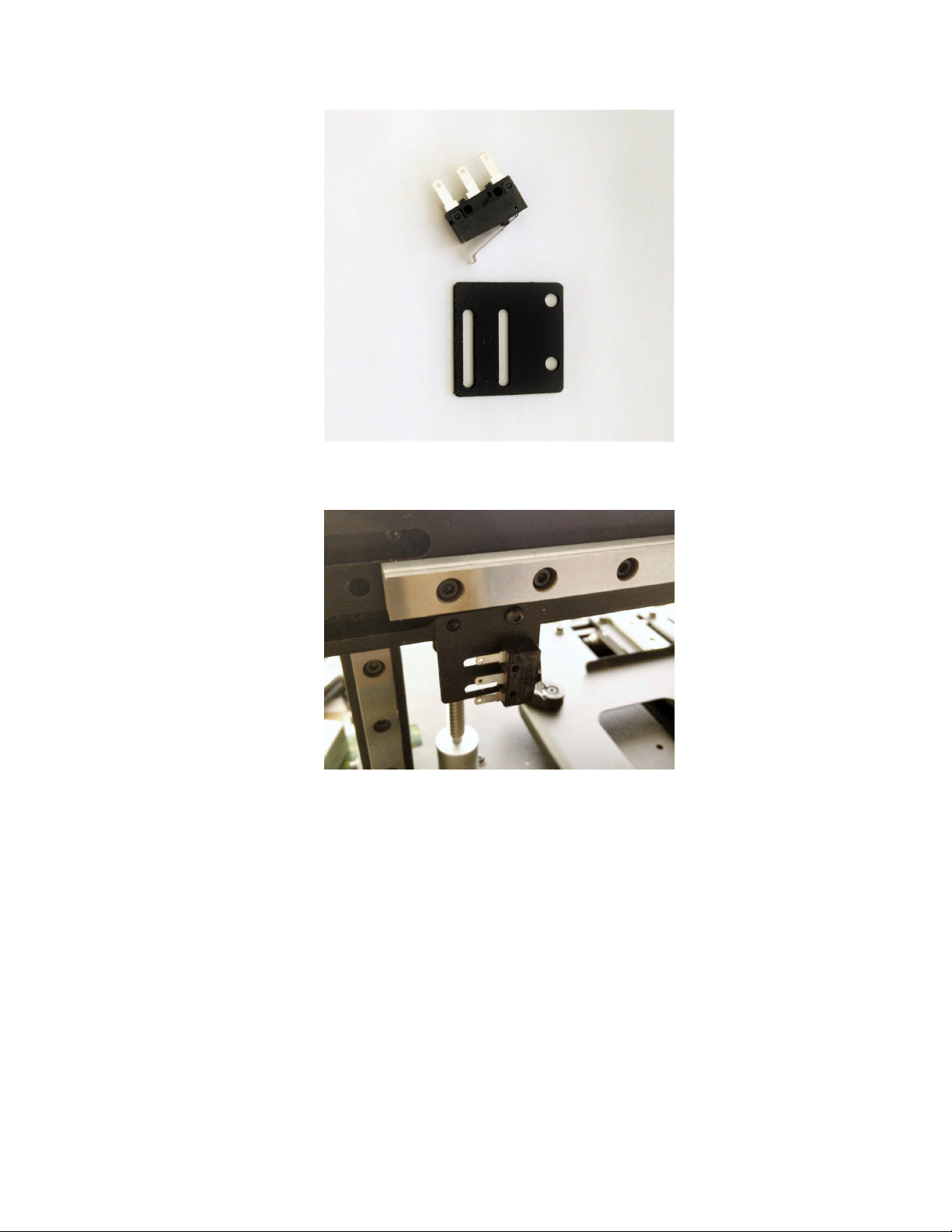
1. Install the endstop switch on the mounting plate using two M2×15 SHCS and two M2 nuts. You will
adjust the endstop position, later in the guide.
Page 69 of 151
Page 72
Maker's Tool Works MTW Create Assembly Guide - 1
2. Attach the X endstop mount plate, using two M3 × 6 BHCS
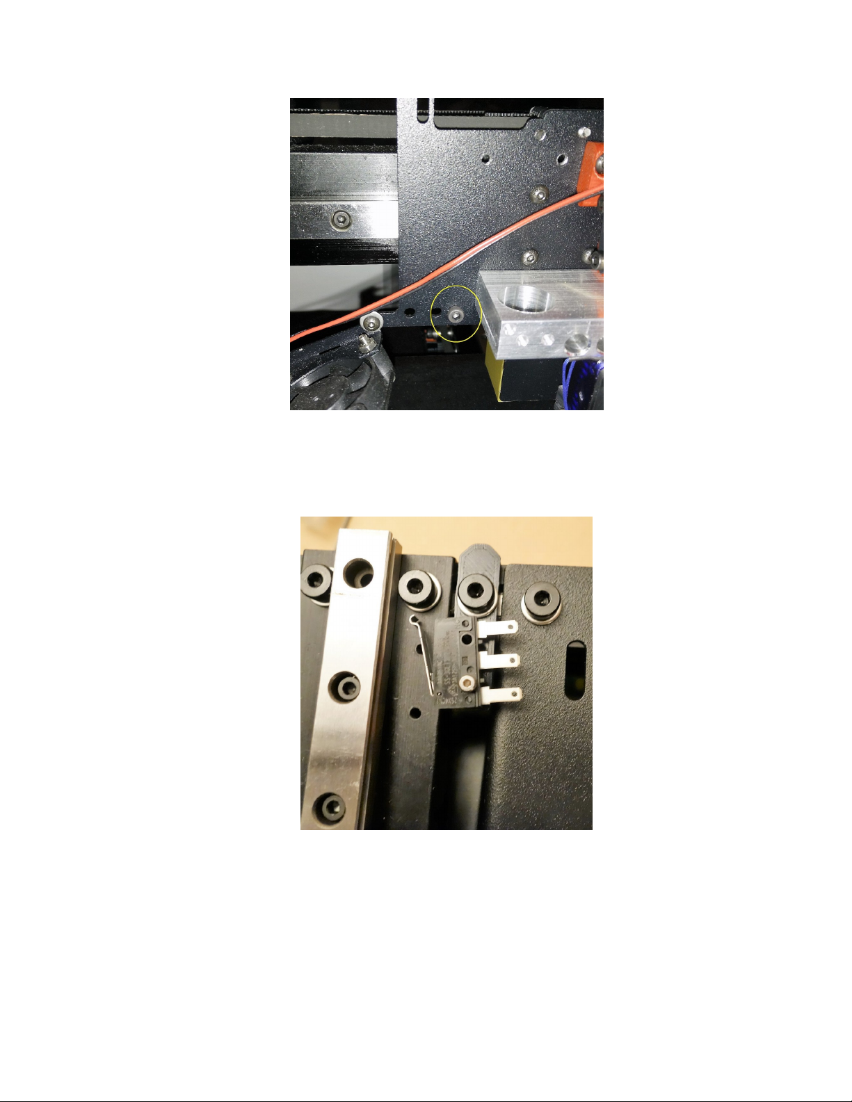
3. Install a M3 × 10 SHCS into the tapped hole on the X Carriage Plate as shown below
Page 70 of 151
Page 73
Maker's Tool Works MTW Create Assembly Guide - 1
4. Attach the endstop switch to the printed mount, using one M2×15 SHCS and one M2 nut, then attach
the mount to the M5 Post Install Nut in the back extrusion, using M5 × 10 SHCS. You will adjust the
endstop angle later in the guide.
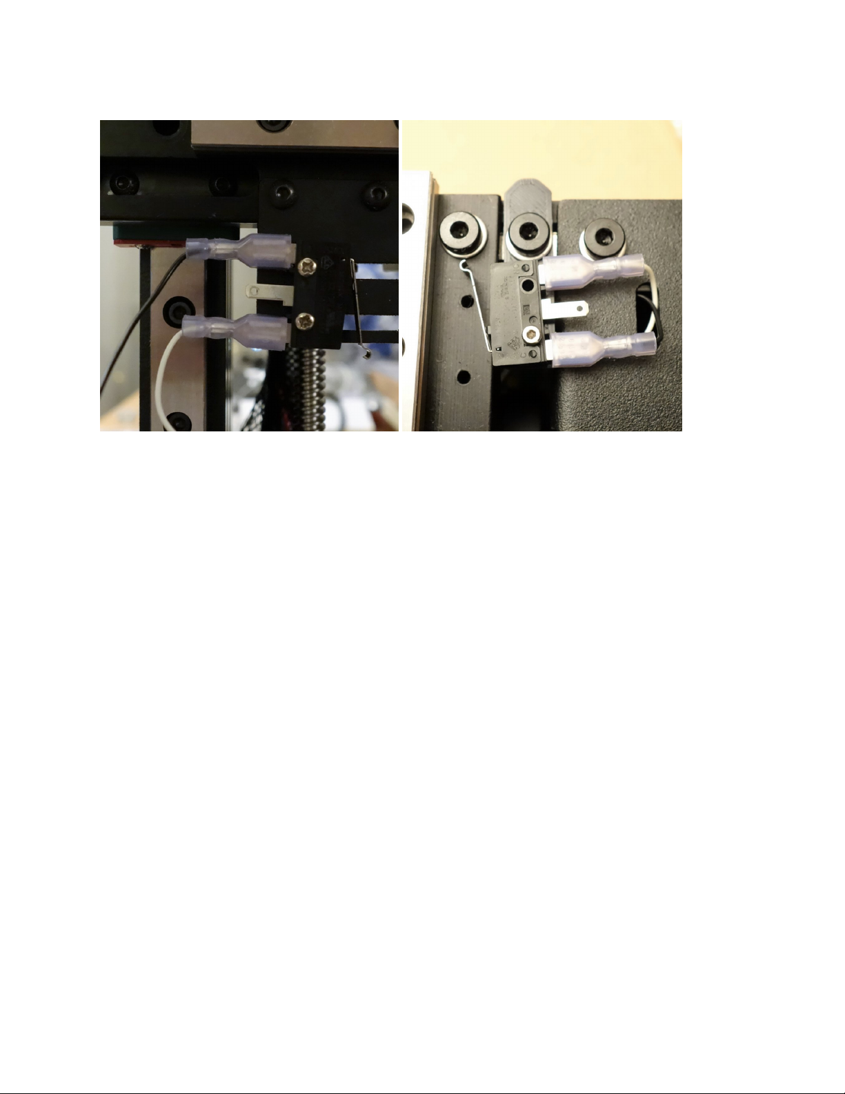
5. The endstop wires are provided with the RAMBo board, they are black and white, with spade
connectors on one end, and a keyed connector on the other end. Connect them to the switch outside
Page 71 of 151
Page 74
Maker's Tool Works MTW Create Assembly Guide - 1
terminals. Since there is no polarity they can go on either terminal, except for the middle one.
Page 72 of 151
Page 75
Maker's Tool Works MTW Create Assembly Guide - 1
Tightening the belts
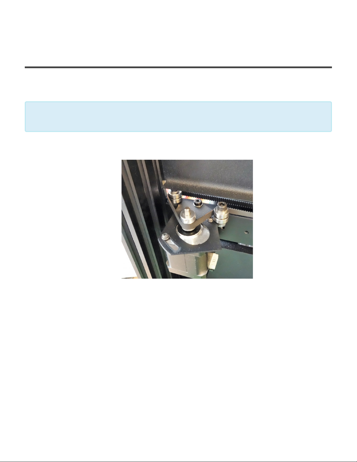
Tightening the belts
The gauge the belt tightness, pluck it like a guitar string. If you get a thud, the belt is loose,
if you get a high note its too tight. Aim for a low bass note (D)
*
1. To tighten the Y belt, loosen the two button head screws, turn the motor down to the desired
tightness, and tighten the screws.
2. Test the belt, if you get the low bass note, trim the belt leaving at least 40mm of the belt.
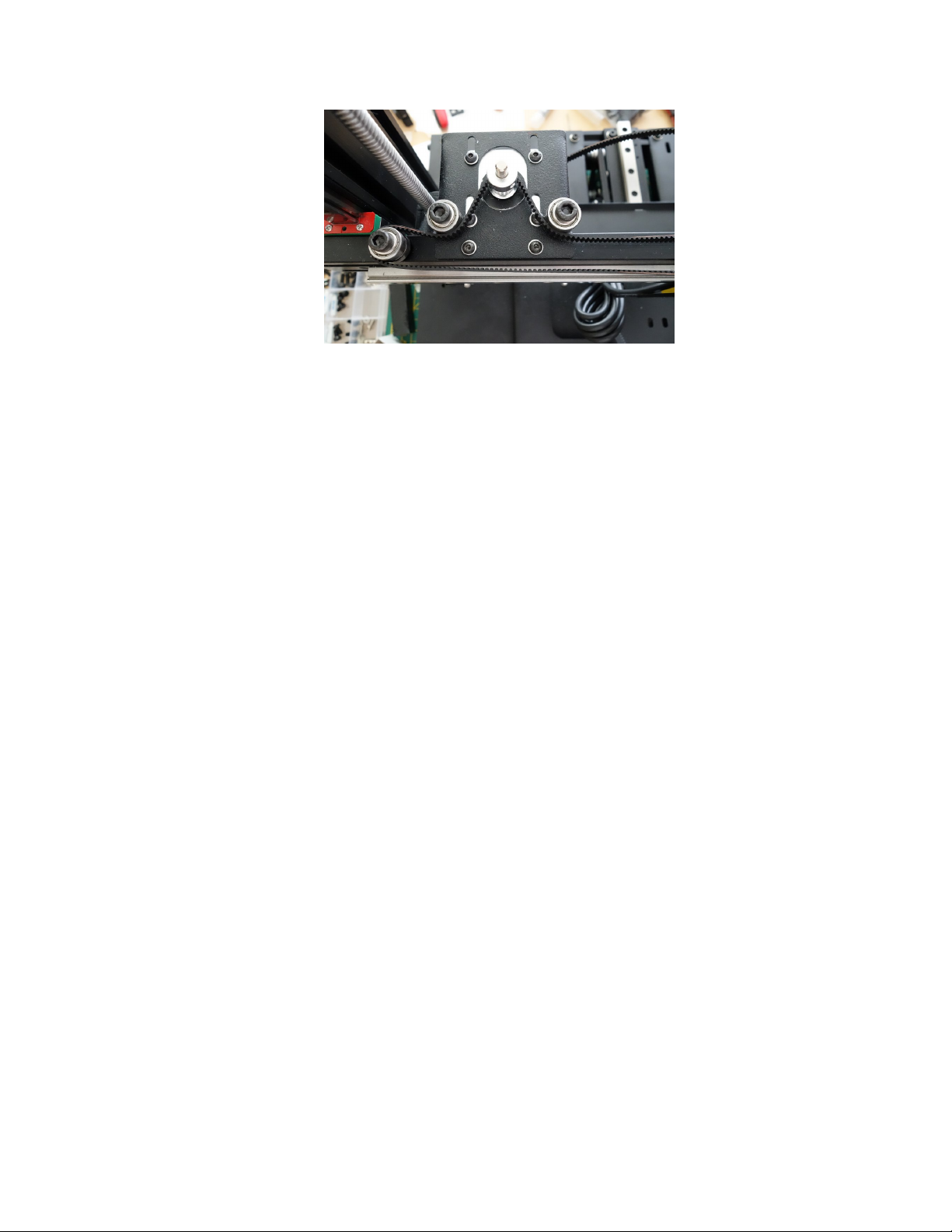
3. To tighten the X belt, loosen the four button head screws, push the motor toward the back to the
desired tightness, and tighten the screws.
Page 73 of 151
Page 76
Maker's Tool Works MTW Create Assembly Guide - 1
4. Test the belt, if you get the low bass note, trim the belt leaving at least 40mm of the belt.
Page 74 of 151
Page 77
Maker's Tool Works MTW Create Assembly Guide - 1
Installing the Glass and Bed Heater
Installing the Glass and Heater
Parts Required
• 1 – Kapton Bed Heater
• 1 – Heatspreader plate
• 1 – Glass
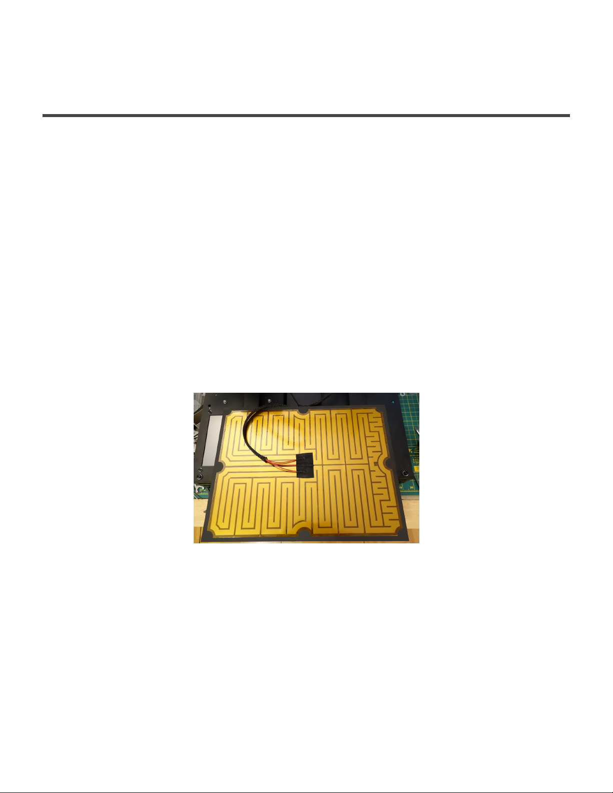
1. Align and center the Heater on the Heat Spreader, with the paper backing down towards the
aluminum. Use scotch tape or similar along one edge to temporarily hold it in place.
2. Fold the heater back and peel a corner off the backing on the edge you taped in place to expose the
adhesive.
3. Slowly apply the Heater to the Spreader, peeling off the backing as you smooth out the heater.
4. Use about 240mm of Wire Loom to cover the heater wires. Place the heater, with the heater facing
down, and the spreader facing up, and route the cables down through the circular hole on the right
hand side. Secure the wires with a ziptie to the two slots of the plate.
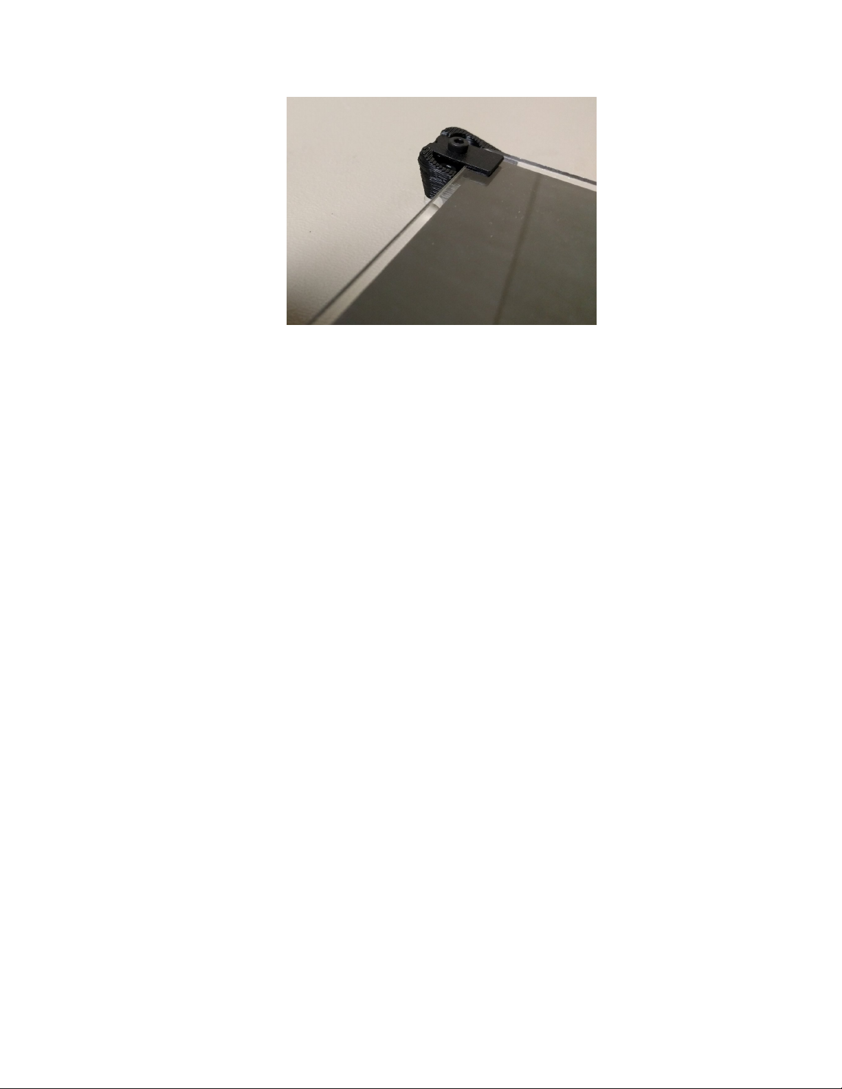
5. Place the glass, and secure it with the clip plates, using M3-18 SHCS.
Page 75 of 151
Page 78
Maker's Tool Works MTW Create Assembly Guide - 1
Page 76 of 151
Page 79

Maker's Tool Works MTW Create Assembly Guide - 1
Wiring
Page 77 of 151
Page 80
Maker's Tool Works MTW Create Assembly Guide - 1
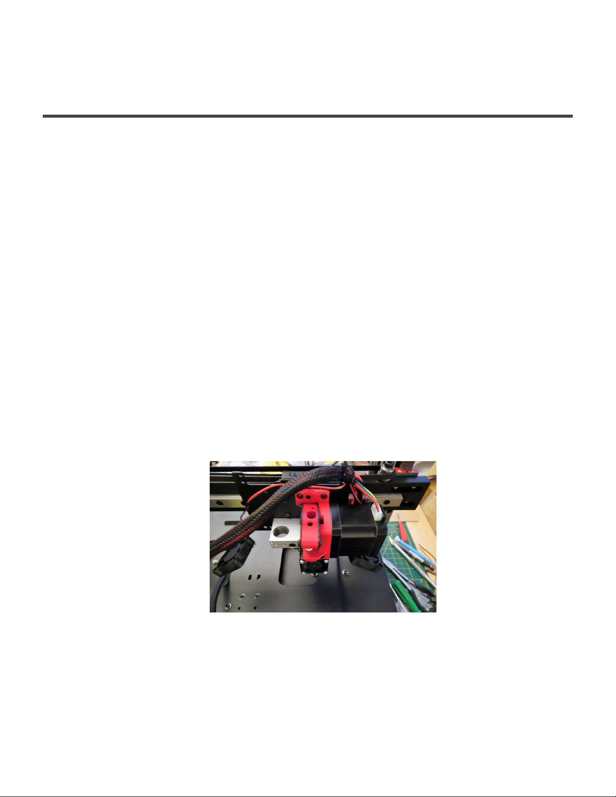
External Wire Management
External Wire Management
1. For easier identification of each wire at later steps of the wiring, using tape, and a marker, label:
• each fan wire,
• extruder motor wire,
• thermistor wire,
• heater cartridge wire,
• ABL sensor wire
• X motor wire,
• X Endstop wire,
2. Connect the two long stepper cables that came with the kit to the Extruder motor, and X motor. The
short cables will be used for the other three motors, at a later stage.
3. Cut a 90cm long piece of the provided braided cable sleeving. It should be long enough to allow full Z
and X travel of the extruder.
4. Collect all the cables listed in step 1, except for the X motor and endstop, and put them into the cable
sleeving.
Use a zip tie to attach the bundle to a slot on top of the X carriage
5. Insert the other side of the bundle, into a cutout on the left side of the Top Deck Left, by the Z
extrusion.
Page 78 of 151
Page 81
Maker's Tool Works MTW Create Assembly Guide - 1
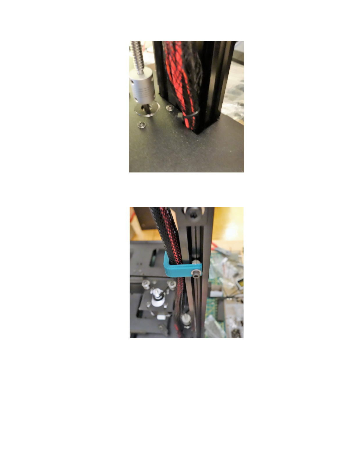
6. Using a M3 Post Install Nut, a M3 × 10 SHCS, and a printed clip, secure the bundle to the back of the
left Z extrusion, about 2” from the top.
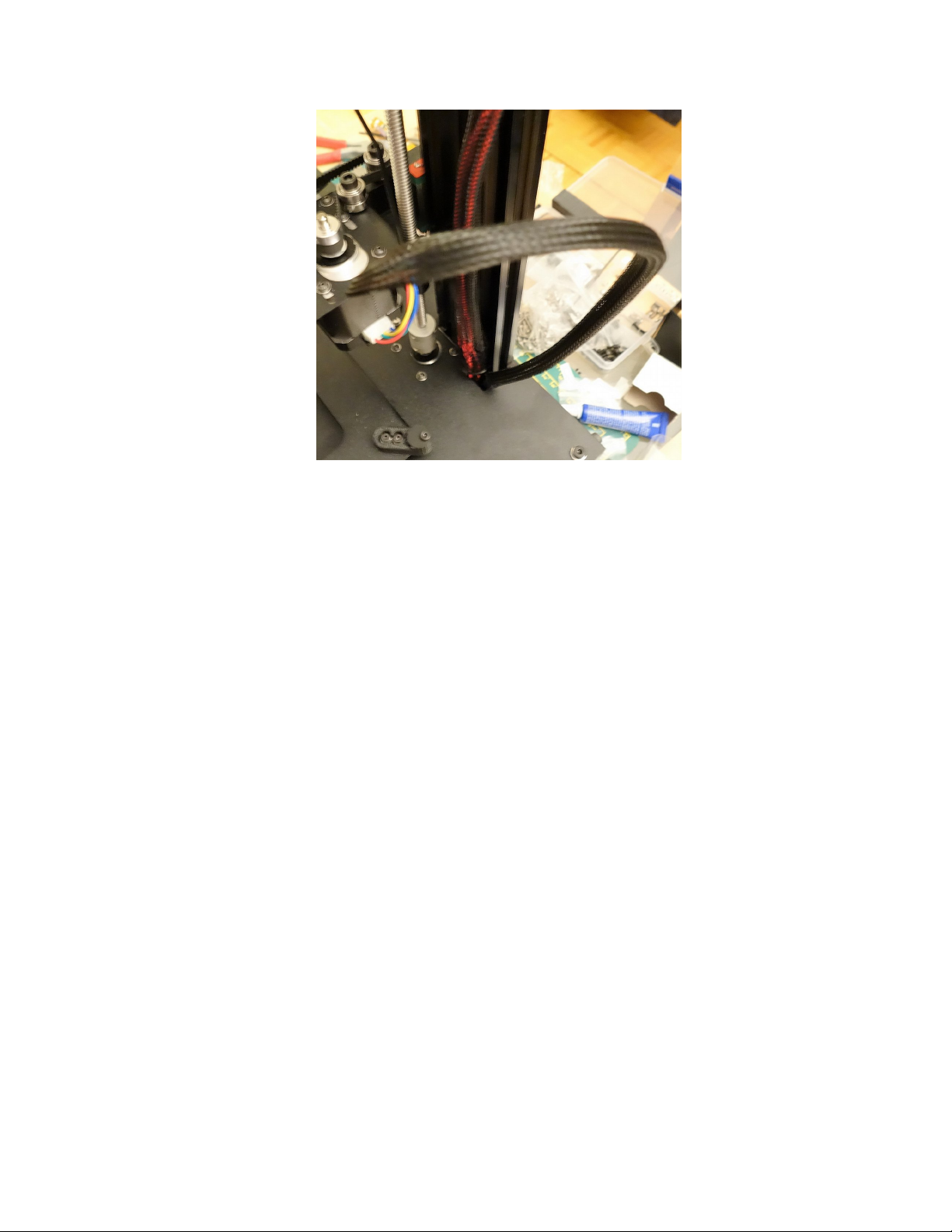
7. Cut a ~55cm long piece of the wire loom, and use it on the X motor and endstop wires.
Ziptie one end to the X motor plate, and run the other end into the cutout on the Top Deck Left
Page 79 of 151
Page 82
Maker's Tool Works MTW Create Assembly Guide - 1
Page 80 of 151
Page 83
Maker's Tool Works MTW Create Assembly Guide - 1
IEC, PSU and LED
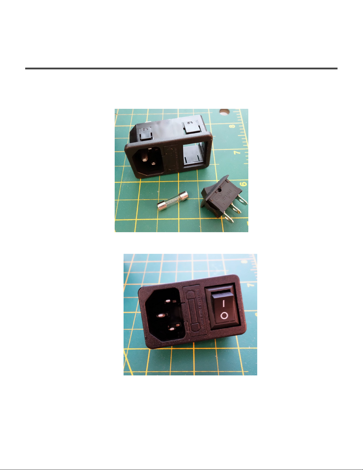
Flip the printer on its back.
IEC socket
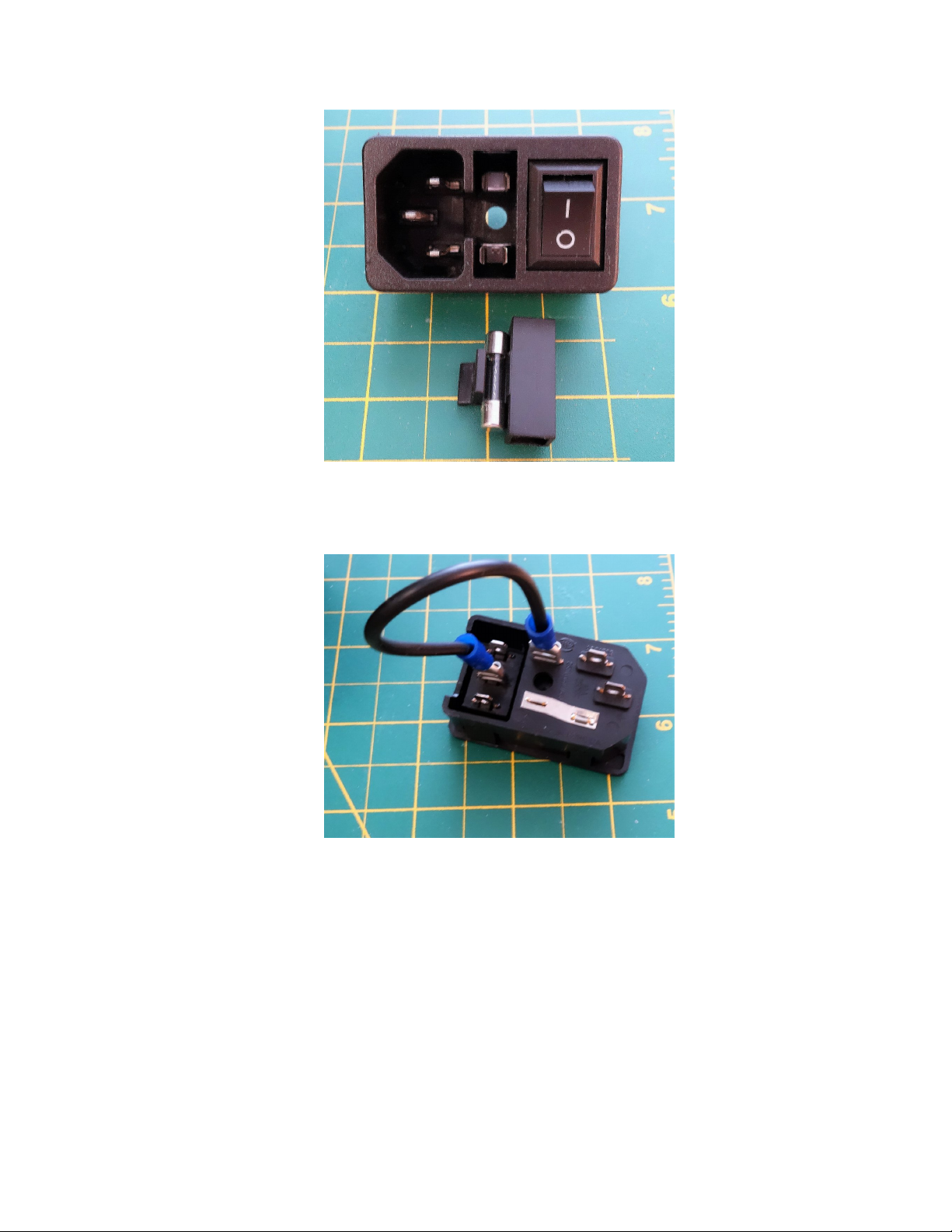
1. Install the switch into the IEC. Note the orientation of the switch, steps 3 and 4 depend on it.
2. Install the fuse into the IEC
Page 81 of 151
Page 84
Maker's Tool Works MTW Create Assembly Guide - 1
3. Connect the jumper wire as pictured below, if the connectors are loose, squeeze them a bit with
pliers.
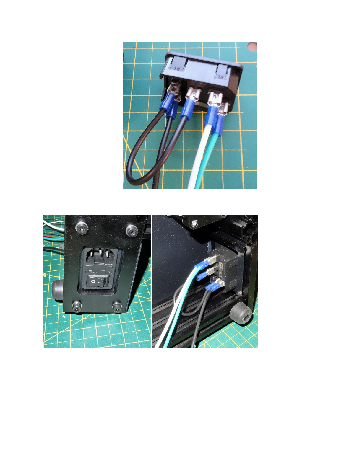
4. Connect the green, white and black wires.
Page 82 of 151
Page 85
Maker's Tool Works MTW Create Assembly Guide - 1
5. Insert the IEC with the wires into the IEC plate on the right side of the printer.
PSU Part 1
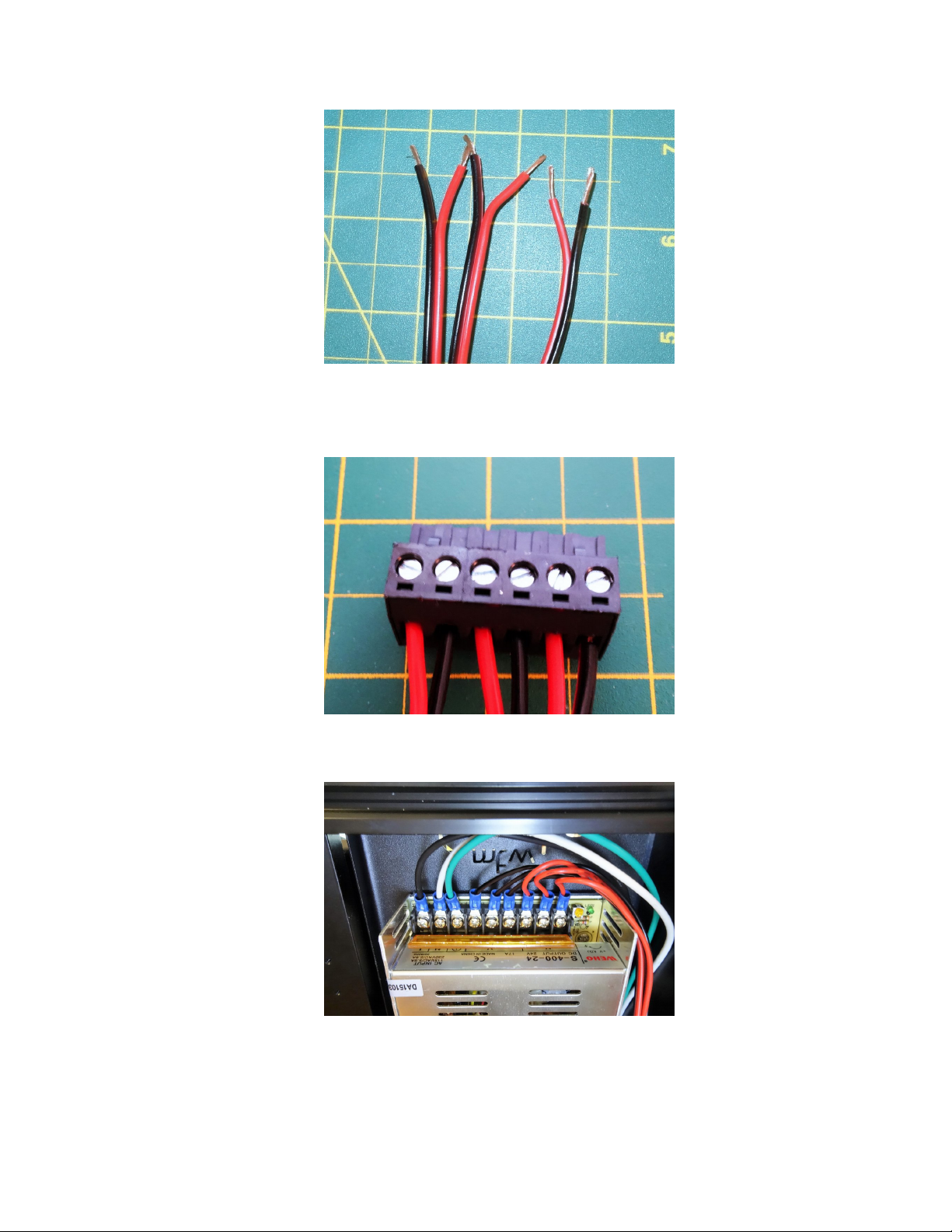
1. Strip and twist the cut ends of the three pairs of red and black wires.
Page 83 of 151
Page 86
Maker's Tool Works MTW Create Assembly Guide - 1
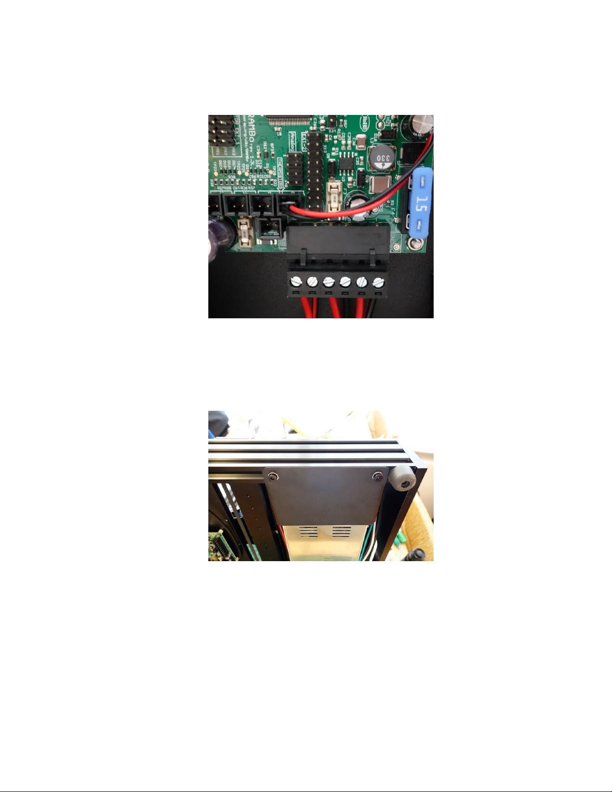
2. insert the wires into the power connector supplied with the RAMBo board, and tighten the terminals.
Note the polarity.
3. Attach the IEC and power wires to the PSU, as shown.
Page 84 of 151
Page 87
Maker's Tool Works MTW Create Assembly Guide - 1
LED
If you prefer a colored LED, you can substitute the white diffuser with a diffuser printed in
one of our premium translucent PLA colors. The stl for the diffuser is available here: diffuser
*
STL
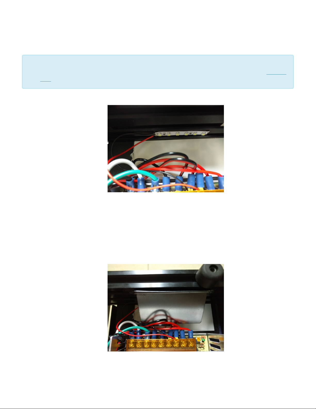
4. Glue the white diffuser plate to the deck plate as shown, using super glue.
5. Remove the adhesive backing paper off the led strip and stick it to the extrusion as shown in the step
above.
6. Wire the strip to the PSU as shown above. Note the red wires goes with the other reds, and black with
the blacks.
7. Attach the reflector plate to the extrusion, using two M3 Post Install Nut and two M3 × 6 BHCS
Page 85 of 151
Page 88
Maker's Tool Works MTW Create Assembly Guide - 1
PSU Part 2
8. Attach the power connector to the RAMBo board
9. Using 2 M5 Post Install Nut, 2 M5 × 8 SHCS and M5 Washer Attach the PSU wire cover to the bottom
of the front extrusion, covering the PSU terminals and wires. Attach the IEC cover in a similar manner
to the back extrusion covering the IEC terminals and wires,
You may hold on doing this step until you are satisfied with your wire arrangement.
Page 86 of 151
Page 89
Maker's Tool Works MTW Create Assembly Guide - 1
The kit comes with a number of printed clips for easier wire management. Those attach to
the deck plate with M3 screw and nut.
*
Page 87 of 151
Page 90
Maker's Tool Works MTW Create Assembly Guide - 1
RAMBo – Connecting steppers
For the connections for the Rambo controller please refer to the supplied paperwork
supplied with the Rambo. Changes to the controller may not have been updated to this
*
document.
Never plug or unplug the motor connector to the Rambo Controller with power turned on.
!
This can cause the motor driver chip to be damaged.
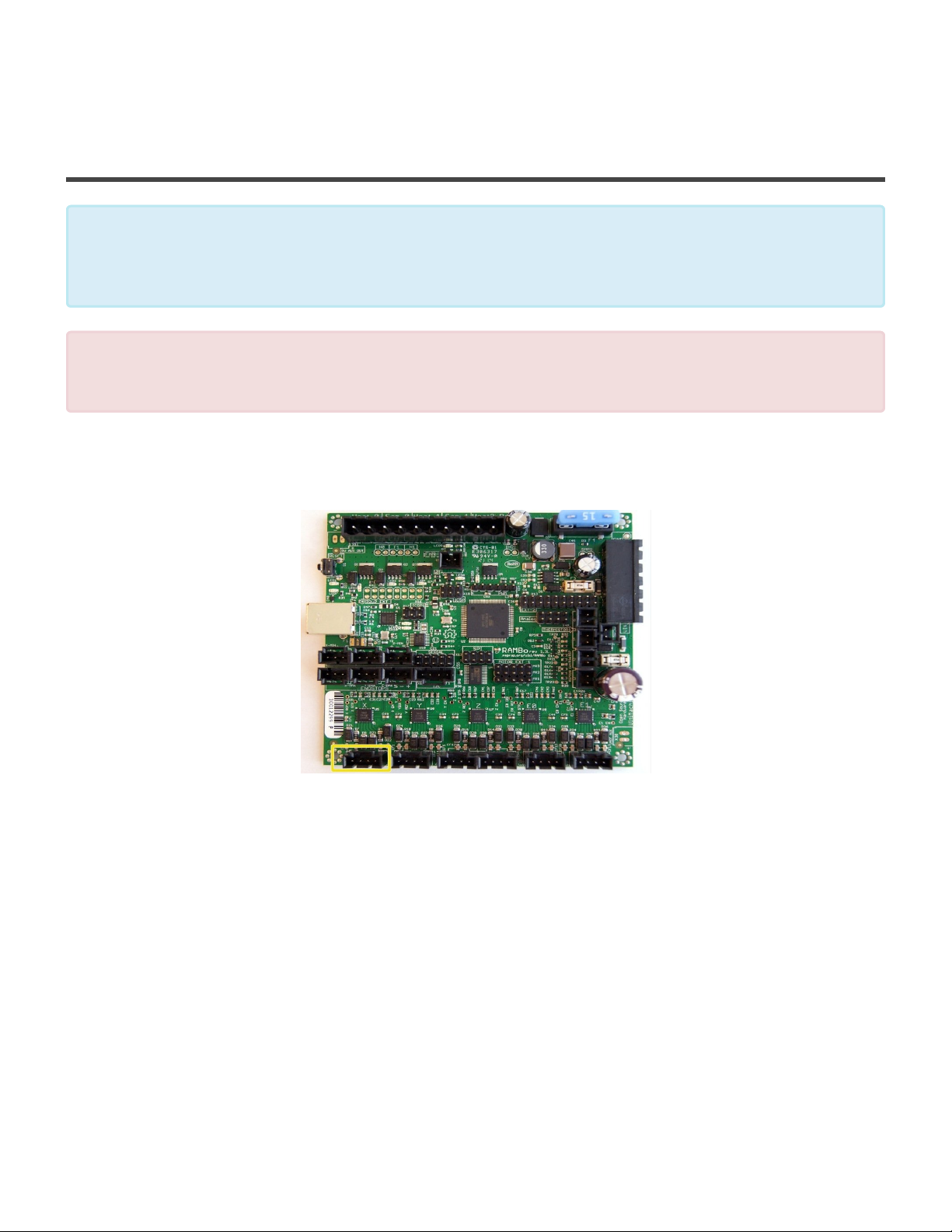
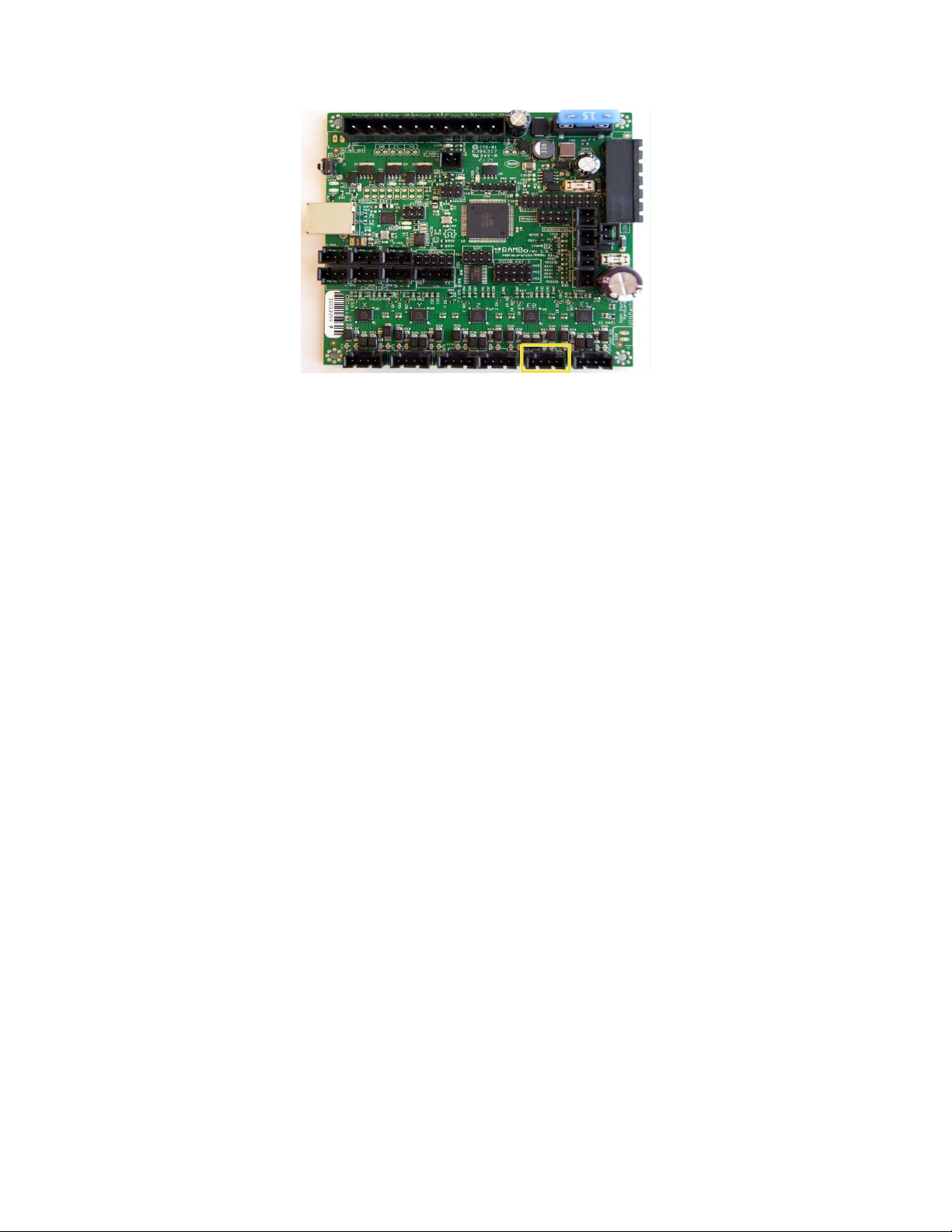
1. Attach the X Axis Stepper to the RAMBo X Driver plug, with the blue wire toward the USB port side, or
RasPi side.
2. Attach the Y Axis Stepper to the RAMBo Y Driver plug, oriented the same manner as the above.
Page 88 of 151
Page 91
Maker's Tool Works MTW Create Assembly Guide - 1
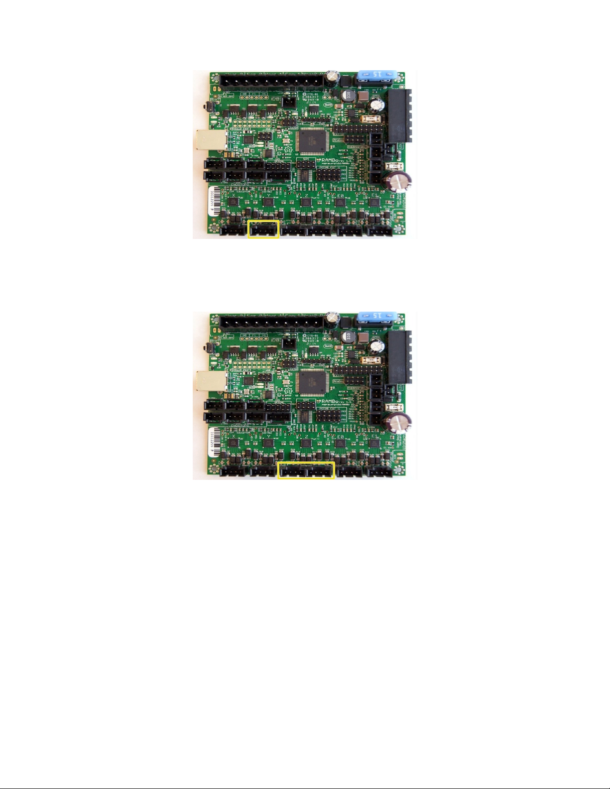
3. Attach the Z Axis Stepper to the RAMBo Z Driver plug, oriented the same manner as the above.
If your printer model uses two Z stepper motors insert the second Z stepper into the next marked port.
4. Attach the (Default) Right Extruder Stepper to the RAMBo E0 Driver plug, the blue goes toward the
USB Port. If you are installing a second Extruder Stepper to E1 Driver plug, install the second
extruder plug reversed. This makes the motor run in reverse, which is needed since the second
extruder is a mirror image of the first.
Page 89 of 151
Page 92
Maker's Tool Works MTW Create Assembly Guide - 1
Page 90 of 151
Page 93
Maker's Tool Works MTW Create Assembly Guide - 1
RAMBo – Connecting Endstops, ABL and Thermistors
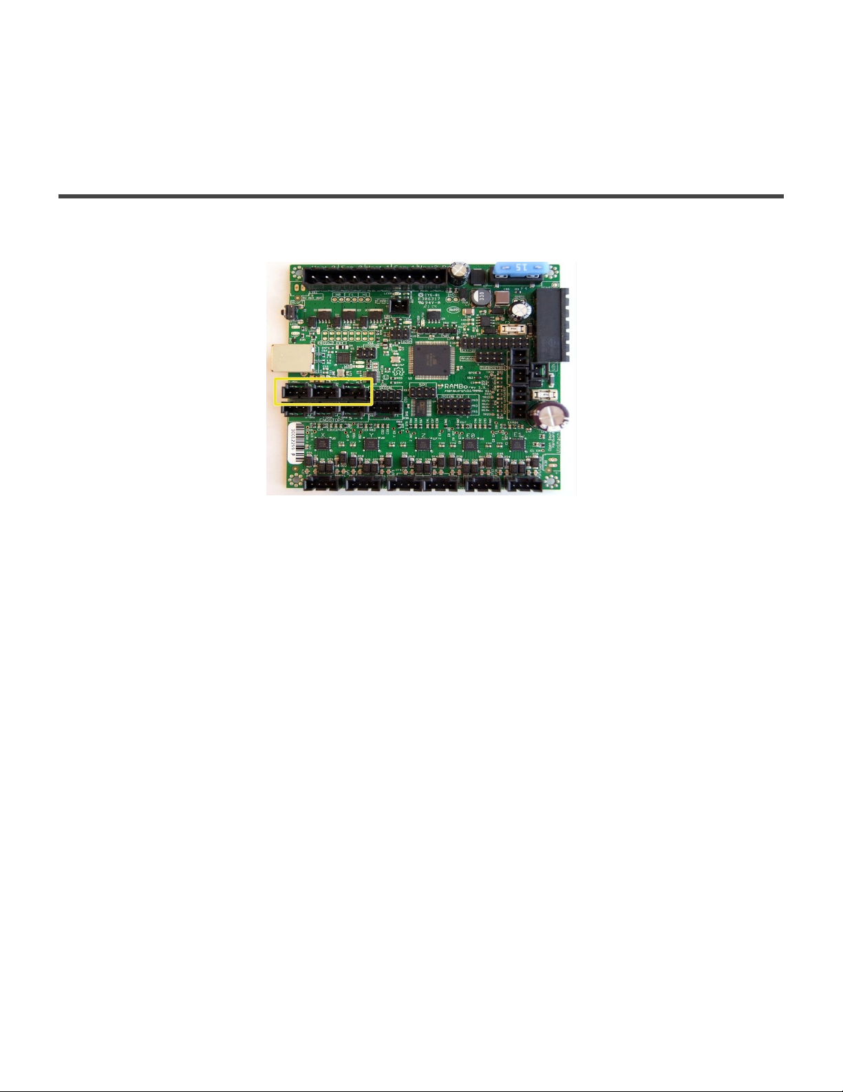
1. Pay attention to the labels on the board, and connect X and Y endstops to the correct min port.
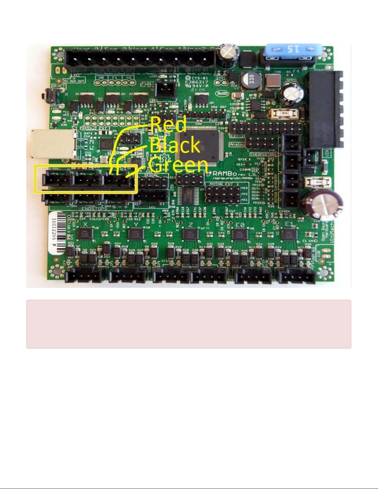
2. Install the ABL Sensor’s 3 pin plug into the RAMBo as shown.
• The red wire of the 3 pin connector goes to the + on the min Z endstop connector port.
• The black “center” wire of the 3 pin plug goes to the – of the min Z endstop port.
• The green wire of the 3 pin plug goes to the S position of the Z min endstop port.
Page 91 of 151
Page 94
Maker's Tool Works MTW Create Assembly Guide - 1
Verify 3 times that your 3 pin is inserted into the rambo as shown. Failure to follow
!
these directions will destroy the sensor and can also possibly damage your RAMBo
board. Warranty is not available for the sensor being improperly connected or any
subsequent damage done to the board.
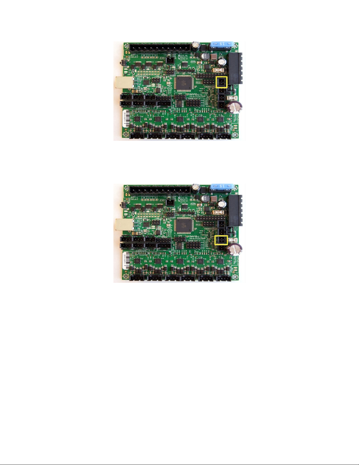
3. Install the Thermistor for the Default Right Hotend to the T0 plug. If you are installing a second
Hotend, its thermistor goes to the T1 plug, otherwise leave it unused. Thermistor plugs are not
polarized, and the orientation of the plug in the jack does not matter.
Page 92 of 151
Page 95
Maker's Tool Works MTW Create Assembly Guide - 1
4. Install the thermistor cable from the bed heater to the T2 jack. Again, the orientation of the plug does
not matter.
Page 93 of 151
Page 96
Maker's Tool Works MTW Create Assembly Guide - 1
RAMBo – Connecting Heaters
Included in the rambo controller are push in connectors with screws terminals for wire
termination.
*
You need to strip the ends of the cables before insertion into the connector.
If after stripping the cable the wires fray out you will need to twist the ends so they go
*
cleanly into the connector. Once the cable is twisted you place the wire into the open hole
and tighten the screw down. When done make sure there are no frayed wires that can short
to another wire sticking out.
On the cables for the bed heater pay special attention that the screws are very tight
!
compressing the wire and that the plug is fully secured into its plug. If this connection is
loose it will cause excess heat in the connection and will melt the plug plastic.
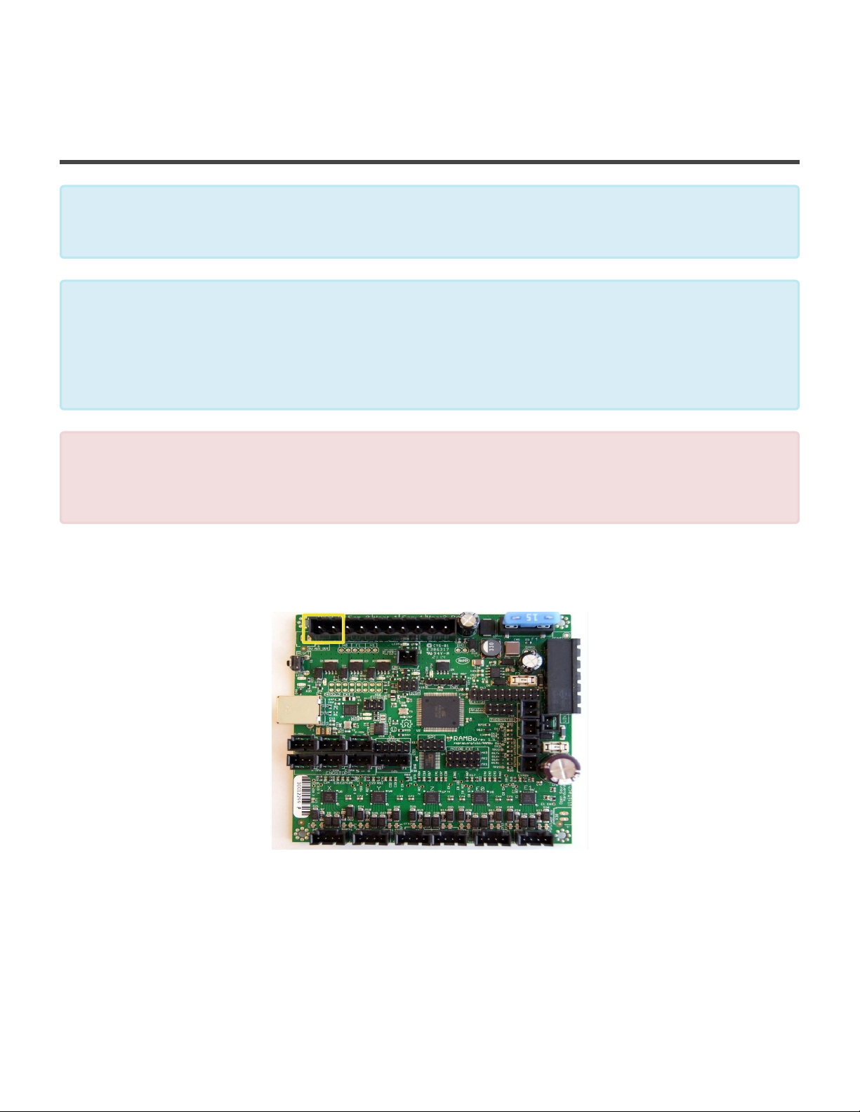
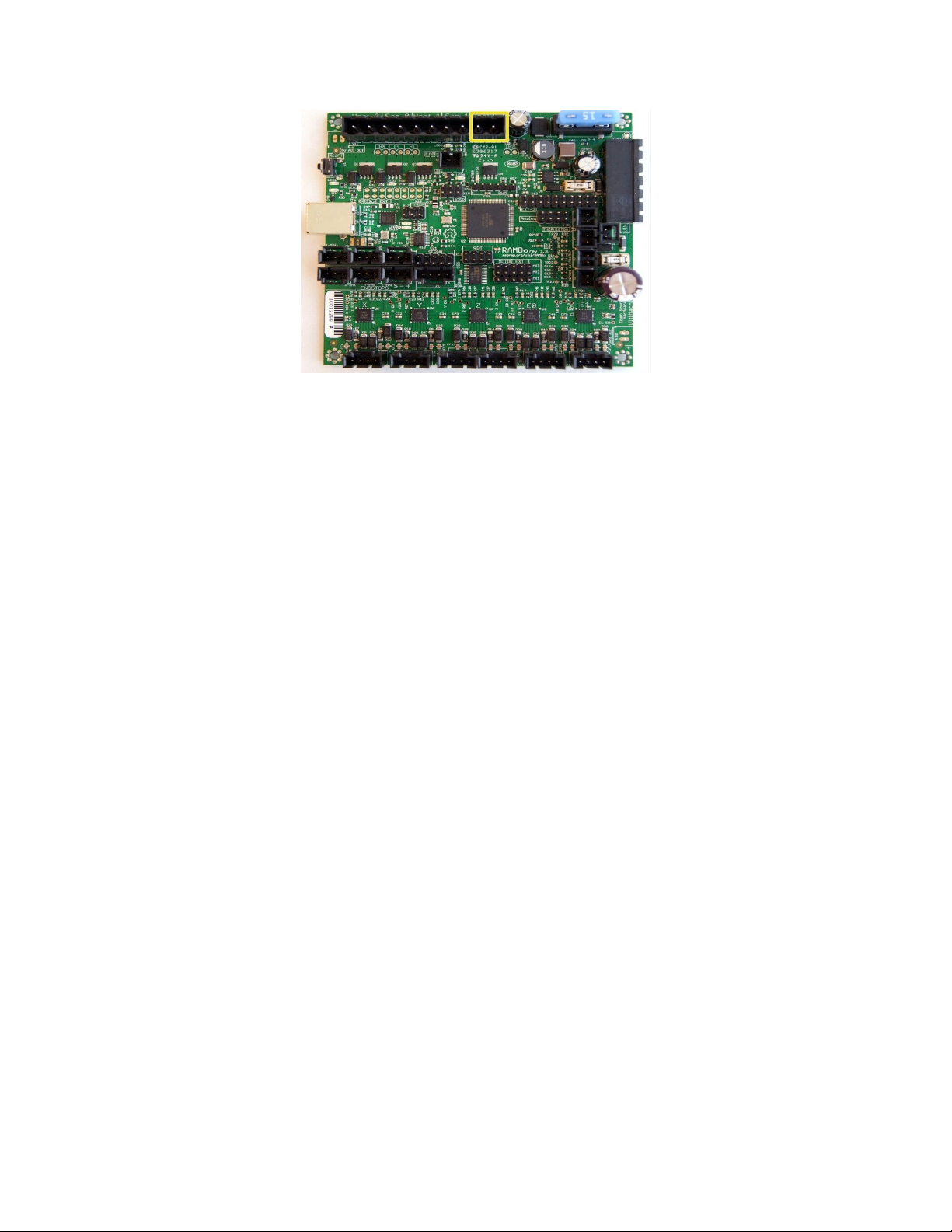
1. Install the wires for the Right Hotend heater into the two pin screw terminal connector and insert into
the plug labeled Heat0. If you are installing a second hotend, connect it to the plug labeled Heat1
2. Install the large wires from the heated bed into a two pin connector and install into the plug Heated
Bed.
Page 94 of 151
Page 97
Maker's Tool Works MTW Create Assembly Guide - 1
Page 95 of 151
Page 98
Maker's Tool Works MTW Create Assembly Guide - 1
RAMBo – Connecting Fans
If you have ordered a Dual Extruder kit, you will need to splice both sets of fans together.
Red to Red, Black to Black.
*
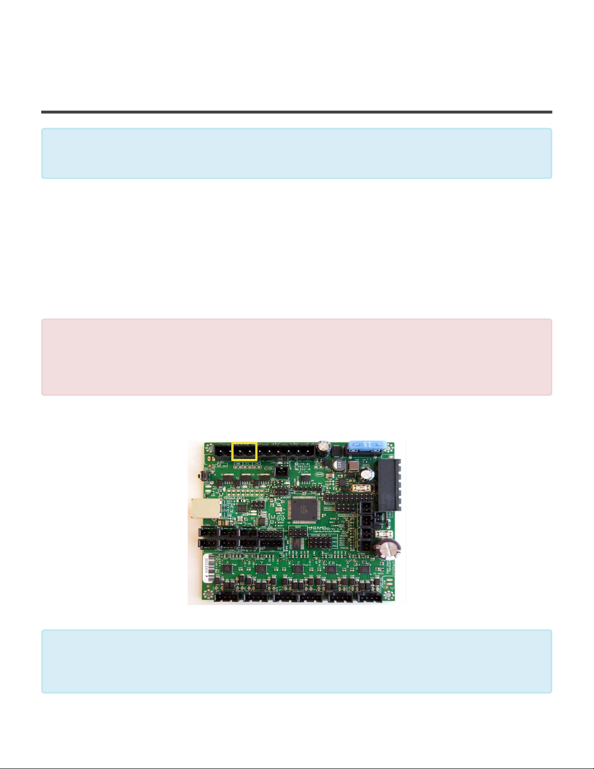
1. The kit may come with one or two fans to cool the print. ( a special fan is provided to cool the E3D
hotend barrel and is addressed later ) These fans may come with a white or black plug on the end.
Cut this connector off.
2. Strip the cables of the fan so that about 5mm of copper wire is exposed. Twist the two red wires from
each fan together. Twist the two black wires from each fan together. The red wires will go into the
screw connector that goes to the small + on the controller board. The black wires will go to the -.
If you get the fan connections wrong you will melt down your fans. ( replacements are in the
!
store! ) please double check that the red wires end up going to the + and the – goes to the
black wires. Do this after you install the plug since its easy to get it backwards in your hand.
Negative is toward the USB port, Positive is toward the big fuse.
3. The print fans install into the port labeled fan0
If your kit was supplied with a E3D hotend it comes with a 30mm fan to cool the E3d barrel.
This fan must be running at all times you are printing or it will cause you to have filament
*
jams. Do not run the E3D hotend without this fan installed and operating.
Page 96 of 151
Page 99
Maker's Tool Works MTW Create Assembly Guide - 1
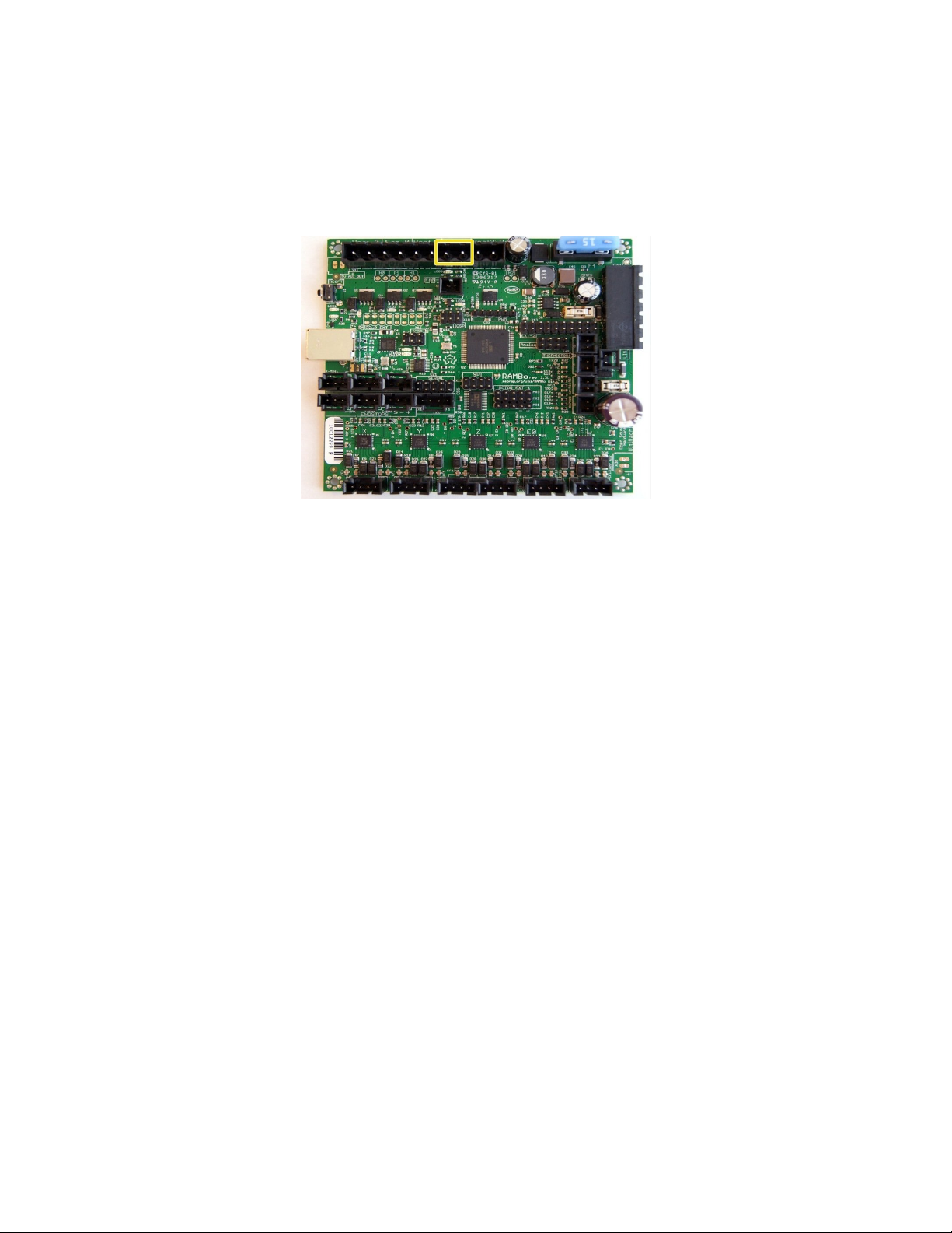
4. E3D fans connect to the plug labeled Fan1. Like the fans in the previous step install the cables into
the plug with the screws. Tighten down and make sure the + and – are in the right position as
indicated on the board in small print. The firmware is set to turn on the fans on Fan1 automatically
when the hotend reaches 60C.
Page 97 of 151
Page 100
Maker's Tool Works MTW Create Assembly Guide - 1
USB and testing
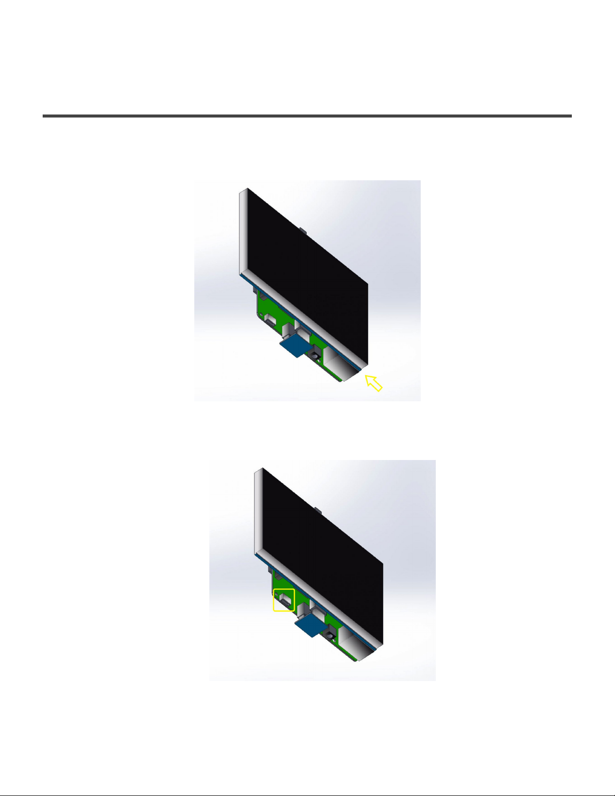
1. Your kit includes a short USB A/B cable. The cable plugs into the USB port on the RAMBo and the
closest USB Port on the RasPi
2. You may need to provide your own USB cable for powering the Pi, a standard phone charging cable
and a 2.5-3A phone charger will suffice. Connect it to the power port on the Pi.
Page 98 of 151
 Loading...