

Page 1
4R/6R 1000 EU Stage IV/US TIER 4
Operating Instructions
Page 2

Symbols
WARNING
G
Warning notes make you aware dangers
which could pose a threat to your health or
life, or to the health and life of others.
Environmental note
H
Environmental notes provide you with information on environmentally aware actions or
disposal.
The purpose of material damage warnings
!
is to draw your attention to risks which
could lead to damage to your engine system.
These symbols indicate useful instruc-
i
tions or further information that could be
helpful to you.
X
This symbol designates an instruction you must follow.
X
Several consecutive symbols indicate an instruction with several
steps.
(Y page)
This symbol tells you where you
can find further information on a
topic.
Y Y
This symbol indicates a warning or
an instruction that is continued on
the next page.
Display
This text indicates an indicator in
the display.
Page 3

Welcome
Familiarise yourself with your engine system
and read the Operating Instructions before
you use the engine system. This will help you
to avoid endangering yourself or others.
The standard equipment and product description of your engine system may vary, depending on individual specifications. This is described on the data card.
The engine systems are constantly updated
to be state of the art.
MTU/Mercedes-Benz reserves the right to
make changes to the following:
R
design
R
equipment
R
technical features
Descriptions may therefore differ in individual
cases from your engine system.
9345843771
É9345843771)ËÍ
Page 4

Page 5

Contents
3
Index ....................................................... 4
Introduction ........................................... 7
At a glance ........................................... 11
Safety ................................................... 23
Transport, installation ........................ 27
Operation ............................................. 29
Maintenance ........................................ 47
Decommissioning ............................... 57
Troubleshooting .................................. 59
Technical data ..................................... 71
Page 6

Index
4
A
AdBlue®/DEF
Consumption ................................... 42
Gauge .............................................. 35
Important safety notes .................... 44
Refuelling ......................................... 44
Service product ............................... 53
ADM (FR (drive control) unit) ............. 12
B
Battery (vehicle)
Jump starting ................................... 62
Braking
Continuous brake ............................ 33
Engine brake .................................... 33
Retarder ........................................... 33
Buzzer ................................................... 42
C
Capacities ............................................ 75
Care products ...................................... 55
Charge current .................................... 34
Checking the fluid level ...................... 30
Cleaning and care
Engine cleaning ................................ 55
High-pressure cleaning .................... 55
Notes on care .................................. 55
Consumption
AdBlue®/DEF .................................. 42
Fuel .................................................. 42
Oil (engine) ...................................... 42
Continuous brake
Important safety notes .................... 33
Coolant
Mixing ratio ...................................... 51
Service product ............................... 51
Topping up ....................................... 31
Coolant additive .................................. 51
Correct use ............................................ 8
Corrosion inhibitor/antifreeze
agent .................................................... 51
D
Data card .............................................. 72
DEF/AdBlue
see AdBlue®/DEF service products
Description of the engine ................... 12
Diagnostics connection ...................... 25
Diesel
Fuels ................................................ 52
Low outside temperatures ............... 52
Refuelling ......................................... 43
Dimensions .......................................... 73
Disposal of service products .............. 49
Driving mode
Idling speed ..................................... 33
Driving tips .......................................... 41
®
E
Electronic engine control
see Engine management
Electronic engine control unit ............ 34
Emergency gearshift
Using the emergency switch ............ 34
Emergency running program ................ 8
Engine
Capacities ........................................ 75
Cleaning ........................................... 55
Data ................................................. 72
Data card ......................................... 72
Data plate ........................................ 72
Modifying the power output ............... 8
Oil consumption ............................... 42
Operating data ................................. 74
Rectifying faults ............................... 65
Running-in period ............................. 41
Starting ............................................ 31
Stopping .......................................... 32
Engine brake ........................................ 33
Engine data .......................................... 72
Engine data card .................................. 72
Engine description .............................. 12
Engine idling speed ............................. 33
Engine management ........................... 18
Engine oil
Consumption ................................... 42
For winter operation ........................ 49
Page 7

Index
5
Mixing .............................................. 50
Oil change ........................................ 50
Topping up ....................................... 50
Engine overview .................................. 13
Engine speed ....................................... 35
Exhaust gas aftertreatment ............... 20
F
Fuel
Additives .......................................... 53
Consumption ................................... 42
Diesel ............................................... 52
Refuelling ......................................... 43
Fuel grade ............................................ 52
Fuel system
Automatic bleeding .......................... 61
Manual bleeding .............................. 61
Fuses
Checking and replacing a safety
fuse .................................................. 62
Important safety notes .................... 62
G
Gauge
AdBlue®/DEF .................................. 35
Genuine Mercedes-Benz parts ............. 7
H
High-pressure cleaning ....................... 55
I
Identification plate .............................. 72
Idling speed
Engine .............................................. 33
Installation ........................................... 28
J
Jump-starting ....................................... 62
M
Maintenance
Notes ............................................... 48
Mercedes-Benz Service Centre
see Qualified specialist workshop
O
Oil (engine)
For winter operation ........................ 49
Oil change ........................................ 50
Scope of use .................................... 50
Oil pressure ......................................... 34
Operating data ..................................... 74
Operating instructions
General notes .................................. 10
Operating safety .................................. 24
Operating safety and registration
Changes in engine performance ........ 8
Implied warranty ................................ 8
Operational monitoring ...................... 34
Organisational measures ................... 25
P
Personnel ............................................. 25
Preparing for starting operation
see Starting operation
Protection of the environment ............. 7
Q
Qualified specialist workshop ........... 10
R
Refuelling
AdBlue®/DEF .................................. 44
Fuels ................................................ 43
Requirements of the personnel ......... 25
Rev counter .......................................... 35
Roadside Assistance ........................... 60
Running the vehicle in ........................ 41
S
Safety and emergency running pro-
gram ....................................................... 8
Safety precautions .............................. 24
Service products
AdBlue®/DEF .................................. 53
Coolant ............................................ 51
DEF/AdBlue® .................................. 53
Diesel fuel ........................................ 52
Disposal ........................................... 49
Page 8

Index
6
Disposing of AdBlue®/DEF .............. 54
Engine oil ......................................... 49
Fuel additives ................................... 53
General notes .................................. 49
Purity of AdBlue®/DEF .................... 55
Storing AdBlue®/DEF ...................... 54
Specialist workshop ............................ 10
Starting
see Starting (engine)
Starting (engine) .................................. 31
Stopping and switching off the
engine ................................................... 31
T
Technical data
Dimensions ...................................... 72
Filling capacities .............................. 75
Operating data ................................. 74
Weights ............................................ 72
Tightening torques .............................. 76
Transport .............................................. 28
W
Warning and indicator lamps
Electronics ....................................... 36
Engine, general ................................ 20
Warning buzzer .................................... 42
Weights ................................................ 73
Winter diesel ........................................ 52
Winter operation ................................. 45
Page 9

Introduction
7
Engine system
The 4R 1000 and 6R 1000 series of engines
only function as intended when used in conjunction with the corresponding exhaust gas
aftertreatment unit. Therefore, in these Operating Instructions, the term "engine system"
refers to the engine and the exhaust gas aftertreatment unit.
Protection of the environment
Environmental note
H
Daimler AG has a declared policy of comprehensive environmental protection.
The objectives are to use the natural resources which form the basis of our existence on
this planet sparingly and in a manner which
takes the requirements of both nature and
humanity into account.
You too can help to protect the environment
by operating your vehicle in an environmentally responsible manner.
Information and notes on driving in an environmentally responsible and fuel-saving manner can be found in the "Operating notes"
section (Y page 42).
Assembly equipment
These Operating Instructions describe all
models and all standard and optional equipment available for your engine system at the
time of publication of the Operating Instructions. Country-specific deviations are possible. Note that your engine system may not be
fitted with all features described. This also
applies to safety-relevant systems and functions. Therefore, the equipment on your
engine system may differ from certain
descriptions and illustrations.
All of the components in your engine system
are listed in the data card of your engine system. Data card (Y page 72).
Please contact an MTU or MTU-authorised
Mercedes-Benz Service Centre if you have
any questions about the equipment or operation.
Genuine Mercedes-Benz parts
Environmental note
H
Daimler AG also supplies reconditioned
assemblies and parts which are of the same
quality as new parts. For these, the same warranty applies as for new parts.
If you use parts which have not been
approved by Mercedes-Benz, the operational
safety of the engine system may be jeopardised. This could lead to malfunctions in
safety-relevant systems. Use only genuine
Mercedes-Benz parts or parts of equal quality. Only use parts that have been approved
for your engine type.
Mercedes-Benz checks genuine MercedesBenz parts for:
R
reliability
R
safety
R
suitability
Despite ongoing market research, MercedesBenz is unable to assess other parts.
Mercedes-Benz therefore accepts no responsibility for the use of such parts in MercedesBenz vehicles, even if they have been officially
approved or independently approved by a
testing centre.
In Germany, certain parts are only officially
approved for installation or modification if
they comply with legal requirements. This
also applies to some other countries. All genuine Mercedes-Benz parts meet the approval
requirements. The use of non-approved parts
may invalidate the vehicle's general operating
permit.
Z
Page 10

Introduction
8
This is the case if:
R
they result in a change to the vehicle type
from that for which the vehicle's general
operating permit was granted
R
they pose a possible risk for road users
R
they adversely affect the emission or noise
levels
You can find more information on recommended conversion parts and accessories, as well
as permitted technical modifications at a
Mercedes-Benz or MTU Service Centre
(Y page 10).
Always specify the engine number and the
number of the exhaust gas aftertreatment
unit when ordering genuine Mercedes-Benz
parts. You can find the engine number on the
identification plate of your engine. You can
find the number of the exhaust gas aftertreatment unit on the identification plate of the
exhaust gas aftertreatment control module
(ACM) (Y page 72). You can also find the
two numbers on the data card (Y page 72).
Modifying the engine output
Increased power could:
!
R
change emission levels
R
cause malfunctions
R
lead to consequential damage
The operating safety of the engine cannot
be guaranteed in all situations.
Any tampering with the engine management
system in order to increase the engine power
output will lead to a loss of warranty entitlements.
If the electronic control system detects a malfunction, one of the following measures is
automatically implemented after an appraisal
of the malfunction:
R
faults during operation are indicated by the
corresponding warning lamp (Y page 34).
R
in conjunction with the electronic engine
management system, fault codes with additional information can be shown on a display.
R
the system switches to a suitable backup
function for the continued, albeit restricted, operation of the engine. This includes
torque and engine speed limitation, for
example, as well as road speed limitation or
constant emergency running speed.
Correct use
The engine system may only be installed as
contractually specified.
The manufacturer of the end product is
responsible for the correct installation of the
engine and the exhaust gas aftertreatment
system in the overall system.
The engine and the exhaust gas aftertreatment system may not be modified. If the
engine is modified, Mercedes-Benz and MTU
do not accept responsibility for any damage
arising as a result.
Correct use of the engine system also
requires adherence to the instructions in
these Operating Instructions. This also
requires compliance with the maintenance
intervals and the professional execution of
maintenance work. Please observe the Workshop Information System (WIS) (Y page 10).
Safety/emergency running program
The engine is equipped with an electronic
engine management system that monitors
the engine and the exhaust gas aftertreatment unit and has a self-diagnostic system.
Implied warranty
A well-developed network of Mercedes-Benz
Service Centres is available to carry out maintenance work.
Page 11

Introduction
9
Mercedes-Benz Service Centres:
R
have special equipment and tools as well as
specialists who receive continuous training
R
guarantee that your engine system is
repaired and maintained thoroughly and
expertly
R
carry out all repairs related to implied warranty
R
carry out all maintenance work expertly
R
confirm in the Maintenance Booklet that
the maintenance work has been carried out
at the required time
R
handle implied warranty claims that are
admissible according to the sales contract
Please observe the instructions and recommendations as well as the maintenance services in the Maintenance Booklet. Please
observe these instructions even if you let a
third party use and care for your vehicle/
device. This is the only way to ensure that you
do not lose your entitlements.
If the prescribed maintenance work is not
carried out, claims can only be decided after
the manufacturer has inspected the claim.
During the implied warranty period, have the
prescribed maintenance service for your
engine system carried out as follows:
R
regularly
R
punctually
R
at a qualified specialist workshop which
has the necessary specialist knowledge
and tools to carry out the work required
Mercedes-Benz recommends that you use
a Mercedes-Benz Service Centre for this
purpose. In particular, work relevant to
safety or on safety-related systems must
be carried out at a qualified specialist workshop.
If there are legal requirements on emission
control, please note that:
R
maintenance on the engines must be carried out according to specific regulations
and using special measuring devices
R
it is prohibited to modify or tamper with
components relevant to emissions
All Mercedes-Benz Service Centres are familiar with the relevant regulations.
Maintenance work does not include repair
work. Issue a separate order for repair work.
You can obtain further information on the
maintenance of your engine system from any
Mercedes-Benz Service Centre.
Stored data
Several of the electronic components in your
engine system contain data memories.
These data memories temporarily or permanently store technical information about:
R
the engine system state
R
events
R
malfunctions
In general, this technical information documents the state of a component, a module, a
system or the surroundings.
This includes, for example:
R
operating conditions of system components, e.g. fluid levels
R
status messages for the vehicle/equipment and its individual components, e.g.
speed, deceleration in movement, accelerator position
R
malfunctions and defects in important system components
R
the reactions and operating statuses of the
vehicle/equipment in special driving situations
R
ambient conditions, e.g. outside temperature
Z
Page 12

Introduction
10
This data is exclusively technical in nature
and can be used to:
R
assist in the detection and rectification of
faults and defects
R
analyse vehicle functions, e.g. after an accident
The data cannot be used to trace the vehicle's
movements.
When you use one of the available services,
technical information may be read from the
event data memory and fault data memory.
Services include, for example:
R
repair services
R
service processes
R
implied warranty and guarantee cases
R
quality assurance
The information is read out by employees of
the service network (including manufacturers) using special diagnostic testers. Further
information is available there if required.
After a fault has been rectified, the information is deleted from the fault memory or is
continually overwritten.
Further applicable documents
To use the engine correctly, you require the
Maintenance Booklet in addition to these
Operating Instructions.
For US-certified engines you also require the
"Emission Related Warranty" supplement.
Always keep these documents together with
the engine/vehicle/equipment. These documents should be passed on to the new owner
if you sell the engine/vehicle/device.
When carrying out maintenance work, you
require access to the Workshop Information
System (WIS) via the Internet. This access is
subject to a fee.
Current information on the system and prices
can be found at this web address: http://
service-parts.mercedes-benz.com. Click on
"EPC, WIS/ASRA" in the "Service and parts
information" tab and then on "WIS".
You can log in by clicking on "Register" on the
right-hand side.
Qualified specialist workshop
A qualified specialist workshop has the necessary specialist knowledge, tools and qualifications to carry out the work required on the
engine to a professional standard. This is particularly applicable to work relevant to safety.
Observe the notes in the Maintenance Booklet.
Always have the following maintenance work
carried out at a qualified specialist workshop:
R
work relevant to safety
R
service and maintenance work
R
repair work
R
modifications as well as installations and
conversions
R
work on electronic components
Please consult an MTU or MTU-authorised
Mercedes-Benz partner.
Page 13

General information ............................ 12
Engine overview .................................. 13
Exhaust gas aftertreatment over-
view ...................................................... 17
Electronic engine management ......... 18
Exhaust gas aftertreatment ............... 20
Exhaust gas recirculation .................. 20
Warning and indicator lamps ............. 20
11
At a glance
Page 14

General information
12
General information
The engine is a water-cooled four-stroke diesel engine with direct injection.
The engine is equipped with a Common Rail
diesel injection system, cooled and regulated
exhaust gas recirculation and turbocharging
with charge-air pressure control.
At a glance
Depending on the engine output, engine turbocharging is either by means of single-stage
exhaust turbocharging or two-stage exhaust
gas turbocharging with two sequential
exhaust gas turbochargers of differing dimensions.
The valve gear has twin overhead camshafts
which are gearwheel-driven.
The engine has a single-part cylinder head. In
the cylinder head there are two inlet valves
and two exhaust valves per cylinder. The
valves are arranged symmetrically. The symmetrical valve arrangement is optimal for
combustion .
The exhaust gas aftertreatment unit is characterised by the following technologies:
R
selective catalytic reduction (SCR) with
ammonia slip catalytic converter
R
the diesel oxidation catalytic converter
(DOC)
The engine brake is a decompression brake. It
has a controlled exhaust valve which gives it
high braking power. The engine brake can be
controlled stepwise or modulated.
Page 15
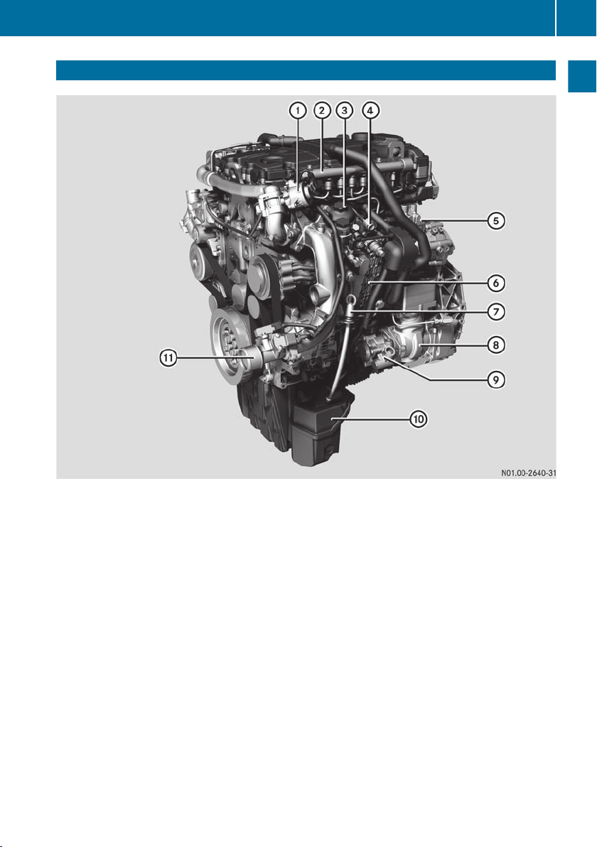
Engine overview
Engine overview
13
At a glance
Engine overview: 4R 1000 with single-stage charging
:
Exhaust gas recirculation positioner
;
Rail
=
Fuel filter
?
External engine start/engine stop button
A
High-pressure fuel pump
B
Engine management control module (MCM)
C
Dipstick
D
Air compressor
E
Power-steering pump
F
Oil pan
G
Charge-air pipe (cold)
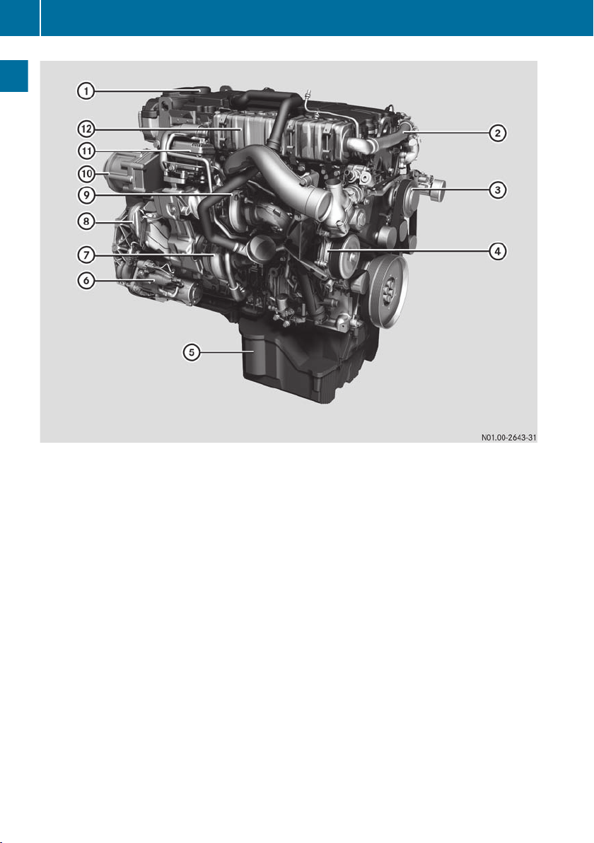
Page 16
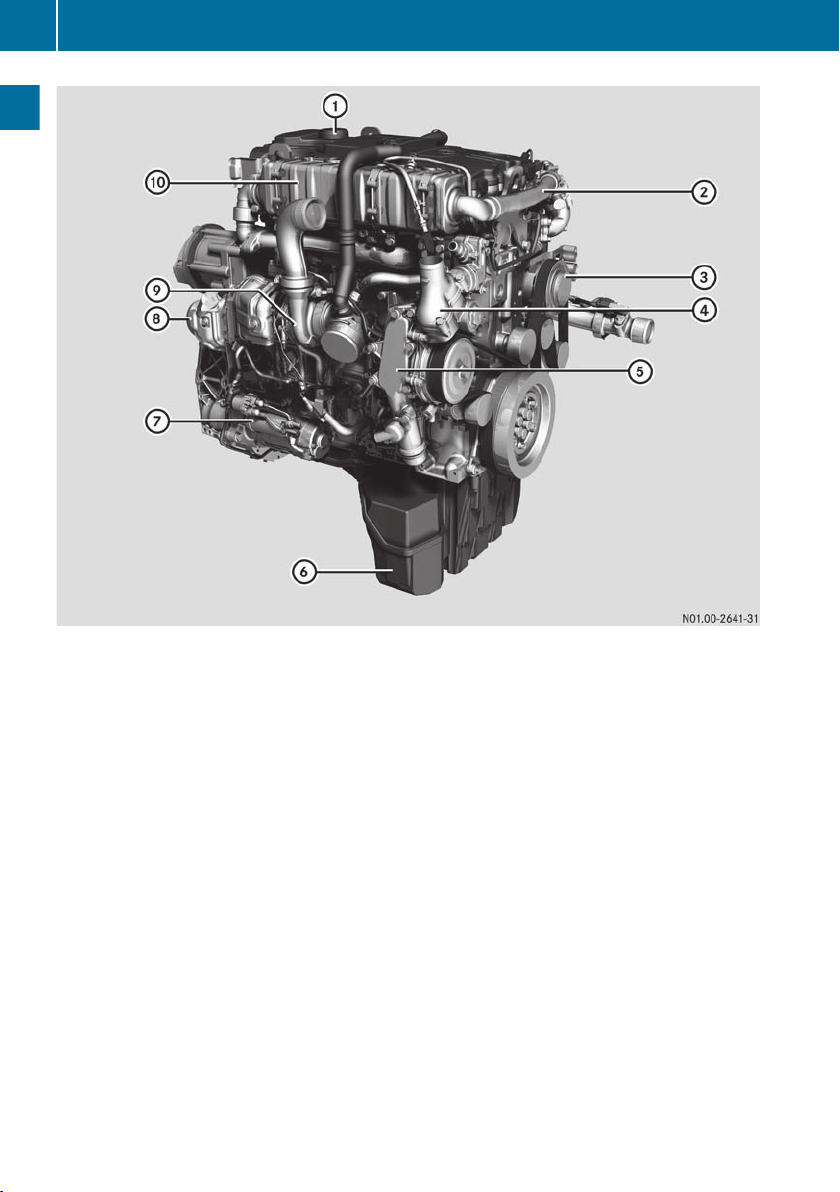
Engine overview
14
At a glance
Engine overview: 4R 1000 with single-stage charging
:
Crankcase ventilation system
;
Exhaust gas recirculation pipe (cold)
=
Refrigerant compressor
?
Coolant thermostat
A
Combined oil filter/oil cooler module with coolant pump
B
Oil pan
C
Starter motor
D
Exhaust pipe to exhaust gas aftertreatment unit
E
Exhaust gas turbocharger
F
Exhaust gas recirculation cooler
Page 17
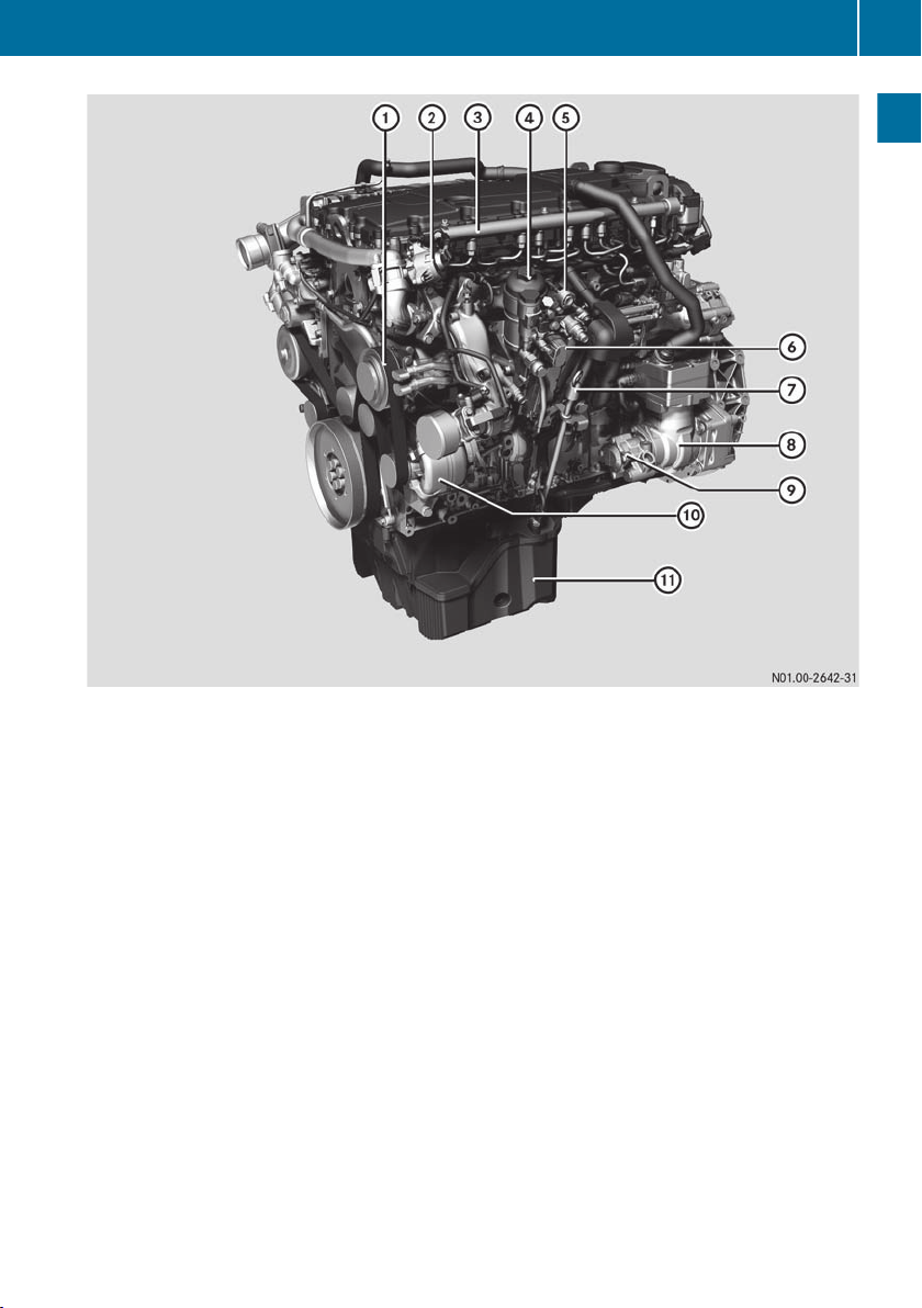
Engine overview
15
At a glance
Engine overview: 6R 1000 with two-stage charging
:
Refrigerant compressor
;
Exhaust gas recirculation positioner
=
Rail
?
Fuel filter
A
External engine start/engine stop button
B
Engine management control module (MCM)
C
Dipstick
D
Air compressor
E
Power-steering pump
F
Alternator
G
Oil pan
Page 18
Engine overview
16
At a glance
Engine overview: 6R 1000 with two-stage charging
:
Crankcase ventilation system
;
Exhaust gas recirculation pipe (cold)
=
Refrigerant compressor
?
Combined oil filter/oil cooler module with coolant pump
A
Oil pan
B
Starter motor
C
Low pressure exhaust gas turbocharger
D
Exhaust pipe to exhaust gas aftertreatment unit
E
High pressure exhaust gas turbocharger
F
Power take-off (PTO)
G
Boost pressure positioner
H
Exhaust gas recirculation cooler
Page 19
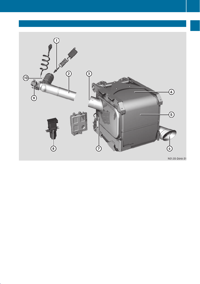
Exhaust gas aftertreatment overview
Exhaust gas aftertreatment overview
17
At a glance
:
NOx sensor on exhaust gas aftertreatment unit inlet
;
AdBlue® treatment reactor
=
Exhaust gas inlet from AdBlue® treatment reactor
?
Position of identification plate
A
Exhaust gas aftertreatment box
B
Exhaust gas outlet
C
Exhaust gas temperature sensor upstream of the SCR catalytic converter
D
Pump module
E
AdBlue®/DEF metering unit
F
Exhaust gas temperature sensor upstream of the AdBlue® metering unit
Page 20
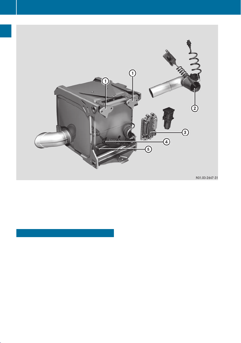
Electronic engine management
18
At a glance
:
Mounting brackets
;
Exhaust gas inlet from engine
=
Exhaust gas aftertreatment control unit (ACM)
?
NOx sensor at exhaust gas aftertreatment unit outlet
A
Exhaust gas temperature sensor downstream of the SCR catalytic converter
Electronic engine management
In addition to the engine, the exhaust gas
aftertreatment and the vehicle/equipment-
The engine system is equipped with an electronic engine management system which
comprises the following control units:
R
Engine management control module
(MCM)
R
Drive control system unit (CPC)
R
Exhaust gas aftertreatment control unit
(ACM)
The control units are connected in an electronic network. Data is exchanged via CAN
(Controller Area Network).
side connection, the electronic engine management system also monitors itself.
Depending on the malfunctions/failures
which occur, warning and information displays are activated (Y page 20). The malfunction is stored in the fault memory and if
necessary a safety and emergency mode is
automatically selected (Y page 34). If the
electronic engine management control
detects a fault, the fault code is stored in the
control units. It can then be read by a qualified
specialist workshop (Y page 10) using a diagnostic tester.
Page 21

Electronic engine management
19
Engine management control module (MCM)
The engine management control module
(MCM) is located on the side of the engine. It
acts as an interface between the electric and
electronic components on the engine/equipment and the drive control system unit (CPC)
on the vehicle.
The engine management control module
(MCM) has many functions:
R
Injection control of the Common Rail diesel
injection system
The engine management control module
(MCM) calculates the optimum start and
quantity of injection, taking the torque
demand from the drive control system unit
(CPC) into account.
All of the data required for this, e.g. power
output or data which serve to protect the
engine, are stored in the engine management control module (MCM).
R
Regulation of exhaust gas recirculation
(EGR)
The ratio between the mass of recirculated
exhaust gas and the fresh air mass is precisely regulated over the entire engine
speed range.
R
Charge-air pressure control
R
Control of the engine brake
The engine management control module
(MCM) controls the engine brake as
required by the drive control system unit
(CPC).
R
Fan regulation
In optional fan regulation, the solenoid
valve on the fan clutch is activated according to coolant temperature.
R
Instrument cluster display
The engine management control module
(MCM) detects the oil level, engine oil temperature, oil pressure, coolant temperature
and the engine speed for the displays in the
instrument cluster.
Drive control system unit (CPC)
The drive control system unit (CPC) is installed in a protected location in the vehicle/
equipment by the vehicle/equipment manufacturer. It acts as an interface between the
electric and electronic components on the
vehicle/equipment and the engine management control module (MCM) on the engine.
The drive control system unit (CPC) has many
functions:
R
Calculation of torque demand
The drive control system unit (CPC) registers the driver's requirements. For example, the position of the accelerator is detected by the drive control system unit (CPC).
A torque requirement is calculated from
that and sent to the engine management
control module (MCM) via the CAN connection.
In doing so, information and limitations
from optionally connected control units
such as the gearbox control, retarder control, ABS and ASR are taken into account.
R
Output of displays and indicator signals
which are displayed in the instrument cluster.
R
Monitoring of coolant level, charge current
and air filter, for example
R
Legal speed limitation
R
Evaluation of start request
The engine starting process is initiated
once a corresponding start request is present (ignition lock or external engine start/
engine stop button).
Exhaust gas aftertreatment control unit (ACM)
The exhaust gas aftertreatment control unit
(ACM) is installed in a protected location in
the vehicle/equipment by the vehicle/equipment manufacturer. It regulates and controls
the exhaust gas aftertreatment system.
At a glance
Page 22

Warning and indicator lamps
20
Functions of the exhaust gas aftertreatment
control unit (ACM):
R
Evaluation of sensor signals
The sensor signals of the directly connected sensors are evaluated. Data provided
via the CAN by the engine management
control module (MCM) and the control
units for the NOx sensors are also evalu-
At a glance
ated.
R
AdBlue®/DEF injection
Calculation of the required amount of
AdBlue®/DEF and supply of AdBlue®/DEF
by actuation of the SCR delivery pump.
Injection by actuation of the AdBlue®/DEF
metering unit.
Exhaust gas aftertreatment
The exhaust gas aftertreatment system is
activated immediately after the engine is started and remains activated during engine
operation. It ensures that the pollutant emissions in the exhaust gas are reduced to the
limits stipulated in the emissions standard.
Exhaust gas treatment is carried out by:
R
selective catalytic reduction (SCR) with
ammonia slip catalytic converter
R
the diesel oxidation catalytic converter
(DOC)
In order to ensure correct operation of the
exhaust gas aftertreatment system, only
operate the engine/vehicle with the AdBlue
reducing agent. AdBlue® is not refilled as part
of the maintenance work. You should therefore top up the AdBlue® tank regularly yourself.
Operating the vehicle/equipment without
AdBlue® or with another, non-Mercedes-Benz
or non-MTU approved medium, invalidates
the engine's operation certification/
approval.
Exhaust gas recirculation
Exhaust gas recirculation (EGR) serves primarily to reduce the amount of nitrogen oxide
prior to exhaust gas aftertreatment. This
serves to comply with emissions limits.
Exhaust gas is added to the fresh air being
drawn in or charged so that the concentration
of oxygen in the combustion mixture is
reduced. Combustion deteriorates if the concentration of exhaust gas in the combustion
mixture is too high. The emission of soot particles, carbon monoxide (CO) and hydrocarbons (HC) increases. Conversely, the emission of nitrogen oxides (NOx) would increase,
if the concentration of fresh or charged air
was too high.
Warning and indicator lamps
Important safety notes
If you ignore warning and indicator lamps, you
will not be able to recognise failures and malfunctions in components or systems. Driving/braking characteristics may be different
and the operating and road safety of your
vehicle/equipment may be limited. Have the
affected system checked and repaired at a
qualified specialist workshop. Always
observe the warning and indicator lamps and
follow the corresponding corrective actions
(Y page 36).
®
Overview
The display format for warning and indicator
lamps is vehicle-specific/equipment-specific. Observe the information contained in
the Operating Instructions for the vehicle/
equipment. The symbols listed below are
examples and may differ from those symbols
displayed in the vehicle/equipment.
In the event of a fault or warning, a warning
lamp or indicator lamp lights up automatically. Depending on the priority of the fault or
Page 23
warning, the warning and indicator lamps
light up in different combinations.
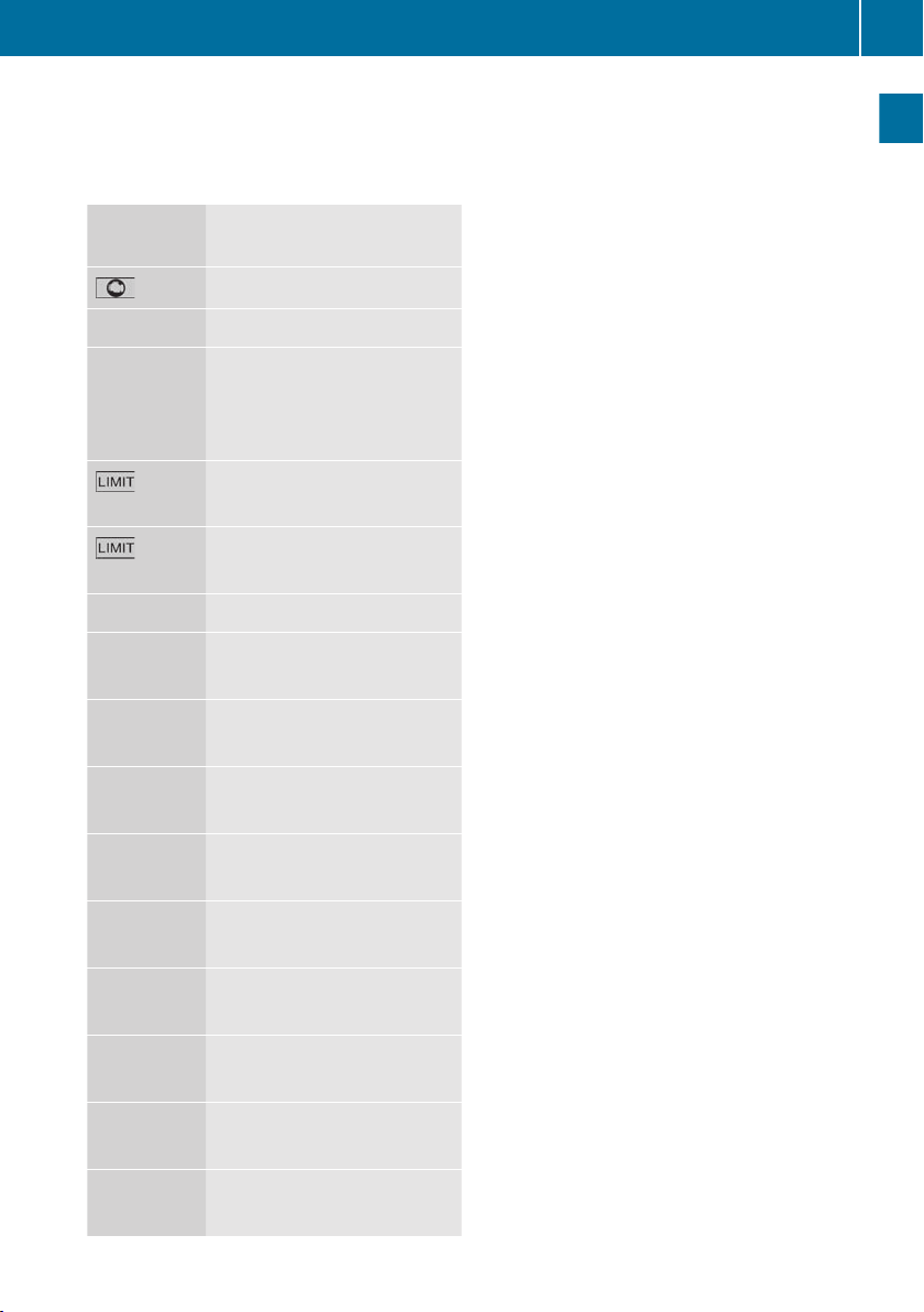
The following warning and indicator lamps
may be available on the instrument panel:
Warning and indicator lamps
21
Indicator
lamp
red
Ù
·
(lit con-
stantly)
(flash-
ing)
#
Ø
(optional)
5
(optional)
4
(optional)
,
(optional)
Description
Engine stop
Engine system malfunction
Emissions-relevant malfunction of the exhaust gas aftertreatment system or
AdBlue®/DEF supply
Torque operating restriction
Torque and engine speed
operating restriction
Charge current
AdBlue®/DEF reserve level
Oil pressure too low (engine)
Oil level too low (engine)
Coolant level too low
At a glance
?
(optional)
Ã
(optional)
é
(optional)
È
(optional)
I
(optional)
Coolant temperature too
high
Continuous brake active
Cruise control
Speed limiter
Power take-off engaged
Page 24

22
Page 25

Operating safety ................................. 24
Safety precautions .............................. 24
Notes on electronic systems ............. 24
Staff qualifications ............................. 25
Organisational measures ................... 25
23
Safety
Page 26

Notes on electronic systems
24
Operating safety
WARNING
G
If you do not have the prescribed service/
maintenance work or necessary repairs carried out, this could result in malfunctions or
system failures. There is a risk of an accident.
Safety
Always have the prescribed service/maintenance work as well as necessary repairs carried out at a qualified specialist workshop.
The operating safety of an engine system
depends on its professional installation in the
overall system (e.g. the vehicle or working
machinery). As the operator of the engine,
you also affect its safe operation.
Through compliance with the prescribed
maintenance intervals, you fulfil part of the
requirements for safe operation of the
engine.
However, safe operation of the engine also
depends upon its proper use and care. This
includes, for example, regularly checking the
oil level.
R
Please note, when carrying out electric
welding work, that the batteries must be
disconnected and both of the cables ("+"
and "-") must be firmly attached to each
other.
R
The control unit connectors may only be
connected/disconnected when the electrical system is switched off.
R
Incorrect control unit-power supply
polarity (e.g. by connecting up the batteries incorrectly) can cause irreparable
damage to the control units.
R
Tighten diesel injection system connections to the prescribed tightening torque.
R
If temperatures above 80 † are to be
expected (e.g. in a drying oven), the control unit on the engine must be removed.
R
Only use the appropriate testing probes
when taking measurements from electrical connectors (e.g. a Mercedes-Benz
connection set). Telephones and twoway radio devices that are not connected
to an external aerial can cause malfunctions in the electronics and thus endanger the operating safety of the engine.
Safety precautions
Damage to the engine can also lead to personal injury. In order to avoid engine damage,
the following safety precautions must be
adhered to.
R
Only start the engine when the batteries
are firmly attached.
R
Do not disconnect the batteries when the
engine is running.
R
Do not use a rapid charger to start the
engine.
R
Only perform the jump-starting procedure with separate batteries.
R
Note, the battery terminals must be disconnected when rapid charging the batteries.
R
Observe the operating instructions of the
rapid battery charger.
Warning stickers
If you remove any warning stickers, you or
others could fail to recognise certain dangers.
Various warning stickers are attached to the
engine system. Their purpose is to make you
and others aware of various risks.
Notes on electronic systems
Important safety notes
WARNING
G
Modifications to electronic components, their
software as well as wiring could effect their
function and/or the operation of other networked components. This could in particular
also be the case for systems relevant to
safety. They might not function properly any
Page 27

Organisational measures
25
more and/or jeopardise the operational
safety of the vehicle. There is an increased
risk of an accident and injury.
Do not attempt to modify the wiring as well as
electronic components or their software.
Always have work on electrical and electronic
components carried out at a qualified specialist workshop.
The general operating permit for your vehicle/equipment could be rendered invalid if
you carry out modifications to electronic
components, their software or their wiring.
Electromagnetic compatibility
The electromagnetic compatibility of the
engine system's components has been
checked and certified according to the currently valid version of Directive ECE-R 10.
Diagnostics connection
The diagnostics connection is used for connecting diagnostic equipment at a qualified
specialist workshop.
WARNING
G
If you connect equipment to a diagnostics
connection in the vehicle, it can affect the
operation of the vehicle systems. This may
affect the operating safety of the vehicle.
There is a risk of an accident.
Do not connect any equipment to a diagnostics connection in the vehicle.
If the engine is switched off and devices connected to the diagnostics connection are
being used, the starter battery can become
discharged.
Connecting devices to the diagnostics connection can, for example, cause the emissions monitoring information to be reset. As a
result, there is a possibility that the vehicle/
equipment will not fulfil the requirements of
the next legally prescribed emissions test.
Staff qualifications
WARNING
G
If you do not have the prescribed service/
maintenance work or necessary repairs carried out, this could result in malfunctions or
system failures. There is a risk of an accident.
Always have the prescribed service/maintenance work as well as necessary repairs carried out at a qualified specialist workshop.
The engine should only be operated, maintained and repaired by trained personnel who
have been briefed and authorised by the operator. The prescribed minimum legal age for
personnel carrying out maintenance and
repair work must be observed.
Organisational measures
The operator must determine the responsibilities for operation, maintenance and
repairs. Give the Operating Instructions and
the Maintenance Booklet to the personnel
that are charged with operating or carrying
out work on the engine.
Instruct personnel on how to operate the
engine using the Operating Instructions.
When doing so, put special emphasis on
safety-relevant information. This is particularly important for personnel that only work
occasionally on the engine.
Always keep the Operating Instructions and
the Maintenance Booklet readily accessible,
in the area of engine operation.
In addition to the Operating Instructions,
other general, country-specific, legal and
other binding regulations on accident prevention and environmental protection must be
adhered to.
Safety
Z
Page 28

26
Page 29

Transport ............................................. 28
Installation ........................................... 28
27
Transport, installation
Page 30
Installation
28
Transport
WARNING
G
If you do not lift the engine as described, the
lugs intended for the purpose may be torn out
or snap. This may be the case especially if the
maximum permissible lug load is exceeded.
The engine could then drop uncontrolled,
causing serious or even fatal injury.
Always make sure that:
R
the engine is only lifted at the intended lifting points/lifting lugs.
R
the engine is only lifted and transported in
the fitting position.
R
ropes/chains are always routed vertically.
R
only parts which are typically in the original
scope of delivery are attached to the
Transport, installation
engine.
The engines are by default delivered filled
!
with oil. If the engine is transported at an
angle or on its side, oil could leak out. Only
transport the engine in the installation position.
Do not stand on the engine or the exhaust
!
gas aftertreatment unit. They may otherwise be damaged.
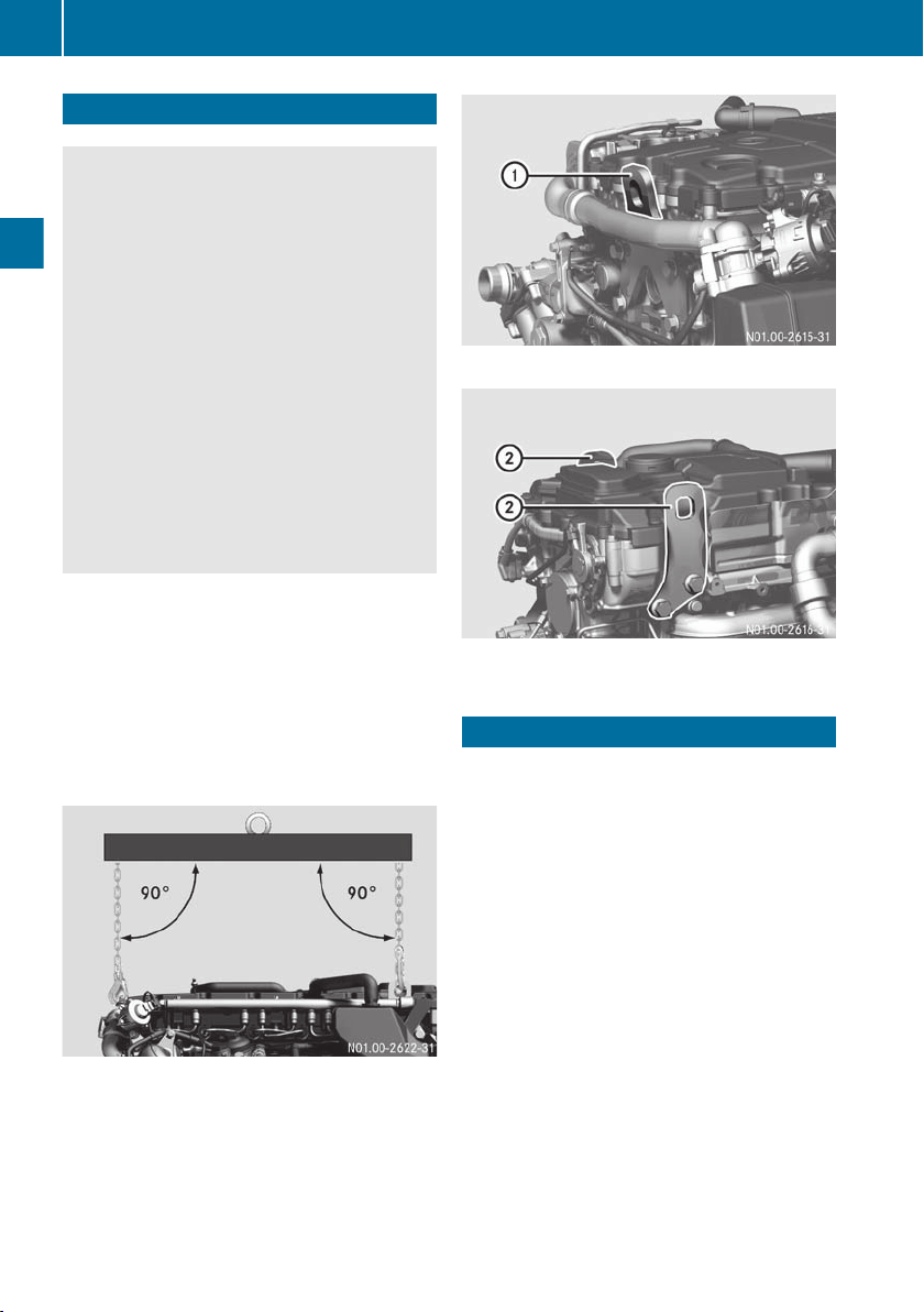
Example: using a cross member
The engine may only be lifted using a cross
member with the chain/rope at 90° relative
to the horizontal engine.
:
Example: belt-side lifting point
;
Example: flywheel-side lifting point
Installation
The engine system may only be installed as
contractually specified.
Observe the sections "Correct use" (Y page 8)
and "Modifying the engine output" (Y page 8).
Daimler AG provides the vehicle manufacturer with comprehensive material, e.g. the
installation guideline, for initial installation.
The vehicle manufacturer must take this into
account. If the engine is fitted after repair
work, for example, the information in the
Workshop Information System (WIS) must be
observed (Y page 10).
Observe the sections "Qualified specialist
workshop" (Y page 10) and "Further applicable documents" (Y page 10).
Please consult an MTU or MTU-authorised
Mercedes-Benz Service Centre (Y page 10) if
you have any questions. .
Page 31

Preparation for operation ................... 30
Starting and stopping the engine ...... 31
Switching the continuous brake on
and off .................................................. 33
Idling speed ......................................... 33
Operational monitoring ...................... 34
Displays ............................................... 35
Warning and indicator lamps ............. 36
Operating instructions ....................... 41
Refuelling ............................................. 43
Winter operation ................................. 45
29
Operation
Page 32
Preparation for operation
30
Preparation for operation
Engine with initial operation oil from the factory
The engine is filled at the factory with an initial
operation oil.
These high-quality engine oils are beneficial
to the running-in process. They also allow you
to make the first oil change in accordance
with the applicable oil change intervals. This
eliminates the need for special break-in oils
and the additional oil change otherwise
required.
Operation
Checking the engine oil level
The engine is equipped with an electronic oil
level detection system.
If the engine is also equipped with a dipstick,
this is subsidiary to the electronic oil level
measurement system. It is merely used for a
general check to determine if there is oil in the
engine.
Electronic oil level measurement – system description
The engine oil level sensor is installed in the
oil pan for oil level measurement. The electrical signals are detected in the engine management control module (MCM) and transmitted to the drive control system control unit
(CPC) via the engine CAN.
Output can be displayed on a matrix display
when the engine is not running.
The engine oil level is not displayed while the
engine is running.
possible with the engine switched off and the
ignition switched on.
X
Park the vehicle/device on a level surface.
X
Engage the parking brake.
X
Switch off the engine.
X
Wait approximately 5 to 10 minutes. If you
call up the oil level in the engine too early or
while the engine is running, it is not available.
Only use engine oil which has been approved
for the engine and which meets the specified
SAE classification (Y page 49).
Checking the oil level with the dipstick
Do not add too much oil. If you add too
!
much oil, the engine or the exhaust aftertreatment unit could be damaged. Drain or
siphon off any excess oil.
Check the engine oil level on a regular basis,
e.g. before each journey or each time you
refuel.
X
Park the vehicle/device on a level surface.
X
Engage the parking brake.
X
Switch off the engine.
X
Wait approximately 5 to 10 minutes.
Checking the oil level electronically
Check the engine oil level on a regular basis,
e.g. before each journey or each time you
refuel.
The current oil level in the engine is only displayed once the engine is switched off and
with the ignition switched on. An accurate
display of the engine oil level is therefore only
Page 33

X
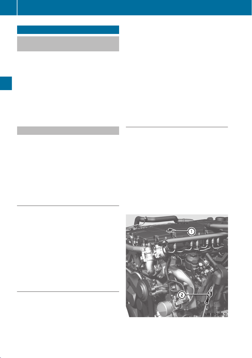
Check the engine oil level with dipstick ;.
The oil level should be between the upper
and lower marks on dipstick ;.
X
If necessary, use filler neck : to top up the
oil.
Only use engine oil which has been approved
for the engine and which meets the specified
SAE classification (Y page 49).
Checking the coolant level
X
Check the coolant level as stated in the
vehicle's/equipment's Operating Instructions.
X
Fill the cooling system if necessary. Only
use coolant that has been approved for the
engine (Y page 51).
Checking the fuel level
For checking the fuel level on the fuel gauge,
see the vehicle's Operating Instructions.
Refuel if necessary (Y page 52).
Checking the AdBlue®/DEF supply
For checking the AdBlue®/DEF supply on the
AdBlue®/DEF gauge, see the vehicle's Operating Instructions. Refuel if necessary
(Y page 44).
Starting and stopping the engine
Starting the engine
WARNING
G
Combustion engines emit poisonous exhaust
gases such as carbon monoxide. Inhaling
these exhaust gases leads to poisoning. There
is a risk of fatal injury. Therefore never leave
the engine running in enclosed spaces without sufficient ventilation.
Starting and stopping the engine
If the oil pressure in the engine is too low,
!
a warning light lights up on the instrument
panel. The warning buzzer also sounds.
The operating safety of the engine is jeopardised. Switch off the engine immediately.
Do not pull away as soon as the engine starts.
Do not subject the equipment to high loads
immediately. Let the engine run in neutral for
a short time after starting, until there is sufficient engine oil pressure. Do not drive at
high engine speeds when the engine is cold.
This will prevent excessive wear and possible
engine failure.
Warm up the engine quickly by driving at
moderate engine speeds. Depending on the
outside temperature, the engine will reach its
operating temperature after around 10 to
20 minutes. Operating temperature
(Y page 74).
You can utilise the full engine power output
once the engine has reached its normal operating temperature.
The display format for warning and indicator
lamps is vehicle-specific/equipment-specific. Observe the information contained in
the Operating Instructions for the vehicle/
equipment.
X
Start the engine using the key in the ignition
lock or the external engine start/engine
stop button on the engine. Do not depress
the accelerator or clutch pedal while doing
so.
For additional safety, the electronic engine
management system is equipped with a function that only allows the engine to be started
when the transmission is in neutral (vehicle/
equipment-specific).
Starting the engine with the key
After starting the engine, let it run at
!
engine idling speed until the oil pressure is
displayed. If no oil pressure is displayed
after approximately 10 seconds, switch off
the engine. Determine the cause. The operating safety of the engine is jeopardised.
31
Operation
Z
Page 34
Starting and stopping the engine
32
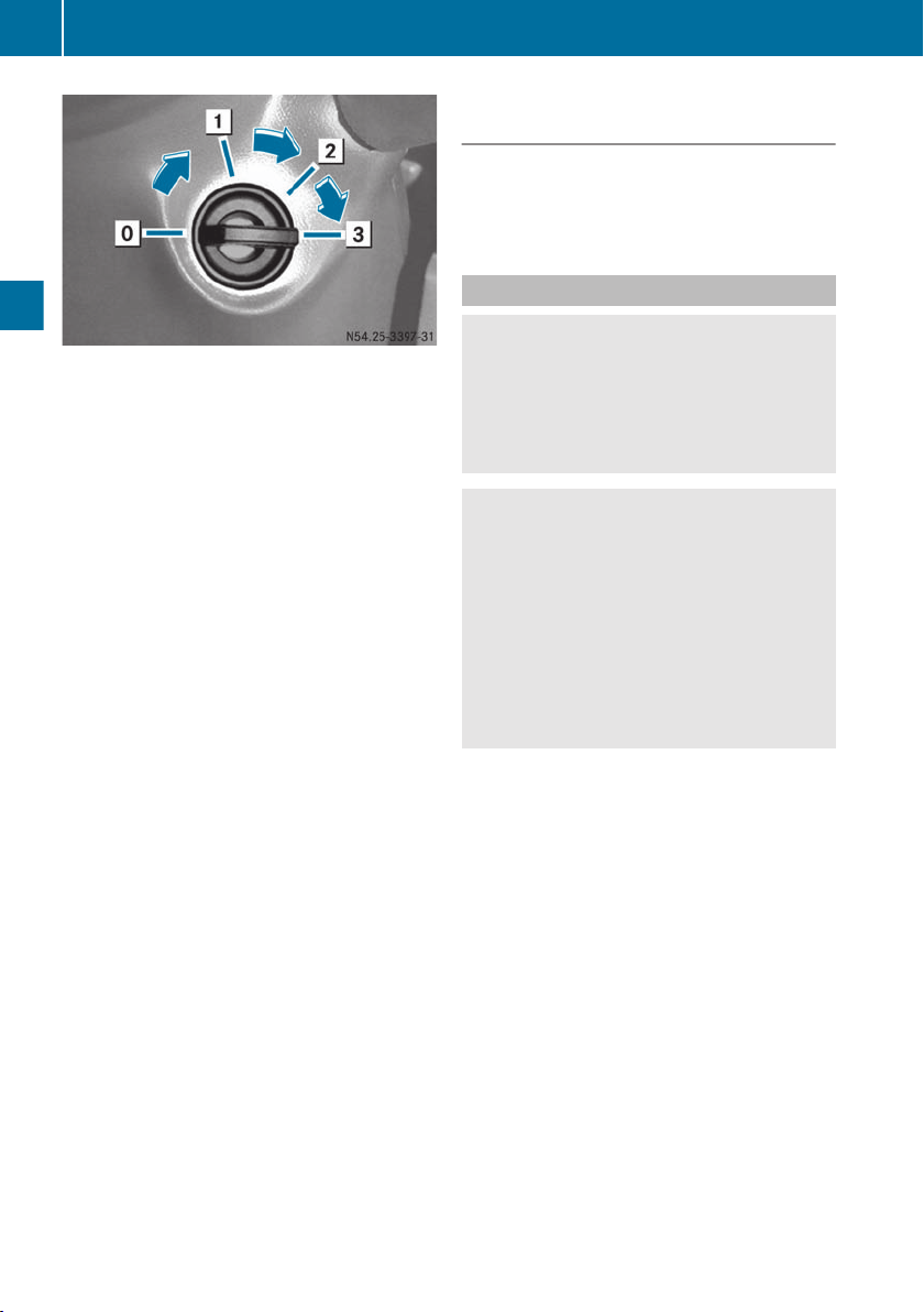
Example: ignition lock
g
To insert/remove the vehicle key
1
Steering wheel unlocked/radio position
2
Drive position (ignition)
Operation
3
Start position
X
Secure the vehicle/equipment against rolling away.
X
Deactivate power take-off.
X
Shift into neutral.
X
To start the engine: turn the key in the
ignition lock to drive position 2.
X
Turn the key to start position 3 in the ignition lock. Do not depress the accelerator
pedal whilst doing so.
X
When the engine has started, release the
key.
The idling speed is controlled automatically.
The engine idling speed is raised at very
i
low outside temperatures or during regeneration of the diesel particle filter.
X
If the engine does not start immediately: interrupt the starting procedure
after no more than 30 seconds.
X
Turn the key in the ignition lock back to the
stop at key position g.
X
Repeat the starting procedure after a waiting period of approximately 1 minute.
X
If the engine fails to start: rectify the cause
of the poor starting characteristics
(Y page 65).
X
Observe the oil pressure gauge immediately after having started the engine.
Starting the engine with the external
engine start/engine stop button
X
To start the engine with the external
engine start/engine stop button:
(Y page 60).
Stopping the engine
WARNING
G
When switching off the equipment or parking
the vehicle, make sure that the exhaust system does not come into contact with combustible objects, e.g. dry leaves, grass or
other highly flammable materials.
WARNING
G
If you switch off the ignition while the vehicle
is in motion, safety-relevant functions are
restricted or not available. This can affect the
power steering function and the brake boosting effect, for example. You will then require
considerably more force to steer and brake.
There is a risk of an accident.
Do not switch off the ignition while the vehicle
is in motion.
Stop the engine immediately, paying
!
attention to the road and traffic conditions
if:
R
the oil pressure falls or fluctuates significantly.
R
the power output or engine speed
decreases and the position of the position sensor (accelerator) remains constant.
R
heavy smoke is emitted from the
exhaust.
R
the coolant or engine oil temperature
rises steeply.
R
abnormal noises suddenly come from
the engine or exhaust gas turbocharger.
Page 35

X
Park the vehicle/equipment.
X
Secure the vehicle/equipment against rolling away.
X
Shift the transmission into neutral/decouple the drive system.
Let the engine idle for approximately 2
minutes before switching off the engine if:
R
the coolant temperature is very high (over
100 †).
R
the engine has been operated at full output.
X
To switch off the engine: turn the vehicle
key in the ignition lock back to the stop at
position u.
If you switch off the engine, the system
i
may continue to run for a short while.
Depending on the installation position,
operating state and ambient temperature,
circulation of AdBlue®/DEF is necessary
for ensuring cooling. To do this the
AdBlue®/DEF delivery pump is actuated
during this period.
Switching off the engine with the external engine start/engine stop button
X
To switch off the engine with the external engine start/engine stop button:
(Y page 60).
Switching the continuous brake on and off
WARNING
G
If you activate the continuous brake or shift to
a lower gear on a slippery road surface in
order to increase the engine's braking effect,
the drive wheels may lose traction. There is an
increased risk of skidding and an accident.
Do not activate the continuous brake and do
not shift to a lower gear in order to increase
the engine's braking effect on a slippery road
surface.
Idling speed
The engine brake and retarder are used as a
continuous brake.
You can utilise the engine's braking effect,
particularly on long downhill gradients if you:
R
activate the continuous brake
R
shift to a lower gear in good time
Slowly depress the brake pedal if the engine's
braking effect is insufficient when driving
downhill.
Vehicles without a retarder are equipped with
only two brake stages.
Operation of the continuous brake; see the
vehicle's Operating Instructions.
The à indicator lamp in the instrument
cluster is lit when the continuous brake is
active.
When ABS (Anti-lock Braking System) intervenes, the continuous brake is switched off.
The à indicator lamp in the instrument
cluster remains on.
Engine brake
The effectiveness of the engine brake
depends on the engine speed. A high engine
speed results in more effective engine braking.
Observe the effective engine braking range
marked on the rev counter (Y page 35).
At very low outside temperatures, the engine
brake has limited or no effect after the engine
has been started.
Operation of the engine brake; see the vehicle's Operating Instructions.
Retarder
Operation of the retarder; see the vehicle's
Operating Instructions.
Idling speed
After the engine has been started, idling
speed is regulated automatically. The engine
33
Operation
Z
Page 36

Operational monitoring
34
idling speed may differ in certain operating
conditions depending on the engine or on
vehicles with power take-off.
The engine idling speed for the 6R1000
engine can be set between approximately
600 and 800 rpm. For the 4R 1000 engine,
the engine idling speed can be set between
approximately 680 rpm and 800 rpm.
The engine idling speed is raised at very low
outside temperatures or during regeneration
of the diesel particle filter.
You can set the speed to the working speed
via the electronic engine management system. This makes it possible to drive auxiliary
equipment such as pumps at their working
Operation
speed. For setting the working speed, see the
vehicle's Operating Instructions.
Operational monitoring
Charge current
The charge current indicator lamp must go
out after the engine has started.
If the # indicator lamp does not go off or
lights up when the engine is running, switch
off the engine. Searching for and eliminating
the cause of the malfunction (Y page 65).
Electronic engine management
The indicator and warning lamps must go out
after the engine has started.
If an indicator lamp or warning lamp does not
go out, or if it lights up while the engine is
running, there is a malfunction in the electronic engine management system.
Each malfunction is stored in the system with
its own fault code. Temporary faults are also
stored.
Fault codes can be read by a qualified specialist workshop using a diagnostic tester
(Y page 8).
Oil pressure
If the 1 indicator lamp does not go out or
if it lights up when the engine is running,
switch off the engine. Searching for and eliminating the cause of the malfunction
(Y page 65).
Operating restrictions
The electronic engine management system
monitors:
R
emissions-relevant malfunctions in the
exhaust gas aftertreatment
R
malfunctions in the electronic monitoring
of the exhaust gas aftertreatment system
R
consumption, level and quality of the
AdBlue®/DEF reducing agent
R
the efficiency of the catalytic converter in
accordance with the permitted thresholds
for nitric oxide emissions (NOx)
Operating restrictions in the form of torque
reduction and thus output and speed limitation may occur.
Emergency switch for overriding the operating restrictions
If an emissions-related malfunction of the
exhaust gas aftertreatment system or
AdBlue®/DEF supply is detected, this can
lead to operating restrictions (engine torque
and engine speed limitation).
In emergencies, a push-button switch can be
operated to override the operating restriction. This means that full engine power is
available for a maximum of 30 minutes. This
emergency function by operating the switch
can be activated a maximum of three times.
If the final operating restriction (idling speed
and 20% of torque) has been reached, the
push-button switch is deactivated.
Page 37

Displays
35
Displays
Rev counter
If you exceed the maximum permissible
!
engine speed, the warning tone sounds.
You should not drive and change gear by
the sound of the engine, but according to
the engine speed shown in the rev counter.
Avoid driving in the red overrevving range.
This could lead to engine damage.
The engine speed display is the responsibility
of the vehicle manufacturer and is not necessarily supplied by Mercedes-Benz. Daimler
AG recommends that the vehicle manufacturer uses a rev counter divided by:
R
operational efficiency
R
engine braking range
R
engine overrevving range
General notes on the rev counter:
R
Keep an eye on the rev counter while driving and stay within the economical operating range.
In some situations it may make sense to
operate the engine outside the economical
engine speed range, e.g. on uphill gradients
or when overtaking.
R
If you run the engine within the economical
engine speed range, you achieve low fuel
consumption and reduced wear.
R
In engine braking mode, drive in the middle
engine speed range. The highest engine
braking effect will be achieved just before
the red overrevving range.
R
When driving downhill, make sure that the
engine speed does not enter the overrevving range (marked red).
R
Idling speed is set automatically depending
on the coolant temperature.
R
When the vehicle is stationary, the engine is
running and the transmission is in neutral,
the engine increases throttle only slowly.
AdBlue®/DEF level
The AdBlue®/DEF gauge is the responsibility
of the vehicle manufacturer. It is not necessarily supplied by Mercedes-Benz. Daimler
AG recommends that the vehicle manufacturer uses an AdBlue®/DEF gauge and an
AdBlue®/DEF indicator lamp for the
AdBlue®/DEF reserve level Ø.
The AdBlue®/DEF reducing agent is required
for reduction of engine emissions.
The operating permit is invalidated if the vehicle is operated without AdBlue®/DEF. The
legal consequence of this is that the vehicle
may no longer be operated on public roads.
If the AdBlue®/DEF level has sunk to approximately 10 %, a warning lamp for the
AdBlue®/DEF reserve level lights up on the
instrument panel. Top up the AdBlue®/DEF
tank in good time (Y page 44).
If the gauge is ignored and the AdBlue®/DEF
level drops further, engine torque and engine
speed may be reduced.
Engine torque may be limited to a maximum
of 20% across the whole engine speed range.
Engine speed may be limited to idling speed.
Operation
Z
Page 38

Warning and indicator lamps
36
Warning and indicator lamps
Warning and indicator lamps - causes/consequences and solutions
Problem
The indicator lamp
flashes red.
Possible causes/consequences and M Solutions
A serious fault in the engine system has been detected.
X
Immediately stop the vehicle/equipment while paying attention
to the traffic conditions and contact a qualified specialist workshop.
The Ù indicator
lamp lights up.
Impermissible operating conditions have been detected in the
engine system.
One of the following systems is malfunctioning:
R
Operation
Engine
R
Engine cooling
R
Engine management
R
Diesel injection system
X
If further indicator lamps are displayed, take the combination of
lamps (see below) into account when evaluating the cause.
X
Have the systems checked at a qualified specialist workshop.
Only vehicles/equipment with the AdBlue®/DEF reserve warning light
If a malfunction is detected and the listed indicator lamps light up, a warning buzzer sounds for
approximately 5 seconds. In emergencies, operating restrictions (engine torque and engine
speed restrictions) can be temporarily overridden with the emergency switch (Y page 34).
Page 39
Warning and indicator lamps
37
Problem
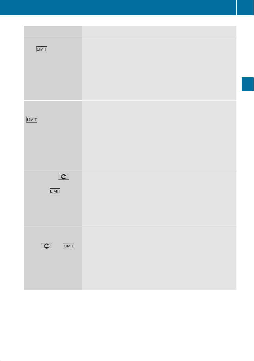
Indicator lamps Ø
and are lit and
· flashes.
The Ø indicator
lamp is lit and · and
are flashing.
The Ø and indi-
cator lamps are lit and
· and are
flashing.
Possible causes/consequences and M Solutions
The AdBlue®/DEF level has dropped to approximately 7.5%.
Reduced engine output is active. The engine torque is limited to a
maximum of 75% across the whole engine speed range. The limitation takes effect by means of a ramp function.
X
Adapt your driving/operating style.
X
Top up the AdBlue®/DEF tank immediately.
If you do not follow the instructions, the engine speed may be
limited.
The AdBlue®/DEF level has dropped to approximately 5%.
Reduced engine output and engine speed limitation are active. The
engine torque is limited to a maximum of 50% across the whole
engine speed range. The engine speed is limited to a maximum of
60%. The limitation takes effect by means of a ramp function.
X
Adapt your driving/operating style.
X
Top up the AdBlue®/DEF tank immediately.
If you do not observe the instructions, engine torque and engine
speed may be reduced further.
The AdBlue®/DEF level has dropped to approximately 2.5%.
Reduced engine output and engine speed limitation are active. The
engine torque is limited to a maximum of 20% across the whole
engine speed range. The engine speed is limited to idling speed.
The limitation takes effect by means of a ramp function.
X
Adapt your driving/operating style.
X
Top up the AdBlue®/DEF tank immediately.
Operation
The Ø indicator
lamp lights up and
·, and
are flashing.
The AdBlue®/DEF level has dropped to approximately 0%.
Reduced engine output and engine speed limitation are active. The
engine torque is limited to a maximum of 20% across the whole
engine speed range. The engine speed is limited to idling speed.
The limitation takes effect by means of a ramp function.
X
Stop the vehicle/equipment, paying attention to road and traffic
conditions.
X
Top up the AdBlue®/DEF tank immediately.
Z
Page 40

Warning and indicator lamps
38
Problem
The · indicator
lamp lights up.
The indicator lamp
lights up and · is
flashing.
Operation
The and · indi-
cator lamps are flashing.
Possible causes/consequences and M Solutions
An emissions-relevant malfunction in the exhaust gas aftertreatment system or in the AdBlue®/DEF supply has been detected.
X
Have the exhaust gas aftertreatment system checked at a qualified specialist workshop. Have the malfunction rectified immediately. If you do not, engine output may be reduced and engine
speed may be limited.
If there are no malfunctions, the indicator lamp only goes out after
further test routines. The system check may involve several engine
starts, several hours or several journeys without a malfunction.
You have not rectified an emissions-relevant malfunction that has
been detected in the exhaust gas aftertreatment system or in the
AdBlue®/DEF supply.
Reduced engine output is active. The engine torque is limited to a
maximum of 75% across the whole engine speed range. The limitation takes effect by means of a ramp function.
X
Adapt your driving/operating style.
X
Drive carefully to the nearest qualified specialist workshop and
have the malfunction rectified immediately.
If you do not follow the instructions, engine speed may be limited.
You have not rectified an emissions-relevant malfunction that has
been detected in the exhaust gas aftertreatment system or in the
AdBlue®/DEF supply.
Reduced engine output and engine speed limitation are active. The
engine torque is limited to a maximum of 50% across the whole
engine speed range. The engine speed is limited to a maximum of
60%. The limitation takes effect by means of a ramp function.
X
Adapt your driving/operating style.
X
Drive carefully to the nearest qualified specialist workshop and
have the malfunction rectified immediately.
If you do not follow the instructions, further engine speed limitation may be imposed.
Page 41
Warning and indicator lamps
39
Problem
The and · indi-
cator lamps are flash-
ing and lights up.
Possible causes/consequences and M Solutions
You have not rectified an emissions-relevant malfunction that has
been detected in the exhaust gas aftertreatment system or in the
AdBlue®/DEF supply.
Reduced engine output and engine speed limitation are active. The
engine torque is limited to a maximum of 20% across the whole
engine speed range. The engine speed is limited to idling speed.
X
Adapt your driving/operating style.
X
Have the malfunction rectified immediately at a specialist workshop.
The , · and
indicator lamps
are flashing.
You have not rectified an emissions-relevant malfunction that has
been detected in the exhaust gas aftertreatment system or in the
AdBlue®/DEF supply.
Reduced engine output is active. The engine torque is limited to a
maximum of 20% across the whole engine speed range. The engine
speed is limited to idling speed.
X
Stop the vehicle/equipment, paying attention to road and traffic
conditions.
X
Have the malfunction rectified immediately at a specialist workshop.
When the AdBlue®/DEF tank is filled or the fault is rectified, full engine power will be available
again. If the system check does not detect any other faults, the indicator lamps go out after the
system's status indicator. The system check may involve several engine starts, several hours
or several journeys without a malfunction.
Operation
Only vehicles/equipment without the AdBlue®/DEF reserve warning light
If a malfunction is detected and the listed indicator lamps light up, a warning buzzer sounds for
approximately 5 seconds. In emergencies, operating restrictions (engine torque and engine
speed restrictions) can be temporarily overridden with the emergency switch (Y page 34).
Z
Page 42

Warning and indicator lamps
40
Problem
The · indicator
lamp lights up.
The · indicator
lamp is flashing and
Operation
lights up.
The · and indi-
cator lamps are flashing.
Possible causes/consequences and M Solutions
An emissions-relevant malfunction in the exhaust gas aftertreatment system or in the AdBlue®/DEF supply has been detected.
X
Top up the AdBlue®/DEF tank immediately.
X
If this does not help: have the exhaust gas aftertreatment system checked at a qualified specialist workshop. Have the malfunction rectified immediately. If you do not, engine output may
be reduced and engine speed may be limited.
If there are no malfunctions, the indicator lamp only goes out after
further test routines. The system check may involve several engine
starts, several hours or several journeys without a malfunction.
You have not rectified an emissions-relevant malfunction that has
been detected in the exhaust gas aftertreatment system or in the
AdBlue®/DEF supply.
Reduced engine output is active. The engine torque is limited to a
maximum of 75% across the whole engine speed range. The limitation will take effect the next time the engine is started.
X
Adapt your driving/operating style.
X
Top up the AdBlue®/DEF tank immediately.
X
If this does not help: have the malfunction rectified at a qualified
specialist workshop.
If you do not follow the instructions, engine speed may be limited.
You have not rectified an emissions-relevant malfunction that has
been detected in the exhaust gas aftertreatment system or in the
AdBlue®/DEF supply.
Reduced engine output and engine speed limitation are active. The
engine torque is limited to a maximum of 50% across the whole
engine speed range. The engine speed is limited to a maximum of
60%. The limitation will take effect by means of a ramp function.
X
Adapt your driving/operating style.
X
Top up the AdBlue®/DEF tank immediately.
X
If this does not help: have the malfunction rectified at a qualified
specialist workshop.
If you do not follow the instructions, further engine speed limitation may be imposed.
Page 43
Operating instructions
41
Problem
The · and indi-
cator lamps are flash-
ing and lights up.
Possible causes/consequences and M Solutions
You have not rectified an emissions-relevant malfunction that has
been detected in the exhaust gas aftertreatment system or in the
AdBlue®/DEF supply.
Reduced engine output and engine speed limitation are active. The
engine torque is limited to a maximum of 20% across the whole
engine speed range. The engine speed is limited to idling speed.
X
Adapt your driving/operating style.
X
Top up the AdBlue®/DEF tank immediately.
X
If this does not help: have the malfunction rectified at a qualified
specialist workshop.
The ·, and
indicator lamps
are flashing.
You have not rectified an emissions-relevant malfunction that has
been detected in the exhaust gas aftertreatment system or in the
AdBlue®/DEF supply.
Reduced engine output and engine speed limitation are active. The
engine torque is limited to a maximum of 20% across the whole
engine speed range. The engine speed is limited to idling speed.
X
Stop the vehicle/equipment, paying attention to road and traffic
conditions.
X
Have the malfunction rectified at a specialist workshop.
When the AdBlue®/DEF tank is filled or the fault is rectified, full engine power will be available
again. If the system check does not detect any other faults, the indicator lamps go out after the
system's status indicator. The system check may involve several engine starts, several hours
or several journeys without a malfunction.
Operation
Operating instructions
Running-in
The running-in period of the engine has a significant effect on the vehicle/equipment,
especially with regard to:
R
service life
R
operating safety
R
economy
Observe the following notes during the running-in period up to 2000 km (30 operating
hours):
R
avoid subjecting the engine to full load.
R
run in the engine with care, using differing
speeds and engine revs.
R
avoid high engine speeds.
R
do not drive at more than ¾ of the maximum road speed for each gear.
R
change gear in good time.
R
do not shift down to brake the vehicle.
R
for vehicles with automatic transmission,
do not depress the accelerator pedal
beyond the point of resistance (kickdown).
After 2,000 km (30 operating hours), you can
gradually bring the vehicle/equipment up to
full output and increased engine speeds.
Z
Page 44

Operating instructions
42
Fuel consumption
General notes
Fuel consumption depends on:
R
the machine version/vehicle version
R
the operating conditions
R
the attached equipment (e.g. hydraulic
pumps, mowers, etc.)
R
the fuel type in use
R
maintenance
R
driving resistance
R
your driving style
For these reasons, exact details about any
Operation
single engine's fuel consumption cannot be
provided.
Machine version/vehicle version
The following components affect fuel consumption:
R
tyres (e.g. tyre pressure, tyre condition)
R
body type
R
drive train (e.g. transmission ratio)
R
additional equipment (e.g. automatic climate control, auxiliary heating)
Maintenance
The fuel consumption and assembly wear
depend on regular maintenance. Regular
maintenance increases safety and lowers fuel
consumption. Keep to the maintenance intervals. Always have maintenance work carried
out at a qualified specialist workshop.
Fuel type
The fuel grade also affects fuel consumption.
Use of lower fuel grades and/or nonapproved fuel additives will increase fuel consumption. When refuelling, ensure that you
are filling the appropriate fuel grade
(Y page 52).
AdBlue®/DEF consumption
AdBlue® consumption is between 2 and 4% of
the fuel consumption, depending on engine
use.
Engine oil consumption
After running-in the engine, oil consumption
may reach 0.2 % of the vehicle's fuel consumption.
More arduous operating conditions and
increased distance covered could result in
engines exceeding this oil consumption
value.
Warning buzzer
If the warning buzzer sounds and the 5
symbol on the instrument panel is displayed,
the engine's operating safety is jeopardised.
Do not pull away, or stop the vehicle as soon
as possible, paying attention to road and traffic conditions. You could otherwise damage
the engine.
The warning buzzer sounds depending on the
vehicle if:
R
you exceed the maximum permissible
engine speed
R
the engine speed or vehicle speed is too
high when changing gears
R
the coolant level is too low or the maximum
permissible coolant temperature (approximately 112 †) is exceeded. The operating
safety of the engine is jeopardised.
R
an emissions-relevant error is detected or
there is an operating restriction due to an
emissions-relevant malfunction.
Page 45

Refuelling
Fuels
Important safety notes
WARNING
G
Fuels are poisonous and hazardous to health.
There is a danger of injury.
Do not swallow fuel or let it come into contact
with skin, eyes or clothing. Do not inhale fuel
vapours. Keep fuels out of the reach of children.
If you or others come into contact with fuel,
observe the following:
R
Wash the fuel off any affected areas of skin
with water and soap immediately.
R
If you get fuel in your eyes, rinse them thoroughly with clean water immediately. Seek
immediate medical attention.
R
If fuel is swallowed, seek immediate medical attention. Do not induce vomiting.
R
Change any clothing that has come into
contact with fuel immediately.
WARNING
G
Fuel is highly flammable. Improper handing of
fuel creates a risk of fire and explosion.
Avoid fire, naked flames, smoking and creating sparks under all circumstances. Switch off
the ignition and auxiliary heating before carrying out work to the fuel system. Always wear
protective gloves.
WARNING
G
If you mix diesel fuel with petrol, the flash
point of this fuel mixture is lower than that of
pure diesel fuel. When the engine is running,
components in the exhaust system may overheat unnoticed. There is a risk of fire.
Never refuel with petrol. Never add petrol to
diesel fuel.
Refuelling
Only refuel using commercially available,
!
sulphur-free diesel fuel that complies with
the following standards:
R
EN 590 as of 2010, et seq. (max. 0.001%
sulphur by weight) (10 ppm) or
R
ASTM D975 (max. 0.0015% sulphur by
weight) (15 ppm).
The following fuel types are not permitted:
R
sulphurous fuel with a sulphur content
greater than 0.005% by weight (50 ppm)
R
marine diesel fuel
R
aviation turbine fuel
R
heating oils
R
fatty acid methyl ester FAME (bio-diesel
fuel)
These fuel types cause irreversible damage
to the engine and the exhaust gas aftertreatment system, as well as also significantly reducing the expected service life.
Do not use petrol to refuel vehicles with a
!
diesel engine. Even small amounts of petrol
result in damage to the fuel system and
engine.
Do not switch on the ignition if you acci-
!
dentally refuel with the wrong fuel. Otherwise, the fuel will enter the fuel lines. Notify
a qualified specialist workshop and have
the fuel tank and fuel lines drained completely.
Do not add any special fuel additives to
!
the diesel fuel.
Special fuel additives can lead to:
R
malfunctions
R
damage to the catalytic converter
R
engine damage
AdBlue®/DEF is not a fuel additive and
!
must not be added to the diesel tank. If
AdBlue®/DEF gets into the diesel tank, this
could lead to engine damage.
A higher fuel sulphur content accelerates
!
the ageing process of the engine oil and can
damage the engine and exhaust system.
43
Operation
Z
Page 46

Refuelling
44
Environmental note
H
If fuels are handled improperly, they pose a
danger to persons and the environment. Do
not allow fuels to run into the sewage system,
the surface waters, the ground water or into
the ground.
You will find further information on fuel in the
"Service products" section (Y page 52).
Before filling the tank
If you are using drums or canisters to
!
refuel the vehicle, you should filter the fuel
before adding it.
Operation
This will prevent malfunctions in the fuel
system due to contaminated fuel.
X
Switch off the engine.
X
Secure the vehicle/equipment against rolling away.
X
Observe the fuel grade (Y page 52).
Regularly check the fuel prefilter with heated
water separator for condensation.
AdBlue®/DEF
Important safety notes
Do not allow diesel fuel to run into the
!
AdBlue®/DEF tank. You could otherwise
damage the exhaust gas aftertreatment
system.
Only use AdBlue®/DEF in accordance
!
with DIN 70070/ISO 22241. Do not use
any additives.
If AdBlue®/DEF comes into contact with
painted or aluminium surfaces when filling
the tank, rinse the affected area immediately with plenty of water.
Do not mix additives to AdBlue®/DEF. Do
!
not dilute AdBlue®/DEF with tap water.
This could destroy the exhaust gas aftertreatment system.
Always close the AdBlue®/DEF tank
!
properly. Otherwise impurities may get into
the exhaust gas aftertreatment system and
damage it.
Make sure that you do not overfill the
!
AdBlue®/DEF tank. Otherwise, the
AdBlue®/DEF tank could be damaged at
very low temperatures.
Environmental note
H
Dispose of AdBlue®/DEF in an environmentally responsible manner.
When opening the AdBlue®/DEF tank, small
amounts of ammonia vapours could escape.
Ammonia vapours have a pungent smell and
are particularly irritating to:
R
skin
R
mucous membranes
R
eyes
The vapours may cause a burning sensation in
the eyes, nose and throat as well as irritation
of the throat and watering eyes.
Avoid inhaling ammonia vapours. Only fill the
AdBlue®/DEF tank in well-ventilated areas.
AdBlue®/DEF should not come into contact
with skin, eyes or clothing, and should not be
swallowed. Keep AdBlue®/DEF out of the
reach of children.
If you come into contact with AdBlue®/DEF,
observe the following:
R
immediately wash AdBlue®/DEF from your
skin with water and soap.
R
if AdBlue®/DEF comes into contact with
your eyes, rinse your eyes with clean water
immediately. Seek medical attention
immediately.
R
if you have swallowed AdBlue®/DEF,
immediately rinse your mouth with water
and drink plenty of water. Seek medical
attention immediately.
R
change clothing that has come into contact
with AdBlue®/DEF immediately.
Page 47

Winter operation
45
AdBlue®/DEF is not refilled as part of the
maintenance work. Top up the tank regularly
during vehicle operation or at the latest when
the first event message is displayed on the
electronic engine management system.
You will find further information on AdBlue®/
DEF in the "Service products" section
(Y page 53).
Before filling the tank
X
Switch off the engine.
X
Secure the vehicle/equipment against rolling away.
Always fill the tank with at least 5 litres, as
smaller amounts could cause malfunctions.
Winter operation
At very low outside temperatures, make
!
sure that the engine oil added is of an
appropriate SAE classification. Using
engine oils that are not suitable for very low
outside temperatures may result in engine
damage.
Before the start of the cold season, make sure
that:
R
the coolant contains sufficient antifreeze
(Y page 51)
R
the fuel used is suitable for winter use
(Y page 52)
R
the SAE class of the engine oil used is in
accordance with outside temperatures
(Y page 49).
Batteries
Always aim to achieve the full charge status.
You can do this by means of careful maintenance and low electrical consumption. The
cold start capacity is reduced when it is very
cold. For example, at -10 † it is only around
60 % of the normal capacity.
Diesel fuels
Notes on diesel fuel at low temperatures
(Y page 52).
Operation
Jump-starting
WARNING
G
The use of liquid or gaseous starting aids can
cause explosions. This may result in severe
injuries.
Do not use liquid or gaseous starting aids
such as ether or Startpilot to start the engine.
Z
Page 48

46
Page 49

General notes ...................................... 48
Service products ................................. 49
Cleaning and care ............................... 55
47
Maintenance
Page 50

General notes
48
General notes
WARNING
G
Before carrying out maintenance or repair
work, you must read the relevant sections of
the technical documentation relating to maintenance and repair measures, e.g. the Operating Instructions and workshop information.
In particular, first familiarise yourself with the
legal regulations, e.g. work safety and accident prevention regulations.
You could otherwise fail to recognise dangers
and injure yourself or others.
Always have maintenance work carried out at
a qualified specialist workshop.
WARNING
G
If you do not have the prescribed service/
Maintenance
maintenance work or necessary repairs carried out, this could result in malfunctions or
system failures. There is a risk of an accident.
Always have the prescribed service/maintenance work as well as necessary repairs carried out at a qualified specialist workshop.
WARNING
G
Limbs could be crushed or trapped if the
engine is started unintentionally during service or maintenance work. There is a risk of
injury.
Always secure the engine against unintentional starting before carrying out maintenance or repair work.
WARNING
G
Cloths or other flammable materials left in the
engine compartment can ignite if they come
into contact with the exhaust system or parts
of the engine that heat up. There is a risk of
fire. After carrying out maintenance work,
make sure that no extraneous flammable
material is left in the engine compartment or
on the exhaust system.
Environmental note
H
If circumstances require you to do some maintenance work yourself, you must observe the
environmental protection requirements.
When disposing of service products, e.g.
engine oil, you must comply with the legal
requirements. This also concerns all parts,
e.g. filters, that have been in contact with service products.
Dispose of empty containers, cleaning cloths
and care products in an environmentally
responsible manner.
Observe the instructions for care products.
Do not let the engine run longer than necessary when stationary.
Like all technical equipment, the engine system requires care and maintenance.
The scope and frequency of maintenance
work depends mainly on:
R
the widely varying operating conditions.
R
the service products used.
All maintenance intervals and work refer
i
to genuine Mercedes-Benz parts. They also
refer to accessory parts and service products that have been expressly approved by
Mercedes-Benz for the engine.
Inspection and maintenance work requires
special skills that cannot be acquired by reading these Operating Instructions. Always have
this work and maintenance work carried out
by a qualified specialist workshop.
Have any work that is carried out confirmed
with an entry in the Maintenance Booklet.
This proof of regular maintenance is always
required for any warranty claims.
Instructions and important information on
carrying out maintenance work can be found
in the Workshop Information System (WIS) on
the Internet. Make sure that you have access
to this information when carrying out maintenance work. Information on WIS
(Y page 10).
Please also observe the maintenance instructions for special accessories.
Page 51

Service products
49
When working on the vehicle, comply with all
safety regulations, such as operating instructions, regulations concerning hazardous
materials, environmental protection measures, work safety and accident prevention
regulations.
Service products
Important safety notes
WARNING
G
Service product can be poisonous and hazardous to health. There is a risk of injury.
Observe the instructions on the respective
original container when using, storing and disposing off service products. Always store service products in the sealed original container.
Always keep service products out of the reach
of children.
Special additives (except approved fuel
!
additives) are neither required nor
approved for use with approved service
products. Additives may cause damage to
major assemblies. Therefore, do not mix
any additives with service products. You
are responsible for the results of using fuel
additives.
Environmental note
H
Dispose of service products in an environmentally-responsible manner.
Service products are:
R
fuels (e.g. diesel)
R
lubricants (e.g. engine oil, transmission oil,
grease)
R
coolant, antifreeze
R
AdBlue®/DEF, reducing agent in the
exhaust gas aftertreatment system
Approved service products fulfil the highest
quality standards and are documented in the
Mercedes-Benz Specifications for Service
Products. For this reason, only use approved
service products for your engine system.
Information about approved service products
is available from any MTU or MTU-authorised
Mercedes-Benz Service Centre (Y page 10).
You can recognise service products approved
by Mercedes-Benz by the following inscription on the container:
R
MB-Freigabe (e.g. MB-Freigabe 228.51)
or
R
MB-Approval (z. B. MB-Approval 228.51)
Other labels and recommendations relating
to the quality or indicating that the product
meets a certain specification are not necessarily approved by Mercedes-Benz. Further
information is available from any MTU or
MTU-authorised Mercedes-Benz Service
Centre (Y page 10).
Information about service products which
i
have been tested by Mercedes-Benz and
approved for your engine system can be
found in the Mercedes-Benz Specifications
for Service products on the Internet at:
http://bevo.mercedes-benz.com/.
The specification and availability of lubri-
i
cants may vary. Individual lubricants may
no longer be available, especially for older
engines. Information is available from any
MTU or MTU-authorised Mercedes-Benz
Service Centre (Y page 10).
Engine oils
Notes on engine oils
Engine oils other than those of the quality
!
specified in this Operator's Manual are not
permitted.
Only use engine oils in accordance with
Sheet No. 228.51, 228.31, 228.5 or 228.3 of
the Mercedes-Benz Specifications for Service
Products.
Maintenance
Z
Page 52
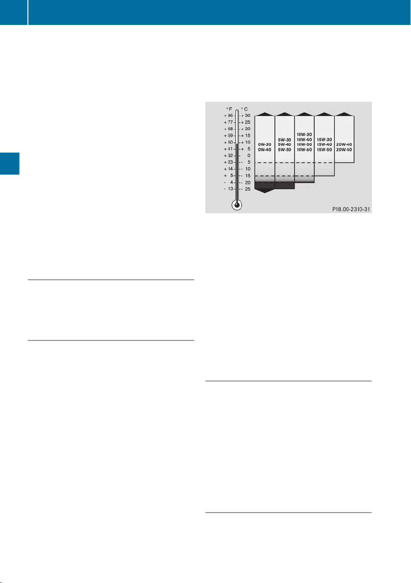
Service products
50
Engine oils according to Sheet No. 228.51
and 228.5 have a higher quality standard and
have a favourable effect on:
R
length of oil change intervals
R
engine wear
R
fuel consumption
R
exhaust emissions
You can find information on the quality
i
grade, e.g. Sheet No. 228.51, and the viscosity, e.g. SAE class 5W-30, from the designation on the oil container.
Before delivery, the engine is filled with oil in
SAE class 5W-30 (Y page 30).
Check the vehicle assemblies for leaks regularly. If fluid loss is identified, e.g. by oil drops
on the parking area, have the cause of the
fluid loss rectified at a qualified specialist
Maintenance
workshop.
Scope of application
Multi-grade engine oils compliant with Sheet
Nos. 228.51, 228.31, 228.5 or 228.3 can be
used all year round.
Oil change
If you mix engine oils with differing oil
!
grades, the change interval for the engine
oil is reduced in comparison to mixtures of
engine oil of identical grade.
Therefore, only mix engine oils of differing
grade in exceptional circumstances. To
prevent damage to the engine, the maintenance intervals must be adjusted accordingly.
If the SAE class (viscosity) of the engine
!
oil used is not suitable for continually low
outside temperatures below -20 †, this
could cause engine damage.
The specified temperatures of the SAE
class always refer to freshly added oil.
Engine oil ages during driving due to soot
and fuel residue. This impairs the characteristics of the engine oil, particularly at low
outside temperatures.
If the outside temperature is under -20 †,
Mercedes-Benz strongly recommends
using engine oils of SAE class 5W-30 or
0W-30.
Use only all-season oils.
Engine oil SAE classes (viscosity)
Oil change intervals are dependent on the following:
R
the operating conditions of the vehicle
R
the grade of the engine oil used
The maximum oil change interval can only be
achieved by using engine oils of particularly
high quality in accordance with Sheet No.
228.51 and 228.5 of the Mercedes-Benz
Specifications for Service Products. The classification of oil change intervals is specified in
the Maintenance Booklet.
Adding/topping up the engine oil
There is a risk of damage to the catalytic
!
converter or to the engine if too much oil is
added. Have excess oil drained off.
When topping up, Mercedes-Benz recommends that you only use engine oil of the
same grade and SAE class as the oil filled at
the last oil change.
Check the oil level before topping up the
engine oil (Y page 30).
Miscibility of engine oils
The benefits of high-quality engine oils are
diminished if you mix them.
Page 53

Service products
51
Engine oils are differentiated according to:
R
engine oil brand
R
quality grade (Sheet No.)
R
SAE viscosity class
If, in exceptional circumstances, the type of
engine oil currently used in the engine is not
available, another mineral or synthetic engine
oil may be used. Make sure it is approved for
Mercedes-Benz.
Please observe the following: if you top up
with an engine oil of a lower quality, the maintenance interval must be adapted to the lower
quality (Sheet No.). The maintenance interval
is reduced. If you top up with an engine oil of
a higher quality, the maintenance interval is
not altered.
Observe the notes in the Maintenance Booklet.
Coolant
WARNING
G
The engine cooling system is under pressure,
particularly if the engine is warm. You could
be scalded by hot coolant spraying out when
opening the cap. There is a danger of injury.
Allow the engine to cool before opening the
cap. Wear gloves and protective eyewear
when opening. Slowly turn the cap half a turn
to allow pressure to escape.
WARNING
G
If antifreeze comes into contact with hot components in the engine compartment, it may
ignite. There is a risk of fire and injury.
Let the engine cool down before you top up
the antifreeze. Make sure that antifreeze is
not spilled next to the filler neck. Thoroughly
clean the antifreeze from components before
starting the engine.
A coolant that ensures anti-corrosion/antifreeze protection and other important protective effects is filled at the factory.
The coolant is a mixture of water and corrosion inhibitor/antifreeze.
The corrosion inhibitor/antifreeze in the coolant has the following properties:
R
heat transfer
R
anti-corrosion protection
R
cavitation protection (protection against
pitting)
R
antifreeze protection
R
raising the boiling point
Leave the coolant in the engine cooling system all year round – even in countries with
high outside temperatures.
Check the corrosion inhibitor/antifreeze concentration in the coolant every six months.
Renew the coolant at the interval specified in
the Maintenance Booklet.
Use only approved corrosion inhibitor/antifreeze additives according to Sheet No.325.5
and 326.5. This prevents damage to the
engine cooling system and engine.
When renewing the coolant, ensure that it
contains 50% corrosion inhibitor/antifreeze
by volume. This corresponds to antifreeze
protection down to Ò37 †.
Do not exceed 55% by volume (antifreeze
down to approximately Ò45 †). The heat dissipation and antifreeze may otherwise be
negatively affected.
If there is a loss of coolant, do not top it up by
using only water, but also add an approved
corrosion inhibitor/antifreeze agent.
The water in the coolant must meet certain
requirements, which are often fulfilled by the
use of drinking water. The water must be
treated if its quality does not meet the
required standards.
Please note the Mercedes-Benz Specifications for Service Products, Sheet No. 310.1.
Mixtures with other corrosion inhibitors/antifreeze agents are not permitted.
Maintenance
Z
Page 54

Service products
52
Diesel fuels
Important safety notes
WARNING
G
Fuel is highly flammable. Improper handing of
fuel creates a risk of fire and explosion.
Avoid fire, naked flames, smoking and creating sparks under all circumstances. Switch off
the engine and, if applicable, the auxiliary
heating before refuelling.
WARNING
G
Fuels are poisonous and hazardous to health.
There is a danger of injury.
Do not swallow fuel or let it come into contact
with skin, eyes or clothing. Do not inhale fuel
vapours. Keep fuels out of the reach of children.
Maintenance
If you or others come into contact with fuel,
observe the following:
R
Wash the fuel off any affected areas of skin
with water and soap immediately.
R
If you get fuel in your eyes, rinse them thoroughly with clean water immediately. Seek
immediate medical attention.
R
If fuel is swallowed, seek immediate medical attention. Do not induce vomiting.
R
Change any clothing that has come into
contact with fuel immediately.
Only refuel using commercially available,
!
sulphur-free diesel fuel that complies with
the following standards:
R
EN 590 as of 2010, et seq. (max. 0.001%
sulphur by weight) (10 ppm) or
R
ASTM D975 (max. 0.0015% sulphur by
weight) (15 ppm).
The following fuel types are not permitted:
R
sulphurous fuel with a sulphur content
greater than 0.005% by weight (50 ppm)
R
marine diesel fuel
R
aviation turbine fuel
R
heating oils
R
fatty acid methyl ester FAME (bio-diesel
fuel)
These fuel types cause irreversible damage
to the engine and the exhaust gas aftertreatment system, as well as also significantly reducing the expected service life.
A higher fuel sulphur content accelerates
!
the ageing process of the engine oil and can
damage the engine and exhaust system.
Fuel grade
Certain countries have diesel fuel with
i
varying sulphur content. Diesel fuel with
low sulphur content is sold in certain countries under the name "Euro diesel".
Information about current country-specific
fuel sulphur contents can be obtained from
any MTU or MTU-authorised Mercedes-Benz
Service Centre (Y page 10).
Water content
The maximum permissible water content at
the point of transfer between vehicle and
engine must not be greater than 200 mg/kg.
If the water content is higher, an additional
water separator must be fitted on the chassis.
If the engine is operated with increased
amounts of dirt and water, an additional fuel
prefilter with a water separator must be fitted
on the chassis.
Diesel fuels at low temperatures
WARNING
G
If you heat fuel system components, e.g. with
a hot-air gun or naked flame, these components could be damaged. This can cause fuel
to escape and ignite. Depending on the type
of damage, fuel may also not escape until the
engine is running. There is a risk of fire and
explosion.
Never heat fuel system components. Contact
a qualified specialist workshop to rectify the
malfunction.
Page 55

Service products
53
At low outside temperatures, paraffin separation may cause the flow properties of the
diesel fuel to be insufficient.
To prevent operating problems, diesel fuel
with improved flow properties is available in
the winter months.
Winter diesel fuels are reliable down to outside temperatures of −22 † in Germany and
other Central European countries. You can
normally use winter diesel fuel without problems at the outside temperatures expected in
the country where it is on sale.
Fuel additives
Do not add any petrol or kerosene to die-
!
sel fuel to improve its flow characteristics.
Petrol or kerosene impairs the lubricity of
the diesel fuel. This can cause damage to
the injection system, for example.
For lower temperatures, the engine can be
equipped with a fuel preheating system. This
improves the flow characteristics of the diesel fuel according to the output of the installed heater.
Fuel additives used to improve flow characteristics are flow improvers.
Do not add flow improvers to winter diesel
fuel guaranteed to operate down to −22 †.
The cold flow properties of the fuel may deteriorate as a consequence of the flow
improver.
AdBlue®/DEF
Important safety notes
WARNING
G
AdBlue®/DEF must not come into contact
with skin, eyes or clothing.
R
If AdBlue®/DEF comes into contact with
your eyes or skin, rinse affected areas with
clean water immediately.
R
If AdBlue®/DEF is swallowed, immediately
rinse your mouth out with a lot of clean
water and drink plenty of water.
R
Change clothing that is soiled with
AdBlue®/DEF immediately.
R
If allergic reactions occur, consult a doctor
immediately.
Keep AdBlue®/DEF out of the reach of children.
Only use AdBlue®/DEF in accordance
!
with DIN 70070/ISO 22241. Do not use
any additives.
If AdBlue®/DEF comes into contact with
painted or aluminium surfaces when filling
the tank, rinse the affected area immediately with plenty of water.
The terms "Urea" and "DEF" (Diesel Exhaust
Fluid) are also used for "AdBlue®".
If the AdBlue®/DEF tank is full of AdBlue®/
DEF, pressure compensation may occur when
the tank lid is unscrewed. AdBlue®/DEF may
spill out. Therefore, open the AdBlue®/DEF
tank lid carefully. If AdBlue®/DEF spills out,
immediately wash the affected area with
plenty of water.
When opening the AdBlue®/DEF tank, small
amounts of ammonia vapours could escape.
Ammonia vapours have a pungent smell and
are particularly irritating to:
R
skin
R
mucous membranes
R
eyes
Maintenance
Z
Page 56

Service products
54
The vapours may cause a burning sensation in
the eyes, nose and throat as well as irritation
of the throat and watering eyes.
Avoid inhaling ammonia vapours. Only fill the
AdBlue®/DEF tank in well-ventilated areas.
AdBlue®/DEF should not come into contact
with skin, eyes or clothing, and should not be
swallowed. Keep AdBlue® out of the reach of
children.
If you come into contact with AdBlue®/DEF,
observe the following:
R
immediately wash AdBlue®/DEF from your
skin with water and soap.
R
if AdBlue®/DEF comes into contact with
your eyes, rinse your eyes with clean water
immediately. Seek medical attention
immediately.
R
Maintenance
if you have swallowed AdBlue®/DEF,
immediately rinse your mouth with water
and drink plenty of water. Seek medical
attention immediately.
R
change clothing that has come into contact
with AdBlue®/DEF immediately.
High outside temperatures
WARNING
G
If the AdBlue®/DEF tank cap is opened at high
temperatures, ammonia vapours may escape.
Ammonia vapours have a pungent odour and
particularly irritate:
R
skin
R
mucous membranes
R
eyes
The vapours may cause a burning sensation in
the eyes, nose and throat as well as irritation
of the throat and watering eyes.
Avoid inhaling ammonia vapours.
Low outside temperatures
AdBlue®/DEF freezes at a temperature of
approximately −11 † .
Depending on equipment and country, the
AdBlue®/DEF supply system of the vehicle
may be heated; see the vehicle's Operating
Instructions. Winter operation is thus guaranteed at temperatures below −11 † .
Additives, tap water
Do not mix additives to AdBlue®/DEF. Do
!
not dilute AdBlue®/DEF with tap water.
This could destroy the exhaust gas aftertreatment system.
Storage
Containers made of the following materi-
!
als are not suitable for the storage of
AdBlue®/DEF:
R
aluminium
R
copper
R
copper alloys
R
unalloyed steel
R
galvanised steel
If AdBlue® is stored in these types of container, constituents of these metals may
dissolve and damage the exhaust gas aftertreatment beyond repair.
Only use containers made of the following
materials to store AdBlue®:
R
Cr‑Ni steel in accordance with
DIN EN 10 088-1/2/3
R
Mo-Cr‑Ni steel in accordance with
DIN EN 10 088-1/2/3
R
Polypropylene
R
Polyethylene
The chemical composition of AdBlue®/DEF
can break down if it heats up to 50 † over a
long period (e.g. as a result of direct sunlight
on the tank). This creates ammonia vapour.
Disposal
Environmental note
H
Dispose of AdBlue®/DEF in an environmentally responsible manner.
Page 57

Cleaning and care
55
Observe laws and regulations on the disposal
of AdBlue®/DEF in the country concerned.
Purity
Impurities in AdBlue®/DEF, e.g. due to
!
other service products, cleaning products
or dust, may lead to:
R
increased emission values
R
damage to the catalytic converter
R
engine damage
R
malfunctions in the exhaust gas aftertreatment system.
Ensure that AdBlue®/DEF is always pure to
avoid malfunctions in the exhaust gas aftertreatment system.
If AdBlue®/DEF is pumped from the tank, e.g.
during repairs, do not use this fluid to refill the
tank. Otherwise the purity of the fluid would
no longer be guaranteed.
Cleaning and care
Notes on care
Regular care helps to maintain the value of
the engine.
Mercedes-Benz recommends that you only
use care products that have been approved
for Mercedes-Benz. You can obtain these
care products from any Mercedes-Benz or
MTU Service Centre (Y page 10).
High-pressure cleaning
Environmental note
H
Only wash your vehicle at a wash bay
designed for this purpose. Dispose of empty
containers and used cleaning products in an
environmentally responsible manner.
When cleaning, never point the water jet
!
at the exhaust pipe. The system may otherwise be damaged.
When using a high-pressure cleaner, keep
!
a minimum distance between the highpressure nozzle and the engine parts. Otherwise, parts of the engine may be damaged.
Observe the following minimum distances:
R
about 70 cm with round-spray jets
R
about 30 cm with 25° flat-spray jets
R
about 30 cm with concentrated-power
jets
Keep the water jet moving constantly
!
while cleaning. In this way, you will avoid
causing damage.
Do not point the water jet at:
R
electrical components
R
plug connectors
R
seals
R
hoses
Cleaning the engine
Observe the following notes when clean-
!
ing the engine. This avoids malfunctions
and damage to the engine.
R
When using high-pressure or steam
cleaners, do not point the spray directly
at electrical components and electric
cables.
R
Make sure that no water enters the air
intake and ventilation openings.
R
Treat the engine with preservative
agents after it has been cleaned. When
doing so, protect the belt drive system
from the preservative agent.
R
Only use wax-based protective agents
for engines that comply with
Sheet No. 385.4 of the Mercedes-Benz
Specifications for Service Products.
In addition, observe the notes in the "Highpressure cleaning" section (Y page 55).
Maintenance
Z
Page 58

56
Page 59

General notes ...................................... 58
Decommissioning for up to 6
months ................................................. 58
Decommissioning for longer than
6 months .............................................. 58
57
Decommissioning
Page 60

Decommissioning for longer than 6 months
58
General notes
Special measures are required to decommission the engine/vehicle.
Information about batteries: if the engine/
vehicle is to be out of use for longer than three
weeks, disconnect the negative terminal on
the battery. This prevents the batteries from
being discharged by no-load current consumers.
If the engine/vehicle is to be out of use for a
longer period, remove the batteries and store
them in a dry and well-ventilated area.
Recharge batteries every 3 months at the latest.
Ensure that there is adequate ventilation
when recharging. Check the battery fluid levels before and after charging and if necessary
correct them. For further information
(Y page 45).
Decommissioning for up to 6 months
Decommissioning
When decommissioning an engine/vehicle,
keep it in a covered, dry and well-ventilated
area. The room temperature should not fall
below -10 †.
Measures prior to decommissioning:
R
Clean the engine/vehicle thoroughly.
R
Remove any patches of corrosion from the
engine.
R
Change the engine oil and oil filter if the last
oil change was carried out more than
20,000 km (or around 300 operating hours)
ago.
Also change the engine oil and filter if the
oil is more than 12 months old.
R
Check and adjust the level of coolant or
renew coolant.
R
Check and adjust the concentration of anticorrosion/antifreeze additives in the coolant.
R
Top up the AdBlue®/DEF tank until it is full,
to prevent AdBlue®/DEF from crystallising.
R
Drain the water separator for the fuel system
Measures prior to recommissioning:
R
Fit and connect the battery
R
Check that the electrical system is functioning correctly.
R
Check cables, hoses and lines for tears and
leaks.
R
Check the engine oil level.
R
Check the oil level in the steering and
hydrostatic fan drive.
R
Check the coolant level and correct it, if
necessary.
R
Check AdBlue®/DEF level.
R
Check the fuel level
R
Start the engine and leave it running at
medium engine speeds until it is at operating temperature (coolant temperature).
While doing so, observe the indicators for
oil pressure, coolant temperature and oil
temperature.
R
Vehicles with auxiliary heating: activate the
auxiliary heating and check operation.
R
Check operation of the steering and
brakes.
R
Check whether maintenance is due and if
necessary carry it out.
Decommissioning for longer than 6
months
If the vehicle is to be decommissioned for
longer than 6 months, further measures are
required. For more details, consult your MTU
or MTU-authorised Mercedes-Benz Service
Centre (Y page 10).
Page 61

Important safety notes ....................... 60
Bleeding and draining the fuel sys-
tem ....................................................... 61
Electrical fuses .................................... 62
Jump-starting ...................................... 62
Troubleshooting .................................. 65
59
Troubleshooting
Page 62
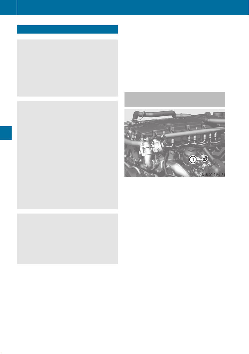
Important safety notes
60
Important safety notes
WARNING
G
If you do not have the prescribed service/
maintenance work or necessary repairs carried out, this could result in malfunctions or
system failures. There is a risk of an accident.
Always have the prescribed service/maintenance work as well as necessary repairs carried out at a qualified specialist workshop.
WARNING
G
There are moving components in the engine
compartment. Certain components may con-
Troubleshooting
tinue to move or suddenly move again even
after the ignition has been switched off, e.g.
the radiator fan. There is a risk of injury.
If you have to carry out work in the engine
compartment:
R
switch off the ignition
R
never touch the dangerous areas surrounding moving components, e.g. the rotation
area of the fan
R
remove jewellery and watches
R
keep items of clothing and hair, for example, away from moving parts.
WARNING
G
Certain engine components can become very
hot. There is a risk of injury when carrying out
work at the engine.
Where possible, allow the engine to cool down
and only touch the components described
below.
When working on the vehicle, comply with all
safety regulations, such as operating instructions, regulations concerning hazardous
materials, environmental protection measures, work safety and accident prevention
regulations.
Be aware of the road and traffic situation
when working on public roads and secure
your position accordingly.
Apart from careful operation and maintenance of the engine it is also important that
malfunctions be rectified in good time.
You can rectify certain malfunctions yourself
(Y page 36), (Y page 65).
Have malfunctions that you cannot eliminate
yourself rectified at a qualified specialist
workshop.
External engine start/engine stop button
You can start and switch off the engine using
the external engine start/engine stop button.
Before starting the engine
X
Switch the ignition lock to the drive position.
X
Shift into neutral.
X
Secure the vehicle against rolling away.
X
Deactivate power take-off.
Starting the engine
X
Press external engine start/engine stop
button : until the engine starts.
Starting the engine and increasing the
engine speed
X
Hold down external engine start/engine
stop button : until the desired engine
speed is achieved.
The engine starts and runs at engine idling
speed.
After about 3 seconds, the engine speed
increases. After releasing external engine
Page 63
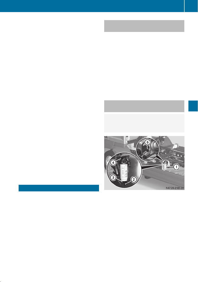
Bleeding and draining the fuel system
61
start/engine stop button :, the engine
continues to run at the currently set speed.
The engine speed can be increased up to
the limiting speed.
X
If the engine does not start immediately: interrupt the starting procedure
after no more than 30 seconds.
X
Turn the key in the ignition lock back to the
stop at key position g.
X
Repeat the starting procedure after a waiting period of approximately 1 minute.
X
If the engine fails to start: rectify the cause
of the poor starting characteristics
(Y page 65).
X
Observe the oil pressure gauge immediately after having started the engine.
Stopping the engine
X
Press external engine start/engine stop
button : again.
If you switch off the engine, the system
i
may continue to run for a short while.
Depending on the installation position,
operating state and ambient temperature,
circulation of AdBlue®/DEF is necessary
for ensuring cooling. To do this the
AdBlue®/DEF delivery pump is actuated
during this period.
Bleeding the fuel system without a fuel prefilter on the chassis frame
X
Turn the key to the start position in the
ignition lock and hold it. Do not depress the
accelerator pedal whilst doing so.
The starting procedure is automatically
i
cancelled after approximately 60 seconds.
X
Repeat the starting procedure after a waiting period of approximately 1 minute.
X
If the engine starts normally, depress the
accelerator pedal several times.
The fuel system is completely bled.
Bleeding the fuel system with a fuel prefilter on the chassis frame
Environmental note
H
Dispose of the water-fuel mixture in an environmentally responsible manner.
Troubleshooting
Bleeding and draining the fuel system
Bleeding, after refuelling a fuel system which
has been run dry, is performed the next time
the engine is started. Automatic continuous
bleeding takes place in the filter.
When the engine is started, the battery must
have sufficient charge to bleed the fuel system.
Example: fuel prefilter on the chassis frame
If water has collected in inspection window
=, drain fuel prefilter on chassis frame :
before bleeding. Drain fuel prefilter on chassis frame : regularly.
Draining the fuel prefilter on the chassis
frame
X
Place a collector under drain plug ;.
X
Turn drain plug ; open.
X
Operate hand pump ? and collect the
fuel/water mixture.
X
Turn drain plug ; closed.
Z
Page 64

Jump-starting
62
Bleeding using the hand pump of the fuel
prefilter on the chassis frame
X
Unscrew the fuel tank filler cap.
X
Place the collector underneath fuel prefilter :.
X
Unscrew bleed screw A.
X
Push hand pump ? repeatedly until the
fuel escaping at bleed screw A is free of
bubbles.
X
Tighten bleed screw A.
If there was no fuel in the fuel tank, press
i
hand pump ? again until there is noticeable resistance.
Troubleshooting
X
Tighten the fuel tank filler cap.
X
Turn the key to the start position in the
ignition lock and hold it. Do not depress the
accelerator pedal whilst doing so.
The starting procedure is automatically
i
cancelled after approximately 60 seconds.
X
Repeat the starting procedure after a waiting period of approximately 1 minute.
X
If the engine starts normally, depress the
accelerator pedal several times. The fuel
system is completely bled.
fuse rating are the same colour. Further information is available from any MTU or MTUauthorised Mercedes-Benz Service Centre
(Y page 10).
The fuse allocation chart is vehicle-specific
and is provided by the vehicle manufacturer.
If the newly inserted fuse also blows, have the
cause traced and rectified at a qualified specialist workshop, e.g. a Mercedes-Benz Service Centre.
X
If a circuit fails, switch off the consumer
equipment and switch the ignition lock to
position 0.
Checking and replacing a safety fuse
X
Pull the fuse out of the module using the
pliers and carry out a visual inspection.
X
If the fuse wire has melted, replace the
blown fuse with a spare fuse.
X
Switch on consumers and check that they
function correctly.
If the safety fuse burns out again, have the
electrical system checked at a qualified specialist workshop.
Electrical fuses
Important safety notes
WARNING
G
If you manipulate, bridge or replace a faulty
fuse with a fuse of a higher amperage, the
electric cables could be overloaded. This may
result in a fire. There is a risk of an accident
and injury.
Always replace faulty fuses with specified new
fuses of the correct amperage.
The individual electrical circuits are protected
by safety fuses or automatic circuit-breakers.
Blown fuses or defective automatic circuitbreakers must be replaced by equivalent
fuses with the fuse ratings recommended in
the fuse allocation chart. Fuses with the same
Jump-starting
Important safety notes
WARNING
G
Comply with safety precautions and take protective measures when handling batteries.
Risk of explosion
Fire, naked flames and
smoking are prohibited
when handling the battery.
Avoid creating sparks.
Battery acid is caustic.
Avoid contact with the skin,
eyes or clothing.
Page 65
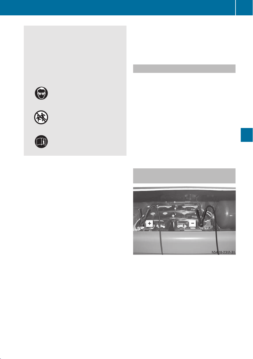
Wear suitable protective
clothing, in particular
gloves, an apron and a face
mask.
Immediately rinse acid
splashes off with clean
water. Consult a doctor if
necessary.
Wear eye protection.
Keep children away.
Observe this Owner's Manual.
Observe the following notes. You could
!
otherwise damage the battery or electronic
components in the vehicle:
R
do not use a battery quick-charge unit for
jump-starting.
R
if you use a mobile battery charger (battery device with mains power stage),
remove the mains plug before jumpstarting.
R
only have jump-starting provided by vehicles with a 24 V system.
R
use jump leads which are protected
against polarity reversal and with a wire
cross section of approximately 35–
50 mm2 and insulated terminal clamps.
R
if the outside temperature drops below
Ò10 †, a discharged battery could freeze.
Do not start the engine under these circumstances. Let the battery thaw out
first.
Do not connect the negative terminal
!
clamp of the jump lead to the chassis
frame. Otherwise, engine or transmission
components can be damaged.
Jump-starting
When you remove the jump leads, let the
!
engine of the vehicle being jump-started
idle. This avoids damage being caused to
the vehicle electronics.
General notes
Observe the instructions relevant to safety
and protective measures when handling the
battery.
After jump-starting, have the batteries
checked at a qualified specialist workshop.
X
Make sure that the vehicles are not touching.
X
Engage the parking brake.
X
Switch off all electrical consumers.
X
Turn the key to position 0 in the ignition
lock.
Vehicles without a jump-starting connection point
Connecting the jump lead
X
Remove the battery compartment cover.
X
First, connect the positive terminal clamp
of the jump lead to the positive terminal of
the other vehicle's battery and then to the
q positive terminal of the starter battery.
X
First, connect the negative terminal clamp
of the jump lead to the negative terminal of
the other vehicle's battery and then to the
± negative terminal of the starter battery.
63
Troubleshooting
Z
Page 66

Jump-starting
64
X
Assisting vehicle: run the engine at a high
speed.
X
Start the engine and allow it to idle.
Disconnecting the jump lead
X
First, disconnect the negative terminal
clamps of the jump lead from the negative
terminals.
X
Remove the positive terminal clamps of the
jump lead from the positive terminals.
Troubleshooting
Page 67

Troubleshooting
Troubleshooting
Engine problems
WARNING
G
If you do not have the prescribed service/maintenance work or necessary repairs carried out, this
could result in malfunctions or system failures. There is a risk of an accident.
Always have the prescribed service/maintenance work as well as necessary repairs carried out
at a qualified specialist workshop.
Apart from careful operation and maintenance of the engine it is also important that malfunctions be rectified in good time. You can rectify certain faults yourself.
Have malfunctions that you cannot eliminate yourself rectified at a qualified specialist workshop (Y page 10).
Problem
Possible causes/consequences and M Solutions
65
Troubleshooting
The drive pinion does
not turn or turns too
slowly.
The engine does not
start or stalls again
immediately.
The battery is not sufficiently charged.
X
Charge the battery.
The connecting cable to the starter motor is loose.
X
Tighten the cable on the terminal. If necessary, solder on a new
terminal.
The earth connection to the battery is loose.
X
Tighten the cable on the terminal. If necessary, solder on a new
terminal.
The starter motor solenoid switch is faulty or the starter motor is
faulty.
X
Have it checked at a qualified specialist workshop.
The fuel tank is empty.
X
Refill the fuel tank (Y page 43).
The fuel filter is blocked.
X
Replace the filter element.
The fuel prefilter contains water.
X
Drain the fuel prefilter.
The fuel prefilter is blocked.
X
Replace the filter element.
Z
Page 68

Troubleshooting
66
Problem
Engine fails to start
when the ambient temperature is low.
Troubleshooting
The engine stops inadvertently.
Possible causes/consequences and M Solutions
Leaks or insufficient pressure in the low-pressure fuel circuit
X
Check for leaks (visual check), replace the seals if necessary.
X
Have the fuel pressure tested at a qualified specialist workshop.
Replace the seals.
The fuel is not resistant to cold.
The flow properties of the diesel fuel are inadequate due to paraffin
separation.
X
Malfunctions resulting from paraffin separation can be corrected by warming the entire fuel system, e.g. by parking the vehicle
in a heated area.
X
Refuel with winter fuel (Y page 52).
The engine oil viscosity is incorrect.
X
Alter the engine oil viscosity to the conditions of use
(Y page 50).
X
If the engine does not start after another attempt, have the
cause traced and rectified at a qualified specialist workshop.
The power supply to the engine management (MCM) or the
exhaust gas aftertreatment (ACM) control modules is interrupted
or there is a short circuit in the wiring.
X
Check the electrical fuses
X
Have the power supply checked at a qualified specialist workshop.
The engine is in emergency running mode.
The engine surges,
vibrates or runs irregularly.
The engine's output is
poor (lack of power).
Leaks or insufficient pressure in the low-pressure fuel circuit.
X
Carry out a check for leaks (visual check).
X
Have the fuel pressure tested at a qualified specialist workshop.
There is an interruption to the control units' data flow.
X
Check the connectors on the control units for secure seating
and corrosion.
X
Read out the control unit's fault memory.
X
Have it checked at a qualified specialist workshop.
There is a malfunction in the fuel system.
X
Carry out a check for leaks (visual check).
X
Read out the control unit's fault memory.
X
Have it checked at a qualified specialist workshop.
The air filter is dirty or blocked.
X
Replace the air filter element.
Page 69

Troubleshooting
67
Problem
Possible causes/consequences and M Solutions
The charge-air temperature is too high; the charge-air cooler or
radiator is dirty on the exterior.
X
Clean the exterior of the charge-air cooler and radiator.
The coolant temperature is too high.
X
Check the temperature sensor; replace if necessary. Check the
fan speed.
X
Check the thermostat and replace as necessary. Consult a
qualified specialist workshop.
Malfunction in the fuel system (blocked, leaking).
X
Visual inspection for leaks
X
Consult a qualified specialist workshop.
Poor fuel grade
X
Use the specified type of fuel and fuel grade (Y page 52).
The charge-air system is leaking; the hose clip on the charge-air
hose is loose or damaged.
X
Check the charge-air system for leaks.
X
Check the charge-air pressure sensor and, if necessary, replace.
X
Consult a qualified specialist workshop.
An operating restriction is activated due to an emissions-relevant
malfunction.
X
Observe information on the warning and indicator lamps
(Y page 20).
Troubleshooting
There is an interruption
in the tractive power.
The engine braking
effect is poor.
Fuel consumption is
too high.
The engine gets too hot
(according to the coolant temperature
gauge).
There is an increased voltage drop to the control units (loose contact).
X
Check the battery terminals on the battery and the connectors
on the control units for secure seating and corrosion.
The cause must be established in a qualified specialist workshop.
X
Consult a qualified specialist workshop.
The cause must be established in a qualified specialist workshop.
X
Consult a qualified specialist workshop.
There is not enough coolant in the cooling system.
X
Add and bleed the coolant.
The coolant temperature sensor or display is faulty.
X
Replace the sensor or display.
Z
Page 70

Troubleshooting
68
Problem
Troubleshooting
Indicator lamps do not
light up at IGNITION
ON.
The charge current indicator lamp lights up
when the engine is running.
Possible causes/consequences and M Solutions
The poly-V-belt is damaged.
X
Replace the poly-V-belt.
The fan does not switch on correctly.
X
Consult a qualified specialist workshop.
The radiator is dirty on the inside; the radiator is very dirty on the
outside.
X
Clean the radiator.
The thermostat is faulty.
X
Check and replace as necessary.
X
Consult a qualified specialist workshop.
The lamps are faulty or the electrical cables are interrupted.
X
Consult a qualified specialist workshop.
The poly-V-belt is slipping.
X
Check the belt tensioner function.
X
Check that the poly-V-belt contact surfaces are not torn, damaged, oily or glazed. Replace the poly-V-belt if necessary.
The poly-V-belt is torn.
X
Replace the poly-V-belt.
The engine is "knocking".
The engine is "knocking".
There are abnormal
sounds.
The alternator or sensor is faulty.
X
Check the alternator or sensor.
X
Consult a qualified specialist workshop.
The engine is misfiring.
X
Consult a qualified specialist workshop.
There is bearing damage.
X
Consult a qualified specialist workshop.
The air intake pipe and exhaust gas pipe are leaking, causing a
whistling noise.
X
Rectify the cause of the leak and, if necessary, replace gaskets.
Page 71

Troubleshooting
69
Problem
Possible causes/consequences and M Solutions
The turbine or compressor wheel is scraping the housing; there are
foreign objects in the compressor or turbine housing; bearings
have seized on the rotating parts.
X
Have the exhaust gas turbocharger checked at a qualified specialist workshop.
The valve clearance is excessive.
X
Check and adjust the valve clearance.
The poly-V-belt is slipping.
X
Check that the poly-V-belt contact surfaces are not torn, damaged, oily or glazed. Replace the poly-V-belt if necessary.
Troubleshooting
Z
Page 72

70
Page 73

Identification plates ............................ 72
Data card ............................................. 72
Engine data .......................................... 72
71
Technical data
Page 74
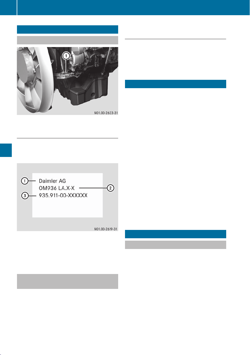
Engine data
72
Identification plates
Engine data plate
:
Position of engine data plate (example)
Information on the engine data plate
Technical data
The following data is contained on the engine
data plate in the form of numbers stamped
directly onto the crankcase:
Information on the exhaust gas aftertreatment identification plate
The identification plate for the exhaust gas
aftertreatment unit contains the 14-digit
identification number (AGN ID number) of the
exhaust gas aftertreatment unit.
Data card
The data card forms an integral part of the
documents belonging to the engine and
should always be kept with the Maintenance
Booklet. It contains details about the design
of the engine and the exhaust gas aftertreatment system, including special features.
Conversion parts on the engine system which
change the scope of the engine delivered by
Mercedes-Benz should be reported to
Mercedes-Benz. Once the documentation
(VeDoc) has been updated, an updated data
card is supplied. This helps to prevent incorrect ordering of replacement parts.
The following is absolutely necessary when
procuring genuine Mercedes-Benz parts:
R
the data card or
R
the complete engine number and the number of the exhaust gas aftertreatment unit.
Example: engine data plate
:
Manufacturer's name
;
Engine model designation
=
Engine number
Exhaust gas aftertreatment identification plate
The exhaust gas aftertreatment identification
plate is located on the exhaust gas aftertreatment control module (ACM).
Engine data
Dimensions and weights
All data refers to the standard version of the
respective engine type. Deviations may
occur, depending on the engine equipment
and installation situation in the vehicle/
equipment.
Page 75
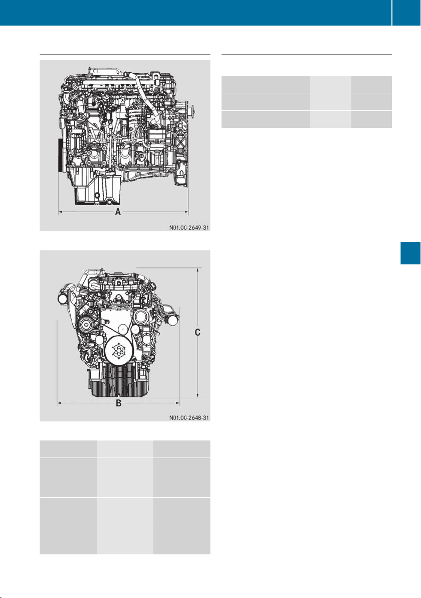
Engine data
73
Dimensions
Example: engine length
Weights
Engine weight DIN 70020 - GZ
1
4R 1000 6R 1000
Single stage charging - -
Two stage charging - -
Technical data
Example: engine width and height
R4 1000 R6 1000
A = engine
917 mm 1070 mm
length with
fan
B = engine
840 mm 1050 mm
width
C = engine
1025 mm 1050 mm
height
1
Data not available at the time of going to print.
Page 76

Engine data
74
General data
All data refers to the standard version of the respective engine type. Data for other versions is
available on request.
Engine Engine type 4R 1000 6R 1000
Assembly model series 933.91 935.91
Type In-line engine with exhaust gas recirculation and
charge-air pressure control
Combustion principle 4-stroke direct injection diesel
Number of cylinders 4 6
Bore 110 mm 110 mm
Stroke 135 mm 135 mm
Technical data
Engine capacity
Firing order 1 -3 -4 -2 1 - 5 - 3 - 6 - 2 - 4
Type of cooling system Forced circulation cooling
5130 cm
3
7700 cm
3
Engine, direction of
rotation
Valve clearance
Starter
motor
Alternator Voltage 24 V 24 V
Intake valve 0.30 mm +/- 0.05 mm 0.30 mm +/- 0.05 mm
Exhaust valve 0.60 mm +/- 0.1 mm 0.60 mm +/- 0.1 mm
Engine brake when
adjusting gauges
(0.6 mm) are used on
the exhaust valve
Starter Electric Electric
Voltage 24 V 24 V
Output 3.9 kW 5.5 kW
Cold-start limit Ò30 † (battery charging level 75%)
Amperage 100 A 150 A
Anti-clockwise (when looking at the flywheel)
0.15 mm 0.15 mm
Operating data
Operating range of engine brake Approx. 1000 - 3000 rpm
Engine speed range of maximum engine torque Approx. 1200 - 1600 rpm
Page 77

Engine data
Engine speed of maximum power output Approx. 2200 rpm
4R 1000 idling speed Approx. 680 rpm
6R 1000 idling speed Approx. 600 rpm
Oil pressure at idling speed Minimum 0.5 bar
75
Coolant temperature
Normal operation Approx. 85 - 100 †
Maximum permissible temperature of coolant (automatic torque limitation up to
50 % from 103 †)
Capacities and service products
Engine with
oil filter
(with stand-
4R 1000 Approx. 20.5 l Engine oil (Sheet
6R 1000 Approx. 27.0 l
ard truck oil
pan)
Fuel system
Exhaust gas
Diesel fuel tank
AdBlue®/DEF tank AdBlue®/DEF in
3
aftertreatment system
Capacity approx-
imately
105 †
Service product
(Sheet No.2)
228.51, 228.31, 228.5
or 228.3)
Diesel fuels in accordance with EN 590 or
ASTM D975 (Sheet
131.0)
accordance with ISO
22241 (Sheet No.
352.1)
Technical data
AdBlue®/DEF filter sealing
rings
Cooling system
Amount of coolant in the engine
4R 1000
6R 1000
Corrosion inhibitor/antifreeze agent volume
down to –37 °C
2
Mercedes-Benz Specifications for Service Products
3
Fitted on the vehicle. Designed by vehicle manufacturer.
- MB silicon grease
Approx. 21 l
Approx. 23.5 l
Antifreeze/corrosion
inhibitor in accordance
with Sheet 325.5 or pre-
Approx. 50% by
volume
mixed coolant in
accordance with Sheet
326.5. Water quality in
accordance with Sheet
310.1
Page 78

Engine data
76
Engine compartment
Capacity approx-
imately
Corrosion inhibitor/antifreeze volume
down to –45 °C
Protective wax - Wax preservative in
Max. 55% by vol-
ume
Service product
(Sheet No.2)
accordance with Sheet
385.4
Tightening torques
All threads on mechanical components and the corresponding contact surfaces must be clean,
smooth and coated with engine oil. Other lubricants lead to substantially different tightening
torques.
The tightening torques are the same for 4R 1000 and 6R 1000.
Technical data
Engine Cylinder head cover screw on
the rocker arm housing
(observe the tightening
sequence for the cylinder
head cover)
Valve clearance setting Counternut on the rocker
Screw of TDC inspection hole cap on the flywheel housing 30 Nm
Light alloy 20 Nm
Plastic 25 Nm
50 Nm
arm adjustment screw
Cranking device screw on the timing case 25 Nm
Fuel system Main fuel filter cap on the fuel filter module 25 Nm
Fuel prefilter cap on the fuel filter module 15 Nm
Oil circuit Drain plug on the oil pan
(plastic)
Oil filter cap on the oil/coolant module 50 Nm
Cooling system Silicate gel cartridge on the coolant pump 50 Nm
Exhaust gas
aftertreatment
Air dryer Granulate cartridge on the air dryer 15 Nm
2
Mercedes-Benz Specifications for Service Products
Filter housing on the pump module 80 Nm
M 16 x 1.5 35 Nm
Page 79
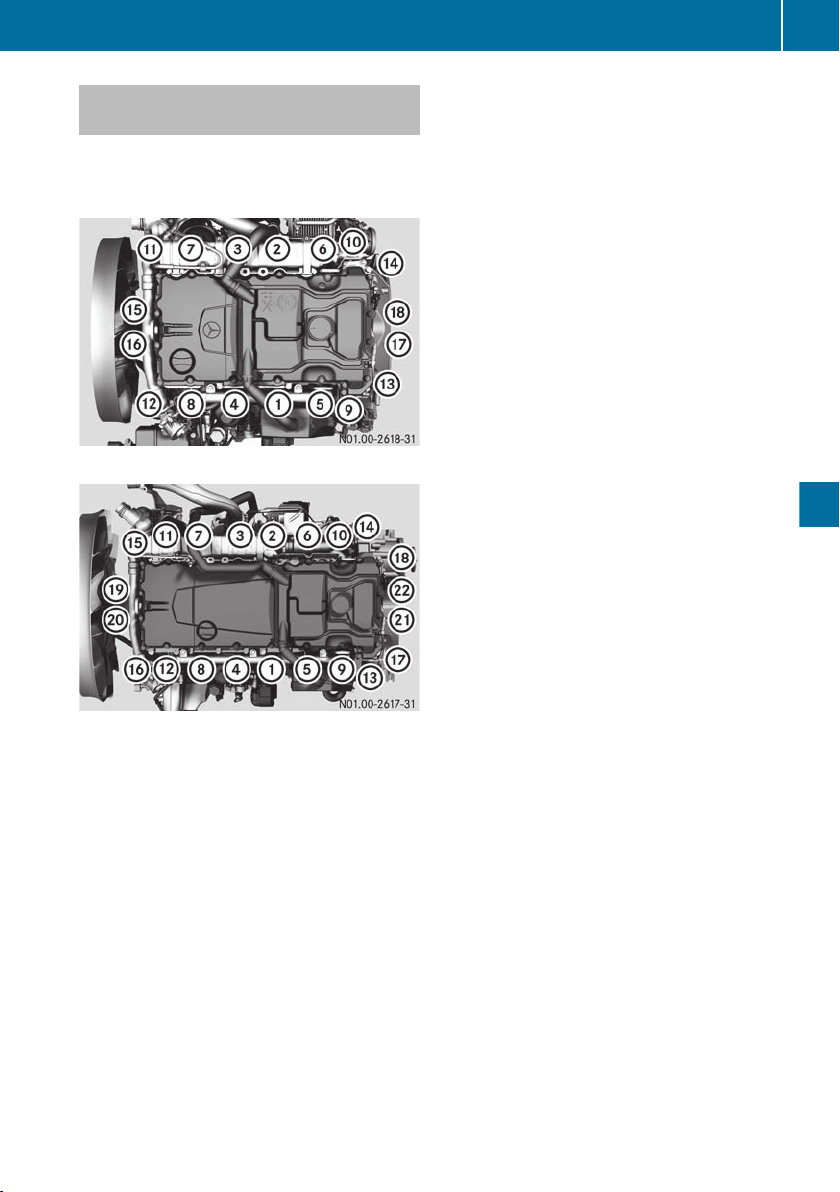
Tightening sequence for the cylinder head cover
The cylinder head cover screws must be tightened in the correct tightening sequence in the
same order as described below.
Engine data
77
Tightening sequence for 4R 1000
Tightening sequence for 6R 1000
Technical data
Page 80

787980
Page 81

Page 82

Page 83

Imprint
Internet
Further information about MTU, MercedesBenz and Daimler AG can be found on the
Internet at:
www.mtu-online.com
www.mercedes-benz.com
www.daimler.com
Documentation team
Should you have any questions or suggestions regarding this manual, you can reach
the technical documentation team at the following address:
Daimler AG, HPC: CAC, Customer Service,
70546 Stuttgart, Germany
©
Daimler AG: not to be reprinted, translated
or otherwise reproduced, in whole or in part,
without written permission from Daimler AG.
Equipment manufacturer
Daimler AG
Mercedesstraße 137
70327 Stuttgart
Germany
As at 21.10.2013
Page 84

É9345843771)ËÍ
9345843771
Order no. 6462 9839 02 Part no. 934 584 37 71 Edition 01-14
 Loading...