

Page 1

USER MANUAL
61301603708 Rev. A
®
SERIES 2200
TUNNEL, CAGE, AND
UTENSIL WASHERS
Page 2

Page 3

USER MANUAL
®
SERIES 2200
TUNNEL, CAGE, AND
UTENSIL WASHER
Getinge/Castle, Inc.
1777 East Henrietta Road
Rochester, New York 14623-3133
Phone: (800) 950-9912 USA
Facsimile: (800) 950-2570
Page 4
WARNING
CAUTION
USER MANUAL 61301603708
Rev. A New Release(08/31/2000)
Related Publications:
Service Data Manual 61301603707
Customer Manual—keyed to the customer’s specific serial number
DESCRIPTION OF SYMBOLS & NOTES IN MANUAL
The following symbols with related notes appear in this manual.
“Warning” notes alert the user to the possibility of personal injury.
“Caution” notes alert the user to the possibility of damage to the equipment.
NOTE
NOTE
“Notes” alert the user to pertinent facts and conditions.
This manual contains proprietary information of Getinge/Castle, Inc. It shall
not be reproduced in whole or in part without the written permission of
Getinge/Castle, Inc.
Castle
®
and are registered trademarks of Getinge/Castle, Inc.
®
Copyright ©2000 by Getinge/Castle, Inc.
Page 5

SPECIAL SAFETY INSTRUCTIONS . . . . . . . . . . . . . . . . . . vii
Section 1 General Description
INTRODUCTION . . . . . . . . . . . . . . . . . . . . . . . . . . . . . . . . 1–1
EXTERNAL COMPONENTS . . . . . . . . . . . . . . . . . . . . . . . 1–4
INTERNAL COMPONENTS. . . . . . . . . . . . . . . . . . . . . . . . 1–7
MOST COMMON OPTIONS . . . . . . . . . . . . . . . . . . . . . . . 1–9
Table of Contents
Standard Features . . . . . . . . . . . . . . . . . . . . . . . . . . . . 1–2
Optional Features . . . . . . . . . . . . . . . . . . . . . . . . . . . . 1–3
Control Panel . . . . . . . . . . . . . . . . . . . . . . . . . . . . . . . . 1–4
Emergency Stop Cable . . . . . . . . . . . . . . . . . . . . . . . . 1–4
Alarm (not shown) . . . . . . . . . . . . . . . . . . . . . . . . . . . . 1–4
Wash Chamber Access Doors. . . . . . . . . . . . . . . . . . . 1–5
Rinse Chamber Access Door. . . . . . . . . . . . . . . . . . . . 1–5
Final Rinse Heat Exchanger . . . . . . . . . . . . . . . . . . . . 1–5
Drawer and Basket-Type Debris Filters. . . . . . . . . . . . 1–5
Agent Injection Ports (not shown) . . . . . . . . . . . . . . . . 1–5
Exhaust Plenum (not shown). . . . . . . . . . . . . . . . . . . . 1–5
Six-Foot Recirculated Air Dryer (not shown) . . . . . . . . 1–5
Seven-Foot 99% Plastic Cage Dryer . . . . . . . . . . . . . . 1–5
Ten-Foot Recirculated Air Dryer (not shown) . . . . . . . 1–5
Unload Roller Conveyor. . . . . . . . . . . . . . . . . . . . . . . . 1–6
Control Box Access Panel . . . . . . . . . . . . . . . . . . . . . . 1–6
Electrical Disconnect Switch . . . . . . . . . . . . . . . . . . . . 1–6
Upper Spray Manifold . . . . . . . . . . . . . . . . . . . . . . . . . 1–7
Lower Spray Manifold . . . . . . . . . . . . . . . . . . . . . . . . . 1–7
Hydraulic Hold Down (not shown) . . . . . . . . . . . . . . . . 1–8
Wash, Rinse, and Final Rinse Treatment Temperature
Guarantees (not shown) . . . . . . . . . . . . . . . . . . . . 1–8
Water Conservation (not shown) . . . . . . . . . . . . . . . . . 1–8
Stainless Steel Treatment Components . . . . . . . . . . . 1–9
House Tap Water Temperature Booster . . . . . . . . . . . 1–9
Steam and Water Pressure Gauges . . . . . . . . . . . . . . 1–9
Automatic Self Cleaning Debris Filter . . . . . . . . . . . . . 1–9
Automatic Drain System . . . . . . . . . . . . . . . . . . . . . . . 1–9
Drain Discharge Cool Down Injection System . . . . . . . 1–9
Washer Interior Cleaning and Descaling System . . . . 1–9
Automatic Conveyor Stop . . . . . . . . . . . . . . . . . . . . . . 1–9
Recorder/Printer. . . . . . . . . . . . . . . . . . . . . . . . . . . . . . 1–9
61301603708 iii
Page 6

Section 2 The Control Panel
GENERAL MACHINE DESCRIPTION. . . . . . . . . . . . . . . 1–10
Automatic Treatment Cycle . . . . . . . . . . . . . . . . . . . . 1–10
Treatment Schedule . . . . . . . . . . . . . . . . . . . . . . . . . 1–10
Temperature Guarantee System. . . . . . . . . . . . . . . . 1–11
INTRODUCTION . . . . . . . . . . . . . . . . . . . . . . . . . . . . . . . . 2–1
TOUCH CONTROL PANEL (TCP) . . . . . . . . . . . . . . . . . . 2–2
Control Screens. . . . . . . . . . . . . . . . . . . . . . . . . . . . . . 2–2
Cycle Programming. . . . . . . . . . . . . . . . . . . . . . . . . . . 2–8
Example: Programming a Sample Cycle. . . . . . . . . . . 2–8
LED CONTROLLER . . . . . . . . . . . . . . . . . . . . . . . . . . . . 2–12
Key Locations . . . . . . . . . . . . . . . . . . . . . . . . . . . . . . 2–12
Data Entry Keys (keypad) . . . . . . . . . . . . . . . . . . . . . 2–15
Control Sequences . . . . . . . . . . . . . . . . . . . . . . . . . . 2–16
Processing Cycle Screen Description . . . . . . . . . . . . 2–18
Standby Screen. . . . . . . . . . . . . . . . . . . . . . . . . . . . . 2–18
SELECT CYCLE . . . . . . . . . . . . . . . . . . . . . . . . . . . . 2–18
REVIEW CYCLE . . . . . . . . . . . . . . . . . . . . . . . . . . . . 2–19
MANUAL MODE . . . . . . . . . . . . . . . . . . . . . . . . . . . . 2–20
Cycle Programming. . . . . . . . . . . . . . . . . . . . . . . . . . 2–21
Cycle Selection . . . . . . . . . . . . . . . . . . . . . . . . . . . . . 2–22
Programming a Cycle . . . . . . . . . . . . . . . . . . . . . . . . 2–22
Example: Programming a Sample Cycle. . . . . . . . . . 2–24
Start Up . . . . . . . . . . . . . . . . . . . . . . . . . . . . . . . . . . . 2–24
Programming. . . . . . . . . . . . . . . . . . . . . . . . . . . . . . . 2–24
Starting Wash Cycle . . . . . . . . . . . . . . . . . . . . . . . . . 2–26
Alarm . . . . . . . . . . . . . . . . . . . . . . . . . . . . . . . . . . . . . 2–26
Help . . . . . . . . . . . . . . . . . . . . . . . . . . . . . . . . . . . . . . 2–26
ELECTRO-MECHANICAL CONTROLS . . . . . . . . . . . . . 2–27
Control Panel. . . . . . . . . . . . . . . . . . . . . . . . . . . . . . . 2–27
Cycle Programming. . . . . . . . . . . . . . . . . . . . . . . . . . 2–30
Final Rinse Temperature Settings. . . . . . . . . . . . . . . 2–30
Internal Timers. . . . . . . . . . . . . . . . . . . . . . . . . . . . . . 2–31
Section 3 Operating Instructions
GENERAL MACHINE OPERATION . . . . . . . . . . . . . . . . . 3–1
Start-up . . . . . . . . . . . . . . . . . . . . . . . . . . . . . . . . . . . . 3–1
Operating Instructions . . . . . . . . . . . . . . . . . . . . . . . . . 3–1
Shutdown. . . . . . . . . . . . . . . . . . . . . . . . . . . . . . . . . . . 3–2
Treatment Schedule . . . . . . . . . . . . . . . . . . . . . . . . . . 3–2
DAILY CHECKLIST . . . . . . . . . . . . . . . . . . . . . . . . . . . . . . 3–3
Operational Readiness . . . . . . . . . . . . . . . . . . . . . . . . 3–3
iv
Page 7

Section 4 Maintenance
Section 5 Troubleshooting
EMERGENCY STOP . . . . . . . . . . . . . . . . . . . . . . . . . . . . . 3–4
Using the Emergency Cable . . . . . . . . . . . . . . . . . . . . 3–4
EMERGENCY SHUT-DOWN. . . . . . . . . . . . . . . . . . . . . . . 3–4
Shutting Down the Washer . . . . . . . . . . . . . . . . . . . . . 3–4
GENERAL MAINTENANCE SCHEDULE. . . . . . . . . . . . . . 4–1
ROUTINE MAINTENANCE SCHEDULE—STANDARD . . 4–2
When required . . . . . . . . . . . . . . . . . . . . . . . . . . . . . . . 4–2
Daily. . . . . . . . . . . . . . . . . . . . . . . . . . . . . . . . . . . . . . . 4–2
Weekly . . . . . . . . . . . . . . . . . . . . . . . . . . . . . . . . . . . . . 4–4
Monthly . . . . . . . . . . . . . . . . . . . . . . . . . . . . . . . . . . . . 4–4
Six Months . . . . . . . . . . . . . . . . . . . . . . . . . . . . . . . . . . 4–5
RECOMMENDED SPARE PARTS LIST . . . . . . . . . . . . . . 4–6
Consumable Stock. . . . . . . . . . . . . . . . . . . . . . . . . . . . 4–6
Spare Parts . . . . . . . . . . . . . . . . . . . . . . . . . . . . . . . . . 4–6
CYLE INTERRUPT CONDITIONS. . . . . . . . . . . . . . . . . . . 5–3
Resettable . . . . . . . . . . . . . . . . . . . . . . . . . . . . . . . . . . 5–3
Non-Resettable . . . . . . . . . . . . . . . . . . . . . . . . . . . . . . 5–3
Section 6 Installation Instructions
INTRODUCTION . . . . . . . . . . . . . . . . . . . . . . . . . . . . . . . . 6–1
UNCRATING & EQUIPMENT INSPECTION . . . . . . . . . . . 6–1
INSTALLATION /ASSEMBLY CHECKLIST . . . . . . . . . . . . 6–2
Equipment Location . . . . . . . . . . . . . . . . . . . . . . . . . . . 6–2
Utilities . . . . . . . . . . . . . . . . . . . . . . . . . . . . . . . . . . . . . 6–2
Electrical . . . . . . . . . . . . . . . . . . . . . . . . . . . . . . . . . . . 6–2
STARTUP. . . . . . . . . . . . . . . . . . . . . . . . . . . . . . . . . . . . . . 6–3
Touch Control Panel (TCP) . . . . . . . . . . . . . . . . . . . . . 6–3
LED Control Panel . . . . . . . . . . . . . . . . . . . . . . . . . . . . 6–4
Electro-Mechanical Controls . . . . . . . . . . . . . . . . . . . . 6–5
CHECK-OUT PROCEDURE . . . . . . . . . . . . . . . . . . . . . . . 6–6
TECHNICAL DATA. . . . . . . . . . . . . . . . . . . . . . . . . . . . . . . 6–6
Section 7 Options
INTRODUCTION . . . . . . . . . . . . . . . . . . . . . . . . . . . . . . . . 7–1
MOST COMMON OPTIONS . . . . . . . . . . . . . . . . . . . . . . . 7–1
Right or Left Handed Service. . . . . . . . . . . . . . . . . . . . 7–1
Wash and Rinse Treatment Temperature Guarantee . 7–1
61301603708 v
Page 8

Final Rinse Temperature Guarantee. . . . . . . . . . . . . . 7–1
Controls . . . . . . . . . . . . . . . . . . . . . . . . . . . . . . . . . . . . 7–2
RS232 Data Computer Port. . . . . . . . . . . . . . . . . . . . . 7–3
RS485 Data Computer Port. . . . . . . . . . . . . . . . . . . . . 7–3
Bedding Dispenser Controls . . . . . . . . . . . . . . . . . . . . 7–3
Bedding Dump Station Controls . . . . . . . . . . . . . . . . . 7–3
Printer . . . . . . . . . . . . . . . . . . . . . . . . . . . . . . . . . . . . . 7–3
Stainless Steel Treatment Components . . . . . . . . . . . 7–7
Automatic Self Cleaning Debris Filter . . . . . . . . . . . . . 7–8
Automatic Drain System . . . . . . . . . . . . . . . . . . . . . . . 7–8
Wash Interior Cleaning and Descaling System . . . . . . 7–9
Acid Treatment System . . . . . . . . . . . . . . . . . . . . . . . . 7–9
Non-Recirculated Final Pure Water Rinse. . . . . . . . . 7–10
Water Pressure Reducing Station . . . . . . . . . . . . . . . 7–10
House Tap Water Temperature Booster . . . . . . . . . . 7–10
Automatic Agent Injection System (Optional) . . . . . . 7–10
Automatic Agent Injection System – Time Based . . . 7–12
Agent Neutralization System Non-Monitored . . . . . . 7–12
pH Monitored. . . . . . . . . . . . . . . . . . . . . . . . . . . . . . . 7–13
Mechanical Hold Down System. . . . . . . . . . . . . . . . . 7–13
Six Foot Recirculated Air Dryer Section . . . . . . . . . . 7–14
Seven Foot 99% Plastic Cage Dryer . . . . . . . . . . . . . 7–14
Ten Foot Recirculated Air Dryer Section. . . . . . . . . . 7–15
Load/Unload Conveyor . . . . . . . . . . . . . . . . . . . . . . . 7–15
Power Discharge Unload Conveyor . . . . . . . . . . . . . 7–15
Automatic Conveyor Stop . . . . . . . . . . . . . . . . . . . . . 7–15
Exhaust Plenum System . . . . . . . . . . . . . . . . . . . . . . 7–16
Power Exhaust . . . . . . . . . . . . . . . . . . . . . . . . . . . . . 7–16
Drain Discharge Cool-Down Injection System –
Non-Monitored . . . . . . . . . . . . . . . . . . . . . . . . . . 7–17
Steam and Water Pressure Gauges . . . . . . . . . . . . . 7–17
Chilled Water Vapor Removal Condenser. . . . . . . . . 7–17
Barrier Trim Flange System. . . . . . . . . . . . . . . . . . . . 7–17
M.O.D.E.M. (MTP Online Diagnostics, Evaluation,
and Monitoring) System . . . . . . . . . . . . . . . . . . . 7–18
Seismic . . . . . . . . . . . . . . . . . . . . . . . . . . . . . . . . . . . 7–18
Appendix A Manual Screens
Index
vi
INTRODUCTION . . . . . . . . . . . . . . . . . . . . . . . . . . . . . . . . A–1
PROGRAMMING A CYCLE USING MANUAL MODE. . . . A–1
Page 9

SPECIAL SAFETY INSTRUCTIONS
THE FOLLOWING SAFETY INSTRUCTIONS APPEAR WITHIN THIS
MANUAL. READ THEM CAREFULLY BEFORE OPERATING THE UNIT.
WARNING
“Warning” notes alert the user to the possibility of personal
injury.
Warnings Summary p. xi
BURN HAZARD:This washer operates at extremely high temperatures.
Prior to any machine maintenance or service, the washer should be allowed
sufficient time to cool. Caution should be used in and around the washer
chamber and external piping. Water flow and discharge piping can cause
personal injury such as burns. Operators should partially open the chamber
door to allow hot air to exhaust and to allow all loads adequate time to cool.
Opening the chamber door fully may cause large amounts of steam to
escape.
SHOCK HAZARD: Prior to any service or maintenance on the washer, all
utilities should be disconnected and the lockout/tagout procedures should
be followed to insure safety and prevent accidental shock.
PERSONAL HAZARD AND EQUIPMENT DAMAGE: Safe and efficient
operation of this equipment requires scheduled preventative maintenance.
Routine adjustments and replacement of parts by other than qualified
maintenance personnel may cause personal injury or the equipment to
perform less than its capabilities.
General Machine Operation p. 3-1
BURN HAZARD: Do not open station access doors during a cycle.
This could release hot water through the door opening, resulting in
burns to personnel.
Daily Checklist p. 3-3
HOT SURFACES: The area surrounding the load and unload end of the
washer could be hot. Use caution when loading or unloading ware.
Routine Operation: Detail p. 3-6
BURN HAZARD: Do not open a Washer door during a cycle. This could
release hot water through the door opening, resulting in burns to personnel.
Routine Maintenance Schedule - Standard, Every Six Months p 4-4
ELECTRIC SHOCK HAZARD: Only an electrician should perform this test!
61301603708 vii
Page 10

viii
Page 11
INTRODUCTION
Section 1 General Description
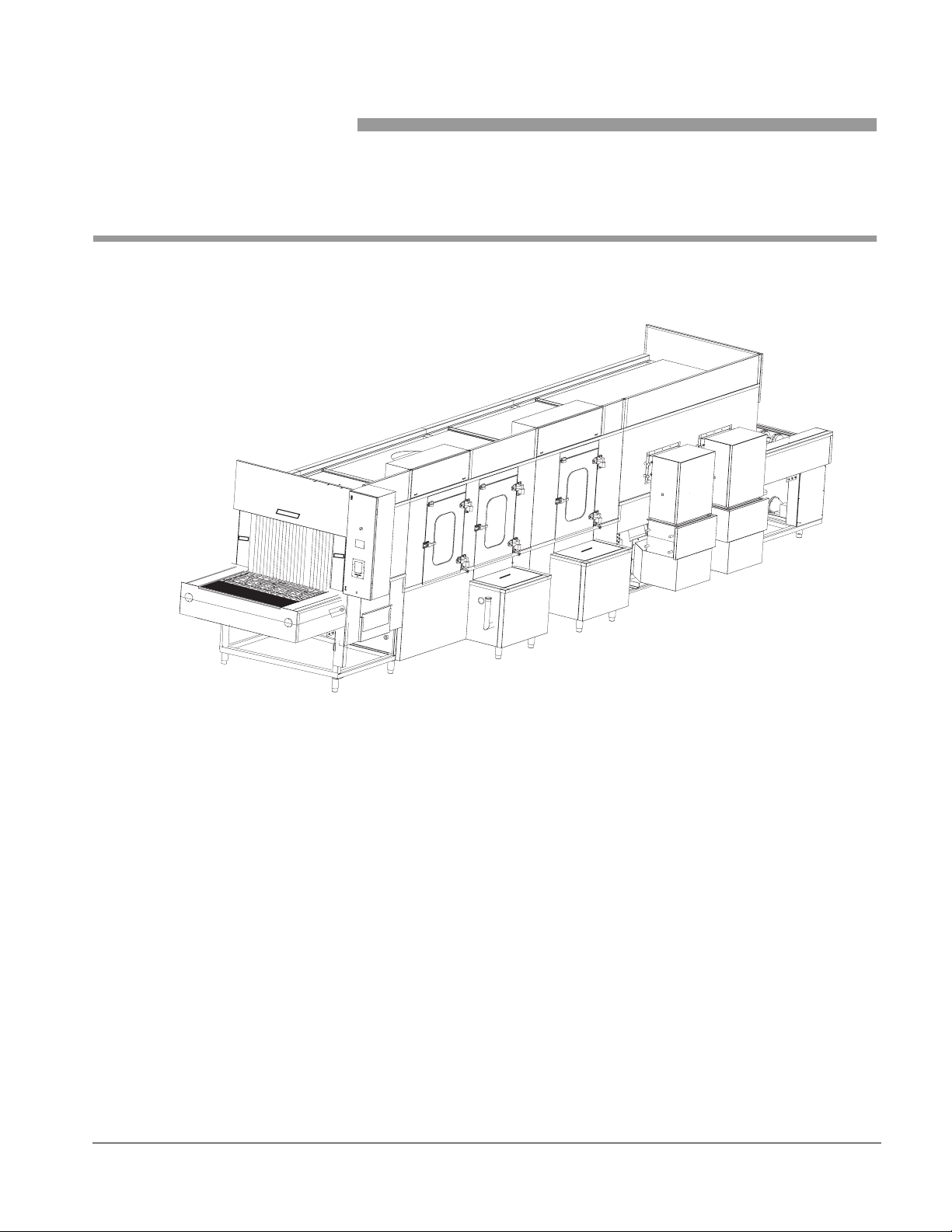
Figure 1–1. MTP 2200 SERIES WASHERS
MTP
2200 series units are automatic, heavy duty, tunnel-type hydrospray
washers with conveyors. They are designed for continuous high volume
processing. These units are designed to clean, sanitize, and dry— efficiently
and thoroughly —metal or plastic cages, racked watering bottles, and
utensils used in research animal care facilities.
Units may be recessed through one or two walls or installed free standing.
Left side service access and control terminal location is standard with right
side service access and control terminal location optional.
61301603708 1–1
Page 12

General Description
Models and dimensions are listed in Table 1–1.
Table 1–1. MTP 2200 series washers
MODEL CHAMBER
2224 25x25
[64x64]
2230 31x25
[79x64]
2236 37x25
[94x64]
2242 43x25
[107x64]
2248 48x25
[122x64]
(in. [cm])
OVERALL
(in. [cm])
65½x85
[145x213]
71½x85
[160x213]
77½x85
[175x213]
83½x85
[212x213]
89½x85
[227x213]
Routine operation consists of manually placing the items to be cleaned
upside down on the conveyor belt at the load end of the unit. The items are
conveyed automatically through the process treatments and discharged at
the unload end for removal.
Treatment solutions are delivered by means of stationary manifolds
equipped with jet spray nozzles. These manifolds are located above and
below the conveyor at each station (except dry).
Standard Features
Processing cycles are controlled by means of a Programmable Logic
Controller (PLC) equipped with a touch screen interface or LED Control
Panel. Twelve cycle selections are possible. The user selects and starts an
appropriate cycle.
A standard cycle has these phases: Prewash, Agent Wash, Recirculated
Rinse, Final Rinse, and Recirculated Air Dry. The cycle, once activated, is
completely automatic.
• Microcomputer Color Touch Screen Control
• Twelve User-Programmable Cycles
• Personnel Safety System
• Wash and Rinse Temperature Assurance
• 180°F Non-recirculated Final Rinse
• Water Conservation System
• Removable Spray Headers
• Hydraulic Hold Down System
• 7.5 HP Wash Pump (10HP on Models 2230 & 2236)
• 3 HP Recirculated Rinse Pump
• Basket and Drawer Type Debris Screens
• Agent Injection Ports and Contacts
• Stainless Steel Steam Coil Heating
• Stainless Steel Flat Wire Conveyor Belt
• All Stainless Steel Construction
1–2
Page 13

• Side Hinged Chamber Access Doors
• Exhaust Plenum with Single Point Connection
• Insulated Chamber Construction
• Left Service Side Installation
• Program Access Code Security
Series 2200 Washers
Optional Features
• Strip Chart Printer
• RS232 or RS485 Port for Data Download
• Right Service Side Installation
• Stainless Steel Treatment Components
• Automatic Self-Cleaning Debris Filter
• Automatic Fill and Drain with Interior Tank Cleaning
• Non-Recirculated Final Pure Water Rinse
• Water Supply Temperature Booster
• Automatic Agent Injection Systems
• Acid Wash Tunnel Section
• Six, Seven, or Ten Foot Recirculated Dryer Section
• Four, Six, or Eight Foot Unload Conveyor
• Automatic Conveyor Stop
• Power Exhaust Fan
• Vapor Removal Condenser
• Drain Discharge Cool Down System
• Treatment Solution pH Neutralization
• High Altitude Inducers
• Barrier Wall Recessing System
• Remote Control Terminal Location
• Seismic Design
• Knocked Down Shipment
61301603708 1–3
Page 14
General Description
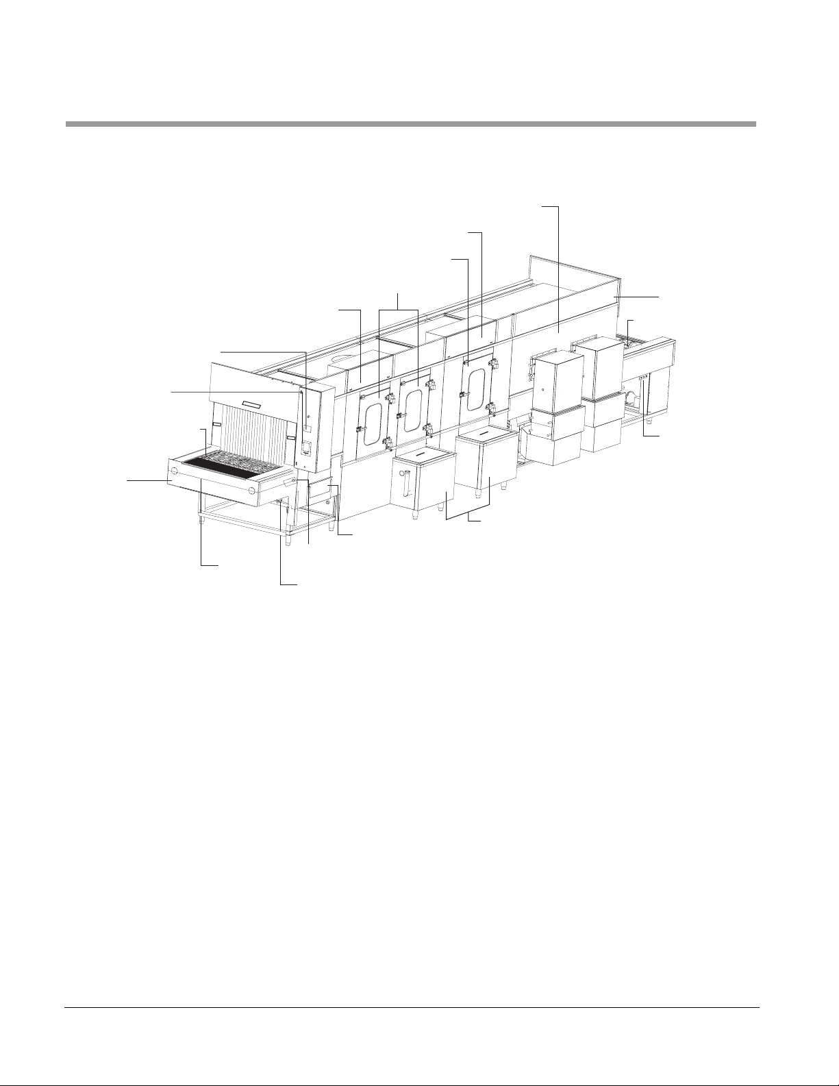
EXTERNAL COMPONENTS
CONTROL BOX
ACCESS PANEL
CONTROL PA NE L
RECORDER/
PRINTER
(Option)
Figure 1–2. EXTERNAL COMPONENTS
SEVEN FOOT
RECIRCULATED
ELECRICAL
DISCONECT
SWITCH
RINSE CHAMBER
ACCESS DOOR
WASHER CHAMBER
ACCESS DOORS
AIR DRYER
UNLOAD END
CONVEYOR
CONVEYOR
LOAD END
Control Panel
Emergency Stop Cable
EMERGENCY
STOP CABLE
GREASE FITTINGS
BASKET TYPE
DRAWER TYPE
EMERGENCY
STOP RESET
GREASE FITTINGS
DEBRIS SCREEN
DEBRIS SCREEN
Provides a touch screen interface with the Programmable Logic Controller
(PLC) located in the control box. Enables the user to select, program, and
monitor processing cycles.
An emergency stop cable is provided at both the load and unload ends of
the unit to terminate all process and conveyance functions. Processing is
resumed by resetting the emergency stop cable and pressing the cycle start
button.
Each chamber access door is equipped with a disconnect switch to
terminate all processing and conveyance functions upon opening of any
door. Processing cannot be resumed unless all doors are fully closed.
Alarm (not shown)
1–4
Sounds an audible alert:
• when the emergency stop cable is pulled
• when a chamber access door is opened.
Page 15

Series 2200 Washers
Conveyor
Wash Chamber Access Doors
Rinse Chamber Access Door
Final Rinse Heat Exchanger
Drawer and Basket-Type Debris Filters
Agent Injection Ports (not shown)
Exhaust Plenum (not shown)
A stainless steel, flat wire conveyor runs the full length of the processing
chamber carrying soiled ware through the unit’s treatment stations.
Sprockets at both the load and unload ends provide positive belt tracking.
Belt tension and speed are adjustable.
Removable, side hinged splash proof doors provide easy access to unit
Wash Chamber
Removable, side hinged splash proof door provides easy access to unit
Rinse and Final Rinse Chambers.
Ensures that a minimum 180oF final rinse temperature is attained and
maintained. Should the final rinse temperature assurance set point not be
attained or maintained the variances are annunciated to the user.
The pre-wash, agent wash, and recirculated rinse treatments are filtered
through drawer or basket-type stainless steel screens to prevent plugged
spray jets. The screens are easily accessible for cleaning.
Three agent injection ports and dry electrical contacts are provided for
installation of automatic agent injection systems.
A stainless steel exhaust plenum is provided for exhausting the washer and
dryer through a single point connection. Each machine vent is provided with
its own individual manual damper.
Six-Foot Recirculated Air Dryer (not shown)
Seven-Foot 99% Plastic Cage Dryer
Ten-Foot Recirculated Air Dryer (not shown)
An insulated stainless steel six-foot long dryer section to recirculate hot air
to dry the load is provided. The system consists of a steam to air heat
exchanger, a single 5 HP blower capable of providing a 1600 CFM air flow
and a stainless steel plenum system. Moisture is eliminated by exhausting a
portion of the recirculated air to the facility exhaust system. Plastic cages
are delivered at the unload end 95% dry. All air ducting is stainless steel and
includes required manual dampers.
An insulated stainless steel seven-foot long dryer section to recirculate hot
air to dry the load is provided. The system consists of a steam-to-air heat
exchanger, a dual 5 HP blower capable of providing a 3200 CFM air flow
and a stainless steel plenum system. Moisture is eliminated by exhausting a
portion of the recirculated air to the facility exhaust system. The conveyor
belt is separated from the wash compartment to remove the excess water
remaining on the plastic cages exiting the recirculated air dyer. This system
delivers the plastic cages 99% dry at the discharge of the dryer, permitting
filling of the cage immediately.
An insulated stainless steel ten-foot long dryer section to recirculate hot air
to dry the load is provided. The system consists of a steam to air heat
exchanger, a dual 5 HP blower capable of providing a 3200 CFM air flow
and a stainless steel plenum system. Moisture is eliminated by exhausting a
portion of the recirculated air to the facility exhaust system. Plastic cages
are delivered at the unload end 95% dry. All air ducting is stainless steel and
includes required manual dampers.
61301603708 1–5
Page 16

General Description
Unload Roller Conveyor
Control Box Access Panel
Electrical Disconnect Switch
A stainless steel, roller type, gravity conveyor is at the output end of the unit
to facilitate unloading.
Permits access to the unit’s control box located above Washer Chamber
door. Box contains the programmable controller, fuses, contactors, relays,
etc., and other essential components of the unit’s electrical system. (Access
restricted to qualified personnel only).
An UL/CSA approved, non-fusible 3 pole, electrical disconnect switch is
provided in the primary control box to provide additional protection to the
facilities personnel. The disconnect switch incorporates a handle
mechanism mounted through the control box front access panel and is
sealed to a NEMA 4X water tight rating. The handle must be turned to the
“OFF” position, disconnecting the incoming electrical service prior to
accessing the internal control box components.
1–6
Page 17
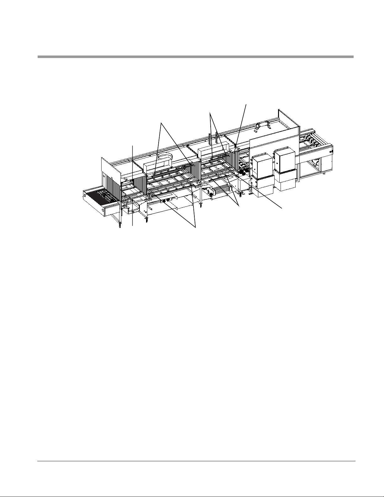
INTERNAL COMPONENTS
UPPER
SPRAY MANIFOLD
PREWASH STATION
Figure 1–3. INTERNAL COMPONENTS
UPPER
SPRAY MANIFOLD
WASH STATION
UPPER
SPRAY MANIFOLD
RINSE STATION
FINAL RINSE STATION
UPPER
SPRAY MANIFOLD
Series 2200 Washers
Upper Spray Manifold
Lower Spray Manifold
LOWER
SPRAY MANIFOLD
PREWASH STATION
A stationary, single manifold that delivers the jet spray and treatment agent
down on to soiled ware as it is conveyed through each station. These
manifolds are located in the following stations:
• Prewash
• Wash
• Rinse
• Final Rise
A stationary, single manifold that delivers the jet spray and treatment agent
up into soiled ware that is conveyed through each station. These manifolds
are located in the following stations:
• Prewash
• Wash
• Rinse
• Final Rise
SPRAY MANIFOLD
LOWER
SPRAY MANIFOLD
WASH STATION
LOWER
RINSE STATION
LOWER
SPRAY MANIFOLD
FINAL RINSE STATION
61301603708 1–7
Page 18

General Description
Hydraulic Hold Down (not shown)
Wash, Rinse, and Final Rinse Treatment Temperature Guarantees (not shown)
Water Conservation (not shown)
Jet spray header throttle valves are properly sized and positioned to
hydraulically hold down light plastic cage and steel pans to the conveyor. By
setting the throttle valve to restrict flow to the lower header, the pressure
differential will allow a higher volume of water to push down on caging.
An agent wash, recirculated rinse, or final rinse temperature guarantee may
be programmed to ensure that minimum treatment temperatures are
attained and maintained. Should the temperature guarantee set points not
be attained or maintained, the conveyer belt will temporarily stop until the
treatment solution reaches the set point temperature. The controls signal
the user if there are any variances.
The hot tap final rinse water is sprayed through the jet system and collected
in the recirculated rinse tank. The water is used for the recirculated wash,
rinse and pre-wash for water and energy conservation.
1–8
Page 19

MOST COMMON OPTIONS
Series 2200 Washers
Stainless Steel Treatment Components
House Tap Water Temperature Booster
Steam and Water Pressure Gauges
Automatic Self Cleaning Debris Filter
Automatic Drain System
Drain Discharge Cool Down Injection System
Washer Interior Cleaning and Descaling System
All components including valves, pump, and piping that come in contact with
the recirculating treatment solution are 304 stainless steel to provide system
life and durability
An instantaneous steam to water heat exchanger is provided to raise the
house tap water supply temperature.
Pressure gauges are provided on the incoming steam and water lines to
monitor the facility utilities.
The output of the wash pump is provided with a self cleaning debris screen
having perforations smaller than the spray jets’ orifices to prevent plugged
jets. The debris filter is automatically controlled to filter the recirculated was
solution and to periodically back flush debris to the drain. The screen
element may be accessed without the use of tools.
Provides the capability to automatically drain the agent wash and
recirculated rinse tanks at the end of the processing period.
Cold tap water is automatically injected into the drain discharge to lower the
discharge temperature before entering into the building’s drain system.
Provided in the interior of each tank are jets to wash the walls of the tank to
remove debris build up. When activated the control system automatically
drains the wash tank, refills the tank with fresh water and a descaling agent,
and activates the belt and pumps for a user programmable period of time,
automatically draining and flushing each tank. This system reduces or
eliminates the need to clean the tanks manually.
Automatic Conveyor Stop
Recorder/Printer
A photoelectric switch is located at the end of the discharge conveyor to
automatically stop the conveyor drive when an item reaches the end of the
conveyor. A second photo eye may be located at the end of a bedding
dispenser, if equipped, user may program cycle to stop at end of washer or
dispenser. A stopped conveyor condition is visually annunciated to the user
on the control screen.
Issues a printed record of all pertinent cycle data, including treatment
functions, temperature, time and date. A Take-Up Reel is provided to
retrieve and rewind the print-out onto a spool. See also: Appendix A:
Recorder/Printer.
61301603708 1–9
Page 20

General Description
GENERAL MACHINE DESCRIPTION
At the start of the processing period, the user activates the unit for
automatic operation by turning on the main disconnect switch. The unit
automatically goes through a self diagnostic test then fills with fresh water
and heats to programmed temperature.
The user at this time can press the start prompt and place the load to be
cleaned on the stainless steel flat wire. The unit will automatically proceed
through the treatment process and deliver the items at the unload end of the
machine.
Automatic Treatment Cycle
Treatment Schedule
The standard treatment cycle consists of a pre-wash, an agent wash, a
recirculated rinse, final rinse, and recirculated air dry. All wash and rinse
treatments are recirculated under pump pressure. The cycle, once
activated, is completely automatic. Additional cycle treatment phases are
available.
PRE-WASH
Hot water from the recirculated rinse tank is directed through the upper and
lower jet spray headers under pump pressure to remove gross debris. This
solution is not recirculated and is sent to drain.
AGENT WASH
Hot chemical solution, from the wash tank, is recirculated through the wash
jet spray headers under pump pressure and retained in the wash tank.
Wash temperature is progammable up to 190
RECIRCULATED RINSE
Hot water from the rinse tank, is recirculated through the rinse jet spray
headers (top to bottom) under pump pressure and retained in the rinse tank.
Rinse temperature is programmable up to 190
NON-RECIRCULATED FINAL RINSE
Hot tap water from house supply is heated by a steam heat exchanger and
directed through separate final rinse jet spray headers under house supply
pressure and retained in the rinse tank for the recirculated rinse and pre-
wash. Final rinse temperature is manually adjustable to 195
o
F.
o
F.
o
F.
1–10
RECIRCULATED AIR DRY (Optional)
Hot air is recirculated through a finned steam coil and directed through flat
air knives. The dryer temperature is manually adjustable. Moisture is
eliminated by exhausting a portion of the recirculated air to the facility
exhaust system.
Page 21

Series 2200 Washers
Temperature Guarantee System
NOTE
When selected, this will cause the unit to fill and spray water normally for
that phase. If at any time the tank temperature should fall below setpoint, the
conveyor belt will stop until the temperature exceeds setpoint. Failure to do
so in a set period of time will generate a “too long to heat” alarm.
• Operation (conveyor/recirculation) pauses if:
1) the wash or rinse water temperature setpoints not be met, or
2) the contents of a wash or rinse tank drop below its low level limit.
Otherwise, the unit runs until stopped by operating personnel.
• Water supplies held in Wash and Rinse Tanks are re-used until drained at
the end of the day (or as required—a determination made by operating
personnel).
61301603708 1–11
Page 22

General Description
1–12
Page 23

INTRODUCTION
Section 2 The Control Panel
Your unit has one of the following control panels:
• TOUCH CONTROL PANEL (TCP), see page 2–2
• LED CONTROLLER, see page 2–12
• ELECTRO-MECHANICAL CONTROLS, see page 2–27
The control panel provides an interface linked to the Programmable Logic
Controller (PLC) in the control box.
Using the control panel, the user can:
• Program treatment temperatures.
• Select treatments.
• Start the unit.
• Monitor the status of unit operation.
• Drain the unit’s wash and rinse water tanks.
• Control conveyor operation.
In addition, supervisory personnel can:
• Access load counters and time display
• Protect cycle programming
61301603708 2–1
Page 24
The Control Panel
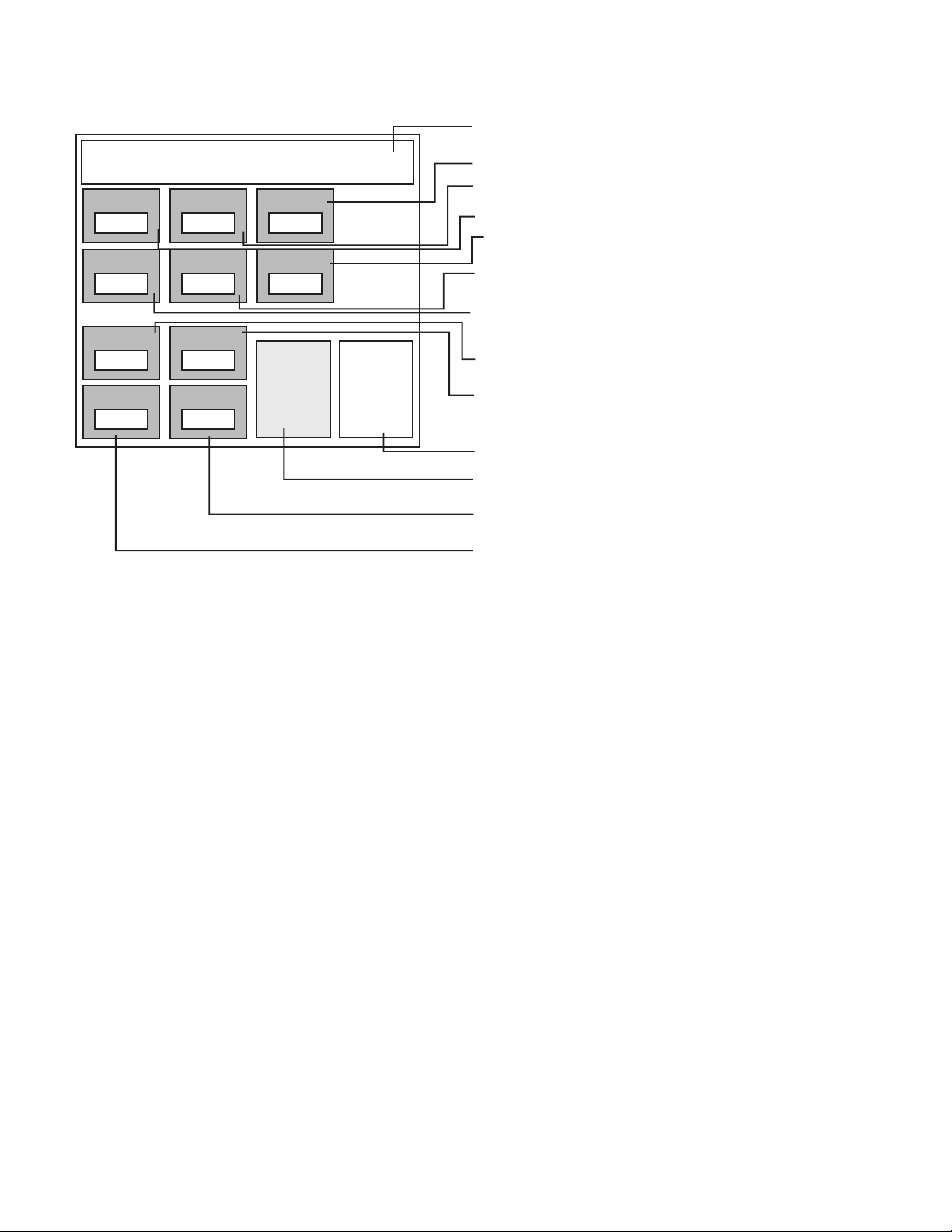
TOUCH CONTROL PANEL (TCP)
Control Screens
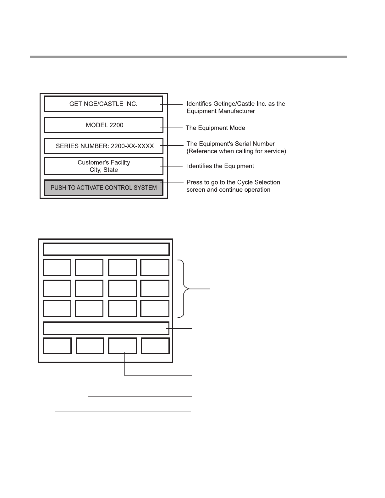
SELECT CYCLE FOR OPERATION
MAIN CONTROL SCREEN
CYCLE SELECTION SCREEN
Cycle
1
Cycle
5
Cycle
9
PUSH ANY BUTTON TO CONTINUE
MANUAL
MODE
Cycle
2
Cycle
6
Cycle
10
EVENT
PRINT OFF
Cycle
3
Cycle
7
Cycle
11
PRINT
CYCLE
Cycle
4
Cycle
8
Cycle
12
REVIEW
CYCLE
Press the desired cycle of operation
Press to start the automatic drain and shut down
operation. You will be directed to the Automatic
Shut down Cycle screen to begin this process
After a cycle is selected, press to review the
cycle and show the CYCLE START prompt
Press to print cycle parameters
When selected, prints live readings
during the cycle
Press to enter manual mode, to test
functions
2–2
Page 25
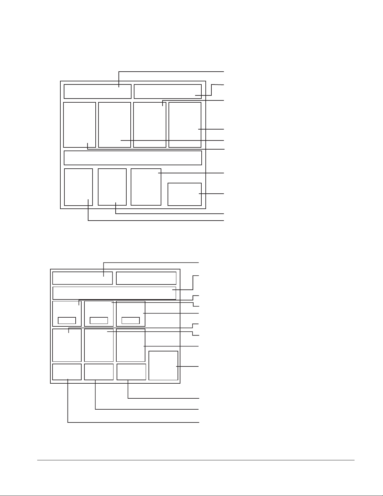
REVIEW PROGRAMMED PHASES SCREEN
Shows the selected cycle
Series 2200 Washers
CYCLE 1
RECIRCUL'D
WASH
SYSTEM OFF
REVIEW, START OR PROGRAM
MAIN
MENU
RECIRCUL'D
RINSE
SYSTEM OFF
START
MODE
REVIEW PROGRAMMED
PHASES
FINAL
RINSE
SYSTEM OFF
PROGRAM
CYCLE
AIR DRYER
SYSTEM OFF
PRINT
CYCLE
Shows the current TCP Screen
Shows the final rinse status
Shows the dryer status
Shows the rinse status
Shows the wash status
Press to enter the access screen
and program the selected cycle
Press to print cycle parameters
Press to start the selected cycle
Press to return to the main menu
Shows the cycle selected
CYCLE 1
WASH
TEMP
185
WASH
SYSTEM
ON
MAIN
MENU
AUTOMATIC CYCLE
NO ACTIVE ALARMS EXIST
RINSE
TEMP
185
RINSE
SYSTEM
ON
START
CYCLE
FR
TEMP
185
FINAL
RINSE
SYSTEM
ON
ANSWER
ALARM
CYCLE
ABORT
Any errors or alarms during
operation display here
Displays the current temperature of the Wash
Displays the current temperature of the Rinse
Displays the current temperature of the Final Rinse
Displays the status of the Wash
Displays the status of the Rinse
Displays the status of the Final Rinse
Press to stop all functions and sound alarm
Press to acknowledge all alarms
Press to start the cycle
Press to return to the Main Control Screen
61301603708 2–3
Page 26
The Control Panel
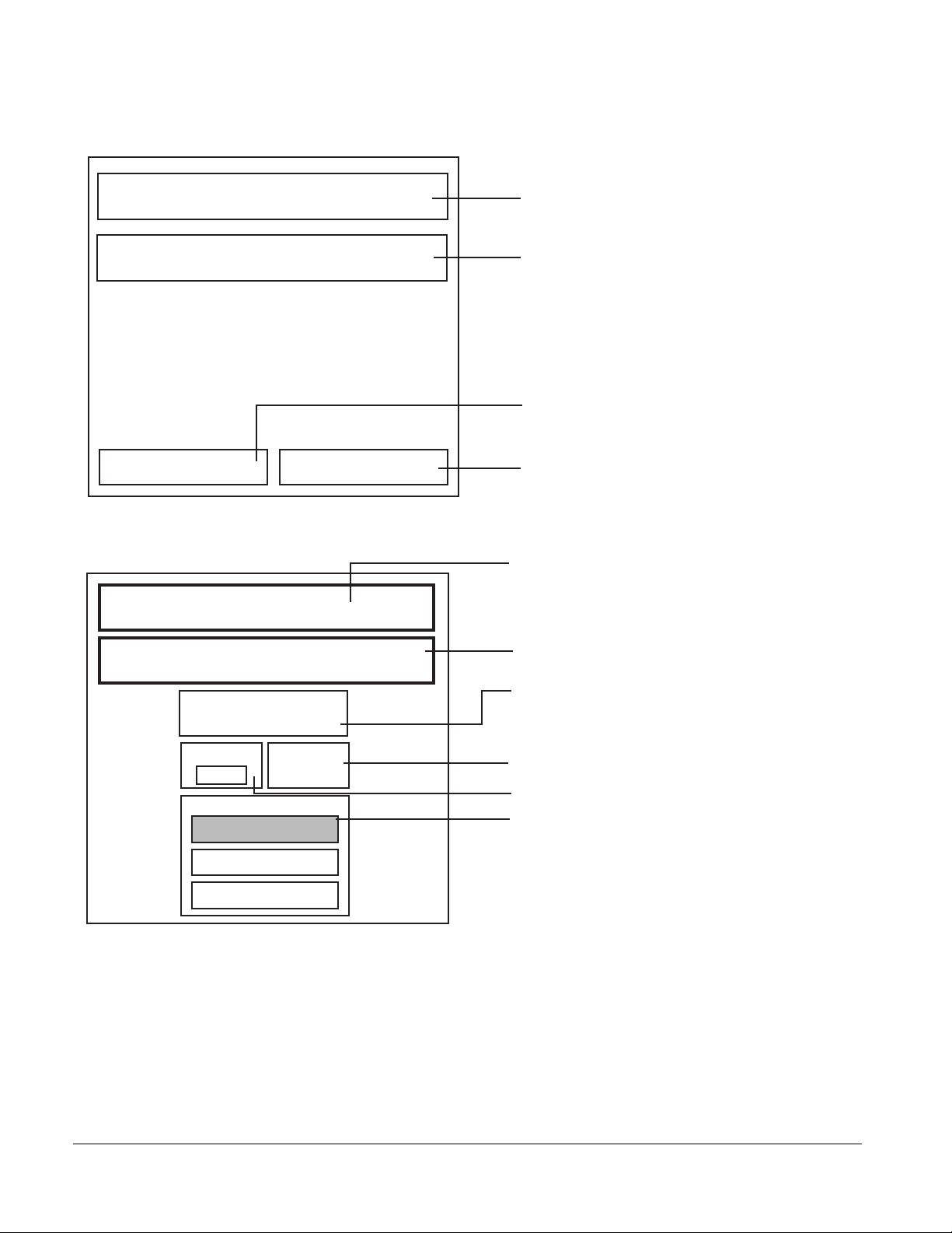
AUTOMATIC SHUT DOWN CYCLE SCREEN
AUTOMATIC SHUT DOWN CYCLE
Depress START or ABORT OPERATION
START
Automatic shut down
ABORT
PROGRAM RECIRCULATED WASH SCREEN
CYCLE 1
Shows the current TCP screen
Describes the actions available
Press to start automatic shut down
Press to stop automatic shut down
Shows the current cycle
Program Recirculated Wash Menu
Shows the screen function
Turns on or off wash treatment chamber
Recirculated agent Wash
On
Tank Temp Te mp
165
AGENT SELECTION
AKALINE AGENT
ACID AGENT
Guarantee
NO AGENT
NOTE: SOME FEATURES SHOWN ON THE TOUCH PANEL MAY NOT BE AVAILABLE IF
OPTIONS WERE NOT SELECTED.
Turns on or off the temperature guarantee
Changes the temperature in the wash tank
Select an alkaline wash,
acid wash, or no agent
2–4
Page 27
CYCLE 1
Series 2200 Washers
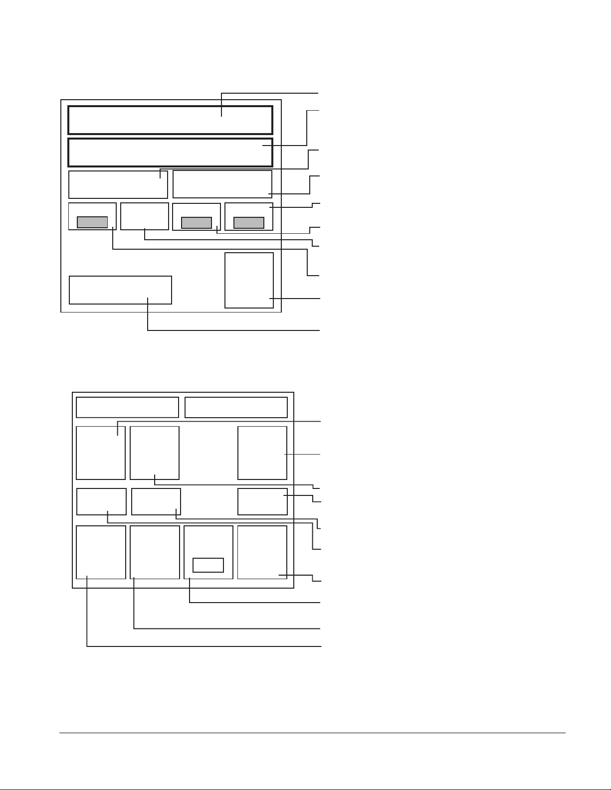
PROGRAM RINSE, FINAL RINSE AND DRYER SCREEN
Shows the current cycle
Shows the screen function
PROGRAM RINSE & DRYER
RECIRCULATED
RINSE ON
Ta n k Te mp
185
Guarantee
No Temp
GUARANTEE ON
FR Temp
DRYER
ON
CYCLE PASSWORD
Enter
Password
Change
Password
FINAL RINSE
Clean
185
300
MAIN
MENU
ACCESS SCREEN
SERVICE PASSWORD
Service
Password
Shows status of Recirculated Rinse
Press to change status
Shows status of Final Rinse
Press to change status
Sets time to descale the chamber interior
Sets the final rinse temperature
Shows status of the recirculated rinse guarantee
Press to change status
Sets the rinse tank temperature
Returns to the main menu
Shows status of the Dryer
Press to change status
Press and enter the password to unlock the
operator's program
Only for Factory authorized personnel
Changes the operator's password
This program is read only, showing the status of
program access (LOCKED )
Unlocked
Press to
change
P/W
LOCKED
Changes the password to unlock the
Program
Cycle
MAIN
MENU
Event Print
Frequency
300
Adjust
Calendar
Clock
operator's program
This program is read only, showing the status of
program access (UNLOCKED )
Sets the time and date
Sets the frequency (in seconds) of the printing
of live readings of the chamber temperature
Returns to MAIN MENU
Allows access to the programming screens
(after unlocking with ENTER PASSWORD)
CALENDAR CLOCK
61301603708 2–5
Page 28
The Control Panel
g
Displays the current screen description
CALENDAR CLOCK-ENTER NEW VALUES
THEN PRESS “SAVE CHANGES” PROMPT
PLC Month12PLC Day
10
New Month
10
PLC Hour10PLC Minute
New Hour9New Minute
New Day
1
56
14
PLC Year
00
New Year
01
SAVE
CHANGES
BACK TO
ACCESS
SCREEN
Displays current Year
Displays current Day
Displays current Month
(read-only)
(read-only)
(read-only)
Press to change the Year
Press to change the Day
Press to change the Month
Displays current Hour
Displays current Minute
(read-only)
(read-only)
Press to return to the Main Access Screen
Press to save all changes made in this screen
Press to change the Minute
Press to chan
e the Hour
2–6
Page 29

MANUAL MODE SCREEN
Series 2200 Washers
MANUAL MODE
Wash
Pump
Wash Tank
Fill
Wash Tank
Steam
Wash
Drain
Wash Tank
Flush
• Press any prompt to activate a selected component.
• Press the prompt again to stop the selected component,
or press ABORT to stop all activated components.
Rinse
Pump
Rinse Tank
Fill
Rinse Tank
Steam
Rinse
Drain
Rinse Tank
Flush
Select Desired
Function/Abort to Quit
Drive
System
Dryer
System
Back Flush
Valves
MAIN
MENU
Alkaline
Agent
Pump
Acid Agent
Pump
Neut.
Pump
ABORT
• All safety interlocks are intact in the manual mode. The wash or rinse
pumps do not operate if there is not enough water in the tank.
• Tank fill does not activate if the tank is full.
• Tank fill stops when the tank is full.
• Drains remain open until a prompt is pressed again
or until the screen is changed.
• Wash and rinse tank steam shut off when the programmed temperature
is reached.
• When the rinse pump is activated, the final rinse is activated.
• For more on manual screens, see on page -1.
61301603708 2–7
Page 30
The Control Panel
Cycle Programming
Example: Programming a Sample Cycle
PHASE
(NS)
The following is a SAMPLE cycle along with detailed instructions on how to
program the cycle for your reference.
On/Off
(NS)
TEMPERATURE (°F)
TEMPERATURE
GUARANTEE
AGENT
Sample Cycle 1—Touch Control Panel
Pre-wash
Wash On 140 Guaranteed Alkaline
Recirculated Rinse On 180 Off
Final Rinse On
Recirculated Air Dryer On
180
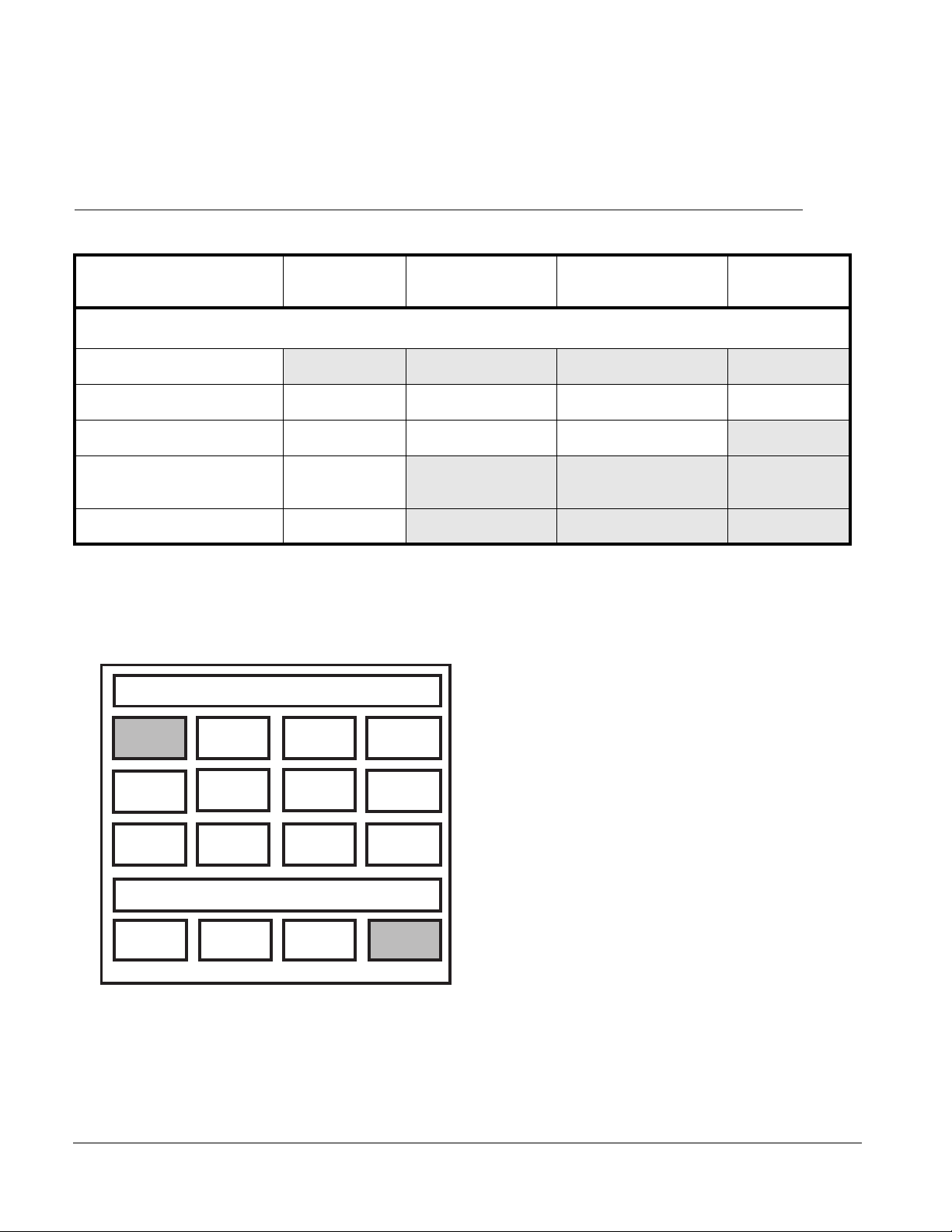
WHEN THIS SCREEN APPEARS
CYCLE SELECTION SCREEN
SELECT CYCLE FOR OPERATION
Cycle
1
Cycle
5
Cycle
9
PUSH ANY BUTTON TO CONTINUE
MANUAL
MODE
Cycle
2
Cycle
6
Cycle
10
EVENT
PRINT OFF
Cycle
3
Cycle
7
Cycle
11
PRINT
CYCLE
Cycle
4
Cycle
8
Cycle
12
REVIEW
CYCLE
FOLLOW THESE STEPS
1. Press CYCLE 1
2. Select REVIEW CYCLE
2–8
Page 31

Series 2200 Washers
WHEN THIS SCREEN APPEARS
CYCLE REVIEW SCREEN
CYCLE 1
RECIRCUL'D
WASH
SYSTEM OFF
RECIRCUL'D
RINSE
SYSTEM OFF
REVIEW, START OR PROGRAM
MAIN
MENU
START
MODE
REVIEW PROGRAMMED
PHASES
FINAL
RINSE
SYSTEM OFF
PROGRAM
CYCLE
AIR DRYER
SYSTEM OFF
PRINT
CYCLE
FOLLOW THESE STEPS
➢ Select PROGRAM CYCLE to enter the
CYCLE ACCESS SCREEN
CYCLE ACCESS SCREEN
CYCLE PASSWORD
Enter
Password
UNLOCKED
Program
Cycle
Change
Password
Press to
change
P/W
MAIN
MENU
SERVICE PASSWORD
Service
Password
LOCKED
Event Print
Frequency
Adjust
Calendar
300
Clock
1. Press ENTER PASSWORD
2. Unlock the system.
a. Type in correct password “12345”.
b. Press ENTER.
c. Press DONE.
3. Select PROGRAM CYCLE
61301603708 2–9
Page 32

The Control Panel
WHEN THIS SCREEN APPEARS
PROGRAM WASH PHASE SCREEN
CYCLE 1
Program Recirculated Wash Menu
Recirculated Agent
Wash On
Tank Temp Temp
140
AGENT SELECTION
AKALINE AGENT
Guarantee
FOLLOW THESE STEPS
1. Press RECIRCULATED AGENT WASH to ON.
2. Press TANK TEMP, set desired temperature.
3. Press TEMP GUARANTEE to ON if desired.
4. Toggle agent to desired agent.
5. Press NEXT PHASE button when all parameters
are set.
NEXT
PHASE
PROGRAM RINSE PHASE SCREEN
CYCLE 1
PROGRAM RINSE & DRYER
RECIRCULATED
RINSE ON
Ta n k Te mp
180
Guarantee
DRYER
ON
No Temp
FINAL RINSE
GUARANTEE ON
1. Press RECIRCULATED RINSE to ON.
2. Press TANK TEMP. Set desired temperature.
3. Press FINAL RINSE GUARANTEE to ON.
4. Press FR TEMP. Set desired temperature.
5. Press DRYER ON. Set desired temperature.
6. Press MAIN MENU to return to ACCESS MENU.
FR Temp
180
MAIN
MENU
2–10
Page 33

Series 2200 Washers
WHEN THIS SCREEN APPEARS
CYCLE ACCESS SCREEN
CYCLE PASSWORD
Enter
Password
Unlocked
Program
Cycle
Change
Password
Press to
change
P/W
MAIN
MENU
SERVICE PASSWORD
Service
Password
LOCKED
Event Print
Frequency
Adjust
Calendar
300
Clock
FOLLOW THESE STEPS
➢ Press MAIN MENU to return
to CYCLE SELECTION SCREEN.
61301603708 2–11
Page 34

The Control Panel
LED CONTROLLER
Key Locations
DISPLAY
STATUS LIGHTS
START
ABORT
MANUAL
MODE
Wash
Fill
Wash
Heat
Rinse
Rinse
Heat
Fill
SELECT
CYCLE
ENTER
SERVICE
MODE
SILENCE
ALARM
FUNCTIONS
MESSAGE
ALARM
GETINGE CASTLE, INC. MTP MODEL 22XX
TUNNEL, CAGE, AND UTENSIL WASHERS
REVIEW
CYCLE
EXIT
SERVICE
MODE
EVENT
PRINT
ON/OFF
PROGRAM
CYCLE
AUTO
DRAIN
PRINT
CYCLE
LAST
MESSAGE
NEXT
MESSAGE
PAG E
UP
PAG E
DOWN
PRINT
SCREEN
SETUP
HELP
➧
12
ALARM
➧
ACK
4
56
➧
7
±
DATA ENTRY
8
0
PRINTRUN
+
➧
-
TOGGLE
CLEAR
3
DELETE
E
9
N
T
E
R
.
2–12
The above screen has been separated into 3 sections:
• Status Lights, see page 2–13
• Function keys, see page 2–14
• Data Entry keys, see page 2–15
Information on each section follows.
Page 35

Status Lights
Series 2200 Washers
Wash
Fill
Wash
Heat
Rinse
Fill
Rinse
Heat
FUNCTION KEY FUNCTION
Wash Fill Status light indicates when tank is filling
Wash Heat Status light indicates when tank is heating
Rinse Fill Status light indicates when tank is filling
Rinse Heat Status light indicates when tank is heating
Status Light Not used
Status Light Not used
Status Light Not used
Status Light Not used
61301603708 2–13
Page 36

The Control Panel
Function Keys
START
ABORT
MANUAL
MODE
SELECT
CYCLE
ENTER
SERVICE
MODE
SILENCE
ALARM
REVIEW
CYCLE
EXIT
SERVICE
MODE
EVENT
PRINT
ON/OFF
PROGRAM
CYCLE
AUTO
DRAIN
PRINT
CYCLE
FUNCTION KEY FUNCTION
START Start the selected cycle.
ABORT Stop all functions of washer.
MANUAL MODE Enter the manual mode.
SELECT CYCLE Access cycle selection screen.
ENTER SERVICE
MODE
For authorized service technician only.
SILENCE ALARM Silence audible alarm.
REVIEW CYCLE Review selected cycle.
EXIT SERVICE
MODE
EVENT PRINT
ON/OFF
Exit service mode and return to stand-by
screen.
Record live readings of selected cycle as
load is being processed.
PROGRAM CYCLE Access selected cycle program for
parameter changes.
AUTO DRAIN Activate automatic drain system.
PRINT CYCLE Print parameters of selected cycle.
2–14
Page 37

Data Entry Keys (keypad)
Series 2200 Washers
LAST
MESSAGE
NEXT
MESSAGE
LAST
MESSAGE
NEXT
MESSAGE
PAG E
PAG E
DOWN
Used to review last screen
Used to review next
available screen
UP
PRINT
SCREEN
12
ALARM
➧
SETUP
HELP
ACK
4
7
±
Key/Function
HELP
Used to receive help
information
±
Used for the #2 or
to move cursor up
2
➧
56
➧
8
0
+
➧
-
TOGGLE
3
9
.
CLEAR
DELETE
E
N
T
E
R
-
TOGGLE
Used for the #9
9
Used to activate components or deactivate compo-
.
nents in Manual Mode.
PAG E
UP
PAG E
DOWN
SETUP
Used to scroll to
previous page
Used to scroll to next page
Used for the #1
Used for the #4 or
to move cursor left
Used for the #7 or
place TCP into direct
7
MODEM contact
ALARM
ACK
+
Used for the #5
5
Used for the #8 or
to move cursor down
8
Used for the #0
0
Used for the #3
3
Used for the #6 or
to move cursor right
6
CLEAR
DELETE
E
N
T
E
R
Used to clear old
parameters
Not used
Used to enter new
parameter
61301603708 2–15
Page 38

The Control Panel
Control Sequences
START UP
Turn the power ON to the unit. The unit runs a diagnostic test.
Once the controller runs the test, the display screen shows
“Getinge/Castle
Model 22XX Tunnel and Cage Washer.
MTP
The unit is now in the standby mode and ready to be used or
programmed.
PROGRAMMING
1. The user can program up to 12 different cycles. To begin,
press SELECT CYCLE. Press CLEAR on the key pad, and
input a cycle between 1 through 12 to be programmed,
then press ENTER. This brings up the Review Cycle
screen. The user can review the phases of the cycle by
pressing the PAGE UP and PAGE DOWN buttons on the
key pad.
2. The Prewash phase has fixed settings and cannot be
altered. The prewash water is generated from the
Recirculated Rinse phase. If the Recirculated Rinse phase
is turned OFF, the Prewash phase will also be turned OFF.
3. The Wash phase can be turned ON/OFF using the
TOGGLE button on the key pad. Toggle the wash phase to
ON. Use the arrow keys, on the keypad, to move the cursor
to each item of the phase. Enter the desired water
temperature and turn temperature guarantee ON/OFF (as
needed). Select detergent type and press ENTER. Press
the PAGE DOWN button to go on to the Recirculated Rinse
phase.
2–16
4. The Recirculated Rinse phase can be turned ON by using
the TOGGLE button on the key pad. Enter the desired
water temperature and turn temperature guarantee ON/
OFF (as needed). Press ENTER. Press the PAGE DOWN
button to go to the Final Rinse phase.
5. The Final Rinse phase is always ON. Enter the desired
water temperature and turn temperature guarantee ON/
OFF (as needed). Press ENTER. Press the PAGE DOWN
button to go on to the Recirculated Air Dry phase.
6. The Recirculated Air Dry phase can be turned ON by using
the TOGGLE button on the key pad. Press ENTER. Press
the PAGE DOWN button to go on to the clock set and
password screen, or if programming is complete, press
ABORT to exit the program mode.
7. The clock set settings are entered in the same way as the
time and temperature are done. Press CLEAR, key in new
Page 39

Series 2200 Washers
settings, and press ENTER. Use arrow keys to move
between settings which need to be changed. Press SAVE
SETTINGS to save new clock settings. Press the PAGE
DOWN button to go on to the password screen, or if
programming is complete, press ABORT to exit the
program mode.
8. The user can input up to a five-digit password (between
0-32000). Press CLEAR, enter the new password, and
press ENTER. Press ABORT to exit program mode.
STARTING WASH CYCLE
To start the unit, the user chooses a preprogrammed cycle by
pressing SELECT CYCLE. Press CLEAR on the key pad, and
input a cycle between 1 and 12, and press ENTER. Press the
START button on the key pad to run the cycle.
ALARM
If an alarm should sound at any time, press SILENCE ALARM
to turn the sound off, then follow the prompt on the display
screen to solve the problem. Press ALARM ACK on the keypad
to return to the program.
HELP
A help screen is provided to assist the user. Press the HELP
button on the keypad for more information on a particular
function.
61301603708 2–17
Page 40

The Control Panel
Processing Cycle Screen Description
Standby Screen
Wash
Fill
MESSAGE
ALARM
PRINTRUN
Rinse
Wash
Rinse
Heat
Heat
Fill
GETINGE CASTLE, INC. MTP MODEL 22XX
TUNNEL, CAGE, AND UTENSIL WASHERS
SELECT CYCLE
START
ABORT
MANUAL
MODE
SELECT
CYCLE
ENTER
SERVICE
MODE
SILENCE
ALARM
REVIEW
CYCLE
EXIT
SERVICE
MODE
EVENT
PRINT
ON/OFF
PROGRAM
CYCLE
AUTO
DRAIN
PRINT
CYCLE
LAST
MESSAGE
NEXT
MESSAGE
PAG E
UP
PAG E
DOWN
PRINT
SCREEN
12
ALARM
➧
ACK
4
SETUP
7
HELP
±
➧
➧
From the Standby Screen, choose:
1) SELECT CYCLE to select the desired cycle
2) REVIEW CYCLE to review parameters of selected cycle.
3) MANUAL MODE to test functions of individual components.
+
CLEAR
3
DELETE
➧
56
-
9
8
TOGGLE
.
0
E
N
T
E
R
2–18
From Standby Screen (shown above)
Press SELECT CYCLE button (screen shown below).
1. Press CLEAR.
2. Enter the number of the desired cycle (1 through 12)
3. Press ENTER.
Page 41

Series 2200 Washers
REVIEW CYCLE
REVIEW SCREEN #1.
Press PAGE DOWN to view all parameters of the selected cycle
REVIEW SCREEN #2
Press PAGE DOWN to view all parameters of the selected cycle
REVIEW SCREEN #3
Press PAGE DOWN to view all parameters of the selected cycle
REVIEW SCREEN #4
Press PAGE DOWN to view all parameters of the selected cycle
REVIEW SCREEN #5
Press PAGE DOWN to view all parameters of the selected cycle
REVIEW SCREEN #6
Press PAGE DOWN to view all parameters of the selected cycle
61301603708 2–19
Page 42

The Control Panel
MANUAL MODE
Manual mode allows the user or maintenance technician to test the
functions of individual components
When MANUAL MODE is selected, the screen shows individual
components that may be activated or deactivated. More than one
component may be activated or deactivated at the same time. Press PAGE
DOWN or PAGE UP to view more components.
To activate or deactivate a component in Manual Mode:
1. Press PAGE DOWN or PAGE UP until the desired component shows.
2. Use the arrow keys to move the cursor to the desired component.
3. To activate the component, press TOGGLE when the cursor is under
the deactivated component.
4. To deactivate a component, press TOGGLE when the cursor is under
the activated component.
5. To deactivate all components and return them to standby, press
ABORT.
MANUAL SCREEN #1
MANUAL SCREEN #2
MANUAL SCREEN #3
MANUAL SCREEN #4
2–20
Page 43

Cycle Programming
Wash
Series 2200 Washers
Rinse
Wash
Rinse
Heat
Heat
Fill
Fill
GETINGE CASTLE, INC. MTP MODEL 22XX
TUNNEL, CAGE, AND UTENSIL WASHERS
MESSAGE
ALARM
PRINTRUN
START
ABORT
MANUAL
MODE
SELECT
CYCLE
ENTER
SERVICE
MODE
SILENCE
ALARM
REVIEW
CYCLE
EXIT
SERVICE
MODE
EVENT
PRINT
ON/OFF
PROGRAM
CYCLE
AUTO
DRAIN
PRINT
CYCLE
LAST
MESSAGE
NEXT
MESSAGE
PAG E
UP
PAG E
DOWN
PRINT
SCREEN
12
ALARM
➧
4
SETUP
7
HELP
±
➧
➧
ACK
56
➧
8
TOGGLE
0
+
CLEAR
3
DELETE
-
E
9
N
T
E
R
.
From the Standby Screen the user may change the parameters of the cycle
by following these steps:
1. Press SELECT CYCLE.
2. Press CLEAR.
3. Key in the cycle number.
4. Press ENTER.
5. Press the PAGE DOWN or PAGE UP buttons until the screen shows
the phase were the change needs to be made.
6. Use the arrow keys to move the cursor to the parameter that needs to
be changed
7. Press CLEAR.
8. Enter new time or temperature.
9. Press TOGGLE to turn ON/OFF status of phase.
10. Press ENTER to enter all changes.
When all desired changes have been made:
11. Press REVIEW CYCLE to review changes or “PROGRAM CYCLE” to
return to the standby screen
12. If equipped with a printer, press PRINT CYCLE to record new
parameters on paper printout.
61301603708 2–21
Page 44

The Control Panel
Cycle Selection
From Standby Screen (shown above)
Press SELECT CYCLE button (screen shown below).
1. Press CLEAR.
2. Enter the number of the desired cycle (1 through 12)
3. Press ENTER.
4. Press PROGRAM CYCLE.
Programming a Cycle
5. Press PAGE UP or PAGE DOWN until the desired screen appears.
PROGRAM SCREEN #1.
1. Use the arrow keys to move the cursor to the parameter to be changed.
Press TOGGLE to turn selection ON/OFF.
2. Press CLEAR, key in new setting, then press ENTER to change
parameters.
PROGRAM SCREEN #2.
1. Press PAGE DOWN to view the parameters of selected cycle.
2. Use the arrow keys to move the cursor to the parameter to be changed.
Press TOGGLE to turn selection ON/OFF.
2–22
3. Press CLEAR, key in new setting, then press ENTER to change
parameters.
Page 45

Series 2200 Washers
PROGRAM SCREEN #3.
1. Press PAGE DOWN to view the parameters of selected cycle.
2. Use the arrow keys to move the cursor to the parameter to be changed.
Press TOGGLE to turn selection ON/OFF.
3. Press CLEAR, key in new setting, then press ENTER to change
parameters.
PROGRAM SCREEN #4.
1. Press PAGE DOWN to view the parameters of selected cycle.
2. Use the arrow keys to move the cursor to the parameter to be changed.
Press TOGGLE to turn selection ON/OFF.
3. Press CLEAR, key in new setting, then press ENTER to change
parameters.
PROGRAM SCREEN #5.
When setting new parameters for DATE AND TIME, enter desired changes,
toggle SAVE SET to ON, and press ENTER.
PROGRAM SCREEN #6.
To protect the program from unauthorized changes, enter a password here
to lock out access to the PROGRAMING CYCLE phase of the program.
61301603708 2–23
Page 46

The Control Panel
Example: Programming a Sample Cycle
PHASE On/Off TEMPERATURE (°F)
The following is a SAMPLE cycle along with detailed instructions on how to
program the cycle for your reference.
TEMPERATURE
GUARANTEE
AGENT
Sample Cycle 1—LED Controller
Pre-wash
Wash On 165 Guaranteed Alkaline
Recirculated Rinse On 180 Off
Final Rinse On 180 Guaranteed
Recirculated Air Dryer On
Rinse
Wash
Rinse
Wash
Fill
Heat
Heat
Fill
MESSAGE
ALARM
PRINTRUN
GETINGE CASTLE, INC. MTP MODEL 22XX
TUNNEL, CAGE, AND UTENSIL WASHERS
START
ABORT
MANUAL
MODE
SELECT
CYCLE
ENTER
SERVICE
MODE
SILENCE
ALARM
REVIEW
CYCLE
EXIT
SERVICE
MODE
EVENT
PRINT
ON/OFF
PROGRAM
CYCLE
AUTO
DRAIN
PRINT
CYCLE
LAST
MESSAGE
NEXT
MESSAGE
PAG E
UP
PAG E
DOWN
PRINT
SCREEN
12
ALARM
➧
ACK
4
SETUP
7
HELP
±
+
➧
➧
56
➧
-
8
TOGGLE
0
CLEAR
3
DELETE
E
9
N
T
E
R
.
Start Up Turn the power ON to the unit. At this time, the unit will go
through a diagnostic test. Once the controller runs the test, the
display screen will show, “Getinge Castle, Inc. MTP Model 22XX
Tunnel and Cage Washer.” The unit is now in the standby mode
and ready to be used or programmed.
Programming 1. The user can program up to 12 different cycles. To begin,
press SELECT CYCLE. Press CLEAR on the key pad,
input a cycle between 1 through 12 to be programmed,
then press ENTER. This will bring up the Review Cycle
2–24
Page 47

Series 2200 Washers
screen. Using PAGE UP and PAGE DOWN on the key pad,
the user can review each phase of that cycle. If the cycle
needs to be programmed or changed, press PROGRAM
CYCLE. You are now ready to program each phase of the
sample cycle noted on the previous page.
2. The Prewash phase has fixed settings and cannot be
altered. The prewash water is generated from the
Recirculated Rinse phase. If the Recirculated Rinse phase
is turned OFF, the Prewash phase will also be turned OFF.
3. The Wash phase can be turned ON/OFF by using the
TOGGLE button on the key pad. Toggle the wash phase to
ON. Use the arrow keys, on the keypad, to move the cursor
to each item of the phase. Move the cursor to
TEMPERATURE, press CLEAR, input 165, and press
ENTER. Move the cursor to GUARANTEE and toggle ON.
Move the cursor to AGENT and toggle to ALKALINE. Once
you have completed the wash phase, press PAGE DOWN
to go on to the Recirculated Rinse phase.
4. The Recirculated Rinse phase can be turned ON/OFF by
using the TOGGLE button on the key pad. Move the cursor
to TEMPERATURE, press CLEAR, input 180, and press
ENTER. Move the cursor to GUARANTEE and toggle OFF.
Once you have completed the Recirculated Rinse phase,
press PAGE DOWN to go on to the Final Rinse phase.
5. The Final Rinse phase is always ON. Move the cursor to
TEMPERATURE, press CLEAR, input 185, and press
ENTER. Move the cursor to GUARANTEE and toggle ON.
Once you have completed the Final Rinse phase, press
PAGE DOWN to go on to the Recirculated Air Dryer phase.
6. The Recirculated Air Dry phase can be turned ON/OFF by
using the TOGGLE button on the key pad. Once you have
completed the Recirculated Air Dryer phase, press PAGE
DOWN button to go on to the Clock Set and Password
screen. If programming is complete, press ABORT to exit
program mode.
7. The Clock Set settings are entered in the same way as the
time and temperature are done. Press CLEAR, key in new
setting, and press ENTER. Use arrow keys to move
between settings which need to be changed. Press SAVE
SETTINGS to save new clock settings. Press PAGE DOWN
to go on to the Password screens. If programming is
complete, press ABORT to exit program mode.
61301603708 2–25
Page 48

The Control Panel
8. You can input up to a five digit password (between
0-32000). Press CLEAR, input the new password, and
press ENTER. Press ABORT to exit program mode.
Starting Wash Cycle To start the unit, choose a preprogrammed cycle by pressing
SELECT CYCLE. Press CLEAR on the key pad, input a cycle
between 1 through 12, and press ENTER. Press START button
on the key pad to run cycle.
Alarm If an alarm should sound at any time, press ALARM SILENCE
to turn the sound off, then follow the prompt on the display
screen to solve the problem. Press ALARM ACK on the keypad
to return to the program.
Help A help screen is provided to assist the user. Press the HELP
button on the keypad for more information on a particular
function.
2–26
Page 49

ELECTRO-MECHANICAL CONTROLS
Control Panel
Series 2200 Washers
61301603708 2–27
Page 50

The Control Panel
Item # Component
1. POWER Switch Turns power ON/OFF to the control
circuit. (Must be ON for the machine to
operate.)
2. START Starts an automatic cycle (after the
machine is ready and the start light is
ON).
3. STOP Stops all function of the unit without
sounding the alarm.
4. Low Water Level
Wash Tank
5. Low Water Level
Rinse Tank
6. Low Wash Temperature An indicator light only. Lights when the
7. Low Rinse Temperature An indicator light only. Lights when the
8. Low Final Rinse
Temperature
9. Emergency System
Activated
An indicator light only. Lights when the
wash fill timer times out. When indicator
is on, all functions stop except for the fill
operation.
An indicator light only. Lights when the
rinse fill timer times out. When this
indicator is on, all functions stop except
for the fill operation.
wash steam timer times out. When
indicator is ON, all functions stop except
for the heating operation.
rinse steam timer times out. When
indicator is ON, all functions stop except
for the heating operation.
An indicator light only. Lights when the
final rinse steam timer times out. When
indicator is ON, all functions stop except
for the heating operation.
An indicator light only. Lights when the
Emergency Cable at the load or unload
end of the machine has been pulled.
2–28
10. Door Open An indicator light only. Lights when one
or more of the chamber access doors
are opened. All doors must be closed
and safety reset switch activated before
unit will allow a restart.
Page 51

Series 2200 Washers
Item # Component
11. Conveyor Full An indicator light only. Lights when the
photo eye at the unload end is blocked.
When the indicator is ON, all functions of
the machine are active except for the
conveyor belt. When the obstruction is
removed, the conveyor belt resumes
operation.
12. Power An indicator light only. Lights when the
power switch is ON.
13. Machine Ready for
Operation
14. Wash Temperature This controls and monitors the heat in
15. Rinse Temperature This controls and monitors the heat in
16. Final Rinse Temperature This monitors the heat in the final rinse
An indicator light only. Lights when all
conditions are satisfied–wash and rinse
tanks are full and at set point
temperature. Only at this point should
the START button be pressed
the wash tank.The controller displays
the temperature as the machine is
running. Temperature settings may be
changed by pressing the up arrow or
down arrow key to the desired settings.
the rinse tank. The controller displays
the temperature as the machine is
running. Temperature settings may be
changed by pressing the up arrow or
down arrow key to the desired settings.
water. The controller displays the
temperature as the machine is running.
Temperature settings may be changed
by pressing the up arrow or down arrow
key to the desired settings. When the
temperature falls below the set point, the
final rinse steam timer starts to time. If
the set point is not achieved before the
timer times out, the conveyor belt stops
and LOW FINAL RINSE
TEMPERATURE lights.
61301603708 2–29
Page 52

The Control Panel
Cycle Programming
1. PreWash The prewash is powered by the rinse pump and only controlled by the hand valve located on the utility side load end.
2. Wash Section The wash is recirculated by the wash pump. The wash
pump will activate when in automatic cycle if water level is up to proper
level. The tank refills during processing from the wash tank fill valve.
3. Wash Temperature Controller Temperature controller is
programmable from 160° to 190°F. To change temperature, press the
arrow in the direction of desired change (up arrow to increase
temperature and down arrow to decrease temperature).
Figure 2–1. WASH TEMPERATURE CONTROLLER
4. Rinse Treatment pump The rinse is controlled by the rinse pump. The
rinse pump activates when in automatic cycle if water level is up to
proper level. The tank refills during processing from the rinse tank fill
valve. The rinse tank will normally not need to refill during the normal
processing period due to the constant flow of final rinse water flowing
into the rinse tank.
Final Rinse Temperature Settings
5. Rinse Temperature Controller Temperature controller is
programmable from 160° to 190°F. To change temperature, press the
arrow in the direction of desired change (up arrow to increase
temperature and down arrow to decrease temperature).
6. Final Rinse Temperature Controller Temperature controller is
programmable from 160° to 195°F.
1. Turn water to full open setting.
2. Turn steam to full open setting (temperature not to exceed 195°F).
3. If water at full open and steam at full open does not create an output
temperature of 195°F, turn water flow down until 195°F is achieved.
4. If water at full open and steam at full open exceeds 195°F, turn steam
throttle valve down until in 195°F range.
5. If temperature becomes unstable, turn the water pressure regulator
down to 5 psi lower than dynamic house pressure and repeat steps 1
to 4.
2–30
Page 53

Figure 2–2. WATER AND STEAM FLOW DIAGRAM
TEMPERATURE
GUAGE
STEAM
SOLENOID
WATER
THROTTLE
VALV E
STEAM FLOW
STEAM THROTTLE VALVE
Series 2200 Washers
VACUUM
BREAKER
WATER
SOLENOID
Internal Timers
WATER
PRESSURE
REDUCER
STEAM TRAP
DIRECTION OF
WATER FLOW
1. Wash Fill Timer times how long wash tank should require to fill. If
wash tank does not fill before timer times out unit will shut down.
2. Rinse Fill Timer times how long rinse tank should require to fill. If rinse
tank does not fill before timer times out unit will shut down.
3. Safety System Reset allows user to reset safety system after alarm
has been satisfied (closed door or by placing machine in stand by to
refill or heat) switch will return to normal position when released.
4. Wash Steam Timer times how long wash tank should need to reach
programmed temperature. If temperature is not achieved before timer
times out unit will shut down.
5. Rinse Steam Timer times how long rinse tank should need to reach
programmed temperature. If temperature is not achieved before times
out unit will shut down.
6. Final Rinse Timer times how long the final rinse needs to heat up to
the programmed temperature. If temperature is not achieved before
timer times out unit will shut down.
7. Variable Speed Controller controls the speed of the conveyor belt.
Turn knob located on the back side of the control panel clock wise to
minimum speed 2 feet per minute, maximum speed 10 feet per minute.
Figure 2–3. VARIABLE SPEED CONTROLLER
61301603708 2–31
Page 54

The Control Panel
2–32
Page 55

GENERAL MACHINE OPERATION
Instructions here apply to the daily operation of this unit. They assume that
the unit has been properly installed and pre-tested: that the compartment is
clean, cycle selections have been programmed, the liquid supplies are set
up, and any optional equipment is ready.
Section 3 Operating Instructions
WARNING
HS
• BURN HAZARD: Do not open chamber access doors during
a cycle. This could release hot water through the door
opening, resulting in burns to personnel.
• HOT SURFACES: The metal surface that surrounds the
opening at the load and unload end of unit becomes hot
during normal operation. Use caution when loading and
unloading the washer.
Start-up At the start of the processing period, activate the unit for auto-
matic operation:
Turn on the main disconnect switch.
• The unit automatically goes to a self diagnostic test
then fill with fresh water and start heating up to programmed temperature. When filling and heating are
complete the display shows “Ready for Operation”.
• Units with Touch Control Panel (TCP) only: The
Touch Control Panel (TCP) immediately lights and performs a self-diagnostic test. Once complete the system
Standby Screen displays and the machine is ready for
operation.
Operating Instructions 1. Place the load to be cleaned on the stainless steel flat wire
conveyor.
2. Select the desired cycle
(see “Treatment Schedule” on page 3–2).
3. Press the START button.
• The unit automatically proceeds through the treatment
process and delivers the items at the unload end of the
machine.
• A photoelectric switch at the end of the discharge con-
veyor automatically stops the conveyor drive when an
61301603708 3–1
Page 56

Operating Instructions
item reaches the end of the conveyor. A stopped conveyor condition is indicated on the control screen.
Shutdown At the end of the processing period, place the unit in the
standby mode:
Press the STOP button.
• All processing functions immediately stop and the
wash and rinse tanks automatically refill and maintain
heat.
Treatment Schedule
The treatment schedule is listed below. For additional information, refer to
“Treatment Schedule” on page 1–10. The process for the wash cycle is as
follows:
• Prewash
• Agent Wash
• Recirculated Rinse
• Non-Recirculated Final Rinse
• Recirculated Air Dry
3–2
Page 57

DAILY CHECKLIST
Series 2200 Washers
WARNING
HS
HOT SURFACES: The metal surface that surrounds the
opening at the load and unload end of unit is hot during normal
operation. To avoid burns, use caution when loading and
unloading the washer.
Before operating the unit each day:
1. Check the printer paper roll and replace it if necessary. See
page 7–4.
2. Clean the debris basket and drawers in the chamber drain.
See page 4–3
3. Check chemical supplies.
4. Clean drawer-type and basket-type debris filters.
5. Check the chemical dispenser (if the unit has the optional
Automatic Agent Injection System, see “Automatic Agent
Injection System” on page 7–10).
Operational Readiness To ensure that the washer is ready for processing without
requiring a warm-up period, leave the washer ON during
regular periods of inactivity.
61301603708 3–3
Page 58

Operating Instructions
EMERGENCY STOP
Burn hazard. Do not open a station access door for at least five
WARNING
HS
seconds after stopping a processing cycle that was running a
hot wash or rinse water phase. This allows time for the spray
manifolds to stop functioning; otherwise hot water could spray
out of the door opening, resulting in burns to personnel.
Using the Emergency Cable 1. Pull the EMERGENCY CABLE either at the load end or the
unload end.
• The unit ceases operation.
2. To resume operation, press EMERGENCY CABLE RESET
either at the load end or the unload end.
EMERGENCY SHUT-DOWN
Shutting Down the Washer
WARNING
In an emergency, it may be necessary to remove electrical power supplied
to the washer or to turn off the steam and water supplies. All users should
know the location of the main circuit breaker to disconnect the main
electrical power and the steam and water supply shutoff valves at the
washer site.
The Electrical Disconnect Switch de-energizes the controls
only; it does not remove all power from the washer.
3–4
Page 59

GENERAL MAINTENANCE SCHEDULE
The customer is responsible for these maintenance items at the intervals
specified. Optional items may require additional maintenance. Refer to your
Customer Manual for this information.
Table 4–1. Maintenance Schedule—Standard
PERFORMANCE ASSURANCE
PLAN
Preventive maintenance
performed by factory-trained
service representatives, using
authorized parts and service
techniques, is recommended.
Recognizing symptoms of
potential trouble and making
corrections immediately is less
costly and time consuming than
repairing damaged equipment.
Our Performance Assurance Plan
offers scientific maintenance, not
merely repair service.
For quality service on this
equipment and information on
our Performance Assurance
Plan, contact Getinge/Castle, Inc.
1777 East Henrietta Road,
Rochester, NY 14623-3133 or
call 1-800-950-9912.
A Service Data Manual for this
unit may be purchased from
Getinge/Castle, Inc.
• LOAD PRINT PAPER (option)
• TEST THE SAFETY SYSTEMS
• CLEAN THE PRIMARY DEBRIS FILTERS
• INSPECT THE AUTOMATIC SELF-
CLEANING DEBRIS FILTER SCREEN
AND TANK
• CLEAN THE SPRAY JETS AND
HEADERS
• INSPECT THE TEMPERATURE AND
WATER LEVEL PROBES FOR DEBRIS
AND DAMAGE
• GREASE THE SHAFT BEARINGS
• MAINTAIN THE CABINET
• OIL THE HOLD DOWN CHAIN
• LUBRICATE THE PUMP MOTOR
• CHECK AND ADJUST THE CONVEYOR
BELT TENSION
• CHECK THE GFI SENSOR
MAINTENANCE ITEM INTERVAL
Section 4 Maintenance
SEE
PAG E
WHEN
REQUIRED
DAILY 4–2
WEEKLY
MONTHLY 4–4
EVERY SIX
MONTHS
4–2
4–3
4–3
4–4
4–4
4–4
4–4
4–5
4–5
4–5
61301603708 4–1
Page 60

Maintenance
ROUTINE MAINTENANCE SCHEDULE—STANDARD
When required
Daily
NOTE
LOAD PRINT PAPER (option)
See “LOADING PAPER” on page 4.
TEST THE SAFETY SYSTEMS
Ensure that two (2) or more individuals are always present for this test.
1. Manually open each chamber access door in standby mode. Each time
the operator should observe:
a. alarm sounds
b. machine is disabled
2. Close the doors and reset the safety system.
3. Pull the EMERGENCY STOP cables on both the Load and Unload
Ends one at a time to test for functionality.Each time the operator
should observe:
a. alarm sounds
b. machine is disabled
4. Reset the EMERGENCY STOP cables and reset the safety system.
5. To reset after testing, the operator should turn on the safety reset system. (The switch does not return by itself.) The switch is on the back
side of the control panel.
4–2
Page 61

Series 2200 Washers
Figure 4–1. DRAWER-TYPE AND BASKET-TYPE DEBRIS FILTERS
CLEAN THE PRIMARY DEBRIS FILTERS
1. Remove the Primary Debris Filters – Two (2) Drawer-Type and Two (2)
Basket-Type.
a. Drawer Debris Filter (2) located at Load end of washer
b. Basket Debris Filters (2) located in front of Wash Chamber
Access Door and Rinse Chamber Access Door
2. Clean the debris from the filters with water.
3. Replace all three (3) Primary Debris Filters.
Figure 4–2. AUTOMATIC SELF-CLEANING DEBRIS FILTER
FILTER
HOUSING
O-RING
(see Spare Parts List for part no.)
FILTER SCREEN
(see Spare Parts List for part no.)
FILTER
HOUSING
CAP
INSPECT THE AUTOMATIC SELF-CLEANING DEBRIS FILTER SCREEN AND TANK
1. Turn power OFF.
2. Remove retainer clamp on filter cover
3. Remove the cover, gasket, and filter screen
4. Rinse any debris out of screen
5. Carefully place filter screen back into filter housing
6. Place gasket and cover on the assembly and secure retainer.
61301603708 4–3
Page 62

Maintenance
Weekly
CLEAN THE SPRAY JETS AND HEADERS
1. With power turned off, open Chamber Access Doors (a flashlight may
be needed).
2. If debris is present in jet, pull header out. Remove only one header at
a time.
3. Push the debris through the jet and into the header with a small wire.
4. Remove the flush plugs from the end of the spray headers.
5. Manually flush header in a sink to force loosened debris from the spray
headers
6. Reinstall flush plugs
7. Place header back into unit where it was removed from.
INSPECT THE TEMPERATURE AND WATER LEVEL PROBES FOR DEBRIS AND DAMAGE
1. Locate the temperature and water level probes in the wash and rinse
section tanks. (Accessed externally)
2. Drain wash and rinse tanks.
3. Remove tank cover for each tank.
4. Gently wipe off any debris around temperature and water level probes
with a cloth.
Monthly
NOTE
5. Replace tank cover for each tank.
GREASE THE SHAFT BEARINGS
1. Two grease fittings located at the load end and two at the unload end
near the bottom, giving the unit a total of four. Depending upon dryer
option there will be additional grease fittings in the beginning of the
dryer section that need to be greased.
2. Each grease fitting requires two pumps with a grease gun.
Grease should be Lithium#2 or equivalent.
MAINTAIN THE CABINET
To maintain cabinet luster, wipe down with non-abrasive stainless steel
cleaner in straight line with direction of grain.
OIL THE HOLD DOWN CHAIN
1. Run hold down to highest position
2. Using spray oil (WD-40), spray exposed chain on top of the machine.
4–4
Page 63

Series 2200 Washers
Six Months
WARNING
LUBRICATE THE PUMP MOTOR
Re-lubricate the sleeve with a high grade ball and roller bearing grease
every six to twelve months as indicated on the motor.
CHECK AND ADJUST THE CONVEYOR BELT TENSION
1. Manually lift the conveyor belt from the unit’s track.
2. Check to ensure there is 4” or less for clearance
3. If adjustment is required at the load end, there are two disc covers for
access to take up bearings. Remove covers.
4. With 1 ½” socket, adjust both sides accordingly and reinstall covers.
CHECK THE GFI SENSOR
ELECTRIC SHOCK HAZARD: Only an electrician should
perform this test!
1. Turn on power to the washer.
2. Press test button on the Ground Fault Interrupt (GFI) located on back
panel.
WARNING
3. Power to the unit should go off.
4. Press reset.
5. Power to the unit should come back on.
6. Fill out GFI chart on the inside of the electrical box.
If this test fails, contact your Authorized Service Technician
61301603708 4–5
Page 64

Maintenance
RECOMMENDED SPARE PARTS LIST
Consumable Stock
Printer Paper - 3.25”W x 3” Diameter Single Ply P0020680
Printer Ribbon, #32434 P0020681
Lustre Stainless Steel Cleaner/Polish (13 oz.) 61301600026
Door Gasket (1 per door) R0013125
Backup Battery (2/3 AMP, 3V, Lithium) P0020693
DESCRIPTION PART NO.
Spare Parts
Below is a list of Recommended Spare Parts. Refer to the Customer Manual
for a more complete Spare Parts List. Electrical and piping schematics are
also in the Customer Manual.
RECOMMENDED SPARE PARTS
DESCRIPTION PART NO.
O-ring, automatic self-cleaning debris filter P0015136
Screen, filter, automatic self-cleaning debris filter B300232A
Printer
Kiosk & Gaming Printer #4700 W/Ribbon
40 Column, 12 Character/Inch, 8 Line/Inch
Serial RS-232C, Interface, 9600 Baud Rate
Belt, fan system, power exhaust P0013076
P0020663
4–6
Page 65

Section 5 Troubleshooting
PROBLEM PROBABLE CAUSE CORRECTION
No power or screen is blank. 1. Building’s electrical supply dis-
connect switch (circuit
breaker) is off.
2. Primary fuses on transformer
blown.
3. Secondary fuse on transformer is blown.
4. GFI is tripped.
5. Control board failed.
Machine is constantly draining. 1. Control signal off.
2. Drain valve is worn.
Machine leaks water into cabinet
when it drains water.
Processor does not read door open
or sound alarm.
House water fill valves faulty. Check house water fill valves
Door switch is damaged. Replace the door switch.
1. Set the switch to the on position.
2. Replace fuses.
3. Replace fuse.
4. Check GFI.
5. Replace the control board.
1. Use meter to check signal.
2. Rebuild or replace drain valve
as necessary.
If valves work, but continue to
leak, replace valve seals.
If valves do not work, replace
valves.
Pump pressure is higher than
normal (30-40psi).
1. Spray jets plugged.
2. Self cleaning screen plugged
with debris.
1. Flush out jets. See “CLEAN
THE SPRAY JETS AND
HEADERS” on page 4.
2. Clean screen. See “INSPECT
THE AUTOMATIC SELFCLEANING DEBRIS FILTER
SCREEN AND TANK” on
page 3.
61301603708 5–1
Page 66

Troubleshooting
PROBLEM PROBABLE CAUSE CORRECTION
Pump pressure is lower than
normal (20-30psi).
Water is leaking from washer 1. Door(s) not fully closed and
1. Spray jets missing.
2. Header plugs are not in place.
3. Pump seals are worn (check
for water under pump).
4. Self cleaning debris filter may
be plugged.
5. Pump connection to tank leaking, allowing air into pump.
secured.
2. Door gasket damaged.
3. Window gasket damaged.
4. Piping is leaking.
5. Header is not installed.
1. Replace spray jets as
necessary
2. Replace as necessary.
3. Replace as necessary.
4. See “INSPECT THE AUTOMATIC SELF-CLEANING
DEBRIS FILTER SCREEN
AND TANK” on page 3.
5. Replace hose or tighten
clamps.
1. Fully close and secure the
door(s).
2. Replace the door gasket.
3. Replace the window gasket.
4. Check piping and valves.
Tighten or replace as
necessary.
5. Install the header.
Cycles do not begin when the start
button is pressed.
Unit calls for water or low water
level is displayed frequently.
6. Duct work leaking, water running down side of machine.
1. Water level is low.
2. Machine not up to
temperature.
3. Cycle parameters not set
properly.
1. Pre-wash is set to a high flow
rate.
2. Header is not installed
properly.
3. Final rinse flow rate too low.
4. Wash water make -up set for
too high a flow rate.
5. Drain valve is open.
6. Back flush valve is jammed
open.
6. Repair the duct work.
1. Inspect and clean lever control
probes.
2. Check steam supply. Check
utility valves.
3. Check program settings.
1. Should only spray 8 inches
above belt.
2. Check headers.
3. Open throttle valve (Must
maintain temperature. May
have to increase steam flow).
4. Clean make-up valve and
rebalance machine.
5. Close drain valve.
6. Repair valve.
5–2
Page 67

CYLE INTERRUPT CONDITIONS
Series 2200 Washers
Resettable
Non-Resettable
The following conditions stop the wash cycle,
BUT do not interrupt the wash cycle process:
• Wash Fill Timeout
• Wash Temperature Timeout
• Rinse Fill Timeout
• Rinse Temperature Timeout
• Final Rinse Temperature Timeout
• Dryer Temperature Timeout
• PLC Battery Low
• Backflushing pump screens
If any of the above occurs:
• Press ALARM ACK and START on the Control Panel to continue the
automatic cycle.
If the condition persists and the CYCLE ABORTED Panel reappears:
• Notify an Authorized Service Technician.
The following conditions stop the wash cycle
AND interrupt the wash cycle process:
Condition If this occurs
Pressing ABORT on the
Control Panel
Pulling the EMERGENCY
STOP cables
1. The initial Control Screen appears.
2. Start a new wash cycle.
1. The initial Control Screen appears.
2. Turn the power OFF and ON to reset
the washer.
3. Start a new wash cycle.
61301603708 5–3
Page 68

Troubleshooting
Screens Activated by Alarms
If any of the following messages appear during the cleaning
cycle, follow the instructions below the message.
Wash tank automatically refills. If alarm goes off repeatedly,
check house water pressure.
Rinse tank automatically refills. If alarm goes off repeatedly,
check house water pressure.
1. Check steam supply.
2. Check steam valve.
3. Check steam trap.
4. Check water pressure for higher pressure than normal.
5–4
Page 69

Series 2200 Washers
1. Check steam supply.
2. Check steam valve.
3. Check steam trap.
4. Check water pressure for higher pressure than normal.
1. Check steam supply.
2. Check steam valve.
3. Check steam trap.
4. Check water pressure for higher pressure than normal.
5. Check water temperature from house.
1. Verify there are no emergency conditions at the unload end
of the unit.
2. Reset the Emergency Stop cable located at the unload end
of the unit.
3. Cycle power.
61301603708 5–5
Page 70

Troubleshooting
1. Verify there are no emergency conditions at the load end of
the unit.
2. Reset the Emergency Stop cable located at the load end of
the unit.
3. Cycle power.
Press “ANSWER ALARM” button.
1. Change battery.
2. If second battery goes low, call for service, possible defective power supply.
1. Check all connects for the thermocouple from the wash
tank.
2. Check probe for open circuit, replace if needed.
5–6
Page 71

Series 2200 Washers
1. Check all connections for the thermocouple from the rinse
tank.
2. Check probe for open circuit, replace if needed.
1. Check all connections for the thermocouple from the final
rinse.
2. Check probe for open circuit, replace if needed.
1. Check all connections for the thermocouple from the dryer.
2. Check probe for open circuit, replace if needed.
1. Ensure that all chamber access doors are closed tightly.
2. Reset Emergency Stop system.
61301603708 5–7
Page 72

Troubleshooting
5–8
Page 73

Section 6 Installation Instructions
INTRODUCTION
This section is for convenient customer reference. It summarizes information
used for installing the bedding dispenser.
Official agreements, pertinent drawings, and related documents are
provided separately to the customer by authorized personnel.
UNCRATING & EQUIPMENT INSPECTION
Before signing the Bill of Lading and accepting the equipment, inspect the
outside of the crates for any visible damage. If any damage has occurred,
note it on the Bill of Lading.
After accepting the equipment, if any visible damage is apparent notify the
carrier's insurance and process a claim. At this point it is good practice to
take pictures of the crate to back up the claim if internal damage has
occurred.
Move the crate(s) to the general area where the machine will be set in place.
Uncrate the outside of the machine and inspect the contents of the
equipment. If damage is apparent, take pictures of the areas.
Upon completion of the inspection process, place the machine in the spot
where the equipment will be connected to the facility's services. Locate the
four (4) support legs located on t he under side of the machine. Using the
floor pallet lift, (while the machine is still on the lower skid) raise the machine
up four inches and place a 4x4x4 block under each support leg. Dismantle
and remove the lower skid from under the machine. Raise the machine up
using the pallet lift, remove the 4” blocks and lower the machine on to the
floor. Make sure that the location of the equipment has at least a 30"
clearance around the machine control panel for general maintenance.
Installation should be performed by Authorized Service Technicians
only.
61301603708 6–1
Page 74

Installation Instructions
INSTALLATION /ASSEMBLY CHECKLIST
Once your machine has been inspected for damage and properly uncrated,
you are now ready to install the equipment. Installation should be performed
by Authorized Service Technicians only. The following should be performed
before notifying your installation contractor to insure the smooth installation
of your equipment.
Equipment Location •
Utilities
Crates are in the room.
Clear access is available for installation personnel.
•
Lighting and 30 AMP/110 Volt AC power is present within 25 feet of the
•
installation area.
Heating and Air Conditioning is available in the installation area.
•
A Pass-through or Wall opening is correct to supplied room layout and
•
equipment drawings (if applicable).
On floor mounted units, the floor has been coated/painted under the unit, if
•
applicable.
Check to insure that the following utility requirements are as follows:
Facility steam connection, maximum dynamic pressure, and flow rate is as
•
specified on the certified specification and equipment drawings.
We recommend the steam supply line have a drip leg and steam trap to
•
prevent debris and excess condensation from entering the equipment
steam supply.
Hot Tap Water supply connection, dynamic pressure, flow rate, and
•
temperature, should meet or exceed the minimum requirement or as
specified on the equipment drawings.
Electrical •
6–2
Any special application water is supplied at specified pressure as on the
•
equipment drawings, if applicable.
A Condensation connection is as specified on the equipment drawings.
•
Vent connections and flow rates are available as specified on the
•
equipment drawings.
Verify the electrical supply voltage is as specified on the equipment
drawings and as noted on the nameplate on the machine.
Insure the equipment is provided with a fused disconnect switch located
•
within 10-15 feet from the unit's control panel.
Page 75

Series 2200 Washers
STARTUP
To ensure proper machine startup, follow these steps.
Touch Control Panel (TCP) 1. Ensure that all utilities are properly connected to their
respective machine connections and tightened.
2. Verify all incoming power supplied by the customer is as
called out on the equipment nameplate.
3. Verify steam supply meets the requirements called out on
the equipment drawings.
4. The Touch Control Panel (TCP) will immediately light and
perform a self-diagnostic test. Once complete, the system
Standby Screen will appear. The machine is now ready for
operation.
5. From TCP’s standby screen, press the button labeled
PUSH TO ACTIVATE CONTROL SYSTEM and the cycle
selection screen should appear on your TCP.
NOTE
6. Select the desired cycle by pressing the designated
prompt.
7. Press REVIEW CYCLE and the review phases screen will
appear summarizing your cycle characteristics.
8. Press START MODE and the process screen will appear
with the words, STANDBY MODE in the upper right hand
corner of the screen. The unit will begin to fill with water
and heat once the tanks are full.
9. Press START CYCLE to begin automatic operations.
If any guarantees are selected, the unit will NOT start until the tank solutions
have reached temperature.
61301603708 6–3
Page 76

Installation Instructions
LED Control Panel 1. Ensure that all utilities are properly connected to their
respective machine connections and tightened.
2. Verify all incoming power supplied by the customer is as
called out on the equipment nameplate.
3. Verify steam supply meets the requirements called out on
the equipment drawings.
4. The LCD Display will immediately illuminate and perform a
self diagnostic test and make communication with the main
processor. Once complete, the system’s standby screen
will display and the machine is ready for operation.
5. From the LCD’s standby screen, press the button labeled
SELECT CYCLE and the cycle selection screen should
appear on your LCD.
6. Select the desired cycle by pressing the designated
prompt.
7. Press REVIEW CYCLE. The review phases screen will
appear, summarizing your cycle characteristics
NOTE
8. Wait for all red indicator lights at the top left of the LCD
panel to go out, This will be when all tanks are full and up
to proper temperature.
9. Press START CYCLE to begin automatic operations.
If any red lights are lit when the START button is pressed, the machine will
not start.
6–4
Page 77

Series 2200 Washers
Electro-Mechanical Controls 1. Ensure that all utilities are properly connected to their
respective machine connections and tightened.
2. Verify all incoming power supplied by the customer is as
called out on the equipment nameplate.
3. Verify steam supply meets the requirements called out on
the equipment drawings.
4. Turn main disconnect on service side of panel to the “on”
position.
5. To start the machine, turn the power switch located at the
top of the control panel to the ON position.
6. Temperature controllers will immediately perform a self
diagnostic test. Once complete, the machine will fill and
heat up to running programmed temperatures. Once these
phases are completed, the green light (machine ready for
operation) will light.
7. To shut down machine, depress STOP button. This will
stop all functions of the automatic operation except for
automatic level control and temperature control.
61301603708 6–5
Page 78

Installation Instructions
CHECK-OUT PROCEDURE
TECHNICAL DATA
Authorized Service Technicians will have the Installation Checkout Sheet for
the 2200 Series Tunnel, Cage, and Utensil Washer. The Service Technician
will verify the unit is operating correctly before leaving the installation site.
SERVICE REQUIREMENTS
Utilities and services are furnished by others in accordance with the official
drawings for your unit. The utilities are to be supplied with manual shut off
valves, electrical services are to be supplied with fused disconnect switches,
and all exhaust ducts are to be supplied with manual dampers. For utility
requirements refer to the certified specification document .
6–6
Page 79

INTRODUCTION
MOST COMMON OPTIONS
Section 7 Options
The 2200 Series offers numerous options to meet each customer’s specific
needs. This chapter lists the most commonly selected options. Your washer
may not have all of the options listed, and could have other specific options.
For the options selected with your washer, please refer to your Customer
Manual.
Right or Left Handed Service
Wash and Rinse Treatment Temperature Guarantee
Final Rinse Temperature Guarantee
The unit is constructed with the service side on either the left or right side of
the unit, relative to the Load End.
DESCRIPTION
Allows the user to program the unit not to allow any product to pass through
the washer unless wash and/or rinse chambers are up to programmed
temperature. If the temperature drops below set point, the conveyor will stop
and sound the audible and visible alert indicating the ow temperature
condition.
USER CONTROL
Program the desired temperature into the user program and turn on the
guarantee in the desired phase(s).
MAINTENANCE REQUIRED
Clean all thermo-couples for more accurate readings.
DESCRIPTION
Allows the user to program the unit not to allow any product to pass through
the washer unless the final rinse chamber is up to programmed
temperature. If the temperature drops below set point, the conveyor will stop
and soundan audible and visible alert indicating the low temperature
condition.
USER CONTROL
Program the desired temperature into the user program and turn on the
guarantee in the final rinse phase.
MAINTENANCE REQUIRED
Clean all thermocouples for more accurate readings.
61301603708 7–1
Page 80

Options
Controls
NOTE
A unit typically has one of three types of controls: touch control panel (TCP),
LED controller, or electro-mechanical.
TOUCH CONTROL PANEL (TCP)
A solid state microcomputer control system monitors and automatically
controls all process operations and functions. Cycle phase times and
temperatures, and other key process parameters are programmable and
may be locked in by supervision. The twelve-cycle menu of treatment
processes may be programmed and retained to permit operating personnel
to accommodate a wide variety of load and processing requirements. Cycle
programming may be controlled by a supervisory access code to ensure
process integrity. Each cycle program may be reviewed and printed on
demand.
The optional Strip Chart Printer must be selected to have this feature.
Programming may be in standard AM/PM or military time, Fahrenheit or
Centigrade temperature. Times and temperature are expressed in minutes/
seconds and tenth of a degree increments respectively. An internal battery
backs up all cycle memory.
A highly visible color touch panel screen displays cycle program data on
demand and real time in process cycle performance. All cycle deviations are
alarmed both visually and audibly, recorded and must be acknowledge by
the user.
NOTE
A built-in service diagnostic program, accessible by service access code, is
included and displayed to permit system calibration and verification of
satisfactory component operation. Service access to the control panel is
from the front of the control terminal to permit further ease of maintenance.
LED CONTROLLER
A solid state microcomputer control system monitors and automatically
controls all process operations and functions. Cycle phase time and
temperatures, and other key process parameters are programmable and
can be locked in by supervision. The cycle menu of treatment processes
can be programmed and retained to permit operating personnel to
accommodate a wide variety of load and processing requirements. Cycle
programming can be controlled by a supervisory access code to insure
process integrity. Each cycle program can be reviewed and printed on
demand.
The optional Strip Chart Printer must be selected to have this feature.
Programming can be in standard AM/PM or military time, Fahrenheit or
Centigrade temperature. Times and temperatures are expressed in minutes/
seconds and tenth of a degree increments respectively. An internal battery
7–2
Page 81

Series 2200 Washers
backs up all cycle memory and permits completion of a cycle upon
restoration of power after a power disruption.
A highly visible two line LED display screen displays cycle program data on
demand and real time in process cycle performance. All cycle deviations are
alarmed both visually and audibly, recorded and must be acknowledged by
the user.
ELECTRO-MECHANICAL (cannot have a printer)
A solid state timer based control system monitors and automatically controls
all process operations and functions. Agent wash and recirculated rinse
temperatures, and other key process parameters are user adjustable. In
process cycle performance is monitored and indicated by lights on the user
control panel. Service access to the control panel is from front of the control
terminal to permit ease of maintenance.
RS232 Data Computer Port
RS485 Data Computer Port
Bedding Dispenser Controls
Bedding Dump Station Controls
Printer
An RS232 port is provided to permit the capability to download cycle real
time performance data to a remote computer terminal. Custom software
may be provided to accommodate specific applications.
An RS485 port is provided to permit the capability to download cycle real
time performance data to a remote computer terminal. Custom software
may be provided to accommodate specific applications.
The tunnel washer control system is provided with the capability to monitor
an automatic bedding dispenser located at the discharge end of the washer.
The tunnel washer control system is interwired with an automatic inline
bedding dumping station located at the load end of the washer.
An integral strip chart printer, with paper take-up, is provided to record all
cycle program and in process performance data. Each cycle program,
including time and temperature set points, may be printed on demand. Inprocess cycle data is automatically printed to provide a chronological time/
temperature profile of actual cycle performance.
DESCRIPTION
A printer, with paper take-up, records all cycle programs and in process
performance data. Each cycle program, including time and temperature set
points, may be printed on demand. In-process cycle data is automatically
printed to provide a chronological time/temperature profile of actual cycle
performance.
61301603708 7–3
Page 82

Options
USER CONTROLS
Figure 7–1. PRINT CYCLE
When pressed, this will cause the current program to be printed out.
Figure 7–2. EVENT PRINT ON
When activated (LED on or Green Color), cycle statistics are printed out
automatically during the cycle.
MAINTENANCE REQUIRED
Change the paper roll as needed. (See LOADING PAPER.)
Replace spent Ink cartridges with new cartridges as needed (see INK
CARTRIDGE LOADING on page 7–6).
LOADING PAPER
1. Turn off power to the unit.
2. Place the paper roll in the paper handler (Paper roll must
have rolling pin at its center).
3. Carefully direct the single-ply paper, from the paper roll,
down into the guide slot until the paper stops against the
feed mechanism. See Figure 7–3.
7–4
Page 83

Figure 7–3. LOADING PAPER
Series 2200 Washers
PAPER TAKE-UP
CARRIAGE
HORIZONTAL
ROLLER
PAPER
HORIZONTAL
ROLLER
BAIL
INK
CARTRIDGE
PAPER
HANDLER
FEED
MECHANISM
PAPER
ROLL
PAPER
GUIDE
SLOT
4. The paper is now ready to be advanced automatically
through the rest of the system. To do this, first turn the
power on.
5. Guide the paper through the bail slot up and around the
two horizontal rollers and attach the leading edge to the
clip on the paper take-up carriage.
6. Advance the paper take-up carriage by hand until the
paper is taut.
7. The paper is now loaded.
61301603708 7–5
Page 84

Options
INK CARTRIDGE LOADING
1. Turn power OFF. If there is a used ink cartridge already
loaded, remove it by opening the bail and pulling the ink
cartridge directly over the drive shaft.
2. Before inserting the new ink cartridge, turn the cartridge
knob counterclockwise until ribbon is taut.
3. Open the bail. Carefully mount the ink cartridge onto the
drive shaft, keeping the ribbon between the plate and the
print head.
You should hear the ink cartridge snap into place. See Figure 7–4.
NOTE
Figure 7–4. INK CARTRIDGE LOADING
BAIL
(Closed Position)
DRIVE
SHAFT
PRINT
HEAD
INK CARTRIDGE AREA LOADED INK CARTRIDGE
PLATEN
RIBBON
GUIDE
SLOT
CARTRIDGE
KNOB
4. Thread the ribbon through the guide slot. Before closing
the bail, turn the cartridge knob to make sure the ribbon is
still taut.
5. Close the bail. The ink cartridge is now loaded.
SELF-TEST PRINTOUT
1. Be sure that the ink cartridge and paper have been loaded.
BAIL
(Open Position)
INK
CARTRIDGE
7–6
2. Turn power OFF.
3. Press and hold the feed switch.
4. Turn power ON, holding the feed switch until the printer
starts printing.
Page 85

Series 2200 Washers
5. Release the feed switch. The self-test prints and should
look similar to Figure 7–5.
Figure 7–5. PRINTER SELF-TEST
Stainless Steel Treatment Components
PRINTER INFORMATION
Printer
See “Spare Parts” on page 4–6.
Printer Paper and Printer Ribbon
See “Consumable Stock” on page 4–6.
All components including valves, pump, and piping that come in contact with
the recirculating treatment solution are 304 stainless steel to provide system
life and durability.
61301603708 7–7
Page 86

Options
Automatic Self Cleaning Debris Filter
Automatic Drain System
The output of the wash pump is provided with a self cleaning debris filter to
prevent plugged spray jets. This filter is interpiped and interwired with the
control system to filter the recirculated wash solution and periodically to
backflush debris to the drain. The filter screen may be accessed without the
use of tools.
Figure 7–6. DEBRIS FILTER SCREEN
FILTER
HOUSING
O-RING
(see Spare Parts List for part no.)
FILTER
HOUSING
CAP
FILTER SCREEN
(see Spare Parts List for part no.)
DESCRIPTION
Drains the agent wash and recirculated rinse tanks automatically at the end
of the processing period and drains and refills the tanks periodically during
the process period according to a programmable time schedule.
USER CONTROLS
If a drain is required with no descale, use Manual Drain. The unit opens
drain valves and injects cold water into the drain line to cool off the
discharge to a non-monitored 140 degrees. At the end of the drain, turn the
unit power OFF.
If a drain is required with no drain cool down, turn ON the AUTO DRAIN
switch. Wait for the drain valves to open, and turn the unit power OFF. (This
leaves the drain valves open and the cold water off.)
7–8
Page 87

Series 2200 Washers
Wash Interior Cleaning and Descaling System
DESCRIPTION
Provided in the interior of each tank are jets to wash the walls of the tank to
remove debris build up. The control system when activated will
automatically drain each tank, refill the tanks with fresh water and a
descaling agent, activate the belt and pumps for user programmable period
of time, drain and refill the tanks with fresh water, and recirculate the water
to remove residual descaling agent, automatically draining and flushing
each tank. This system reduces or eliminates the need to clean the tanks
manually.
USER CONTROLS
To activate the system:
1. Press DESCALE.
2. Unit automatically drains each tank.
3. Tanks refill with fresh water and descaling agent.
4. After tanks are full, the wash and rinse pump along with the drive turn
on for a programmed period of time.
5. Tanks drain and refill with fresh water.
6. Pumps turn on to recirculate the water to remove residual descaling
agent.
Acid Treatment System
NOTE
CAUTION
7. Once the fresh water has run for the programmed time, the pumps and
drive turn off and the drain valves open.
To leave drain valves open for an extended period of time, turn OFF the
power to the unit. This stops the flow of cold water into the drain.
DO NOT TURN OFF THE POWER BEFORE THE TANKS ARE EMPTY!
The acid treatment system consists of a stainless steel tank and pump, fixed
upper and lower jet spray headers in the treatment zone and interconnecting valves and piping. Agent injection ports are provided for
connection to optimal agent injection/control systems.
The recirculating tank is equipped with an automatic level control, safety
overflow piping, manual drain valve, and stainless steel steam coil heaters
to heat the recirculated treatment solutions. The steam coils are complete
with condensate return, steam traps, and strainers.
The recirculated treatment solution is filtered through a basket type filter
screen. An optional self-cleaning debris filter may be provided at the pump
output to prevent the possibility of plugged spray jets.
61301603708 7–9
Page 88

Options
Non-Recirculated Final Pure Water Rinse
Water Pressure Reducing Station
House Tap Water Temperature Booster
Automatic Agent Injection System (Optional)
Hot pure water from house supply is heated by a stainless steel steam heat
exchanger and directed through a stainless steel, final rinse, jet spray
header under house supply pressure and retained in the rinse tank for the
recirculated rinse and pre-wash. Final pure water rinse temperature is
manually adjustable to 195
available to accommodate other pure water supply conditions.
Provided in the inlet of the house tap water line is a pressure reducing
station that stabilizes the incoming water pressure, delivering an even filling
rate to the unit.
An instantaneous steam-to-water heat exchanger is provided to raise the
house tap water supply temperature by 80
A monitored proportional type injection system is provided to automatically
inject user supplied liquid cleaning agent into the tank. The treatment
solutions concentrations is sensed with a probe and a proportional amount
of agent is injected to attain and maintain the selected agent concentration.
At the start of the Wash phase of a cycle, the chemical dispenser
automatically pumps liquid detergent into the hot water supply held in the
wash tank. The dispenser operates for the preset period of time it takes to
deliver the correct amount of detergent, after which it shuts off automatically.
Dispenser priming and timing is set by the Authorized Service Technician.
o
F. Other pure water final rinse options are
o
F.
Figure 7–7. LIQUID SUPPLY DISPENSER
CHEMICAL FEED SYSTEM
7–10
Page 89

Series 2200 Washers
BEFORE ROUTINE OPERATION
Check that:
1. A sufficient supply of liquid is available for the dispenser.
2. The end of the dispenser's inlet tubing is properly inserted into the correct liquid supply container.
USER CONTROLS
The user must select the chemical to be used for the program cycle.
Figure 7–8. SELECT THE CHEMICAL
During programming mode, select the agent to be injected during the
wash 1 and 2 phase.
NOTE
LED controller only: Use the TOGGLE button to change from Acid to
Alkaline.
Figure 7–9. TOGGLE BUTTON BEFORE
ACID
DETERGENT
Figure 7–10. TOGGLE BUTTON AFTER
ALKALINE
DETERGENT
Concentration must be tested on a monthly basis to ensure proper amount
of chemical is being injected into Wash 1 and Wash 2 tanks.
Manual mode causes the Alkaline detergent pump to be activated for a
preset period of time.
61301603708 7–11
Page 90

Options
PUMP ON/OFF INDICATOR
Red light that comes on when the pump is energized (automatically or
manually).
PUMP
Draws liquid from the supply source and feeds it to the wash tank.
INLET TUBING
Carries liquid from the supply source to the pump.
OUTLET TUBING
Carries liquid from the pump to the wash tank.
Automatic Agent Injection System – Time Based
Agent Neutralization System Non-Monitored
A non-monitored, time based, volumetric type injection system is provided
to automatically meter user supplied liquid cleaning agent into the tank.
DESCRIPTION
Time based neutralization of highly acidic or alkaline treatment solutions to
a neutral pH before discharge to drain, conforming to plumbing code
requirements.
USER CONTROLS
Figure 7–11. AGENT NEUTRALIZATION SYSTEM BUTTON
NEUT.
PUMP
Manual mode causes the Acid Neutralizer pump to be activated for a preset
period of time.
MAINTENANCE REQUIRED
None
7–12
NOTE
On units providing only Dry Contacts, the load placed on the contacts must
be no greater than ½ amp.
Page 91

Series 2200 Washers
pH Monitored
TREATMENT SOLUTION pH NEUTRALIZATION SYSTEM – TIME BASED
A non-monitored, time based, volumetric type injection system is provided
to automatically meter user supplied neutralization agent into the tank or
optional separate tank, to neutralize highly acidic or alkaline solutions to a
neutral pH before discharge to drain to conform to plumbing code
requirements.
TREATMENT SOLUTION pH NEUTRALIZATION SYSTEM – MONITORED
A monitored, proportional type system to automatically inject user supplied
neutralization agent into the tank to neutralize highly acidic or alkaline
solutions to a neutral pH before discharge to drain to conform to plumbing
code requirements. The treatment solution pH is sensed with a probe and a
neutralizing agent is injected to achieve a neutral pH.
USER CONTROLS
the range for the discharge of solutions may be adjustable from 0.0–14.0
using the following controls: PH HIGH which sets the upper limit for
discharge to drain, and PH LOW which sets the lower limit for discharge to
drain.
Figure 7–12. pH MONITORED
PH LOW
6
PH HIGH
8.0
Mechanical Hold Down System
MAINTENANCE REQUIRED
Every six months, calibrate the pH transmitter and probe.
To calibrate the pH transmitter and probe:
1. pH CAL adjustment is made with a buffer solution of 7 pH. Adjust the
CAL potentiometer until the display reads 7.00.
2. SLOPE adjustment is made with a buffer solution of 4 pH. Adjust
SLOPE for a reading of 4.00. Continue to adjust each potentiometer
alternately using the specified buffer solution until no adjustment is
required.
A mechanical hold down unit that can be raised or lowered to accommodate
the processing load. The unit is driven by a 1/2 HP motor.
61301603708 7–13
Page 92

Options
Six Foot Recirculated Air Dryer Section
Seven Foot 99% Plastic Cage Dryer
DESCRIPTION
An insulated steel six-foot dryer section to recirculated 210
load. The system consists of a steam to air heat exchanger, a single 5 HP
blower capable of providing a 1600 CFM air flow and a stainless steel
plenum system. Moisture is eliminated by exhausting a portion of the
recirculated air to the facility exhaust system. Plastic cages are delivered at
the unload end 95% dry. All air ducting is stainless steel and includes
required manual dampers.
USER CONTROLS
Dryer must be set to “on” in the program cycle.
MAINTENANCE REQUIRED
All valves and steam trap must be kept in clean working order. Inspect
valves and traps any time temperature change is noticed.
DESCRIPTION
An insulated stainless steel seven-foot dryer section to recirculate 210
to dry the load. The system consists of steam to air heat exchangers, dual 5
HP blowers capable of providing 3200 CFM air flow and a stainless steel
plenum system. Moisture is eliminated by exhausting a portion of the
recirculated air to the facility exhaust system. The conveyor belt is separated
from the wash compartment to remove the excess water remaining on the
plastic cages existing the recirculated dryer. This system delivers the plastic
cages 99% dry at the discharge of the dryer, permitting filling of the cage
immediately.
o
F air to dry the
o
F air
USER CONTROLS
Dryer must be set to ON in the program cycle.
MAINTENANCE
All valves and steam trap must be kept in clean working order. Inspect
valves and traps any time temperature change is noticed.
7–14
Page 93

Series 2200 Washers
Ten Foot Recirculated Air Dryer Section
Load/Unload Conveyor
Power Discharge Unload Conveyor
DESCRIPTION
An insulated steel ten-foot long dryer section to recirculate 210
the load. The system consists of steam to air heat exchangers, dual 5 HP
blowers capable of providing a 3200 CFM air flow and a stainless steel
plenum system. Moisture is eliminated by exhausting a portion of the
recirculated air to the facility exhaust system. Plastic cages are delivered at
the unload end 95% dry. All air ducting is stainless steel and includes
required manual dampers.
USER CONTROLS
Dryer must be set to ON in the program cycle.
MAINTENANCE
All valves and steam trap must be kept in clean working order. Inspect
valves and traps any time temperature change is noticed.
All stainless steel, roller type, gravity conveyor at the output end of the
washer to facility unloading. Conveyor rollers are 2” diameter on 3” centers
with corrosion free bearings and shafts. Discharge conveyors are available
in three different lengths: four-foot, six-foot, and eight-foot.
The conveyor is provided with an external drive system that powers the
stainless steel conveyor rollers. The item when placed on the conveyor will
automatically move into or out of the washer.
o
F air to dry
Automatic Conveyor Stop
DESCRIPTION
A photoelectric switch is located at the end of the discharge conveyor to
automatically stop the conveyor drive when an item reaches the end of the
conveyor. A second photo eye may be located at the end of a bedding
dispenser. The user can program the cycle to sop at the end of the washer
or dispenser. A stopped conveyor condition is audibly and visually
annunciated to the user on the control screen.
Figure 7–13.
61301603708 7–15
Page 94

Options
USER CONTROLS
Program may be changed to read the photo eye at end of washer. The
photo eye at the unload end of a bedding dispenser will always remain on.
Figure 7–14. PHOTO EYE INDICATOR
MAINTENANCE REQUIRED
Sensory lenses should be periodically wiped clean with a soft cloth to
remove any dust or debris that may have accumulated.
Exhaust Plenum System
Power Exhaust
The unit is provided with a stainless steel plenum for a single point exhaust
connection. Plenum includes manual dampers in each of the unit exhaust
lines.
DESCRIPTION
The unit is provided with a stainless steel fan to be mounted on the exhaust
plenum system. The fan is interwired with an automatic control system to
exhaust residual vapor and hot moist air from the chamber. The fan system
is provided complete with a 3 phase, 60 Hz motor and magnetic starter.
Figure 7–15. FAN SYSTEM
BELT
(see Spare Parts List
for part number)
7–16
USER CONTROLS
None
Page 95

MAINTENANCE REQUIRED
ITEM INTERVAL MATERIAL QUANTITY
Series 2200 Washers
NOTE
Drain Discharge Cool-Down Injection System – Non-Monitored
Grease belt drive
fan bearings
Lubricate motor
bearings
Do not use a pneumatic pressure greasing system. It fills the bearing
chamber completely.
DESCRIPTION
Cold tap water is automatically injected into the drain discharge to lower the
discharge temperature before entering into the building's drain system.
When washer is running, the cold water is injected at a restricted rate to
match the normal rate of water used in the pre-wash. If the washer is
equipped with “AUTO DRAIN” options, the restricted cold water valve will
close and a non-restricted valve will open allowing the proper amount of
cold water to be injected into the drain lowering the drain water temperature.
USER CONTROLS
Daily Lithium #2
grease
Six
Months
Lithium #2
grease
One to two strokes
of grease gun.
One to two strokes
of grease gun.
Steam and Water Pressure Gauges
Chilled Water Vapor Removal Condenser
Barrier Trim Flange System
None
MAINTENANCE REQUIRED
The drain discharge temperature must be checked with a calibrated
thermometer to ensure the proper amount of cold water is being injected
into the drain.
Provided on the incoming steam and water line are pressure gauges to
monitor the facility utilities.
A chilled water condenser is provided to reduce excessive vapor and cool
the exhaust air prior to entering the building exhaust system. The exhaust
vapor is reduced. This option increases the overall height of the washer.
RECESSING THROUGH ONE WALL
Stainless steel panels are provided to fully enclose the recessed end of the
unit from wall to wall and floor to finished ceiling
RECESSING THROUGH TWO WALLS
Stainless steel panels are provided to fully enclose the entry and exit ends
of the unit from wall to wall and from floor to finished ceiling.
61301603708 7–17
Page 96

Options
M.O.D.E.M. (MTP Online Diagnostics, Evaluation, and Monitoring) System
Seismic
DESCRIPTION
A modem is provided during the warranty period for online service
diagnostics, evaluations, and software upgrades. The M.O.D.E.M. System
allows factory software engineering personnel immediate access to the
unit’s control system program. Factory service personnel will then be able to
troubleshoot, identify system malfunctions, and recommend repair
requirements to local maintenance personnel within minutes of a
malfunction. The M.O.D.E.M. System reduces expensive on site Repair
Technician costs allowing the customer to perform maintenance repairs
internally, and minimize lost productivity due to possible equipment
downtime.
USER CONTROLS
None
MAINTENANCE REQUIRED
A dedicated analog phone line must be run from the control panel to ensure
proper performance of M.O.D.E.M.
Design is in accordance with seismic stress calculations—Title 25
(Division T-17 of Part 6) of the California Administration Code.
7–18
Page 97

Appendix A Manual Screens
INTRODUCTION
The Touch Control Panel is a multi-cycle color graphic microcomputer
control system. A total of twelve treatment cycles can be programmed and
stored into memory. Manual mode is for those unique cycles that need to be
run on occasion and are not part of the normal daily routine. It is a cycle that
is programmed at the beginning, and is not maintained in memory after the
cycle has completed.
The following screens are for the Touch Control Panel only. For LED
Controller Manual Screens, see page 2–20.
PROGRAMMING A CYCLE USING MANUAL MODE
WHEN THIS SCREEN APPEARS
CYCLE SELECTION SCREEN
SELECT CYCLE FOR OPERATION
Cycle
1
Cycle
5
Cycle
9
PUSH ANY BUTTON TO CONTINUE
MANUAL
MODE
Cycle
2
Cycle
6
Cycle
10
EVENT
PRINT OFF
Cycle
3
Cycle
7
Cycle
11
PRINT
CYCLE
FOLLOW THESE STEPS
Select MANUAL MODE.
Cycle
4
Cycle
8
Cycle
12
REVIEW
CYCLE
613016035708 A–1
Page 98

Appendix A Manual Screens
WHEN THIS SCREEN APPEARS
CYCLE ACCESS SCREEN
CYCLE PASSWORD
Enter
Password
UNLOCKED
Program
Cycle
Change
Password
Press to
change
P/W
MAIN
MENU
SERVICE PASSWORD
Service
Password
LOCKED
Event Print
Frequency
Adjust
Calendar
300
Clock
FOLLOW THESE STEPS
1. Press ENTER PASSWORD.
2. Unlock the system:
a. Type in correct password “12345”.
b. Press ENTER.
c. Press DONE.
3. Select PROGRAM CYCLE.
WHEN THIS SCREEN APPEARS
MANUAL MODE SCREEN 1
MANUAL MODE
Wash
Pump
Wash Tank
Fill
Wash Tank
Steam
Wash
Drain
Wash Tank
Flush
Rinse
Pump
Rinse Tank
Fill
Rinse Tank
Steam
Rinse
Drain
Rinse Tank
Flush
Back Flush
Select Desired
Function/Abort to Quit
Drive
System
Dryer
System
Alkaline
Agent
Pump
Acid Agent
Pump
Neut.
Valves
MAIN
MENU
Pump
ABORT
FOLLOW THESE STEPS
• Press any prompt to activate selected
components.
• Press the prompt again to stop the selected
component, or press ABORT to stop all components activated.
• All safeties are intact in the manual mode, The
wash and rinse pumps do not operate if there is
not enough water in tank.
• The tank fill does not activate if the tank is full.
• The tank fill stops when the tank is full.
• Drains remain open until the prompt is pressed
again or the screen is changed.
• Wash and rinse tank steam shuts off when the
programmed temperature is reached.
• When the rinse pump is activated, the final rinse
is activated.
A–2
Page 99

Series 2200 Washers
WHEN THIS SCREEN APPEARS
MANUAL MODE SCREEN 2
MANUAL MODE #2
Acid Tank
Fill
MAIN
MENU
Acid Tank
Dump
ANSWER
ALARM
Select Desired
Function/Abort to Quit
Acid
Return
MAIN
MENU #2
Acid Tank
Heat
ABORT
FOLLOW THESE STEPS
• Press any prompt to activate a selected
component.
• Press the prompt again to stop a selected component or press ABORT to stop all activated
components.
• All safeties are intact in the manual mode. The
wash or rinse pumps do not operate if there is
not enough water in tank.
• The tank fill does not activate if the tank is full.
• The tank fill stops when the tank is full.
• Drains remain open until the prompt is pressed
again or the screen is changed.
• Wash and rinse tank steam shuts off when the
programmed temperature is reached.
• When the rinse pump is activated, the final rinse
is activated.
613016035708 A–3
Page 100

Appendix A Manual Screens
A–4
 Loading...