

Page 1

USER MANUAL
61301603579 Rev. A
SERIES 2100
CAGE, RACK, AND
UTENSIL WASHERS
Page 2

Page 3

USER MANUAL
SERIES 2100
CAGE, RACK, AND
UTENSIL WASHERS
Getinge/Castle, Inc.
1777 East Henrietta Road
Rochester, New York 14623-3133
Phone: (800) 950-9912 USA
Facsimile: (800) 950-2570
Page 4
WARNING
USER MANUAL 61301603579
Rev. A First Release (07/31/2000)
Related Publications:
Service Data Manual 61301603580
Customer Manual—keyed to the customer’s specific serial number
DESCRIPTION OF SYMBOLS & NOTES IN MANUAL
The following symbols with related notes appear in this manual.
“Warning” notes alert the user to the possibility of personal injury.
CAUTION
NOTE
NOTE
“Caution” notes alert the user to the possibility of damage to the equipment.
“Notes” alert the user to pertinent facts and conditions.
This manual contains proprietary information of Getinge/Castle, Inc. It shall
not be reproduced in whole or in part without the written permission of Getinge/Castle, Inc.
Castle
Copyright ©2000 by Getinge/Castle, Inc.
®
and are registered trademarks of Getinge/Castle, Inc.
Page 5

Table of Contents
SPECIAL SAFETY INSTRUCTIONS . . . . . . . . . . . . . . . . . . . ix
DESCRIPTION OF SYMBOLS ON THE EQUIPMENT . . . . . xi
WARNINGS SUMMARY . . . . . . . . . . . . . . . . . . . . . . . . . . . xiii
PERSONNEL SAFETY SYSTEM. . . . . . . . . . . . . . . . . . . . . xiv
Section 1 General Description
INTRODUCTION . . . . . . . . . . . . . . . . . . . . . . . . . . . . . . . . 1–1
EXTERIOR COMPONENTS . . . . . . . . . . . . . . . . . . . . . . . 1–4
INTERIOR COMPONENTS . . . . . . . . . . . . . . . . . . . . . . . . 1–7
Table of Contents
Switches. . . . . . . . . . . . . . . . . . . . . . . . . . . . . . . . . . . . . . xi
Indicators . . . . . . . . . . . . . . . . . . . . . . . . . . . . . . . . . . . . . xi
Labels . . . . . . . . . . . . . . . . . . . . . . . . . . . . . . . . . . . . . . xii
To Activate the Personnel Safety System . . . . . . . . . . . xiv
To Reset the Personnel Safety System. . . . . . . . . . . . . xv
Standard Features . . . . . . . . . . . . . . . . . . . . . . . . . . . . 1–2
Optional Features . . . . . . . . . . . . . . . . . . . . . . . . . . . . 1–3
Accessories . . . . . . . . . . . . . . . . . . . . . . . . . . . . . . . . . 1–3
Control Panel . . . . . . . . . . . . . . . . . . . . . . . . . . . . . . . . 1–4
EMERGENCY STOP Switch . . . . . . . . . . . . . . . . . . . . 1–4
Electrical Disconnect Switch . . . . . . . . . . . . . . . . . . . . 1–4
Doors . . . . . . . . . . . . . . . . . . . . . . . . . . . . . . . . . . . . . . 1–4
Door Closed Switches . . . . . . . . . . . . . . . . . . . . . . . . . 1–5
Alarm (Not Shown). . . . . . . . . . . . . . . . . . . . . . . . . . . . 1–5
Service Area (Not Shown) . . . . . . . . . . . . . . . . . . . . . . 1–5
Dispenser (Option). . . . . . . . . . . . . . . . . . . . . . . . . . . . 1–5
Pit. . . . . . . . . . . . . . . . . . . . . . . . . . . . . . . . . . . . . . . . . 1–5
Automatic Self-Cleaning Debris Filter (Not Shown). . . 1–5
EMERGENCY CABLE RESET SYSTEM . . . . . . . . . . 1–6
IN PROGRESS Indicator . . . . . . . . . . . . . . . . . . . . . . . 1–6
COMPLETE CYCLE Indicator . . . . . . . . . . . . . . . . . . . 1–6
OPEN DOOR Switch (Option) . . . . . . . . . . . . . . . . . . . 1–6
EMERGENCY STOP Switches
(Load and Unload End) . . . . . . . . . . . . . . . . . . . . . 1–6
Spray Manifold. . . . . . . . . . . . . . . . . . . . . . . . . . . . . . . 1–7
Spray Manifold Drive Assembly. . . . . . . . . . . . . . . . . . 1–7
Hand Rail . . . . . . . . . . . . . . . . . . . . . . . . . . . . . . . . . . . 1–7
Floor Grates. . . . . . . . . . . . . . . . . . . . . . . . . . . . . . . . . 1–8
Sump . . . . . . . . . . . . . . . . . . . . . . . . . . . . . . . . . . . . . . 1–8
61301603579 iii
Page 6

Section 2 The Control Panel
Exhaust Damper (Not Shown). . . . . . . . . . . . . . . . . . . 1–8
OPTIONS. . . . . . . . . . . . . . . . . . . . . . . . . . . . . . . . . . . . . . 1–9
Floor Mounting. . . . . . . . . . . . . . . . . . . . . . . . . . . . . . . 1–9
Recorder/Printer . . . . . . . . . . . . . . . . . . . . . . . . . . . . . 1–9
ACCESSORIES . . . . . . . . . . . . . . . . . . . . . . . . . . . . . . . . 1–10
Floor Loading Ramp . . . . . . . . . . . . . . . . . . . . . . . . . 1–10
Hydraulic Low Entry Loading Platform . . . . . . . . . . . 1–10
Cart Tilt Ramp . . . . . . . . . . . . . . . . . . . . . . . . . . . . . . 1–10
Universal Cage and Pan Processing Rack . . . . . . . . 1–10
Cage Processing Rack . . . . . . . . . . . . . . . . . . . . . . . 1–10
Pan Processing Rack . . . . . . . . . . . . . . . . . . . . . . . . 1–10
Manifold Feeder Bottle Rack . . . . . . . . . . . . . . . . . . . 1–10
Cage Processing Rack For Central Header System . 1–10
Feeder Bottle Baskets . . . . . . . . . . . . . . . . . . . . . . . . 1–11
Stainless Steel Pit Plates. . . . . . . . . . . . . . . . . . . . . . 1–11
PROCESSING CYCLE DESCRIPTION. . . . . . . . . . . . . . 1–12
Automatic Seven Phase Treatment Cycle. . . . . . . . . 1–12
Operation. . . . . . . . . . . . . . . . . . . . . . . . . . . . . . . . . . 1–12
Treatment Schedule . . . . . . . . . . . . . . . . . . . . . . . . . 1–12
INTRODUCTION . . . . . . . . . . . . . . . . . . . . . . . . . . . . . . . . 2–1
TOUCH CONTROL PANEL (TCP) . . . . . . . . . . . . . . . . . . 2–2
Control Screens. . . . . . . . . . . . . . . . . . . . . . . . . . . . . . 2–2
Manual Mode #1 Cycle Screen Description . . . . . . . 2–11
Cycle Programming. . . . . . . . . . . . . . . . . . . . . . . . . . 2–12
Example: Programming a Sample Cycle. . . . . . . . . . 2–12
LED CONTROL PANEL. . . . . . . . . . . . . . . . . . . . . . . . . . 2–17
Key Locations . . . . . . . . . . . . . . . . . . . . . . . . . . . . . . 2–17
Control Sequences . . . . . . . . . . . . . . . . . . . . . . . . . . 2–21
Processing Cycle Screen Description . . . . . . . . . . . . 2–22
Stand-by Screen . . . . . . . . . . . . . . . . . . . . . . . . . . . . 2–22
Cycle Selection . . . . . . . . . . . . . . . . . . . . . . . . . . . . . 2–22
Review Cycle. . . . . . . . . . . . . . . . . . . . . . . . . . . . . . . 2–23
Manual Mode. . . . . . . . . . . . . . . . . . . . . . . . . . . . . . . 2–24
Cycle Programming. . . . . . . . . . . . . . . . . . . . . . . . . . 2–26
Cycle Selection . . . . . . . . . . . . . . . . . . . . . . . . . . . . . 2–27
Programming a Cycle . . . . . . . . . . . . . . . . . . . . . . . . 2–27
Example: Programming a Sample Cycle. . . . . . . . . . 2–29
Start-Up . . . . . . . . . . . . . . . . . . . . . . . . . . . . . . . . . . . 2–29
Programming. . . . . . . . . . . . . . . . . . . . . . . . . . . . . . . 2–29
Starting Wash Cycle . . . . . . . . . . . . . . . . . . . . . . . . . 2–32
Help . . . . . . . . . . . . . . . . . . . . . . . . . . . . . . . . . . . . . . 2–32
ELECTRO-MECHANICAL CONTROL PANEL . . . . . . . . 2–33
iv
Page 7

Section 3 Operating Instructions
GENERAL MACHINE OPERATION. . . . . . . . . . . . . . . . . . 3–1
Start-up Procedure. . . . . . . . . . . . . . . . . . . . . . . . . . . . 3–1
Shut-down Procedure . . . . . . . . . . . . . . . . . . . . . . . . . 3–2
General Operating Instructions . . . . . . . . . . . . . . . . . . 3–2
Treatment Schedule. . . . . . . . . . . . . . . . . . . . . . . . . . . 3–2
DAILY CHECKLIST . . . . . . . . . . . . . . . . . . . . . . . . . . . . . . 3–3
Operational Readiness . . . . . . . . . . . . . . . . . . . . . . . . 3–3
AUTOMATIC AGENT INJECTION SYSTEM . . . . . . . . . . . 3–4
Pump ON/OFF Indicator (Not Shown) . . . . . . . . . . . . . 3–4
Pump . . . . . . . . . . . . . . . . . . . . . . . . . . . . . . . . . . . . . . 3–4
Inlet Tubing . . . . . . . . . . . . . . . . . . . . . . . . . . . . . . . . . 3–4
Outlet Tubing . . . . . . . . . . . . . . . . . . . . . . . . . . . . . . . . 3–4
Checks Prior To Routine Operation. . . . . . . . . . . . . . . 3–4
END OF DAILY OPERATION . . . . . . . . . . . . . . . . . . . . . . 3–5
TO HALT THE PHASE TIMING DURING A CYCLE . . . . . 3–6
EMERGENCY STOP . . . . . . . . . . . . . . . . . . . . . . . . . . . . . 3–7
Using the EMERGENCY STOP Switch . . . . . . . . . . . . 3–7
Pulling The Safety Cables to Stop the Wash Cycle. . . 3–7
Pressing ABORT . . . . . . . . . . . . . . . . . . . . . . . . . . . . . 3–7
Open any Manual Door to Stop the Wash Cycle . . . . . 3–7
CYCLE INTERRUPT CONDITIONS . . . . . . . . . . . . . . . . . 3–8
Resettable Conditions . . . . . . . . . . . . . . . . . . . . . . . . . 3–8
Non-Resettable Conditions . . . . . . . . . . . . . . . . . . . . . 3–8
Shutting Down the Washer . . . . . . . . . . . . . . . . . . . . . 3–9
Section 4 Maintenance
Section 5 Troubleshooting
GENERAL MAINTENANCE SCHEDULE. . . . . . . . . . . . . . 4–1
ROUTINE MAINTENANCE SCHEDULE—STANDARD . . 4–2
When required . . . . . . . . . . . . . . . . . . . . . . . . . . . . . . . 4–2
Daily. . . . . . . . . . . . . . . . . . . . . . . . . . . . . . . . . . . . . . . 4–2
Weekly . . . . . . . . . . . . . . . . . . . . . . . . . . . . . . . . . . . . . 4–3
Every Three Months. . . . . . . . . . . . . . . . . . . . . . . . . . . 4–6
Every Six Months. . . . . . . . . . . . . . . . . . . . . . . . . . . . . 4–6
RECOMMENDED SPARE PARTS LIST . . . . . . . . . . . . . . 4–7
Consumable Stock. . . . . . . . . . . . . . . . . . . . . . . . . . . . 4–7
Recommended Spare Parts. . . . . . . . . . . . . . . . . . . . . 4–7
TROUBLE ANALYSIS . . . . . . . . . . . . . . . . . . . . . . . . . . . . 5–1
SCREENS ACTIVATED BY ALARMS . . . . . . . . . . . . . . . . 5–4
61301603579 v
Page 8

Section 6 Installation Instructions
INTRODUCTION . . . . . . . . . . . . . . . . . . . . . . . . . . . . . . . . 6–1
UNCRATING & EQUIPMENT INSPECTION. . . . . . . . . . . 6–2
INSTALLATION/ASSEMBLY CHECKLIST . . . . . . . . . . . . 6–3
Equipment Location. . . . . . . . . . . . . . . . . . . . . . . . . . . 6–3
Utilities . . . . . . . . . . . . . . . . . . . . . . . . . . . . . . . . . . . . . 6–3
Electrical . . . . . . . . . . . . . . . . . . . . . . . . . . . . . . . . . . . 6–3
START-UP . . . . . . . . . . . . . . . . . . . . . . . . . . . . . . . . . . . . . 6–4
LED Control Panel. . . . . . . . . . . . . . . . . . . . . . . . . . . . 6–4
TCP Control Panel. . . . . . . . . . . . . . . . . . . . . . . . . . . . 6–4
Electro-Mechanical Unit. . . . . . . . . . . . . . . . . . . . . . . . 6–4
CHECK-OUT . . . . . . . . . . . . . . . . . . . . . . . . . . . . . . . . . . . 6–5
TECHNICAL DATA . . . . . . . . . . . . . . . . . . . . . . . . . . . . . . 6–6
Section 7 Options
INTRODUCTION . . . . . . . . . . . . . . . . . . . . . . . . . . . . . . . . 7–1
MOST COMMON OPTIONS . . . . . . . . . . . . . . . . . . . . . . . 7–2
Right or Left Handed (Sump). . . . . . . . . . . . . . . . . . . . 7–2
Manual Door or Powered Door . . . . . . . . . . . . . . . . . . 7–2
Single Door or Double Door (Pass-Through) . . . . . . . 7–2
Door Interlock (Only Available on Double Door
Automatic Floor Tilting System . . . . . . . . . . . . . . . . . . 7–2
Pan Washing . . . . . . . . . . . . . . . . . . . . . . . . . . . . . . . . 7–3
Controls . . . . . . . . . . . . . . . . . . . . . . . . . . . . . . . . . . . . 7–3
Printer . . . . . . . . . . . . . . . . . . . . . . . . . . . . . . . . . . . . . 7–4
Alkaline Wash Tank. . . . . . . . . . . . . . . . . . . . . . . . . . . 7–7
Acid Tank. . . . . . . . . . . . . . . . . . . . . . . . . . . . . . . . . . . 7–8
Heat Exchanger. . . . . . . . . . . . . . . . . . . . . . . . . . . . . . 7–8
Floor Spray Headers . . . . . . . . . . . . . . . . . . . . . . . . . . 7–8
Automatic Damper. . . . . . . . . . . . . . . . . . . . . . . . . . . . 7–9
Exhaust Fan . . . . . . . . . . . . . . . . . . . . . . . . . . . . . . . 7–10
Drain Discharge Cool-Down System. . . . . . . . . . . . . 7–10
Bottle Washing . . . . . . . . . . . . . . . . . . . . . . . . . . . . . 7–12
Rack Flush. . . . . . . . . . . . . . . . . . . . . . . . . . . . . . . . . 7–12
Treatment Solution pH Neutralization System. . . . . . 7–12
Service Enclosure . . . . . . . . . . . . . . . . . . . . . . . . . . . 7–13
Seismic Anchors . . . . . . . . . . . . . . . . . . . . . . . . . . . . 7–13
Final Rinse Water Saver System. . . . . . . . . . . . . . . . 7–13
Automatic Alkaline Agent Injection System -
Automatic Alkaline Agent Injection System -
[Pass-Through]) . . . . . . . . . . . . . . . . . . . . . . . . . . 7–2
Monitored (RF001) . . . . . . . . . . . . . . . . . . . . . . . 7–14
Time Based (RF003). . . . . . . . . . . . . . . . . . . . . . 7–15
vi
Page 9

Automatic Acid Agent Injection System -
Automatic Acid Agent Injection System -
Alkaline Agent Wash Saver System . . . . . . . . . . . . . 7–17
ADDITIONAL OPTIONS. . . . . . . . . . . . . . . . . . . . . . . . . . 7–19
Appendix A Miscellaneous Screens
MANUAL MODE #1 . . . . . . . . . . . . . . . . . . . . . . . . . . . . . . A–1
PROCESS SCREEN . . . . . . . . . . . . . . . . . . . . . . . . . . . . . A–2
Index
Monitored (RF007) . . . . . . . . . . . . . . . . . . . . . . . 7–16
Time Based (RF004). . . . . . . . . . . . . . . . . . . . . . 7–16
61301603579 vii
Page 10

viii
Page 11

SPECIAL SAFETY INSTRUCTIONS
THE FOLLOWING SAFETY INSTRUCTIONS APPEAR WITHIN THIS
MANUAL. READ THEM CAREFULLY BEFORE OPERATING THE UNIT.
Series 2100 Washers
WARNING
“Warning” notes alert the user to the possibility of personal
injury.
Warnings Summary p. xv
FALL HAZARD: Areas located immediately around the washer may become
a fall hazard due to water dripping from the plumbing components. For a
safe environment, insure floor is kept clean and dry.
BURN HAZARD: This washer operates at extremely high temperatures.
Prior to any machine maintenance or service, the washer should be allowed
sufficient time to cool. Caution should be used in and around the washer
chamber and external piping. Water flow and discharge piping can cause
personal injury such as burns. The user should partially open the chamber
door to allow hot air to exhaust and to allow all loads adequate time to cool.
Opening the chamber door fully may cause large amounts of steam to
escape.
SHOCK HAZARD: Prior to any service or maintenance on the washer, all
utilities should be disconnected and the lockout/tagout procedures should
be followed to insure safety and prevent accidental shock.
PERSONAL HAZARD AND EQUIPMENT DAMAGE: Safe and efficient
operation of this equipment requires scheduled preventative maintenance.
Routine adjustments and replacement of parts by other than Authorized
Service Technicians may cause personal injury or the equipment to perform
less than its capabilities.
General Machine Operation p. 3-1
BURN HAZARD: Do not open a Washer door during a cycle. This could
release hot water through the door opening, resulting in burns to personnel.
RISK OF FALLING: The chamber floor may be slippery when wet. When
inside the chamber, walk carefully to maintain balance and avoid injurious
falls.
Daily Checklist p. 3-4
HOT SURFACES: The Chamber could be HOT. Turn OFF the Electrical Disconnect Switch and make sure the Washer is cool before removing the SelfCleaning Debris Filter Screen for cleaning.
Emergency Stop p. 3-7
BURN HAZARD: Do not open a Washer door for at least five seconds after
stopping a processing cycle that was running a hot wash or rinse water
61301603579 ix
Page 12

phase. This allows time for the spray manifolds to stop functioning; otherwise hot water could spray out of the door opening, resulting in burns to personnel.
RISK OF FALLING: Do not enter a Washer chamber immediately after stopping a processing cycle that had been running a Dry phase. Allow sufficient
time for all metal surfaces within the chamber to cool. Otherwise hot surfaces may contact and cause burns to personnel.
Cycle Abort Condition p 3-9
The Electrical Disconnect Switch de-energizes the washer. The switch disconnects the 3 phase power to the controls of the washer but does not
remove all electrical power from the control box.
Routine Maintenance Schedule - Standard, Every Six Months p 4-4
ELECTRIC SHOCK HAZARD: Only an electrician should perform this test!
x
Page 13

DESCRIPTION OF SYMBOLS ON THE EQUIPMENT
Series 2100 Washers
Switches
ELECTRICAL DISCONNECT SWITCH
Rotate the switch from the OFF to the ON position to supply electrical power
and operate the washer.
EMERGENCY STOP
Locate the EMERGENCY STOP Switch on the Load and Unload end of the
washer.
Press to:
1. Terminate all functions, and
2. Sound the alarm.
To reset:
1. Pull the button, and
2. Turn the power off/on to reset the washer.
EMERGENCY CABLE RESET SYSTEM
Indicators
Pulling the safety cables in the wash chamber sounds the alarm and lights
the emergency button. Press the EMERGENCY CABLE RESET SYSTEM
button to enable the washer to operate.
OPEN DOOR (Power Door, Double Door Model Only)
Pressing the OPEN DOOR switch opens the door.
IN PROGRESS (Pass-Through models Only)
Indicates that the washer in IN PROGRESS or a wash cycle has started.
COMPLETE CYCLE (Pass-Through Models Only)
Indicates that the wash cycle has finished and the user can unload the
washer.
61301603579 xi
Page 14
Labels
The following labels on the Control Box alert service personnel to possible
hazards.
HIGH VOLTAGE
Prior to any service or maintenance on the washer, all utilities should be disconnected and the lockout/tagout procedures should be followed to insure
safety and prevent accidental shock.
CAUTION
CAUTION
To reduce the risk of electrical shock, do not remove cover. Refer servicing
to Authorized Service Technicians.
xii
Page 15
WARNINGS SUMMARY
W
S
ARNING
Series 2100 Washers
SPECIAL SAFETY INSTRUCTIONS THAT FOLLOW APPEAR WITHIN
THE MANUAL.
READ THEM CAREFULLY BEFORE OPERATING THE UNIT, AND FOLLOW THE INSTRUCTIONS.
FALL HAZARD:
•
Areas located immediately around the washer
may become a fall hazard due to water dripping from the
plumbing components. For a safe environment, insure floor
is kept clean and dry.
BURN HAZARD:
•
This washer operates at extremely high
temperatures. Prior to any machine maintenance or service,
the washer should be allowed sufficient time to cool. Caution
should be used in and around the washer chamber and
external piping. Water flow and discharge piping can cause
personal injury such as burns. The user should be cautious
when opening the door before the chamber cools. Partially
open the chamber door to allow hot air to exhaust and to
allow all loads adequate time to cool. Opening the chamber
door during a cycle may cause large amounts of steam to
escape.
SHOCK HAZARD
•
: Prior to any service or maintenance on the
washer, all utilities should be disconnected and the lockout/
tagout procedures should be followed to insure safety and
prevent accidental shock.
PERSONAL HAZARD AND EQUIPMENT DAMAGE
•
: Safe and efficient
operation of this equipment requires scheduled preventative
maintenance. Routine adjustments and replacement of parts
by other than Authorized Service Technicians may cause
personal injury or the equipment to perform less than its
capabilities.
61301603579 xiii
Page 16

PERSONNEL SAFETY SYSTEM
To Activate the Personnel Safety System
NOTE
This washer is equipped with a personnel safety system. The system
includes six major components. The Washer will not start the wash cycle
when the:
1. Load Door is open.
2. Unload Door is open.
3. Safety Cables are too loose or the cable tension is not adjusted correctly. The Safety Cables need to be within specification to reset the
Plunger on the Safety Switch.
4. Safety Cables are pulled.
The Alarm sounds and the Emergency Buttons lights.
Location
from the Load End to the Unload End. Red in color for easy recognition.
Purpose
Cable.
When the automatic treatment cycle begins, the audible alarm sounds.
: Inside the cabinet, on both sides of the Chamber, running
: To shut down all functions of the Washer by pulling the Safety
When to Use
sounds, pull the Safety Cable to immediately abort the start of a wash
cycle and open the doors. This will terminate all washer functions.
This feature can be used by anyone inside the Chamber when the
doors are closed.
5. Load End EMERGENCY STOP Switch is pushed.
The Emergency Button lights and the Alarm sounds.
6. Unload End EMERGENCY STOP Switch is pushed.
The Emergency Button lights and the Alarm sounds.
On washers with Power Telescoping Doors, when either the Safety Cables
are pulled or the EMERGENCY STOP Switch is pushed, the doors open
automatically.
On washers with a printer, when the alarm occurs, a time stamp is printed.
: When the wash cycle starts and the audible alarm
xiv
Page 17

Series 2100 Washers
To Reset the Personnel Safety System
When the personnel safety system is used, all washer functions
stop. To reset the system, do one of the following:
If the: Do one of the following:
Load Door or the Unload Door is
open.
Safety cable was pulled. Press the EMERGENCY CABLE
EMERGENCY STOP Switch was
pushed.
Close the door. Press START.
RESET SYSTEM switch. Turn the
power off/on to reset the washer.
Pull the EMERGENCY STOP
Switch. Turn the power off/on to
reset the washer.
61301603579 xv
Page 18

xvi
Page 19
INTRODUCTION
Section 1 General Description
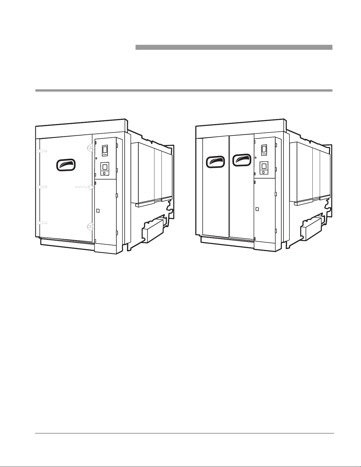
Figure 1–1. 2100 SERIES WASHERS
A03579-F
MANUAL DOOR POWERED DOOR
2100 series units are automatic, heavy duty, multi-cycle, single chamber,
floor loading, hydro-spray washers. These units are designed to efficiently
and thoroughly clean, sanitize and dry cages, racks, racked utensils, and
bottles used in research animal care facilities.
Both powered single or double door pass-through units are available. Units
may be floor or pit mounted through one or two walls or installed free
standing. Left or right side service access and control panel locations are
available
A03579-A
61301603579 1–1
Page 20

General Description
Models and typical dimensions are listed in Table 1–1.
Table 1–1. 2100 SERIES WASHERS
MODEL CHAMBER
(in. [cm])
2110 46 W x 85 H x 93 L
[117 x 216 x 236]
2120 46 W x 85 H x 141 L
[117 x 216 x 358]
2130 46 W x 85 H x 189 L
[117 x 216 x 480]
2150 72 W x 85 H x 141 L
[183 x 216 x 358]
OVERALL
84 W x 105 H x 105 L
[213 x 267 x 267]
84 W x 105 H x 153 L
[213 x 267 x 389]
84 W x 105 H x 201 L
[213 x 267 x 511]
123 W x 105 H x 153 L
[312 x 267 x 389]
(in. [cm])
Routine operation consists of loading the chamber, closing the door, and
pressing START. The Washer then performs the processing cycle and
automatically shuts off when the cycle is complete. Following completion,
either the Unload End door (Double Door Pass-Through model only) or the
Load Door is opened and the load is removed.
Treatment solutions are delivered by means of an oscillating (back and forth
motion) manifold equipped with spray nozzles. Automatic dispensing of
detergent during the Wash phase is a standard feature.
Processing cycles are controlled by means of a Programmable Logic
Controller (PLC) equipped with a Touch Control Panel (TCP) or a LED
screen. Twelve cycle selections are possible. The user needs to select and
start an appropriate cycle.
Standard Features
1–2
A standard cycle consists of the following sequential phases: Prewash,
Wash 1, Wash 2, Rinse 1, Rinse 2, Rinse 3, and Exhaust. Any adjustments
to a cycle's phase timing are made at the control panel.
The washer may be installed in a pit (Pit-Mounted) or installed at floor level
(Floor Mounted Option). When installed in a pit, the floor of the wash
chamber is the same level as the room floor allowing direct loading and
unloading of carts. When installed at floor level, the floor of the chamber is
higher than the room floor; ramps are provided as standard equipment to
facilitate loading and unloading.
• Microcomputer Control System
• Twelve User Programmable Cycles
• Automatic Seven Phase Treatment Cycles
• Program Access Code Security
• Wash and Rinse Temperature Assurance
• Built-in Service Diagnostics
• Personnel Safety System
• Oscillating Jet Spray System
• Fully Draining Treatment Pump and Sump
• No Treatment Solution Carry Over
Page 21

• Automatic Sump Water Level Control
• Automatic Self-Cleaning Debris Filter
• Stainless Steel Steam Coil Heating
• Power Slide Telescoping Door(s)
• All Stainless Steel Construction
• Smooth Chamber Interior Construction
• Full Chamber Stainless Steel Floor Grating
• Insulated Chamber Construction
• Illuminated Chamber Interior
• Left or Right Service Side Installation
• Pit or Floor Mounting
Series 2100 Washers
Optional Features
• Printer
• LED Controls
• Electro-Mechanical Controls
• RS232 or RS485 Port for Data Download
• Air Dry System
• Double Door Pass-Through
• Double Door Interlocks for Manual Doors
• Manual Swing-Out, Side Hinged Doors
• Stainless Steel Treatment Components
• Alkaline or Acid Wash Agent Saver System
• Cold Water Prewash Treatment
• Non-Recirculated Rinse Systems
• Water Supply Temperature Booster
• Automatic Agent Injection Systems
• Floor Jet Spray Header
• Automatic Manifold Bottle/Utensil Rack Coupling
• Center Header System
• Pan Washing
• Automatic Water Rack Flushing System
• Automatic Damper
• Exhaust Fan
• Vapor Removal Condenser
• Drain Discharge Cool-Down System
• Treatment Solution pH Neutralization
• Free-Standing Cabinet System
• Seismic Design
• Knocked Down Shipment
• Modem
• Modem Troubleshooting
• Pit Flush
Accessories
• Floor Loading
• Hydraulic Low Entry Loading Platform
• Cart Tilt Ramps
• Universal Cage and Pan Processing Rack
• Cage Processing Rack
• Pan Processing Racks
• Manifold Feeder Bottle Rack
• Cage Processing Rack for Central Header System
• Feeder Bottle Baskets
• Stainless Steel Pit Plates
61301603579 1–3
Page 22
General Description
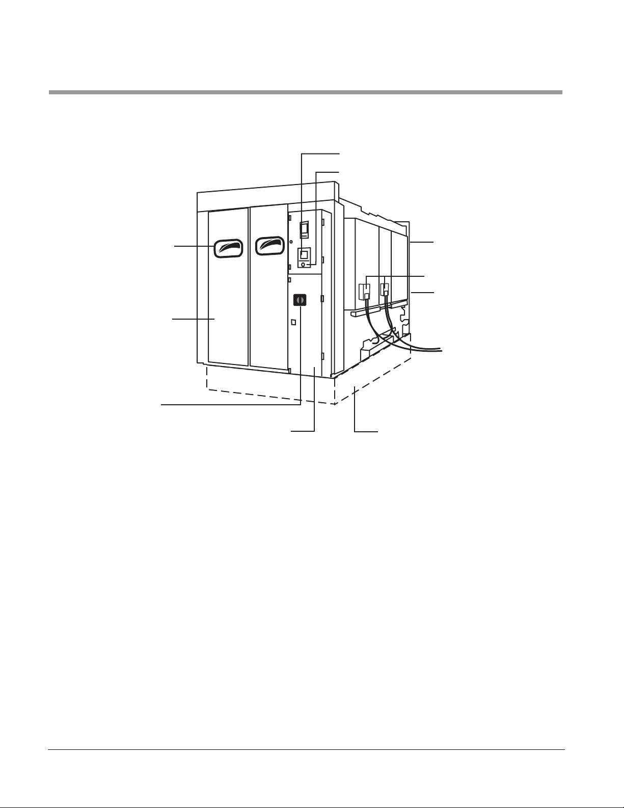
EXTERIOR COMPONENTS
Figure 1–2. EXTERNAL COMPONENTS
CONTROL PANEL
EMERGENCY STOP SWITCH
OBSERVATION
WINDOW
ELECTRICAL DISCONNECT SWITCH
Control Panel
LOAD END
DOOR
UNLOAD END
CONTROL PANEL
DISPENSERS
CONTROL
I ON
0 OFF
PIT
UNLOAD END
DOOR
BOX
Standard unit shown: pit mounted
Provides a pressure sensitive touch screen for the user that is connected to
a Programmable Logic Controller (PLC) located in the Control Box. Enables
the user to select, program, and monitor processing cycles.
EMERGENCY STOP Switch
Electrical Disconnect Switch
Doors
1–4
The EMERGENCY STOP Switch should be used to terminate all treatment
functions and activate the audible alarms.
Rotate the Electrical Disconnect Switch to the:
• ON position to energize the washer.
• OFF position to de-energize the washer.
Provide access to the Washer chamber. Each door is equipped with an
Observation Window. Safety Latches are included on all Swing-out Door
models. Safety Latches are designed to release a closed door when a
moderate amount of physical force is applied against the surface of the door
from the inside.
Page 23

Series 2100 Washers
Door Closed Switches
Alarm (Not Shown)
Service Area (Not Shown)
Dispenser (Option)
Pit
Automatic Self-Cleaning Debris Filter (Not Shown)
Stops Washer operation if a Load or Unload End Door is opened during a
cycle. Prevents the start of washer operation if a door is not closed. Located
on the Load and Unload End Control Panels.
Sounds an audible alert when:
• A cycle is completed (Pulsing/Audible alarm).
• A cycle is aborted.
• A Safety Cable is pulled.
• The Programmable Logic Controller (PLC) detects processing
problems.
Contains piping, valves, pumps, control box, manifold drive motor, etc.
An optional Chemical Dispenser automatically pumps the required chemical
into the water solution held in the sump. The Dispenser is activated during
the wash phases of a processing cycle.
Supports the bottom structure of the washer within a drained enclosure,
thus enabling the Washer chamber to be situated at floor level for ease of
loading and unloading.
The output of the wash pump is provided with a self-cleaning debris filter
screen having perforations smaller than the spray jet orifices to prevent
plugged jets. The filter is attached to the Treatment Pump and is back
flushed by a ball valve operated by the control system. The filter screen can
be accessed without the use of tools.
A screen is provided at the input to the pump to prevent large debris from
entering the pumping system.
The automatic self-cleaning debris filter screen should be rinsed clean
weekly, removing any debris. See Table 4–1, “Maintenance Schedule—
Standard,” on page 1.
61301603579 1–5
Page 24

General Description
Figure 1–3. UNLOAD END CONTROL PANEL
EMERGENCY CABLE
RESET SYSTEM
IN PROGRESS
COMPLETE
CYCLE
OPEN DOOR
EMERGENCY CABLE RESET SYSTEM
IN PROGRESS Indicator
COMPLETE CYCLE Indicator
OPEN DOOR Switch (Option)
EMERGENCY
STOP
After the Personnel Safety System has been used, press the EMERGENCY
CABLE RESET SYSTEM shaft to reset the switch. Turn the power off/on to
reset the washer. For more information, see “PERSONNEL SAFETY
SYSTEM” on page -xiv. The EMERGENCY CABLE RESET SYSTEM
Switch is located on the Unload End Control Panel.
Displays a red light for the duration of an ongoing processing cycle. The IN
PROGRESS Indicator is located at the Unload End of the Washer. Displays
the operational status of the unit at the Unload End.
Displays a green light whenever the Electrical Disconnect Switch is turned
ON, as long as a cycle is not operating. The light turns off at the start of a
processing cycle. When the cycle ends, the light comes back on. The
CYCLE COMPLETE Indicator is located at the Unload End of the Washer.
Displays the operational status of the unit at the Unload End.
Press and release the OPEN DOOR Switch to open the power door when
the washer is not in a cycle. Located on the Unload End. This option is
available on power door models only.
EMERGENCY STOP Switches (Load and Unload End)
1–6
Pressing the EMERGENCY STOP switch terminates all functions of the
washer and sounds the alarm.
Page 25
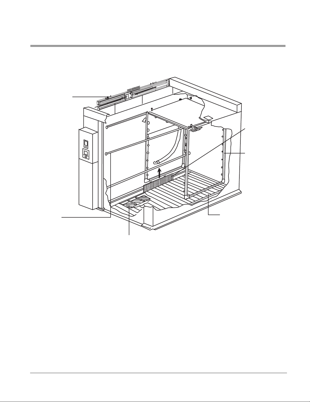
INTERIOR COMPONENTS
SPRAY MANIFOLD
DRIVE ASSEMBLY
Series 2100 Washers
Figure 1–4. CHAMBER COMPONENTS
PRIMARY
DEBRIS FILTER
SPRAY MANIFOLD
HAND
RAIL
Spray Manifold
Spray Manifold Drive Assembly
Hand Rail
FLOOR GRATES
SUMP
a03579C
Delivers the various wash and rinse spray treatments to the load during a
processing cycle. Vertical and horizontal sections, fitted with spray nozzles,
make up the complete assembly.
Moves the Spray Manifold back and forth along the length of the chamber
during a processing cycle.
Functions as a restraint to keep items, such as utensil carts, from being
improperly positioned. Four rails are provided, two on each side of the
chamber.
61301603579 1–7
Page 26

General Description
Floor Grates
Sump
Exhaust Damper (Not Shown)
The grates are removable in sections; the number of sections depending on
the length of the chamber. In the Inclined Floor Grating option, the floor
grates are slightly pitched to assist in the draining of pans and racks.
Holds the supply of solution (wash and rinse) that is pumped to the Spray
Manifold during a processing cycle. During processing, it collects all
drainage for recirculation. A steam heating coil installed in the sump
maintains the temperature of the wash solution and other treatment
solutions - if specified. Drain screens cover the inlet to the extended sump to
prevent large particles of foreign matter from entering.
Opens during the Exhaust phase of a wash cycle to permit residual vapors
to escape from the chamber. Partially closed during the wash and rinse
phases of the wash cycle.
1–8
Page 27
OPTIONS
Series 2100 Washers
The 2100 Washer may be equipped with the following options:
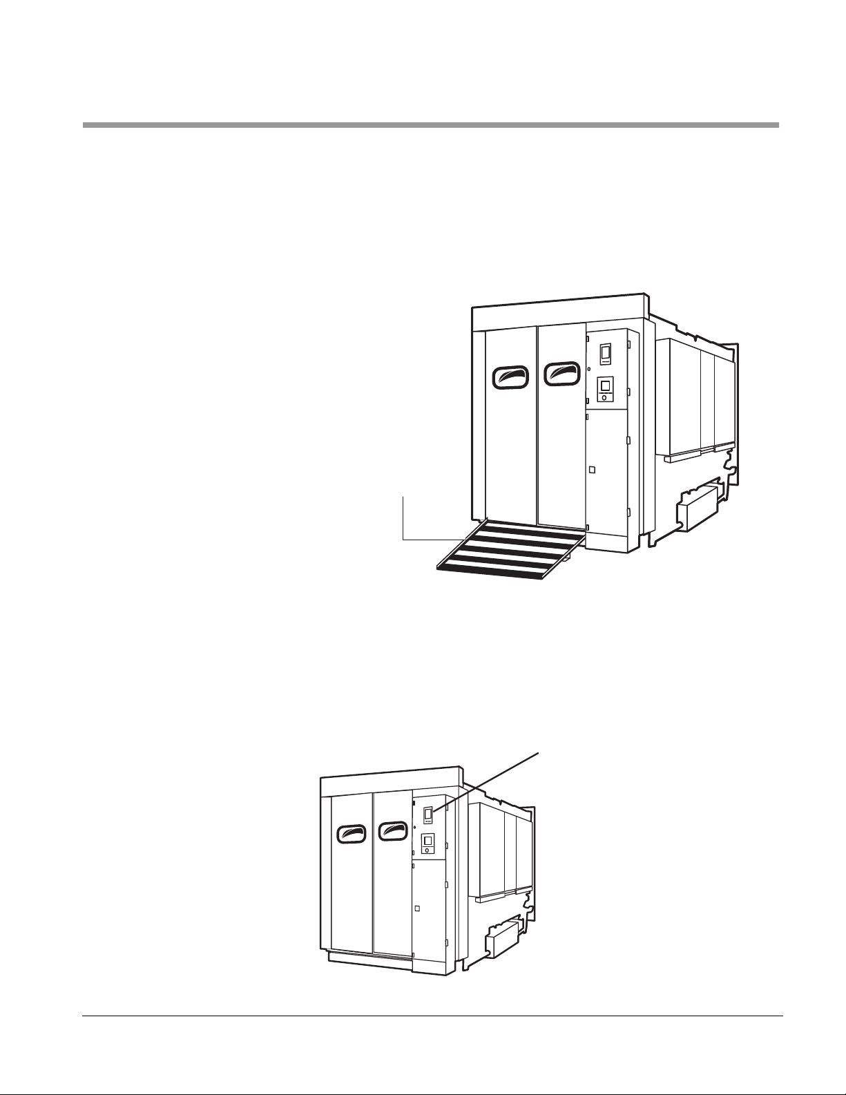
Floor Mounting
Washer may be installed at floor level if a shallow pit is undesirable or
impractical. The result is a chamber floor that is higher than the surrounding
room floor. Door Ramps are provided with Floor Mounted units to facilitate
loading and unloading.
Figure 1–5. FLOOR MOUNTING (Option)
Floor Loading Ramp
A03579-D
Recorder/Printer
Issues a printed record of all pertinent cycle data, including treatment
functions, temperature, time, and date. A Take-Up Reel is provided to
retrieve and wind the print-out onto a spool. See “Printer” on page 7-4 for
additional information.
Figure 1–6. RECORDER/PRINTER (Option)
RECORDER/PRINTER
A03579-E
61301603579 1–9
Page 28

General Description
ACCESSORIES
The following is a list of Accessories. Below the list is a description of each.
• Floor Loading Ramp
• Hydraulic Low Entry Loading Platform
• Cart Tilt Ramp
• Universal Cage and Pan Processing Rack
• Cage Processing Rack
• Pan Processing Rack
• Manifold Feeder Bottle Rack
• Cage Processing Rack For Central Header System
• Feeder Bottle Baskets
• Stainless Steel Pit Plates
Floor Loading Ramp
Hydraulic Low Entry Loading Platform
Cart Tilt Ramp
Universal Cage and Pan Processing Rack
Cage Processing Rack
Pan Processing Rack
A stainless steel ramp(s), with a non-skid surface, is provided to permit
loading and unloading of floor mounted units.
A stainless steel hydraulic powered lifting platform with a non-skid loading
surface is provided to aid in the loading and/or unloading of the washer
chamber. The cart or rack is rolled onto the platform. The user operates the
platform raising the cart/rack to the level of the chamber floor. The user rolls
the rack into the wash chamber for processing. This lifting system eliminates
the hazard of pushing or pulling heavy racks up a fixed loading ramp. A
separate 30 AMP electrical connection is required.
A stainless steel ramp is installed inside the chamber to incline the carts to
permit the most effective draining and drying.
A stainless steel rack with an automatic pivoting counterweight is provided
to accommodate cages from 5'' to 8'' in height and pans with a maximum
depth of 3''. The rack is transported by casters and roller bearings. Rack
capacity varies, depending on the model.
A stainless steel rack is provided to process cages from 5'' to 8'' in height.
The rack is transported by casters and roller bearings. Rack capacity varies,
depending on the model.
A stainless steel rack to process pans with a maximum depth of 3''. The rack
is 32'' wide, 70'' high, and 72'' long and is transported by casters and roller
bearings. Rack capacity: Rabbit Pans - 30.
Manifold Feeder Bottle Rack
Cage Processing Rack For Central Header System
1–10
A stainless steel manifold, multi-jet type rack is provided for processing
feeder bottles. The 8, 16, and 32 oz. bottles can be processed along with
the stainless steel baskets used to transport the bottles. The rack is
supported by casters and roller bearings and couples to the manifold rack
coupling system. The racks can be configured for two, four, or six basket
capacity.
A stainless steel cage rack is provided for processing large volumes of
standard mouse cage or rat cages. (Note: Rack to be set up for either
mouse or rat cages). The rack is supported by casters and roller bearings
Page 29

Series 2100 Washers
and couples to the manifold rack coupling system. Rack capacity: Mouse
Cages - 200, or Rat Cages - 96 or Rabbit Pans - 80.
Feeder Bottle Baskets
Stainless Steel Pit Plates
Stainless steel bottle baskets are provided for processing 8, 16, or 32 oz.
bottles. The baskets are configured either to a 4x6 or a 5x5 bottle pattern.
Provided are stainless steel pit plates to be installed in the pit (by others) in
lieu of cold rolled steel. Reference pit drawing.
61301603579 1–11
Page 30

General Description
PROCESSING CYCLE DESCRIPTION
A 2100 washer runs the following processing cycle.
Automatic Seven Phase Treatment Cycle
Operation
Treatment Schedule
The standard treatment cycle consists of a Prewash, Wash 1, Wash 2,
Rinse 1, Rinse 2, Rinse 3, and an Exhaust. All cycle phases are adjustable
from 0 - 60 minutes. All wash and rinse treatments are recirculated under
pump pressure. The cycle, once activated, is completely automatic.
Additional cycle treatment phases are available.
At the start of the processing period, the user places the load to be cleaned
in the chamber, closes the door, selects the desired cycle and presses the
cycle start switch. The washer automatically proceeds through the
treatment process and alerts the user when the process is complete. The
user then opens the chamber door and removes the cleaned load.
PREWASH
Hot water, from house supply, fills the sump, or water remaining in the sump
from Rinse 3 of the previous cycle, is recirculated through the jet spray
system under pump pressure and pumped to drain upon completion. Phase
time and temperature is user programmable, from 0-60 minutes and 120°-
190°F respectively.
WASH 1
Hot water, from house supply, fills the sump and wash agent is automatically
added. The treatment solution is recirculated through the jet spray system,
under pump pressure, and is pumped to drain upon completion. Phase time
and temperature is user programmable, from 0-60 minutes and 120°-190°F
respectively.
NOTE
Agent Saver Option: If the agent saver option is selected, the hot agent
solution from the agent solution reservoir fills the sump and is recirculated through the jet spray system. At the end of the treatment, the
agent solution is returned to the agent solution reservoir.
Soak Option: A subsequent soak period may be programmed from 060 minutes, to permit the acid solution to work on the load before proceeding to the second wash and/or rinse treatments. A soak option can
only be activated after an acid wash.
When selected, the soak always follows the “Acid” agent wash.
WASH 2
Hot water, from house supply, fills the sump and wash agent is automatically
added. The treatment solution is recirculated through the jet spray system,
under pump pressure, and is pumped to drain upon completion. Phase time
and temperature is user programmable, from 0-60 minutes and 120°-190°F
respectively.
Agent Saver Option: If the agent saver option is selected, the hot agent
solution from the agent solution reservoir fills the sump and is recircu-
1–12
Page 31

Series 2100 Washers
lated through the jet spray system. At the end of the treatment, the
agent solution is returned to the agent solution reservoir.
Soak Option: A subsequent soak period may be programmed from 060 minutes, to permit the acid solution to work on the load before proceeding to the rinse treatments. A soak option can only be activated
after an acid wash.
NOTE
When selected, the soak always follows the “Acid” agent wash.
RINSE 1
Hot water, from house supply, fills the sump and is recirculated through the
jet spray system under pump pressure and pumped to drain upon
completion. Phase time and temperature is user programmable, from 0-60
minutes and 120°-190°F respectively.
RINSE 2
Hot water, from house supply, fills the sump and is recirculated through the
jet spray system under pump pressure and pumped to drain upon
completion. Phase time and temperature is user programmable, from 0-60
minutes and 120°-190°F respectively.
RINSE 3
Hot water, from house supply, fills the sump and is recirculated through the
jet spray system under pump pressure and pumped to drain upon
completion or saved in the sump to be used for the prewash phase of the
next cycle. Phase time and temperature is user programmable, from 0-60
minutes and 120°-190°F respectively.
Non-Recirculated Option: Hot water, from house supply, under house
pressure is sprayed directly through a separate jet system. Phase time
is user programmable from 0-60 minutes.
EXHAUST or VAPOR REMOVAL
Unit stands idle for a sufficient period of time for the facility vent system to
remove vapor from within the chamber. Phase time is user programmable
from 0-60 minutes.
Air Dry System Option: During the vapor removal phase, the air dry
system consists of a forced ambient or heated air manifold to blow residue water off the cages, pans, and racks. Phase time is user programmable from 0-60 minutes.
TEMPERATURE GUARANTEE SYSTEM:
All phases of the wash cycle except Soak and Exhaust have the option to
select a Temperature Guarantee Mode. When selected, this causes the unit
to fill and spray water normally for that phase, without allowing the main
timer to start counting down until the setpoint temperature has been
attained. If at any time the sump temperature should fall below the setpoint,
the main timer stops until the temperature exceeds the setpoint. Failure to
do so in a set period of time generates a “too long to heat” alarm.
61301603579 1–13
Page 32

General Description
1–14
Page 33

INTRODUCTION
Section 2 The Control Panel
The Control Panel on this Washer provides the user with an interface linked
to the Programmable Logic Controller (PLC) located in the Control Box.
Using the Control Panel, the user is able to do:
• Select a processing cycle.
• Program the cycle phase timing.
• Program the cycle phase temperature.
• Start a processing cycle.
• Monitor the status of an ongoing cycle.
• Manually drain the washer's sump.
In addition to the above, supervisory personnel are able to:
• Access load counters and time display
• Protect cycle programming
Your washer has one of the following control panels:
• TOUCH CONTROL PANEL (TCP),
• LED CONTROL PANEL, or
• ELECTRO-MECHANICAL CONTROL PANEL
Information on each control panel follows.
61301603579 2–1
Page 34

The Control Panel
TOUCH CONTROL PANEL (TCP)
Control Screens
SERIAL NUMBER: 2100-XX-XXXX
CUSTOMER'S FACILITY,
PUSH TO ACTIVATE CONTROL SYSTEM
GETINGE CASTLE
MODEL 2100
CITY, STATE
The following pages illustrate the available Control Screens. To advance
from screen to screen, note that each illustrated screen below contains a
gray area. Press the prompt on the screen, as it is highlighted on the
illustration, and the next screen will display. Programming a cycle should not
be accomplished from this section of the user manual. See “Cycle
Programming” on page 2-12.
Figure 2–1. MACHINE/CUSTOMER IDENTIFICATION SCREEN
Identifies Getinge/Castle Inc. as the
Equipment Manufacturer.
The Equipment Model Number.
The Equipment's Serial Number
(reference when calling for service).
Identifies the Equipment Owner.
Press this prompt to access the "SELECT CYCLE"
screen and continue operation.
2–2
Page 35

LOAD UNIT – SELECT CYCLE – REVIEW
CYCLE
2
CYCLE
CYCLE
3
7
CYCLE
CYCLE
1
5
CYCLE
6
Figure 2–2. CYCLE SELECTION SCREEN
CYCLE
4
CYCLE
8
Press the prompt of the desired cycle of operation.
Series 2100 Washers
CYCLE
9
LOAD DOOR
MANUAL
MODE
CYCLE
10
EVENT
PRINT OFF
CYCLE
11
UNLOAD DOOR
PRINT
CYCLE
CYCLE
12
REVIEW
CYCLE
Manual Doors: Prompts are "read only" and not used as touch
cells. When the Load Door is open, "LOAD DOOR" will be back-lit
red in color. When the Load Door is closed, "LOAD DOOR" will be
back-lit blue in color. Note that "UNLOAD DOOR" will be available
only on washers equipped with this option.
Power Door(s): When the washer is equipped with the power
door(s) option the "LOAD DOOR" and "UNLOAD DOOR" area on
the control panel is a pressure sensitive touch cell.
After the user has selected a cycle, this prompt must be pressed
to review the cycle and display the next screen.
Pressing this prompt will allow the printer to print the cycle
parameters.
When this prompt displays "EVENT PRINT ON", the operating
cycle will be printed.
Pressing this prompt places controls in "MANUAL MODE" to
test individual components.
61301603579 2–3
Page 36

The Control Panel
Figure 2–3. REVIEW PROGRAMMED PHASES SCREEN
Describes the current cycle selected.
CYCLE 1
PREWASH
RINSE
1
REVIEW AND START OR PROGRAM CYCLE
MAIN
MENU
WASH
1
RINSE
2
START
CYCLE
REVIEW PHASES
WASH
2
RINSE
3
PROGRAM
CYCLE
Describes the current control screen display.
SOAK
EXHAUST
PRINT
CYCLE
Illuminated prompts indicate phases
programmed to operate in this cycle.
Displays available options for this control
screen.
Pressing this prompt will allow user to change
cycle parameters if password is keyed in to unlock.
Pressing this prompt will print selected cycle
parameters.
Depress to start selected cycle.
Depress prompt to return to main menu.
Figure 2–4. PASSWORD SCREEN
Press prompt to enter password.
Unlocks user program.
2–4
CYCLE PROGRAM MODE
ENTER
PASSWORD
UNLOCKED
PROGRAM
CYCLE
CHANGE
PASSWORD
PRESS TO
CHANGE P/W
MAIN
MENU
SERVICE
PASSWORD
LOCKED
ADJUST
CALENDAR
CLOCK
Prompt is used for changing the user's password.
Prompt is for the Authorized Sevice Technician.
Press prompt to change password for the user program.
Prompts are "read only", showing the status of
program access ("LOCKED" or "UNLOCKED").
Prompt is used in setting the time and date.
Press prompt to go to "MAIN MENU."
When program is unlocked, prompt will allow
access to the programming screens.
Page 37

Figure 2–5. PASSWORD SCREEN
Series 2100 Washers
CURRENT VALUE
1
4
7
+
/–
PASSWORD
2
5
8
0
UNLOCKING PASSWORD
1. Enter Password.
MAXIMUM >>>32000
MINIMUM >>> 1
3
6
9
–
B/S
E
N
T
E
R
D
O
N
E
90
2. Press "ENTER".
3. Press "DONE".
90
New value must be above minimum and below maximum.
4. Screen will revert back to "PROGRAM CYCLE" screen.
Screen "UNLOCKED" displays.
5. Press "PROGRAM CYCLE".
6. Program is now accessible to change parameters.
Figure 2–6. PROGRAM CYCLE
CYCLE PROGRAM MODE
ENTER
PASSWORD
UNLOCKED
PROGRAM
CYCLE
CHANGE
PASSWORD
PRESS TO
CHANGE P/W
MAIN
MENU
SERVICE
PASSWORD
LOCKED
ADJUST
CALENDAR
CLOCK
Press prompt to enter password.
Unlocks user program.
Prompt is used for changing the user's password.
Prompt is for the Authorized Sevice Technician.
Press prompt to change password for the user program.
Prompts are "read only", showing the status of
program access ("LOCKED" or "UNLOCKED").
Prompt is used in setting the time and date.
Press prompt to go to "MAIN MENU."
When program is unlocked, prompt will allow
access to the programming screens.
61301603579 2–5
Page 38

The Control Panel
Figure 2–7. PROGRAM PREWASH SCREEN
CYCLE 1
PROGRAM PREWASH MENU
PREWASH ON
TIMER
60
TEMP
120
GUARANTEE
OFF
NEXT
PHASE
Displays the current cycle number.
Displays the phase of cycle to be programmed.
Displays status of phase. Press prompt to toggle "OFF".
Displays length of time the phase will be activated in seconds.
Displays the status of temperature guarantee.
Press prompt to change status to "TEMP. GUARANTEE".
Displays the programmed temperature of the sump.
Press prompt and enter new parameters.
Pressing this prompt will advance the menu to the next
phase screen.
2–6
Page 39

Figure 2–8. PROGRAM WASH #1 SCREEN
Series 2100 Washers
PROGRAM WASH 1 MENU
TIMER
300
SUMP TEMP
165
CYCLE
AGENT WASH #1 OFF
AGENT SELECTION
ALKALINE AGENT – DRAIN
1
Figure 2–9. PROGRAM WASH #2 SCREEN
GUARANTEE
OFF
NEXT
PHASE
Displays the current cycle.
Displays the phase of cycle to be programmed.
Displays status of phase. Press prompt to toggle "ON".
Displays length of time phase will be activated.
Displays status of temperature guarantee.
Press the prompt to change the status.
"AGENT SELECTION" prompt allows the programming of
agent washes, alkaline or acid, to be saved or drained
at the end of the phase, if Agent Saver Option is purchased.
Press the prompt to advance menu to the next phase screen.
Displays the current temperature parameter of the
sump solution. Press the prompt to allow a new parameter
to be entered.
PROGRAM WASH 2 MENU
TIMER
300
SUMP TEMP
165
CYCLE 1
AGENT WASH #2 ON
AGENT SELECTION
ACID AGENT DRAIN
GUARANTEE
OFF
NEXT
PHASE
Displays the current cycle.
Displays the phase of cycle to be programmed.
Displays status of phase. Press prompt to toggle "ON".
Displays length of time phase will be activated.
Displays the status of temperature guarantee.
Press the prompt to change the status.
"AGENT SELECTION" prompt allows the programming of
agent washes, alkaline or acid, to be saved or drained
at the end of the phase, if Agent Saver Option is purchased.
Press the prompt to advance the menu to the next
phase screen.
Displays the current temperature parameter of the
sump solution. Press the prompt to allow a new parameter
to be entered.
61301603579 2–7
Page 40

The Control Panel
Figure 2–10. PROGRAM SOAK SCREEN
CYCLE 1
PROGRAM SOAK MENU
SOAK ON
TIMER
120
NEXT
PHASE
Figure 2–11. PROGRAM RINSE #1 SCREEN
CYCLE 1
Displays the current cycle.
Displays the phase of the cycle to be programmed.
Displays the status of the phase. Press prompt to toggle "ON".
Displays the length of time the phase will be activated.
Press this prompt to advance the menu to the next
phase screen.
Displays the current cycle.
PROGRAM RINSE 1 MENU
RINSE #1 ON
TIMER
120
SUMP TEMP
185
TEMP.
GUARANTEED
PHASE
Displays the phase of the cycle to be programmed.
Displays status of the phase. Press prompt to toggle "ON".
Displays length of time the phase will be activated.
Displays status of temperature guarantee.
Press prompt to change status to "GUARANTEE OFF".
Displays the programmed parameter of the sump solution.
Press the prompt to allow a new parameter to be entered.
NEXT
Press this prompt to advance the menu to the next
phase screen.
2–8
Page 41

Figure 2–12. PROGRAM RINSE #2 SCREEN
Series 2100 Washers
CYCLE
1
PROGRAM RINSE 2 MENU
RINSE #2 OFF
TIMER
0
SUMP TEMP
0
GUARANTEE
OFF
PHASE
Figure 2–13. PROGRAM RINSE #3 SCREEN
Displays the current cycle.
Displays the phase of cycle to be programmed.
Displays status of the phase. Press prompt to toggle "ON".
Displays the length of time the phase will be activated.
Displays status of the temperature guarantee.
Press prompt to change status to "TEMP. GUARANTEE".
Displays the programmed parameter of the sump solution.
Press the prompt to allow a new parameter to be entered.
NEXT
Press the prompt to advance the menu to the next
phase screen.
CYCLE
PROGRAM RINSE 3 MENU
RINSE #3 OFF
TIMER TEMP
60
MAIN
MENU
SUMP TEMP
120
1
GUARANTEE
Displays the current cycle.
Displays the phase of cycle to be programmed.
Displays status of the phase. Press prompt to toggle "ON".
Displays length of time the phase will be activated.
Displays status of the temperature guarantee.
Press prompt to change status to "TEMP. GUARANTEE".
Displays the programmed parameter of the sump solution.
Press the prompt to allow new a parameter to be entered.
Press this prompt to return to the "MAIN MENU".
61301603579 2–9
Page 42

The Control Panel
Figure 2–14. CALENDAR CLOCK
This prompt is "read only" and displays current month.
CALENDAR CLOCK - ENTER NEW VALUES
THEN PRESS CHANGE PB TO CHANGE VALUES
PLC MONTH
NEW MONTH
PLC HOUR
NEW HOUR NEW MINUTE
PLC DAY
NEW DAY NEW YEAR
PLC MINUTE
PLC YEAR
SAVE
CHANGES
BACK TO
ACCESS
SCREEN
Displays the current screen description.
This prompt is "read only" and displays the current Day.
This prompt is "read only" and displays the current Year.
This prompt is used for changing the Day. Press the prompt
and enter the desired Day.
This prompt is used for changing the Year. Press the prompt
and enter the desired Year.
This prompt is used for changing the Month. Press the
prompt and enter the desired Month.
Press this prompt to take user back to the access screen.
Press this prompt to save all of the settings in the
"CALENDAR CLOCK" screen.
This prompt is "read only" and displays the current minute.
This prompt is "read only" and displays the current hour.
This prompt is used for changing the Minute.
Press the prompt and enter the desired Minute.
This prompt is used for changing the Hour.
Press the prompt and enter the desired Hour.
2–10
ACCESSING THE CALENDAR CLOCK SCREEN
1. From the CYCLE SELECTION screen, press “REVIEW
CYCLE”.
2. From the REVIEWED PROGRAMMED PHASES screen,
press, “PROGRAM CYCLE”.
3. On the Password screen, press “ADJUST CALENDAR
CLOCK”.
Page 43

Series 2100 Washers
Manual Mode #1 Cycle Screen Description
MANUAL MENU #1
TREATMENT
PUMP OFF
ALKALINE
DETERGENT
SUMP HEAT DAMPER
JET VALVE
OPEN
ACID
DETERGENT
MAIN
MENU
Figure 2–15. MANUAL MODE EXAMPLE
SELECT DESIRED
FUNCTION/ABORT TO QUIT
DRAIN
VALV E
ACID
NEUTRALIZE
DRAIN
COOLING
ANSWER
ALARM
HEADER
DRIVE
SUMP FILL
ABORT
Press any prompt to activate the selected components.
Press the prompt again to stop selected component or
"ABORT" to stop all of the components activated.
All safeties are intact in the manual mode. The wash or
rinse pumps will not operate if there is not enough
water in the sump. The Wash pump will operate for 60
seconds without water.
Sump fill will not activate if sump is full.
Sump fill will stop when sump is full.
ACCESSING THE MANUAL MODE SCREEN
1. From the CUSTOMER IDENTIFICATION screen, press
“PUSH TO ACTIVATE CONTROL SYSTEM”.
2. From the CYCLE SELECTION screen, press “MANUAL
MODE”.
61301603579 2–11
Page 44

The Control Panel
Cycle Programming
Example: Programming a Sample Cycle
PHASE
TIME
(seconds)
The following is a SAMPLE cycle along with detailed instructions on how to
program the cycle for your reference.
TEMPERATURE
(°F)
TEMPERATURE
GUARANTEE
Sample Cycle 1—Touch Control Panel
Prewash 60 120 Off
Wash 1 300 165 Off
Soak none
Wash 2 300 165 Off
Soak none
Rinse 1 120 185 On
Rinse 2 None Off Off
SAVE/DUMP TO
DRAIN
AGENT
Alkaline Save
Acid Drain
TANK
TEMP (°F)
Rinse 3 60 180 Off
LOAD UNIT – SELECT CYCLE – REVIEW
CYCLE 1
CYCLE 5
CYCLE 9 CYCLE 10 CYCLE 11 CYCLE 12
LOAD DOOR
MANUAL
MODE
CYCLE 2 CYCLE 3 CYCLE 4
CYCLE 6
EVENT
PRINT OFF
CYCLE 7
UNLOAD DOOR
PRINT
CYCLE
CYCLE 8
REVIEW
CYCLE
CYCLE SELECTION SCREEN:
Programmer should-
Ø Press the “CYCLE 1" prompt.
Ø Press the “REVIEW CYCLE” prompt.
2–12
Page 45

CYCLE SELECTION SCREEN:
Programmer should-
Series 2100 Washers
CYCLE 1
PREWASH
RINSE
1
WASH
1
RINSE
2
REVIEW PHASES
WASH
2
RINSE
3
SOAK
EXHAUST
REVIEW AND START OR PROGRAM CYCLE
MAIN
MENU
START
CYCLE
PROGRAM
CYCLE
PRINT
CYCLE
CYCLE PROGRAM MODE
ENTER
PASSWORD
CHANGE
PASSWORD
SERVICE
PASSWORD
Ø Press the “PROGRAM CYCLE” prompt.
CYCLE SELECTION SCREEN:
Programmer should-
Ø Press the “ENTER PASSWORD” prompt.
Ø Enter the correct password “12345”.
Ø Press the “ENTER” prompt.
Ø Press the “DONE” prompt. This unlocks the system.
Ø Press the “PROGRAM CYCLE” prompt.
UNLOCKED
PROGRAM
CYCLE
PRESS TO
CHANGE P/W
MAIN
MENU
LOCKED
ADJUST
CALENDAR
CLOCK
61301603579 2–13
Page 46

The Control Panel
CYCLE SELECTION SCREEN:
Programmer should-
CYCLE 1
PROGRAM PREWASH MENU
PREWASH ON
TIMER TEMP
60
120
GUARANTEE
OFF
Ø If “PREWASH OFF” is displayed, press “PREWASH
OFF” prompt to change the phase to “PREWASH ON”.
Ø Press the “TIMER” prompt and set the phase time to 60
seconds.
Ø Press the “TEMP” prompt and set the temperature to
120°F.
Ø If “TEMP. GUARANTEE” is displayed, press “TEMP.
GUARANTEE” to change the status to “GUARANTEE
OFF”.
Ø Press the “NEXT PHASE” prompt.
NEXT
PHASE
CYCLE SELECTION SCREEN:
Programmer should-
CYCLE
PROGRAM WASH 1 MENU
AGENT WASH #1 ON
TIMER
300
SUMP TEMP
165
AGENT SELECTION
ALKALINE AGENT – SAVE
1
GUARANTEE
OFF
NEXT
PHASE
Ø If “AGENT WASH #1 OFF” is displayed, press “AGENT
WASH #1 OFF” prompt to change the phase to “AGENT
WASH #1 ON”.
Ø Press the “TIMER” prompt and set phase time to 300
seconds.
Ø Press the “SUMP TEMP” prompt and set the phase temp
to 165°F.
Ø If “TEMP. GUARANTEE” is displayed, press “TEMP.
GUARANTEE” prompt and change the phase to “GUAR-
ANTEE OFF”.
Ø Press the “AGENT SELECTION” prompt to select
“ALKALINE AGENT – SAVE”.
Ø Press the “NEXT PHASE” prompt to continue.
2–14
Page 47

CYCLE SELECTION SCREEN:
Programmer should-
Series 2100 Washers
PROGRAM WASH 2 MENU
TIMER
300
SUMP TEMP
165
CYCLE
AGENT WASH #2 ON
AGENT SELECTION
ACID AGENT – DRAIN
1
GUARANTEE
OFF
NEXT
PHASE
Ø If “AGENT WASH #2 OFF” is displayed, press the
“AGENT WASH #2 OFF” prompt to change the phase to
“AGENT WASH #2 ON”.
Ø Press the “TIMER” prompt and set the phase time to 300
seconds.
Ø Press “SUMP TEMP” and set the phase temperature to
165°F.
Ø If “TEMP. GUARANTEE” is displayed, press “TEMP.
GUARANTEE” prompt to change the phase to “GUARAN-
TEE OFF”.
Ø Press the “AGENT SELECTION” prompt to select “ACID
AGENT – DRAIN”.
Ø Press the “NEXT PHASE” prompt to continue.
CYCLE SELECTION SCREEN:
Programmer should-
CYCLE
1
PROGRAM RINSE 1 MENU
RINSE #1 ON
TIMER
120
SUMP TEMP
185
TEMP.
GUARANTEED
PHASE
Ø If “RINSE #1 OFF” is displayed, press the “RINSE #1
OFF” prompt to change the phase to “RINSE #1 ON”.
Ø Press the “TIMER” prompt and set the phase time to 120
seconds.
Ø Press the “SUMP TEMP.” prompt and set the phase
temp to 185°F.
Ø If “GUARANTEE OFF” is displayed, press “GUARAN-
TEE OFF” prompt to change the phase to “TEMP. GUARANTEE”.
Ø Press the “NEXT PHASE” prompt to continue.
NEXT
61301603579 2–15
Page 48

The Control Panel
CYCLE
PROGRAM RINSE 2 MENU
RINSE #2 OFF
1
CYCLE SELECTION SCREEN:
Programmer should-
Ø If “RINSE #2 ON” is displayed, press the “RINSE #2 ON”
prompt the phase to “RINSE #2 OFF”.
Ø Press the “Next Phase” prompt to continue.
TIMER
0
SUMP TEMP
0
GUARANTEE
OFF
NEXT
PHASE
CYCLE 1
PROGRAM RINSE 3 MENU
RINSE #3 ON
TIMER GUARANTEE
60
SUMP TEMP
180
OFF
CYCLE SELECTION SCREEN:
Programmer should-
Ø If “RINSE #3 OFF” is displayed, press the “RINSE #3
OFF” prompt to change the phase to “RINSE #3 ON”.
Ø Press the “TIMER” prompt and set the phase time to 60
seconds.
Ø Press the “SUMP TEMP” prompt and set the phase temp
to 180°F.
Ø If “TEMP GUARANTEE” is displayed, press the “TEMP
GUARANTEE” prompt to change the phase to “GUARAN-
TEE OFF”.
Ø Press the “MAIN MENU” prompt to continue.
MENU
2–16
MAIN
Page 49

LED CONTROL PANEL
Key Locations
SECTION 1
STATUS LIGHTS
Series 2100 Washers
SECTION 2
FUNCTION KEYS
SECTION 3
DATA ENTRY KEYS
The above screen has been separated into 3 sections
• Section 1 Status Lights
• Section 2 Function Keys
• Section 3 Data Entry Keys
Information on each section follows.
61301603579 2–17
Page 50

The Control Panel
#1 status light will be on when left and right cables have not been pulled
#2 status light will be on when left and right cables are within adjustment
Section 1— Status lights
#3 status light will be on when load door is in the closed position
#4 status light will be on when unload door is in the closed position
#5 status light will be on when alkaline tank is full
Cable
OK
Cable
OK
Load
Door
Unload
Door
Tank
Full
Tank at
set point
Sump
Full
#8 status light NOT USED
#7 status light will be on when sump is full of water
#6 status light will be on when alkaline tank is at programmed temperature
2–18
Page 51

Section 2— Function keys
Series 2100 Washers
START
ABORT
MANUAL
SELECT
CYCLE
ENTER
SERVICE
MODE
SILENCE
ALARM
REVIEW
CYCLE
EXIT
SERVICE
MODE
EVENT
PRINT
ON/OFF
LOAD
DOOR
FUNCTION KEY FUNCTION
START Start the selected cycle.
ABORT Stop all functions of washer.
MANUAL Enter the manual mode.
LOAD DOOR Open or close load door.
PROGRAM
CYCLE
CYCLE
HOLD
PRINT
CYCLE
SELECT CYCLE Access cycle selection screen.
ENTER SERVICE
MODE
SILENCE ALARM Silence audible alarm.
REVIEW CYCLE Review selected cycle.
EXIT SERVICE MODE Exit service mode and return to stand-by
EVENT PRINT
ON/OFF
PROGRAM CYCLE Access selected cycles program for
CYCLE HOLD Stop cycle timer in current phase of
PRINT CYCLE Print parameters of selected cycle.
For authorized service technician only.
screen.
Record live readings of selected cycle as
load is being processed.
parameter changes.
operation.
61301603579 2–19
Page 52

The Control Panel
Section 3— Data Entry keys
LAST
MESSAGE
NEXT
MESSAGE
Used to review last screen
Used to review next
available screen
LAST
MESSAGE
NEXT
MESSAGE
PAG E
UP
PAG E
DOWN
PRINT
SCREEN
12
ALARM
4
SETUP
7
HELP
±
Key/Function
HELP
Not used
±
Used for the #2 or
to move cursor up
2
ACK
56
8
0
+
-
TOGGLE
3
9
.
CLEAR
DELETE
E
N
T
E
R
-
TOGGLE
Used for the #9
9
Used to activate components or deactivate compo-
.
nents in Manual Mode.
PAG E
UP
PAG E
DOWN
SETUP
Used to scroll to
previous page
Used to scroll to next page
Used for the #1
Used for the #4 or
to move cursor left
4
Used for the #7 or
place PLC into direct
7
MODEM contact
ALARM
ACK
+
Used for the #5
5
Used for the #8 or
to move cursor down
8
Used for the #0
0
Used for the #3
3
Used for the #6 or
to move cursor right
6
CLEAR
DELETE
E
N
T
E
R
Used to clear old
parameters
Not used
Used to enter new
parameter
2–20
Page 53

Series 2100 Washers
Control Sequences
START-UP
Energize the unit. The unit operates a diagnostic test. Once the
controller operates the test, the screen displays “Getinge Castle, Inc.”. The programmed unit is now ready to be used or programmed.
OPERATION
At the beginning of the processing period, the user activates
the unit for automatic operation. The unit automatically
advances to the “READY” state when the required operational
conditions are attained.
The operator places the load to be cleaned into the chamber,
closes the chamber door, selects the desired cycle, reviews the
cycle, and presses the “START” function key on the control
panel. The washer automatically proceeds through the treatment process and alerts the user when the process is complete. The user then opens the chamber door and removes the
cleaned load.
ALARM
If an alarm should sound at any time, follow the prompt on the
display screen and then press “Alarm Ack” on the keypad to
turn the sound off, and to return to the program.
HELP
A help screen is provided to assist the user.
61301603579 2–21
Page 54

The Control Panel
Processing Cycle Screen Description
Stand-by Screen
Cable
Message
Unload
Door
Tank
Tank at
Sump
Full
set point
Full
Load
Cable
Door
OK
OK
Alarm
Print
Run
Cycle Selection
START
ABORT
MANUAL
LOAD
DOOR
SELECT
CYCLE
ENTER
SERVICE
MODE
SILENCE
ALARM
REVIEW
CYCLE
EXIT
SERVICE
MODE
EVENT
PRINT
ON/OFF
PROGRAM
CYCLE
CYCLE
HOLD
PRINT
CYCLE
LAST
MESSAGE
NEXT
MESSAGE
PAG E
UP
PAG E
DOWN
PRINT
SCREEN
12
4
SETUP
7
HELP
±
ALARM
ACK
56
8
0
TOGGLE
+
CLEAR
3
DELETE
-
E
9
N
T
E
R
.
From the STAND-BY SCREEN the user can press the following
function keys:
1. “SELECT CYCLE” to select the desired cycle
2. “REVIEW CYCLE” to review parameters of selected cycle.
3. “MANUAL” to test functions of individual components.
4. “PROGRAM CYCLE” to modify the parameters of the
selected treatment cycle.
MTP MODEL 2110
CAGE, RACK & UTENSIL WASHER
2–22
From the STAND-BY SCREEN (shown above):
1. Press the “SELECT CYCLE” function key (screen shown
below).
MTP MODEL 2110
CAGE, RACK & UTENSIL WASHER
2. Press “Clear” on the keypad.
3. Enter the cycle number, ranging from “1”-”12”.
Page 55

4. Press “ENTER” on the keypad.
Series 2100 Washers
Review Cycle
REVIEW SCREEN #1.
PREWASH = ON
TEMP = 120 F
TIME = 60 SEC
GUAR = OFF
*
Pressing “Page Down”, user can view all parameters of the
selected cycle.
REVIEW SCREEN #2
WASH 1 = ON
TEMPERATURE = 165 F
TIME = 300 SEC
ACID
GUARANTEE = OFF
DRAINED
*
Pressing “Page Down”, user can view all parameters of the
selected cycle.
REVIEW SCREEN #3
WASH 2 = ON
TEMPERATURE = 165 F
TIME = 300 SEC
ACID
GUARANTEE = OFF
SAVED
*
Pressing “Page Down”, user can view all parameters of the
selected cycle.
REVIEW SCREEN #4
RINSE 1 = ON
TEMPERATURE = 185 F
TIME = 0 SEC
GUARANTEE = ON
*
Pressing “Page Down”, user can view all parameters of the
selected cycle.
REVIEW SCREEN #5
RINSE 2 = OFF
TEMPERATURE = 0 F
TIME = 0 SEC
GUARANTEE = OFF
*
Pressing “Page Down”, user can view all parameters of the
selected cycle.
REVIEW SCREEN #6
RINSE 3 = ON
TEMPERATURE = 120 F
TIME = 60 SEC
GUARANTEE = OFF
*
Pressing “Page Down”, user can view all parameters of the
selected cycle.
61301603579 2–23
Page 56

The Control Panel
REVIEW SCREEN #7
SOAK = OFF
TIME = 0 SEC
*
Pressing “Page Down”, the user can view all parameters of the
selected cycle.
Manual Mode
Pressing the “MANUAL” function key allows the user or maintenance
technician to test the functions of individual components
When “MANUAL” is selected, the screen displays individual components
that may be activated or deactivated. More than one component may be
activated or deactivated at the same time. Press “Page Down” or “Page Up”
to view more components.
To activate or deactivate a component in the “MANUAL” Mode:
1. Pressing “Page Down” or “Page Up” until the desired component is displayed.
2. Using the arrow keys, move the cursor to the desired
component.
3. To activate the component, press “Toggle” on the keypad (if
conditions are correct).
4. To deactivate a component, press “Tog gl e ” on the keypad
when the cursor is under the activated component.
5. To deactivate all components and return them to stand-by,
press the “ABORT” function key.
MANUAL SCREEN #1
2–24
WASH PUMP 1 = OFF
POWER DRAIN VALVE = CLOSED
MANUAL SCREEN #2
ALK. PUMP = OFF
SUMP HEAT = OFF
MANUAL SCREEN #3
JET VALVE = OPEN
GRAVITY DRAIN VALVE = CLOSED
SUMP FILL = OFF
HEADER = OFF
ACID PUMP = OFF
NEUT PUMP = OFF
*
*
*
Page 57

MANUAL SCREEN #4
Series 2100 Washers
TANK 1 FILL = OFF
HEAT = OFF
DUMP = OFF
TEMPERATURE SET = 165 F
MANUAL SCREEN #5
TANK 2 FILL = OFF
HEAT = OFF
DUMP = OFF
MANUAL SCREEN #6
# OF REUSES BEFORE ALK DUMP = 5
# OF REUSES BEFORE ACID DUMP = 5
MANUAL SCREEN #7
TANK DESCALE = OFF
DESCALE TIME = 200 SEC
RETURN = OFF
RETURN = OFF
TEMPERATURE SET = 165 F
*
*
*
*
61301603579 2–25
Page 58

The Control Panel
Cycle Programming
Cable
OK
START
ABORT
MANUAL
LOAD
DOOR
Cable
OK
Load
Door
Unload
Door
SELECT
CYCLE
ENTER
SERVICE
MODE
SILENCE
ALARM
Message
PRINT
SCREEN
SETUP
HELP
Alarm
1
ALARM
ACK
4
7
±
Tank
Tank at
Sump
Full
set point
Full
REVIEW
CYCLE
EXIT
SERVICE
MODE
EVENT
PRINT
ON/OFF
PROGRAM
CYCLE
CYCLE
HOLD
PRINT
CYCLE
LAST
MESSAGE
NEXT
MESSAGE
PAG E
UP
PAG E
DOWN
Print
Run
+
TOGGLE
CLEAR
3
DELETE
6
-
E
9
N
T
E
R
.
2
5
8
0
From the STAND-BY SCREEN the user can change the parameters of the cycle by doing the following:
1. Press the “SELECT CYCLE” function key.
2. Press “Clear” on the keypad.
3. Enter the cycle number, ranging from “1”-”12”.
4. Press “ENTER” on the keypad.
5. Press “Page Down” or “Page Up” on the keypad until the
screen displays the phase were the change needs to be
made.
6. Use the arrow keys to move the cursor to the parameter
that needs to be changed.
7. Press “Clear” to enter the new time or temperature or
“To gg l e” to change the status on or off of any phase.
8. When all desired changes have been made, press:
a. “REVIEW CYCLE” to review the changes, or
b. “PROGRAM CYCLE” to return to the stand-by screen.
9. If equipped with a printer, press the “PRINT CYCLE” function key to print the new parameters on the printer paper.
2–26
Page 59

Cycle Selection
Series 2100 Washers
MTP MODEL 2110
CAGE, RACK & UTENSIL WASHER
From the STAND-BY SCREEN (shown above):
1. Press “SELECT CYCLE” (screen shown below).
PRESS CLEAR, ENTER CYCLE NUMBER, PRESS
ENTER TO REVIEW, ABORT TO CLEAR -1
2. Press “Clear”.
3. Enter the cycle number, ranging from “1”-”12”.
4. Press “ENTER”.
5. Press “PROGRAM CYCLE”.
6. Press “Page Up” or “Page Down” until the desired screen
appears.
Programming a Cycle
PROGRAM SCREEN #1.
PREWASH = ON
TEMP = 120 F
TIME = 60 SEC
GUAR = OFF
1. Using the arrow keys, move the cursor to the parameter to
be changed. Press “Tog g le ” on the keypad to change the
status, on/off.
2. To change the digital parameters, press “Clear”, enter the
new setting, and press “ENTER”.
PROGRAM SCREEN #2.
WASH 1 = ON
TEMPERAURE = 165 F
TIME = 300 SEC
ACID
GUARANTEE = OFF
DRAINED
Pressing “Page Down” the user is able to view and change the
parameters of the selected cycle
PROGRAM SCREEN #3.
WASH 2 = ON
TEMPERAURE = 165 F
TIME = 300 SEC
ACID
GUARANTEE = OFF
SAVED
Pressing “Page Down” the user is able to view and change the
parameters of the selected cycle.
61301603579 2–27
Page 60

The Control Panel
PROGRAM SCREEN #4.
RINSE 1 = ON
TEMPERATURE = 165 F
TIME = 120 SEC
GUARANTEE = OFF
Pressing “Page Down” the user is able to view and change the
parameters of the selected cycle.
PROGRAM SCREEN #5.
RINSE 2 = OFF
TEMPERATURE = 0 F
TIME = 0 SEC
GUARANTEE = OFF
Pressing “Page Down” the user is able to view and change the
parameters of the selected cycle.
PROGRAM SCREEN #6.
RINSE 3 = ON
TEMPERATURE = 120 F
TIME = 60 SEC
GUARANTEE = OFF
Pressing “Page Down” the user is able to view and change the
parameters of the selected cycle.
PROGRAM SCREEN #7.
SOAK = OFF
TIME = 0 SEC
The soak option may only be activated if the ACID WASH has
been selected
PROGRAM SCREEN #8.
CLOCK SET:
MONTH = 1
HOURS = 12 MINUTES = 56
DAY = 15 YEAR = 00
SAVE SET = OFF
When setting new parameters for DATE AND TIME,
the user must press “To gg l e” when the cursor is under the
(SAVE SET = OFF) in order to save changes to the date and
time.
PROGRAM SCREEN #9.
USER PASSWORD = 0
To protect the program from unauthorized changes, enter a
password here to lock out access to the PROGRAMING
CYCLE phase of the program.
2–28
Page 61

Series 2100 Washers
Example: Programming a Sample Cycle
PHASE
TIME
(seconds)
The following is a SAMPLE cycle along with detailed instructions on how to
program the cycle for your reference.
TEMPERATURE
(°F)
TEMPERATURE
GUARANTEE
Sample Cycle 1—LED Control Panel
Prewash 60 120 Off
Wash 1 180 165 Guaranteed
Soak none
Wash 2 180 165 Off
Soak none
Rinse 1 120 185 Guaranteed
Rinse 2 120 140 Off
SAVE/DUMP TO
DRAIN
AGENT
TA NK
TEMP (°F)
Alkaline Save 160
Acid Drain
Rinse 3 60 120 Off Save
Unload
Door
SELECT
CYCLE
ENTER
SERVICE
MODE
SILENCE
ALARM
Tank
Tank at
set point
Sump
Full
REVIEW
CYCLE
EXIT
SERVICE
MODE
EVENT
PRINT
ON/OFF
Full
Start-Up
LOAD
Cable
OK
Load
Door
Cable
OK
START
ABORT
MANUAL
DOOR
Energize the unit. At this time, the unit goes through a diagnostic test. Once
the controller operates this test, the display screen shows, “Model 2100
Cage, Rack and Utensil Washer.” The unit is now in the stand-by mode and
ready to be used or programmed.
PROGRAM
CYCLE
CYCLE
HOLD
PRINT
CYCLE
LAST
MESSAGE
NEXT
MESSAGE
PAG E
UP
PAG E
DOWN
Message
PRINT
SCREEN
12
4
SETUP
7
HELP
±
Alarm
ALARM
ACK
56
8
0
Run
TOGGLE
Print
+
CLEAR
3
DELETE
-
E
9
N
T
E
R
.
Programming 1. The user can program up to 12 different cycles. To begin,
press the “SELECT CYCLE” function key. At this time, the
61301603579 2–29
Page 62

The Control Panel
user presses “Clear” on the keypad, and enters a cycle
number between 1 and 12 to be programmed, and presses
“ENTER”. This displays the “REVIEW CYCLE” screen of
the phases in that cycle. Pressing “Page Up” and “Page
Down” on the keypad, the user can review each phase of
that cycle. If the cycle needs to be programmed or changed
the user presses “PROGRAM CYCLE”. The user is now
ready to program each phase of the sample cycle above.
2. The Prewash phase can be enabled and disabled by pressing “To gg l e” on the keypad. Enable the Prewash phase.
Press “Tog g le ” to change the prewash cycle to “PREWASH
ON”. Using the arrow keys on the keypad, move the cursor
around each item on the phase. Move the cursor to
“TIMER” and press “Clear” on the keypad. Enter “60” sec-
onds then press “ENTER” on the keypad. Move the cursor
to the “TEMP” and press “Clear” on the keypad, enter
“120”, then press “ENTER”. Move the cursor to the “TEMP.
GUARANTEE” and change the status to “GUARANTEE
OFF”. Press the “NEXT PHASE” prompt. Once the user
has completed the prewash phase, press “Page Down” on
the keypad to go on to the Wash 1 phase.
3. The Wash 1 phase can be enabled and disabled by pressing “To gg l e” on the keypad. Enable the Wash 1 phase.
Move the cursor to “TIMER” and press “Clear”, enter “180”,
and press “ENTER”. Move the cursor to the “SUMP TEMP”
and press “Clear” on the keypad, enter “165”, then press
“ENTER” on the keypad. Move the cursor to “GUARANTEE
OFF” and press “Toggle” on the keypad to display “TEMP.
GUARANTEE”. Move the cursor to the “AGENT SELECTION” and press “AGENT SELECTION” until “ALKALINE
AGENT - DRAIN” is displayed. Move the cursor to the
“SUMP TEMP” and press “Clear” on the keypad, enter
“160”, then press “ENTER” on the keypad.Once the user
has completed the Wash 1 phase, press “Page Down” on
the keypad to go on to the Wash 2 phase.
4. The Wash 2 phase can be enabled and disabled by pressing “To gg l e” on the keypad. Enable the Wash 2 phase.
Move the cursor to “TIMER” and press “Clear”, enter “180”,
and press “ENTER”. Move the cursor to the “SUMP TEMP”
and press “Clear”, enter “165”, then press “ENTER”. Move
the cursor to “TEMP GUARANTEE” and press “Tog g le ” to
change the status to “GUARANTEE OFF”. Move the cursor
to “AGENT SELECTION” and press “AGENT SELECTION”
to change the status to “ACID AGENT - DRAIN”. Once the
2–30
Page 63

Series 2100 Washers
user has completed the Wash 2 phase, press “Page Down”
on the keypad to go on to the soak phase.
5. The soak phase can be turned off by pressing “Tog gl e ” on
the keypad. Note that a soak phase will only follow an Acid
phase. Once the user has completed the Wash 2 phase,
press “Page Down” on the keypad to go on to the Rinse 1
phase.
6. The Rinse 1 phase can be enabled and disabled by pressing “To gg l e” on the keypad. Enable the Rinse 1 phase.
Move the cursor to “TIMER” and press “Clear” on the keypad, enter “120”, and press “ENTER”. Move the cursor to
the “SUMP TEMP” and press “Clear”, enter “185”, and
press “ENTER”. Move the cursor to the “GUARANTEE
OFF” and change the status to “TEMP. GUARANTEE”.
Once the user has completed the Rinse 1 phase, press
“Page Down” on the keypad to go on to the Rinse 2 phase.
7. The Rinse 2 phase can be enabled and disabled by pressing “To gg l e” on the keypad. Enable the Rinse 2 phase.
Move the cursor to “TIMER” and press “Clear”, enter “120”,
and press “ENTER”. Move the cursor to “SUMP TEMP”
and press “Clear”, enter “140”, and press “ENTER”. Move
the cursor to the “TEMP. GUARANTEE” and change the
status to “GUARANTEE OFF”. Once the user has completed the Rinse 2 phase, press “Page Down” on the
keypad to go on to the Rinse 3 phase.
8. The Rinse 3 phase can be enabled and disabled by pressing “To gg l e” on the keypad. Enable the Rinse 3 phase.
Move the cursor to “TIMER” and press “Clear”, enter “60”,
and press ENTER”. Move the cursor to “SUMP TEMP” and
press “Clear”, enter “120”, and press “ENTER”. Move the
cursor to “TEMP. GUARANTEED and change the status to
“GUARANTEE OFF”. Once the user has completed the
Rinse 3 phase, press “Page Down” keypad to go on to the
clock set and password screens or if programming is complete, press the “ABORT” function key to exit the program
mode.
9. The clock settings are entered in the same way as time and
temperature. Press “Clear” and enter the new setting, and
press “ENTER”. Use the arrow keys to move the cursor
between settings that need to be changed. Once the user
has completed the clock setting, press “Page Down” on the
keypad to go on to the password screen or press the
“ABORT” function key to exit the program mode.
61301603579 2–31
Page 64

The Control Panel
10. The user can enter a password from 1 to 5 digits, ranging
from 1 - 32000. Press “Clear”, enter the new password, and
press “ENTER”. Press the “ABORT” function key to exit the
program mode.
Starting Wash Cycle To start the washer, the user can choose a pre-programmed
cycle by doing the following:
1. Press the “SELECT CYCLE” function key.
2. Press “Clear” on the keypad.
3. Enter a cycle number ranging from “1”-”12”.
4. Press “ENTER” on the keypad.
5. Press the “START” function key to operate the cycle.
ALARM
If a resettable alarm should sound, do the following:
1. Press the “SILENCE ALARM” function key to turn the
alarm off.
2. Follow the prompt on the display screen to solve the
problem.
3. Press “Alarm Ack” on the keypad to return to the program.
If a non-resettable alarm should sound, do the following:
1. De-energize the washer using the Electrical Disconnect
Switch.
2. Reset the fault. Example: Pull the EMERGENCY STOP
Switch or reset the SAFETY CABLE RESET SYSTEM
Switch.
3. Energize the washer.
Help A help screen is provided to assist the user. Pressing “Help” on
the keypad gives the user direction on what to do next.
2–32
Page 65

ELECTRO-MECHANICAL CONTROL PANEL
If you own an Electro-Mechanical washer model, see your Customer
Manual for the Control Panel Operation.
Series 2100 Washers
61301603579 2–33
Page 66

The Control Panel
2–34
Page 67

GENERAL MACHINE OPERATION
Instructions listed here apply to the daily operation of this Washer. It
assumes that the unit has been properly installed and tested: that the
chamber is clean, cycle selections have been programmed, the liquid
supplies are set up, any optional equipment is ready for operation, etc.
• BURN HAZARD: Do not open a Washer door during a cycle.
This could release hot water through the door opening,
HS
CAUTION
resulting in burns to personnel.
• RISK OF FALLING: The chamber floor may be slippery when
wet. When inside the chamber, walk carefully to maintain
balance and avoid injurious falls.
When loading the unit, make sure that material handling equipment, ware,
etc., do not obstruct the back and forth movement of the pneumatically controlled spray manifolds. Careless loading could result in damage to goods,
equipment, or Washer components.
Section 3 Operating Instructions
Both the Load and Unload Doors on a 2100 Floor Loading Washer, manual
NOTE
door model only, are equipped with safety latches that enable the doors to
be forced open from the inside. Should a door close on an individual while
inside the Washer chamber, that individual need only apply a physical shove
to the latched side of the door to disengage the safety latches and spring
the door open.
Start-up Procedure The following steps should be followed in order to insure proper
machine start-up and only after the Authorized Service Technician has checked out and demonstrated the equipment.
1. Insure that all utilities are properly connected and tightened
to their respective machine connections.
2. Verify all incoming power supplied by the customer is as
listed on the equipment specifications.
3. Verify steam supply meets the requirements listed on the
equipment drawings.
4. To energize the washer, rotate the Electrical Disconnect
Switch to the ON position.
61301603579 3–1
Page 68

Operating Instructions
5. The Touch Control Panel (TCP) immediately illuminates
and performs a self-diagnostic test. Once complete the
system Stand-By Screen displays and the washer is ready
for operation.
Shut-down Procedure
General Operating Instructions
Treatment Schedule
NOTE
Rotate the Electrical Disconnect Switch to the OFF position.
The Electrical Disconnect Switch de-energizes the washer. The switch
disconnects the 3 phase power to the controls of the washer but does not
remove all electrical power from the control box.
At the start of the processing period, the user activates the unit for
automatic operation by pressing the Control Panel. The unit automatically
advances to a Cycle Selection Screen.
The user:
• Places the load to be cleaned in the Chamber and closes the Door.
• Selects the desired cycle.
• Reviews the cycle and presses “Start” on the Control Panel.
The washer automatically proceeds through the treatment schedule and
alerts the user when the cycle is complete.
A list of the Treatment Schedule is listed below. For additional information,
see “Treatment Schedule” on page 1-12. The process for the wash cycle is
as follows:
• Prewash
• Wash 1
• Soak (Active only after an acid wash)
• Wash 2
• Soak (Active only after an acid wash)
• Rinse 1
• Rinse 2
• Rinse 3
• Exhaust or Vapor Removal
The user then opens the Chamber Door and removes the cleaned load. On
pass-through units with Door Interlocks, the Unload Door must be closed
before the Load Door can be opened for the loading of the next cycle. When
the Load Door, is opened, the Control Panel displays the Cycle Selection
Screen.
3–2
Page 69

DAILY CHECKLIST
Series 2100 Washers
WARNING
HS
Operational Readiness
HOT SURFACES: The Chamber could be HOT. Turn OFF the
Electrical Disconnect Switch and make sure the Washer is cool
before removing the Self-Cleaning Debris Filter Screen for
cleaning.
Before operating the Washer each day:
1. Check the Printer Paper Roll, and replace if necessary,
see page 7–4.
2. Clean the Primary Debris Filter Screen, see page 4–3.
To ensure that the Washer is ready for processing without requiring a warmup period, leave the Washer ON during regular periods of inactivity.
61301603579 3–3
Page 70

Operating Instructions
AUTOMATIC AGENT INJECTION SYSTEM
At the start of the Wash phase of a cycle, the Chemical Dispenser
automatically pumps liquid detergent into the hot water supply held in the
wash sump. The Dispenser operates for the preset period of time it takes to
deliver the correct amount of detergent, after which it shuts off automatically.
Dispenser priming and timing is to be accomplished by an Authorized
Service Technician utilizing the password restricted service screens.
Figure 3–1. LIQUID SUPPLY DISPENSER
CHEMICAL FEED SYSTEM
Pump ON/OFF Indicator (Not Shown)
Pump
Inlet Tubing
Outlet Tubing
Checks Prior To Routine Operation
3–4
Red light that energizes when the pump is energized (automatically or
manually).
Draws liquid from the supply source and feeds it to the wash sump.
Carries liquid from the supply source to the pump.
Carries liquid from the pump to the wash sump.
Check that:
1. A sufficient supply of liquid is available for a Dispenser
before operating the Washer.
2. The end of a Dispenser's Inlet Tubing is properly inserted
into the correct liquid supply container.
Page 71

END OF DAILY OPERATION
Series 2100 Washers
Make sure that the unit is cool before performing any daily maintenance
procedures.
61301603579 3–5
Page 72

Operating Instructions
TO HALT THE PHASE TIMING DURING A CYCLE
Pressing CYCLE HOLD on the Control Panel causes the phase timer to
stop for five (5) minutes. Pressing the CYCLE HOLD a second time will
allow the cycle to continue.
3–6
Page 73

EMERGENCY STOP
Series 2100 Washers
• BURN HAZARD: Do not open a Washer door for at least five
seconds after stopping a processing cycle that was running a
HS
hot wash or rinse water phase. This allows time for the spray
manifolds to stop functioning; otherwise hot water could
spray out of the door opening, resulting in burns to personnel.
• RISK OF FALLING: Do not enter a Washer chamber
immediately after stopping a processing cycle that had been
running a Dry phase. Allow sufficient time for all metal
surfaces within the chamber to cool. Otherwise hot surfaces
may contact and cause burns to personnel.
Using the EMERGENCY STOP Switch
Pulling The Safety Cables to Stop the Wash Cycle
Pressing ABORT
An EMERGENCY STOP switch is provided at the Load Door and Unload
Door to immediately terminate all processing functions and activate all
visual and audible alarms. The EMERGENCY STOP Switch is a push/pull
type of switch.
Safety Cables are provided inside the full length of the chamber to
immediately terminate all processing functions by means of a mechanical
safety switch and activates all visual and audible alarms. The Safety Cables
are red in color.
Once an alarm is activated, visual and audible alarms are provided at the
Load and Unload End of the washer. Once an emergency has occurred, all
alarms must be acknowledged, the controls must be reset and the start
button must be re-activated to resume normal operation.
On Power Door models, all doors are automatically opened upon the
occurrence of the Safety Cable being pulled.
On Manual Door models, pulling the Safety Cable does not open the door
but it activates all visual and audible alarms. Manual doors must be opened
manually.
PRESS "ABORT" LOCATED IN THE LOWER LEFT CORNER OF THE
PROCESSING CYCLE SCREEN.
• The washer ceases operation.
• The initial Control Screen is displayed.
If desired, pressing START begins a new wash cycle.
Open any Manual Door to Stop the Wash Cycle
All manual doors may be opened from within the chamber. Opening of the
door, after pressing the start button, immediately terminates all treatment
functions and activates the visual and audible alarms.
61301603579 3–7
Page 74

Operating Instructions
CYCLE INTERRUPT CONDITIONS
Resettable Conditions
The following conditions cause the washer to stop the wash cycle, but not
interrupt the wash cycle process:
• Door opens during a cycle.
• Wash 1 And 2 Temperature Time-out
• Rinse 1, 2, And 3 Temperature Time-out
• Dryer Temperature Time-out
• Wash 1 Fill Time-out
• Wash 2 Fill Time-out
• Rinse 1 Fill Time-out
• Rinse 2 Fill Time-out
• Rinse 3 Fill Time-out
If one of the above “Resettable” alarm conditions occur:
• Press ALARM ACK and START on the Control Panel to continue the
wash cycle.
If the condition persists and the CYCLE ABORTED Panel reappears, the
user should:
• Notify an Authorized Service Technician.
Non-Resettable Conditions
The following condition causes the washer to stop the wash cycle and
interrupt the wash cycle process:
• Pressing ABORT on the Control Panel
If this “Non-Resettable” alarm condition occurs: The initial Control Screen
appears. Start a new wash cycle.
The following conditions causes the washer to stop the wash cycle and
interrupt the wash cycle process:
• Pulling the Safety Cables.
• Load End or Unload End EMERGENCY STOP Switch is pushed
If this “Non-Resettable” alarm condition occurs: The initial Control Screen
appears. Start a new wash cycle. Turn the power off/on to reset the washer.
Start a new wash cycle.
3–8
Page 75

Series 2100 Washers
Shutting Down the Washer
WARNING
In an emergency, it may be necessary to remove electrical power supplied
to the washer or to turn off the steam and water supplies. All users should
know the location of the main circuit breaker to disconnect the main
electrical power and the steam and water supply shutoff valves at the
washer site.
The Electrical Disconnect Switch de-energizes the washer. The
switch disconnects the 3 phase power to the controls of the
washer but does not remove all electrical power from the control box.
61301603579 3–9
Page 76

Operating Instructions
3–10
Page 77

GENERAL MAINTENANCE SCHEDULE
The customer is responsible for the following maintenance items at the
intervals specified. Optional items may require additional maintenance. See
your Customer Manual for this information.
Section 4 Maintenance
PERFORMANCE ASSURANCE
PLAN
Preventive maintenance
performed by factory-trained
service representatives, using
authorized parts and service
techniques, is recommended.
Recognizing symptoms of
potential trouble and making
corrections immediately is less
costly and time consuming than
repairing damaged equipment.
Our Performance Assurance Plan
offers scientific maintenance, not
merely repair service.
For quality service on this
equipment and information on
our Performance Assurance
Plan, contact Getinge/Castle, Inc.
1777 East Henrietta Road,
Rochester, NY 14623-3133 or
call 1-800-950-9912.
A Service Manual and a Parts
Catalog for this unit may be
purchased from Getinge/Castle,
Inc.
Table 4–1. Maintenance Schedule—Standard
MAINTENANCE ITEM INTERVAL
• LOADING THE PRINTER PAPER (option)
• TEST SAFETY SYSTEM
• DRAIN AIR/WATER SEPARATOR
• CLEANING THE PRIMARY DEBRIS FIL-
TER
• INSPECT AUTOMATIC SELF-CLEANING
DEBRIS FILTER SCREEN AND SUMP
• INSPECT TEMPERATURE AND WATER
LEVEL PROBES FOR DEBRIS AND
DAMAGE
• CLEAN SPRAY JETS AND HEADERS
• GREASE HEADER SLIDE
• FILLING THE PNEUMATIC LUBRICATOR
• HOSES
• MAINTAIN CABINET
• VERIFY AND ADJUST THE HEADER
CABLE TENSION
• LUBRICATE THE PUMP MOTOR
• CHECK THE GFI SENSOR
WHEN
REQUIRED
DAILY 4-2
WEEKLY 4-3
EVERY
THREE
MONTHS
EVERY SIX
MONTHS
SEE
PAG E
4-2
4-2
4-3
4-4
4-5
4-5
4-5
4-6
4-6
4-6
4-6
4-6
61301603579 4–1
Page 78

Maintenance
ROUTINE MAINTENANCE SCHEDULE—STANDARD
When required
Daily
NOTE
NOTE
LOADING THE PRINTER PAPER
See “LOADING THE PRINTER PAPER”, see page 7-4.
TEST SAFETY SYSTEM
Insure that two (2) or more individuals are always present for
this test.
Test the Personnel Safety System by activating the following:
1. Pull the Safety Cable, and
2. Open the door(s).
DRAIN AIR/WATER SEPARATOR
The air supply separator is located on top of the washer.
Figure 4–1. AIR/WATER SEPARATOR
4–2
AIR REGULATOR
AIR / WATER
SEPARATOR
471031E
1. Turn the air pump off and bleed the air pressure from the
line.
2. Open the drain or bottle of separator regulator assembly.
Page 79

Series 2100 Washers
3. Turn the air pump on slowly to blow any water or debris out
of the bowl.
4. Turn the air pump off and close the drain.
5. Turn the air pump on.
CLEANING THE PRIMARY DEBRIS FILTER
1. Remove the Primary Debris Filter.
2. Clean the debris from the filter with water.
3. Replace the Primary Debris Filter.
Weekly
INSPECT AUTOMATIC SELF-CLEANING DEBRIS FILTER SCREEN AND SUMP
The automatic self-cleaning debris filter screen should be rinsed clean
weekly, removing any debris.
Figure 4–2. AUTOMATIC SELF-CLEANING DEBRIS FILTER
AUTOMATIC
SELF-CLEANING
DEBRIS FILTER
471031D
SHOCK HAZARD: Prior to any service or maintenance on the washer, all
utilities should be disconnected and the lockout/tagout procedures should
be followed to insure safety and prevent accidental shock.
61301603579 4–3
Page 80

Maintenance
1. De-energize the washer.
2. Remove the retainer clamp on the filter cover.
3. Remove the cover, o-ring, and filter screen.
4. Rinse any debris out of the filter screen and o-ring.
5. Carefully place the filter screen back into the filter housing.
6. Place the o-ring and cover onto the assembly and secure
the retainer.
Figure 4–3. FILTER ASSEMBLY
O-RING
FILTER
HOUSING
Part # P0015136
COVER
FILTER SCREEN
Part # B300232A
INSPECT TEMPERATURE AND WATER LEVEL PROBES FOR DEBRIS AND DAMAGE
FILTER
1. In the manual mode, activate the “GRAVITY DRAIN”.
SHOCK HAZARD: Prior to any service or maintenance on the washer, all
utilities should be disconnected and the lockout/tagout procedures should
be followed to insure safety and prevent accidental shock.
2. De-energize the washer.
3. Remove the sump cover.
4. Gently wipe off any debris around the temperature and
water level probes with a cloth.
5. Replace the sump cover.
4–4
Page 81

Series 2100 Washers
CLEAN SPRAY JETS AND HEADERS
1. Inspect the jets for debris.
2. Push the debris through the jet and into the header with a
small wire.
3. Remove the flush plugs from the bottom of the spray
headers.
4. In manual mode, fill the sump with water and energize the
pump for 30 seconds.
5. Replace the flush plugs.
6. Activate the “GRAVITY DRAIN” and allow the water to
drain.
GREASE HEADER SLIDE
1. Wipe off the grease fitting and the header slide.
2. Place the grease gun onto the fitting and apply Lithium #2
grease, or equivalent, until a small amount comes out of
the header slide.
FILLING THE PNEUMATIC LUBRICATOR
Figure 4–4. AIR SUPPLY LUBRICATOR
AIR SUPPLY
LUBRICATOR
471031F
1. De-energize the air pump and bleed the air pressure out of
the air line.
2. Remove the cap.
3. Fill oiler and replace the cap.
4. Energize the air pump.
61301603579 4–5
Page 82

Maintenance
HOSES
1. Check for loose clamps.
2. Check the condition of the hose.
MAINTAIN CABINET
To maintain the cabinet luster, wipe the cabinet with a nonabrasive stainless steel cleaner. See “Consumable Stock”
on page 7.
Every Three Months
Every Six Months
NOTE
WARNING
VERIFY AND ADJUST THE HEADER CABLE TENSION
1. Inspect the header cable tension by visually and physically
looking for slack in the cable.
The eye bolts, connecting the header cable to the oscillating header system,
are located outside of the washer chamber at the top of the service side.
2. Adjust the eye bolts for the appropriate tension, tight
enough to remove the slack.
LUBRICATE THE PUMP MOTOR
Lubricate the sleeve with grease every six (6) to twelve (12)
months, as indicated on the motor.
CHECK THE GFI SENSOR
ELECTRIC SHOCK HAZARD: Only an electrician should perform this test!
1. Energize the washer.
4–6
WARNING
2. Press the test button on the Ground Fault Interrupt (GFI),
located on the back panel.
3. The power to screen should go off.
4. Press reset on the Ground Fault Interrupt (GFI).
5. Power to screen should come back on.
If this test fails to occur, contact your Authorized Service Technician.
Page 83

RECOMMENDED SPARE PARTS LIST
Consumable Stock Table 4–2. Consumable Stock
DESCRIPTION PART NO.
Printer Paper - 3.25'' W x 3'' Diameter, Single Ply P0020680
Printer Ribbon P0020681
Lustre Stainless Steel Cleaner/Polish (18 oz.) 61301600026
Backup Battery (2/3 AMP, 3V, Lithium) P0020693
Series 2100 Washers
Recommended Spare Parts
See the Customer Manual for a list of recommended spare parts. Electrical
and piping schematics are also in the Customer Manual.
Recommended spare parts are listed in Table 4–3. Manufacturer and part
number may be found in the replacement parts list.
Table 4–3. Recommended Spare Parts
PART N O.
P0013041 POWER DOOR BELT
P0011142 DISC INSERT, ANGLE BODY PISTON VALVE
P0011143 DISC INSERT, ANGLE BODY PISTON VALVE
P0011144 DICS INSERT, ANGLE BODY PISTON VALVE
P0001500 PNEUMATIC BALL VALVE
P0001501 PNEUMATIC BALL VALVE
P0010035 STAINLESS STEEL PUMP
P0011208 PRESSURE/VACUUM RELIEF VALVE
DESCRIPTION
P0011266 VACUUM BREAKER
R0011400 8 FT. HOSE
R0011418 8 FT. HOSE, ACID-CHEMICAL
P0011433 60 FT. WIRE CABLE
61301603579 4–7
Page 84

Maintenance
Table 4–3. Recommended Spare Parts
PART N O.
P0011435 WIRE ROPE THIMBLE
P0011437 U-BOLT WIRE ROPE CLIP
P001438 COMPRESSION OVAL SLEEVE
P0011445 BIMETAL THERMOMETER
P0011446 PRESSURE GAUGE
P0011447 STANDARD PATTERN TIMBLE
P0011452 PRESSURE GAUGE
P0011466 WIRE ROPE
P015136 SANITARY GASKET BUNA
P0016029 GAUGE
P0016037 TUBING
P0016038 TUBING
DESCRIPTION
P0016064 VALVE
P0016105 90 DEGREE HOSE CONNECTORS SWIVEL
P0017079 AIR CYLINDER
P0017082 AIR CYLINDER
P0020003 BULB
P0020091 FLUORESCENT LAMP
P0020404 GEMS LEVEL SWITCH
P0020501 TEMPERATURE PROBE
R0042001 16 FT. WINDOW GASKET
A401028A WINDOW (8 X 16)
P0020202 SAFETY INTERLOCK SWITCH
P0010005 STAINLESS STEEL PUMP
P0010036 STAINLESS STEEL PUMP
4–8
Page 85

TROUBLE ANALYSIS
PROBLEM PROBABLE CAUSE CORRECTION
Section 5 Troubleshooting
Table 5–1. Trouble Analysis
No power or screen is blank. 1. Buildings electrical supply dis-
connect switch (circuit
breaker) is off.
2. Primary fuses on transformer
blown-replace fuses.
3. Secondary fuse on transformer is blown.
4. Control board failed.
5. Ground Fault Interrupt (GFI) is
tripped.
6. 24vdc power supply failed.
Washer is constantly draining. 1. Drain valve is worn.
2. Control signal off.
Washer leaks water into cabinet
when it drains water.
Processor does not read door open
or sound alarm.
House water fill valves faulty. Check house water fill valves
Door switch is damaged. Replace the door switch.
1. Set the switch to the on position.
2. Replace fuses.
3. Replace fuse.
4. Replace the control board.
5. Check GFI.
6. Replace power supply.
1. Rebuild or replace drain valve
as necessary.
2. Use meter to check signal.
If valves work, but continue to
leak, replace valve seals.
If valves do not work, replace
valves.
Pump pressure is higher than
normal (30-40psi).
1. Spray jets plugged.
2. Self-cleaning debris filter
screen plugged with debris.
1. Flush out jets. See “” on
page 4–4.
2. Clean filter screen.
61301603579 5–1
Page 86

Troubleshooting
PROBLEM PROBABLE CAUSE CORRECTION
Pump pressure is lower than
normal (30-40psi).
Water is leaking from washer 1. Door(s) not fully closed and
1. Spray jets missing.
2. Header plugs are not in place.
3. Pump seals are worn (check
for water under pump).
4. Self-cleaning debris filter
screen may be plugged.
5. Pump connection to tank leaking, allowing air into pump.
6. Functions faulty.
7. Header plugs (1") are not in
place.
secured in place.
2. Window gasket damaged.
3. Piping is leaking.
1. Replace spray jets as
necessary.
2. Replace as necessary.
3. Replace as necessary.
4. See “INSPECT AUTOMATIC
SELF-CLEANING DEBRIS
FILTER SCREEN AND
SUMP” on page 4–3.
5. Replace hose or tighten
clamps.
6. Enter manual mode and perform functions tests.
7. Replace as necessary.
1. Fully close and secure the
door(s).
2. Replace the window gasket.
3. Check piping and valves.
Tighten or replace as
necessary.
4. Duct work leaking, water running down side of washer.
Unable to select cycle. 1. Damaged Control Panel.
2. Communication cable
between TCP and Processor
may be disconnected.
3. Damaged door switch.
4. EMERGENCY STOP Switch
activated.
Cycles do not begin when the start
button is depressed.
1. Safety Cables are loose.
2. Load or Unload Door is open.
3. Cycle parameters not set
properly.
4. Repair the duct work.
1. Replace the Control Panel.
2. Re-attach the communication
cable.
3. Replace the door switch as
necessary.
4. Reset the EMERGENCY
STOP Switch. Cycle power
off/on to reset.
1. Adjust/Tighten Safety Cables.
2. Close the Load or Unload
Door.
3. Check program settings.
5–2
Page 87

Series 2100 Washers
PROBLEM PROBABLE CAUSE CORRECTION
Reuse tank boiling or cold. 1. Tank thermocouple faulty.
2. Steam valve sticking open or
closed.
3. Steam supply is off.
Washer remains in “Ta nk X D u m p ”
mode.
Washer under/over fills or runs
without water in it.
Unit calls for water or low water
level is displayed frequently.
1. Tank is empty.
2. Fill level probes are dirty.
3. In-tank float is dirty.
4. Washer was started with the
tank partially full.
Fill probes are dirty. Check the fill probes. Clean as
1. Drain valve is open.
2. Back flush valve is jammed
open.
1. Check tank thermocouple for
accuracy.
2. Verify steam valve is not sticking open or closed.
3. Check to see if steam supply
is on.
1. Verify tank has water in it.
2. Check fill level probes in
sump. Clean as necessary.
3. Check in-tank float. Clean or
replace as necessary.
4. Abort the cycle. Allow the side
tank to fill completely and start
a new cycle.
necessary.
1. Close drain valve.
2. Notify Authorized Service
Technician.
61301603579 5–3
Page 88

Troubleshooting
SCREENS ACTIVATED BY ALARMS
TAKING TOO LONG TO FILL
If this alarm appears on the screen: The sump has taken too long to fill.
1. Press "ALARM ANSWER."
2. Check house water pressure (must be at 35 Psi minimum).
3. Check supply valve (valve must be fully open).
4. Check air pressure (air pressure must be 80 Psi minimum).
TEMPERATURE GUARANTEE NOT OBTAINED
If this alarm appears on the screen: The sump has taken too long to heat.
1. Press "ANSWER ALARM."
2. Check house steam pressure (must be 30 Psi minimum unless ordered with
low pressure option 10 Psi minimum).
3. Check condensate valve (must be fully open).
4. Check supply valve (must be fully open).
5. Check air pressure (air pressure must be 80 Psi minimum).
6. Check exhaust damper (must go to closed position when treatment pump is running).
T/C #1 OPEN LEAD
If this alarm appears on the screen: The thermo-couple wire is broken or disconnected.
1. Trace out the thermo-couple wire (Type K) from the control panel to the sump temperature probe.
2. Repair or replace as needed.
5–4
Page 89

Series 2100 Washers
T/C #2 OPEN LEAD
If this alarm appears on the screen: The thermo-couple wire is broken or disconnected.
1. Trace out the thermo-couple wire (Type K) from the control panel to the sump fill temperature probe.
2. Repair or replace as needed.
T/C #3 OPEN LEAD
If this alarm appears on the screen: The thermo-couple wire is broken or disconnected.
1. Trace out the thermo-couple wire (Type K) from the control panel to the Alkaline tank temperature probe.
2. Repair or replace as needed.
T/C #4 OPEN LEAD
If this alarm appears on the screen: The thermo-couple wire is broken or disconnected.
1. Trace out the thermo-couple wire (Type K) from the control panel to the Acid tank temperature probe.
2. Repair or replace as needed.
61301603579 5–5
Page 90

Troubleshooting
CYCLE ABORTED
If this alarm appears on the screen: The "CYCLE ABORT" button has been pressed.
1. Press "ANSWER ALARM" (cycle will have to be started from the beginning).
EMERGENCY CABLE FAULT
If this alarm appears on the screen: The safety cables on the interior of the washer are out of adjustment
and need to be replaced.
1. Tighten cables until input
I-
1-A2 comes back on.
EMERGENCY CABLE SYSTEM
ACTIVATED
If this alarm appears on the screen: The safety cables on the interior of the washer have been pulled.
1. Turn power to washer OFF.
2. Press the Safety cable reset located at unload end and behind control panel (two places).
3. Turn main power back ON.
5–6
Page 91

Series 2100 Washers
LOAD END E-STOP ACTIVATED
If this alarm appears on the screen: The Load End "EMERGENCY STOP" Switch has been pushed.
1. Turn off main power.
2. Pull button out.
3. Turn main power back on.
UNLOAD END E-STOP ACTIVATED
If this alarm appears on the screen: The Unload End "EMERGENCY STOP" Switch has been pushed.
1. Turn off main power.
2. Pull button out.
3. Turn main power back on.
PLC BATTERY LOW
If this alarm appears on the screen: The battery in the power supply module is losing power.
1. Replace battery.
61301603579 5–7
Page 92

Troubleshooting
5–8
Page 93

INTRODUCTION
Section 6 Installation Instructions
This section is for convenient customer reference. It summarizes information
used for installing the washer.
Official agreements, pertinent drawings, and related documents are
provided separately to the customer by authorized personnel.
61301603579 6–1
Page 94

Installation Instructions
UNCRATING & EQUIPMENT INSPECTION
Before signing the Bill of Lading and accepting the equipment, inspect the
outside of the crates for any visible damage. If any damage has occurred,
note it on the Bill of Lading.
After accepting the equipment, if any visible damage is apparent notify the
carrier's insurance and process a claim. At this point it is good practice to
take pictures of the crate to back up the claim if internal damage has
occurred.
Move the crate(s) to the general area where the washer will be set in place.
Uncrate the outside of the washer and inspect the contents. If damage is
apparent, take pictures of the areas.
Upon completion of the inspection process, place the washer in the spot
where the equipment will be connected to the facility's services. Using the
room layout print, place the base of the equipment as noted on the print.
Make sure that the location of the equipment has at least a 30" clearance
around the Control Panel for general maintenance.
Installation should be performed by Authorized Service Technicians
only.
6–2
Page 95

INSTALLATION/ASSEMBLY CHECKLIST
Once your washer has been inspected for damage and properly uncrated,
you are now ready to install the equipment. Installation should be performed
by Authorized Service Technicians only. The following should be performed
before notifying your installation contractor to insure the smooth installation
of your equipment.
Series 2100 Washers
Equipment Location
Utilities
❑ Crates are in the room.
❑ Clear access is available for installation personnel.
❑ Lighting and 30 Amp/110 Volt AC power is present within 25 feet of the
installation area.
❑ Heating and Air Conditioning is available in the installation area.
❑ A Pass-Through or Wall opening is correct to supplied room layout and
equipment drawings (if applicable).
❑ On floor mounted units, the floor has been coated/painted under the unit,
if applicable.
Check to insure that the following utility requirements are as follows:
❑ Facility steam connection, maximum dynamic pressure, and flow rate is
as specified on the certified specification and equipment drawings.
❑ We recommend the steam supply line have a drip leg and steam trap to
prevent debris and excess condensation from entering the equipment
steam supply.
❑ Hot Tap Water supply connection, dynamic pressure, flow rate, and
temperature, should meet or exceed the minimum requirement or as
specified on the equipment drawings.
❑ Any special application water is supplied at specified pressure as on the
equipment drawings, if applicable.
❑ A Condensation connection is as specified on the equipment drawings.
❑ Vent connections and flow rates are available as specified on the
equipment drawings.
Electrical
❑ Verify the electrical supply voltage is as specified on the equipment
drawings and as noted on the nameplate on the washer.
❑ Insure the equipment is provided with a fused disconnect switch located
within 10-15 feet from the Control Panel.
61301603579 6–3
Page 96

Installation Instructions
START-UP
To ensure proper start-up, follow these steps:
LED Control Panel 1. Ensure that all utilities are properly connected to their
respective washer connections and tightened.
2. Verify the electrical supply voltage is as specified on the
equipment drawings and as noted on the nameplate on the
equipment.
3. Verify steam supply meets the requirements as noted on
the equipment drawings.
4. To energize the washer, rotate the Electrical Disconnect
Switch, located on the Control Panel, to the ON position.
TCP Control Panel 1. Ensure that all utilities are properly connected to their
respective connections and tightened.
2. Verify the electrical supply voltage is as specified on the
equipment drawings and as noted on the nameplate on the
equipment.
3. Verify steam supply meets the requirements as noted on
the equipment drawings.
4. To energize the washer, rotate the Electrical Disconnect
Switch, located on the Control Panel, to the ON position.
5. The Touch Control Panel (TCP) immediately lights and perform a self-diagnostic test. Once complete, the system
Stand-by Screen is displayed. The is now ready for
operation.
Electro-Mechanical Unit 1. Ensure that all utilities are properly connected to their
respective connections and tightened.
2. Verify the electrical supply voltage is as specified on the
equipment drawings and as noted on the nameplate on the
equipment.
3. Verify steam supply meets the requirements as noted on
the equipment drawings.
6–4
4. To energize the washer, rotate the Electrical Disconnect
Switch, located on the Control Panel, to the ON position.
Page 97

CHECK-OUT
Series 2100 Washers
Authorized Service Technicians will have the Installation Checkout Sheet,
Form-21, for the 2100 Series Cage, Rack, and Utensil Washer. The Service
Technician will verify the Washer for correct operation before leaving the
installation site.
61301603579 6–5
Page 98

Installation Instructions
TECHNICAL DATA
SERVICE REQUIREMENTS
Utilities and services are furnished by others in accordance with the official
drawings for your unit. The utilities are to be supplied with manual shut off
valves, electrical services are to be supplied with fused disconnect switches,
and all exhaust ducts are to be supplied with manual dampers. For utility
requirements, refer to the certified specification document.
6–6
Page 99

INTRODUCTION
Section 7 Options
The 2100 Series offers numerous options to meet each customer’s specific
needs. This chapter lists the most commonly selected options. Your washer
may not have all of the options listed, and could have other specific options.
For the options selected with your washer, please see your Customer
Manual.
61301603579 7–1
Page 100

Options
MOST COMMON OPTIONS
Right or Left Handed (Sump)
Manual Door or Powered Door
Single Door or Double Door (Pass-Through)
The unit is constructed with the sump on either the left or right side of the
unit, relative to the Load Door.
All doors are of double wall construction with rigid foam insulation.
Tempered glass, watertight observation windows are provided in both Load
and Unload Doors. All powered doors are immediately opened upon
activation of either the EMERGENCY STOP Switch or Safety Cable. All
doors may be manually opened from within the chamber.
MANUAL DOOR
The unit contains manually operated, swing-out, side-hinged cabinet-type
doors having pressure relief safety latches.
POWERED DOOR
All doors are powered, telescoping, open and closed to permit ease in
loading and unloading the chamber.
SINGLE DOOR
The unit is loaded and unloaded through the same door.
DOUBLE DOOR (PASS-THROUGH)
The unit is provided with an additional door for pass-through operation and
is complete with an unload end Control Panel. The system includes door
activation switches and status lights at all door locations which are
electrically wired to the Programmable Logic Controller (PLC). All doors may
be manually opened from within the chamber.
Door Interlock (Only Available on Double Door [Pass-Through])
Automatic Floor Tilting System
7–2
DOUBLE DOOR INTERLOCKS FOR MANUAL DOORS
Both Load and Unload manual Doors are electro-mechanically interlocked
so that only one door may be in an open position at a time to insure
separation of clean and contaminated areas of the facility.
DOUBLE DOOR INTERLOCKS FOR POWERED DOORS
Both Load and Unload Doors are interlocked to permit only one door to be in
an open position at a time to insure separation of the clean and soiled areas
of the facility. The system includes door activation switches and status lights
at all door locations which are electrically wired to the Programmable Logic
Controller (PLC).
The automatic floor tilting system pitches the cage/racks from front to back
to aid in the draining properties of the cages/racks. The floor is positioned
back to a level state at the end of the cycle. This allows for a level chamber
floor when the washer is in a stand-by mode to enable an easier transfer of
loads into and out of the unit.
 Loading...