

Page 1

OPERATING MANUAL
61301604086 Rev. A
®
SERIES 1800
CAGE AND BOTTLE
WASHER
Page 2

Page 3

USER MANUAL
®
SERIES 1800
CAGE AND BOTTLE
WASHER
Getinge/Castle, Inc.
1777 East Henrietta Road
Rochester, New York 14623-3133
Phone: (800) 950-9912 USA
Facsimile: (800) 950-2570
Page 4

USER MANUAL 61301604086
Rev. A (10/23/00) First Release
DESCRIPTION OF SYMBOLS & NOTES IN MANUAL
The following symbols with related notes appear in this manual.
WARNING
CAUTION
“Warning” notes alert the user to the possibility of personal injury.
“Caution” notes alert the user to the possibility of damage to the equipment.
“Notes” alert the user to pertinent facts and conditions.
NOTE
NOTE
This manual contains proprietary information of Getinge/Castle, Inc. It shall
not be reproduced in whole or in part without the written permission of
Getinge/Castle, Inc.
Castle
Copyright ©2000 by Getinge/Castle, Inc.
®
is a registered trademark.
ii
Page 5

SPECIAL SAFETY INSTRUCTIONS . . . . . . . . . . . . . . . . . . vii
Section 1 General Description
INTRODUCTION . . . . . . . . . . . . . . . . . . . . . . . . . . . . . . . . 1–1
Table of Contents
Standard Features . . . . . . . . . . . . . . . . . . . . . . . . . . . . 1–2
Optional Features . . . . . . . . . . . . . . . . . . . . . . . . . . . . 1–3
Accessories . . . . . . . . . . . . . . . . . . . . . . . . . . . . . . . . . 1–3
Control Panel . . . . . . . . . . . . . . . . . . . . . . . . . . . . . . . . 1–4
Emergency Stop Switch. . . . . . . . . . . . . . . . . . . . . . . . 1–4
Electrical Disconnect Switch . . . . . . . . . . . . . . . . . . . . 1–4
Exhaust Damper . . . . . . . . . . . . . . . . . . . . . . . . . . . . . 1–4
Alarm (Not Shown). . . . . . . . . . . . . . . . . . . . . . . . . . . . 1–5
Service Area (Not Shown) . . . . . . . . . . . . . . . . . . . . . . 1–5
Dispenser (Option). . . . . . . . . . . . . . . . . . . . . . . . . . . . 1–5
Automatic Self-Cleaning Debris Filter . . . . . . . . . . . . . 1–5
Door Configurations. . . . . . . . . . . . . . . . . . . . . . . . . . . 1–6
OPEN DOOR Switches . . . . . . . . . . . . . . . . . . . . . . . . 1–6
Emergency Stop Switches (Load and Unload End). . . 1–6
Unload End Control Panel . . . . . . . . . . . . . . . . . . . . . . 1–6
Spray Manifold. . . . . . . . . . . . . . . . . . . . . . . . . . . . . . . 1–7
Guide Rail (not shown) . . . . . . . . . . . . . . . . . . . . . . . . 1–7
Sump . . . . . . . . . . . . . . . . . . . . . . . . . . . . . . . . . . . . . . 1–7
Header Drive Motor . . . . . . . . . . . . . . . . . . . . . . . . . . . 1–7
Strip Chart Printer . . . . . . . . . . . . . . . . . . . . . . . . . . . . 1–8
Vertical Powered Door. . . . . . . . . . . . . . . . . . . . . . . . . 1–8
Double Door Pass-Through . . . . . . . . . . . . . . . . . . . . . 1–8
Electric Heat. . . . . . . . . . . . . . . . . . . . . . . . . . . . . . . . . 1–8
Automatic Agent Injection System . . . . . . . . . . . . . . . . 1–8
Internal Chamber Illumination . . . . . . . . . . . . . . . . . . . 1–8
Automatic Self-Cleaning Debris Filter . . . . . . . . . . . . . 1–9
Drain Discharge Cool-down System . . . . . . . . . . . . . . 1–9
Removable Center Washing Header . . . . . . . . . . . . . . 1–9
Mouse Box Rack . . . . . . . . . . . . . . . . . . . . . . . . . . . . 1–10
Rat Box Rack. . . . . . . . . . . . . . . . . . . . . . . . . . . . . . . 1–10
Pan Rack . . . . . . . . . . . . . . . . . . . . . . . . . . . . . . . . . . 1–10
Transfer Cart . . . . . . . . . . . . . . . . . . . . . . . . . . . . . . . 1–10
Feeder Bottle Baskets . . . . . . . . . . . . . . . . . . . . . . . . 1–10
Automatic Seven Phase Treatment Cycle . . . . . . . . . 1–11
Operation . . . . . . . . . . . . . . . . . . . . . . . . . . . . . . . . . . 1–11
Treatment Schedule. . . . . . . . . . . . . . . . . . . . . . . . . . 1–11
61301604086 iii
Page 6

Section 2 The Control Panel
INTRODUCTION . . . . . . . . . . . . . . . . . . . . . . . . . . . . . . . . 2–1
TOUCH CONTROL PANEL (TCP) . . . . . . . . . . . . . . . . . . 2–2
Control Screens. . . . . . . . . . . . . . . . . . . . . . . . . . . . . . 2–2
Cycle Programming. . . . . . . . . . . . . . . . . . . . . . . . . . 2–11
Example: Programming a Sample Cycle. . . . . . . . . . 2–11
LED CONTROL PANEL . . . . . . . . . . . . . . . . . . . . . . . . . 2–16
Key Locations . . . . . . . . . . . . . . . . . . . . . . . . . . . . . . 2–16
Control Sequences . . . . . . . . . . . . . . . . . . . . . . . . . . 2–19
Processing Cycle Screen Description . . . . . . . . . . . . 2–20
Standby Screen. . . . . . . . . . . . . . . . . . . . . . . . . . . . . 2–20
Cycle Selection . . . . . . . . . . . . . . . . . . . . . . . . . . . . . 2–20
Review Cycle . . . . . . . . . . . . . . . . . . . . . . . . . . . . . . 2–21
Manual Mode. . . . . . . . . . . . . . . . . . . . . . . . . . . . . . . 2–22
Cycle Programming. . . . . . . . . . . . . . . . . . . . . . . . . . 2–23
Cycle Selection . . . . . . . . . . . . . . . . . . . . . . . . . . . . . 2–24
Programming a Cycle . . . . . . . . . . . . . . . . . . . . . . . . 2–24
Example: Programming a Sample Cycle. . . . . . . . . . 2–27
Start Up . . . . . . . . . . . . . . . . . . . . . . . . . . . . . . . . . . . 2–27
Programming. . . . . . . . . . . . . . . . . . . . . . . . . . . . . . . 2–27
Starting Wash Cycle . . . . . . . . . . . . . . . . . . . . . . . . . 2–29
Alarm . . . . . . . . . . . . . . . . . . . . . . . . . . . . . . . . . . . . . 2–29
Help . . . . . . . . . . . . . . . . . . . . . . . . . . . . . . . . . . . . . . 2–29
FillTemperature Settings . . . . . . . . . . . . . . . . . . . . . . 2–30
Section 3 Operating Instructions
GENERAL MACHINE OPERATION . . . . . . . . . . . . . . . . . 3–1
Start-up Procedure . . . . . . . . . . . . . . . . . . . . . . . . . . . 3–1
Shut-down Procedure . . . . . . . . . . . . . . . . . . . . . . . . . 3–1
General Operating Instructions . . . . . . . . . . . . . . . . . . 3–1
Treatment Schedule: . . . . . . . . . . . . . . . . . . . . . . . . . . 3–2
DAILY CHECKLIST . . . . . . . . . . . . . . . . . . . . . . . . . . . . . . 3–3
Operational Readiness . . . . . . . . . . . . . . . . . . . . . . . . 3–3
EMERGENCY STOP . . . . . . . . . . . . . . . . . . . . . . . . . . . . . 3–4
Using the EMERGENCY STOP Switch. . . . . . . . . . . . 3–4
Pressing ABORT . . . . . . . . . . . . . . . . . . . . . . . . . . . . . 3–4
Shutting Down the Washer . . . . . . . . . . . . . . . . . . . . . 3–4
Section 4 Maintenance
GENERAL MAINTENANCE SCHEDULE . . . . . . . . . . . . . 4–1
ROUTINE MAINTENANCE SCHEDULE—STANDARD . . 4–2
When required. . . . . . . . . . . . . . . . . . . . . . . . . . . . . . . 4–2
Daily. . . . . . . . . . . . . . . . . . . . . . . . . . . . . . . . . . . . . . . 4–2
iv
Page 7

Weekly . . . . . . . . . . . . . . . . . . . . . . . . . . . . . . . . . . . . . 4–4
Six (6) Months . . . . . . . . . . . . . . . . . . . . . . . . . . . . . . . 4–5
RECOMMENDED SPARE PARTS LIST . . . . . . . . . . . . . . 4–6
Consumable Stock. . . . . . . . . . . . . . . . . . . . . . . . . . . . 4–6
Spare Parts . . . . . . . . . . . . . . . . . . . . . . . . . . . . . . . . . 4–6
Section 5 Troubleshooting
Shutting Down the Washer . . . . . . . . . . . . . . . . . . . . . 5–2
Section 6 Installation Instructions
INTRODUCTION . . . . . . . . . . . . . . . . . . . . . . . . . . . . . . . . 6–1
UNCRATING & EQUIPMENT INSPECTION . . . . . . . . . . . 6–1
INSTALLATION /ASSEMBLY CHECKLIST . . . . . . . . . . . . 6–2
Equipment Location . . . . . . . . . . . . . . . . . . . . . . . . . . . 6–2
Utilities . . . . . . . . . . . . . . . . . . . . . . . . . . . . . . . . . . . . . 6–2
Electrical . . . . . . . . . . . . . . . . . . . . . . . . . . . . . . . . . . . 6–2
STARTUP. . . . . . . . . . . . . . . . . . . . . . . . . . . . . . . . . . . . . . 6–3
LED Control Panel . . . . . . . . . . . . . . . . . . . . . . . . . . . . 6–3
Touch Control Panel (TCP) . . . . . . . . . . . . . . . . . . . . . 6–4
CHECK-OUT PROCEDURE . . . . . . . . . . . . . . . . . . . . . . . 6–5
TECHNICAL DATA. . . . . . . . . . . . . . . . . . . . . . . . . . . . . . . 6–5
Section 7 Optional Equipment
INTRODUCTION . . . . . . . . . . . . . . . . . . . . . . . . . . . . . . . . 7–1
MOST COMMON OPTIONS . . . . . . . . . . . . . . . . . . . . . . . 7–1
Right or Left Handed Service. . . . . . . . . . . . . . . . . . . . 7–1
Vertical Sliding Door or Drop Down Door . . . . . . . . . . 7–1
Single Door or Double Door (Pass-Through). . . . . . . . 7–1
Door Interlock (Only Available on
Double Door [Pass-Through]) . . . . . . . . . . . . . . . . 7–1
Temperature Guarantee . . . . . . . . . . . . . . . . . . . . . . . 7–2
Controls . . . . . . . . . . . . . . . . . . . . . . . . . . . . . . . . . . . . 7–2
RS232 Data Computer Port. . . . . . . . . . . . . . . . . . . . . 7–3
RS485 Data Computer Port. . . . . . . . . . . . . . . . . . . . . 7–3
Printer . . . . . . . . . . . . . . . . . . . . . . . . . . . . . . . . . . . . . 7–3
Removable Center Washing Header . . . . . . . . . . . . . . 7–7
Service Enclosure System. . . . . . . . . . . . . . . . . . . . . . 7–7
Internal Chamber Illumination . . . . . . . . . . . . . . . . . . . 7–8
Stainless Steel Treatment Components . . . . . . . . . . . 7–8
Non-Recirculated Final Pure Water Rinse . . . . . . . . . . 7–8
Water Pressure Reducing Station . . . . . . . . . . . . . . . . 7–8
Hot Tap Water Temperature Booster. . . . . . . . . . . . . . 7–9
Automatic Agent Injection System (Optional) . . . . . . 7–10
61301604086 v
Page 8

Automatic Agent Injection System – Time Based . . . 7–12
Agent Neutralization System Non-Monitored . . . . . . 7–12
pH Monitored. . . . . . . . . . . . . . . . . . . . . . . . . . . . . . . 7–13
Power Exhaust . . . . . . . . . . . . . . . . . . . . . . . . . . . . . 7–14
Drain Discharge Cool-Down System
– Non-Monitored . . . . . . . . . . . . . . . . . . . . . . . . . 7–15
Steam and Water Pressure Gauges . . . . . . . . . . . . . 7–15
Vapor Removal Condenser . . . . . . . . . . . . . . . . . . . . 7–15
M.O.D.E.M. (MTP Online Diagnostics, Evaluation,
and Monitoring) System . . . . . . . . . . . . . . . . . . . 7–16
ACCESSORIES . . . . . . . . . . . . . . . . . . . . . . . . . . . . . . . . 7–17
Mouse Box Rack . . . . . . . . . . . . . . . . . . . . . . . . . . . . 7–17
Rat Box Rack. . . . . . . . . . . . . . . . . . . . . . . . . . . . . . . 7–17
Pan Rack. . . . . . . . . . . . . . . . . . . . . . . . . . . . . . . . . . 7–17
Transfer Cart . . . . . . . . . . . . . . . . . . . . . . . . . . . . . . . 7–17
Feeder Bottle Baskets . . . . . . . . . . . . . . . . . . . . . . . . 7–17
INTRODUCTION . . . . . . . . . . . . . . . . . . . . . . . . . . . . . . . . A–1
PROGRAMMING CYCLE . . . . . . . . . . . . . . . . . . . . . . . . . A–1
vi
Page 9

SPECIAL SAFETY INSTRUCTIONS
SPECIAL SAFETY INSTRUCTIONS APPEAR BELOW. READ THEM
CAREFULLY BEFORE OPERATING THE UNIT.
WARNING
“Warning” notes alert the user to the possibility of personal
injury.
Safety Precautions
WARNING — FALL HAZARD: Areas located immediately around the
washer may become a fall hazard due to water dripping. For a safe
environment, keep the floor clean and dry.
WARNING — BURN HAZARD: This washer operates at extremely high
temperatures.
• Hot water and steam can cause injury such as burns. Use caution in and
around the washer chamber and external piping.
• Steam may escape when the door is opened. Stand back and to the side
when opening the door.
• Allow the load to cool before removing it from the chamber.
• Allow the washer to cool down prior to any maintenance.
WARNING — SHOCK HAZARD: Disconnect all utilities and follow standard
lockout/tagout procedures for your workplace before performing
maintenance on the washer.
WARNING — PERSONNEL HAZARD: Safe and efficient operation of this
equipment requires scheduled preventive maintenance. Routine
adjustments and replacement of parts by other than qualified maintenance
personnel may cause personal injury or equipment malfunction.
Running a Cycle
BURN HAZARD: Steam may escape when the door is opened. Stand back
and to the side when opening the door.
Wear protective gloves when removing the load from the chamber. The
chamber interior and accessories, as well as the load, will be HOT.
General Machine Operation p. 3–1, 3–4
BURN HAZARD: Do not open a Washer door during a cycle. This could
release hot water through the door opening, resulting in burns to personnel.
HOT SURFACES: The metal surface that surrounds the opening at the load
and unload end of unit becomes hot during normal operation. Use caution
when loading and unloading the washer.
61301604086 vii
Page 10

Daily Checklist p. 3–3
HOT SURFACES: The Chamber could be HOT. Use caution when loading
and unloading the Chamber.
Emergency Stop p. 3–4
The Electrical Disconnect Switch de-energizes the controls only; it does not
remove all power from the washer.
Routine Maintenance Schedule—Standard p. 4–5
ELECTRIC SHOCK HAZARD: Only an electrician should perform this test!
If this test fails, contact your Authorized Service Technician
viii
Page 11
INTRODUCTION
Section 1 General Description
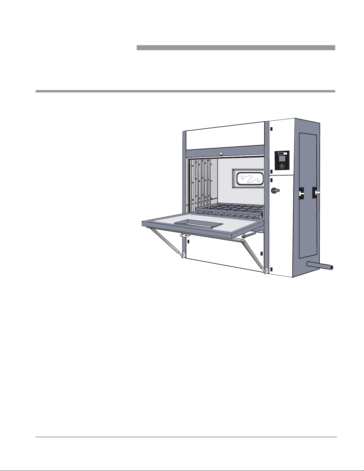
Figure 1–1. ,MTP 1800 Series Washers
MTP
The
cabinet- type, hydrospray washers. The units are designed to efficiently and
thoroughly clean and sanitize cages, bottles, debris pans and utensils used
in research animal care facilities.
Units are available in vertical or drop down door configurations. Units are
floor mounted and may be recessed through one or two walls or installed
free standing. Left side service access and control terminal location is
standard with right side service access and control terminal location
optional.
1800 series units are an automatic, heavy-duty, single chamber,
61301604086 1–1
Page 12
General Description
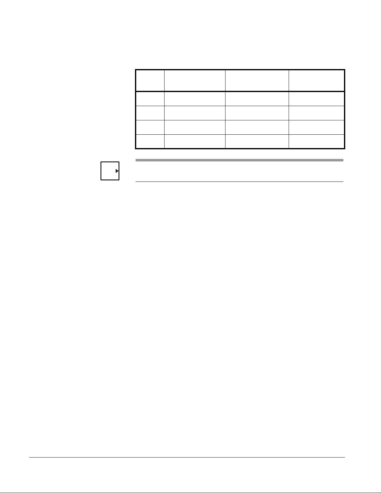
Models and dimensions are listed in Table 1-1.
Table 1–1. MTP 1800 Washer
NOTE
MODEL
1810 48” W x 32”H x 34”D 73”W x 82”H x 38.5”DVertical
1820 48” W x 32”H x 48”D 73”W x 82”H x 52.5”DVertical
1830 48” W x 32”H x 34”D 73”W x 82”H x 38.5”D Drop Down
1840 48” W x 32”H x 78”D 73”W x 82”H x 52.5”D Drop Down
The above dimensions are the maximum chamber opening. The load size
must be smaller to allow for loading clearances.
Routine operation consists of placing the load to be cleaned in the chamber,
close the chamber door, select the desired cycle, and press the cycle start
button. The washer automatically proceeds through the treatment process
and alerts the user when the process is complete. The user then opens the
chamber door and removes the cleaned load.
At the end of the processing period, the user places the unit in the
STANDBY mode. All processing functions will immediately stop and the
sump will automatically drain.
CHAMBER SIZE
(see note)
EXTERNAL
OVERALL SIZE
DOOR
CONFIGURATION
Standard Features
• Microcomputer Color Touch Screen Control
• Twelve User Programmable Cycles
• Automatic Seven Phase Treatment Cycles
• Program Access Code Security
• Wash and Rinse Temperature Assurance
• Built-In Service Diagnostics
• Personnel Safety System
• Water Conservation System
• 7.5 HP Pump (Models 1810 & 1830)
• 10 HP Pump (Models 1820 & 1840)
• Automatic Sump Water Level Control
• Automatic Self-Cleaning Debris Filter
• Agent Injections Ports and Contacts
• Stainless Steel Steam Coil Heating
• Vertical or Drop Down Doors
• All Stainless Steel Construction
• Full Work Area Stainless Steel Grating
• Insulated Chamber Construction
• Left or Right Service Side Installation
1–2
Page 13

Series 1800 Washers
Optional Features
• Strip Chart Printer
• RS232 Port for Data Download
• Double Door Pass Through
• Double Door Interlocks for Manual Doors
• Powered Vertical Doors with Interlocks
• Electric Stainless Steel Sump Heaters
• Stainless Steel Treatment Components
• Cold Water Pre-Wash Treatment
• Non-Recirculated Final Tap Water Rinse
• Non-Recirculated Final Pure Water Rinse
• House Tap Water Temperature Booster
• Pure Water Temperature Booster
• Automatic Agent Injection Systems
• Internal Chamber Illumination
• Stainless Steel Automatic Damper
• Power Exhaust Fan
• Vented/Non-Vented Vapor Removal Condenser
• Drain Discharge Cool-Down Systems
• Treatment Solution pH Neutralization Systems
• Removable Center Header
• Recessed or Free Standing Cabinet Installations
• Seismic Design
• Knocked Down Shipment
• Modem Troubleshooting
Accessories
• Mouse Box Processing Rack
• Rat Box Processing Rack
• Pan Processing Rack
• Transfer Cart
• Feeder Bottle Baskets
• Custom Accessories
61301604086 1–3
Page 14
General Description
EXTERIOR COMPONENTS
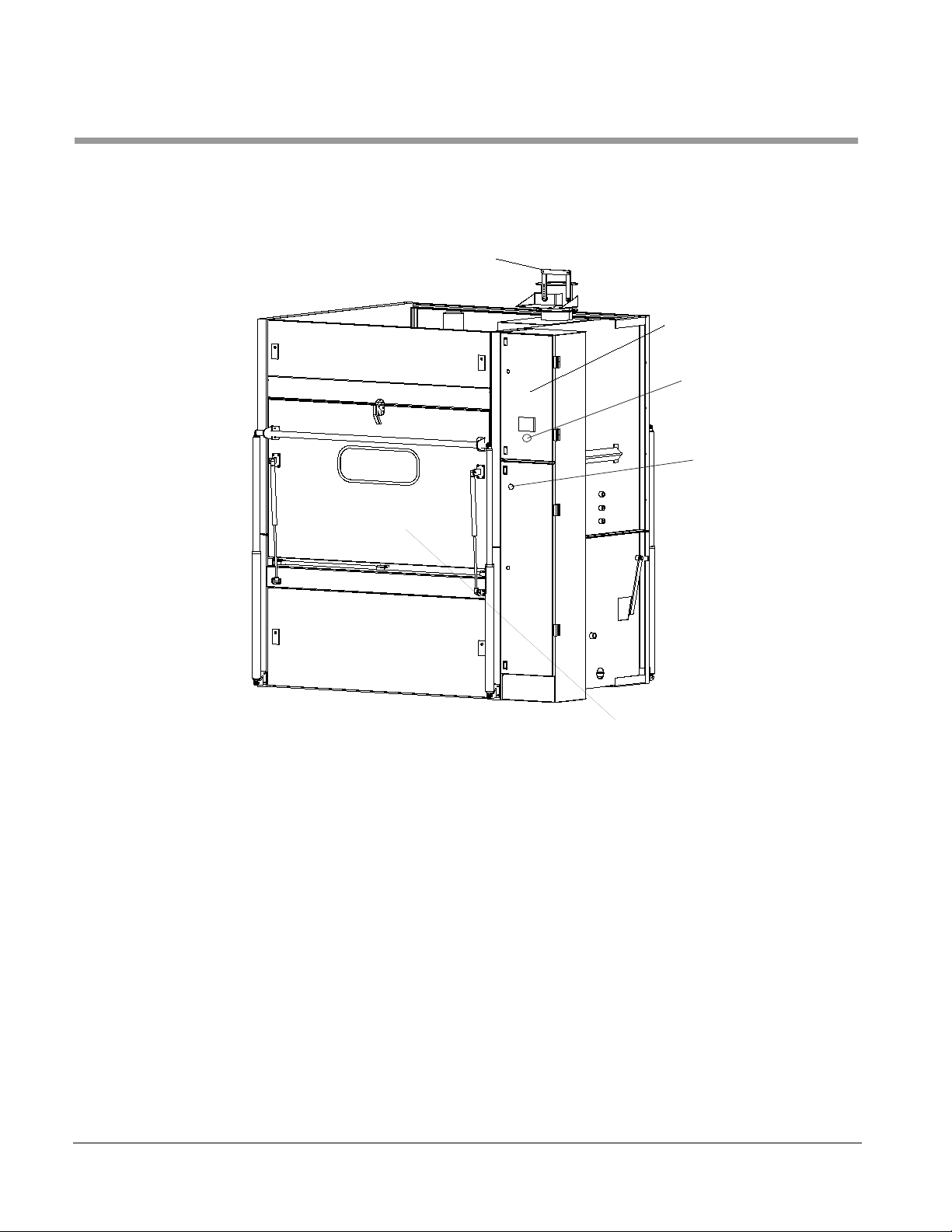
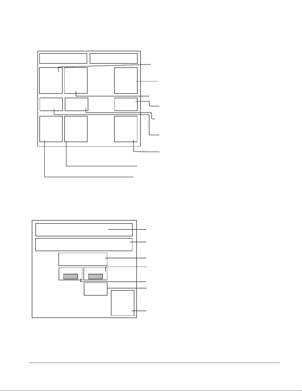
Figure 1–2. EXTERNAL COMPONENTS
Exhaust Damper
Control Panel
Emergency Stop
Switch
Electrical Disconnect
Switch
Control Panel
Emergency Stop Switch
Electrical Disconnect Switch
Exhaust Damper
1–4
Drop Down Door
Provides a pressure sensitive touch screen for the user that is connect to a
Programmable Logic Control (PLC) located in the Control Box. Enables the
user to select, program, and monitor processing cycles.
The EMERGENCY STOP Switch should be used to terminate all treatment
functions and activate the audible alarms.
Rotate the Electrical Disconnect Switch to the:
• ON position to energize the washer.
• OFF position to de-energize the washer.
Opens fully during the Exhaust phase of a wash cycle to permit residual
vapors to escape from the chamber. Closed 70% during the wash and rinse
phases of the wash cycle.
Page 15
Series 1800 Washers
Alarm (Not Shown)
Service Area (Not Shown)
Dispenser (Option)
Automatic Self-Cleaning Debris Filter
Sounds an audible alert when:
• A cycle is completed (Pulsing/Audible alarm).
• A cycle is aborted.
• The Programmable Logic Controller (PLC) detects processing
problems.
Contains piping, valves, pumps, control box, manifold drive motor, etc.
An optional Chemical Dispenser automatically pumps the required chemical
into the water solution held in the sump. The Dispenser is activated during
the Wash phases of a processing cycle.
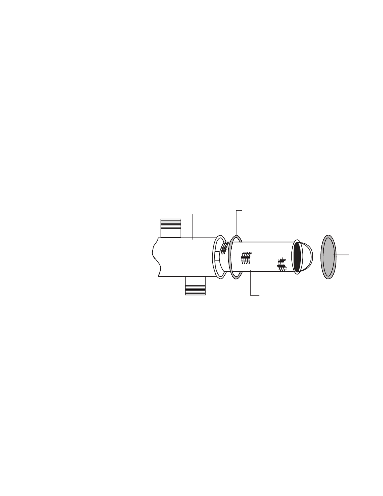
The output of the wash pump is provided with a self-cleaning debris filter
screen having perforations smaller than the spray jet orifices to prevent
plugged jets. The filter is attached to the Treatment Pump and is back
flushed by a ball valve operated by the control system. The filter screen can
be accessed without the use of tools.
FILTER
HOUSING
O-RING
Part # P0015136
FILTER SCREEN
Part # B300232A
A screen is provided at the input to the pump to prevent large debris from
entering the pumping system.
The automatic self-cleaning debris filter screen should be rinsed clean daily,
removing any debris. See Table 4–1, “Maintenance Schedule–Standard,” on
page 4–1.
61301604086 1–5
Page 16
General Description
Door Configurations
OPEN DOOR Switches
Emergency Stop Switches (Load and Unload End)
Unload End Control Panel
VERTICAL SLIDING DOOR (Models 1810 and 1820
The unit contains a manually operated, counter balanced, vertical sliding
door. The door is double wall construction with insulation. A tempered glass,
water-tight observation window is provided in both the load and optional
unload doors.
DROP DOWN DOOR (Models 1830 AND 1840)
The unit contains a manually operated, counter balanced, drop down door.
The door is double wall construction with insulation. A tempered glass,
water-tight observation window is provided in both the load and optional
unload doors. A stainless steel washing rack that rolls out onto the door is
included for ease of loading and unloading.
Stops Washer operation if a Load or Unload End door is opened during a
cycle. Prevents the start of washer operation if a door is not closed. Lights
indicating an open door are located on the Load and Unload End Control
Panels.
Pressing the EMERGENCY STOP switch terminates all functions of the
washer and sounds the alarm.
Displays the operational status of the unit at the Unload End
Figure 1–3. UNLOAD END CONTROL PANEL
IN
PROGRESS
CYCLE
COMPLETE
EMERGENCY
STOP
IN PROGRESS INDICATOR
Displays an amber light for the duration of an ongoing processing cycle. The
IN PROGRESS Indicator is located at the Unload End of the Washer.
CYCLE COMPLETE INDICATOR
Displays a green light whenever the Electrical Disconnect Switch is turned
ON, as long as a cycle is not operating. The light turns off at the start of a
processing cycle. When the cycle ends, the light comes back on. The
CYCLE COMPLETE Indicator is located at the Unload End of the Washer.
1–6
Page 17
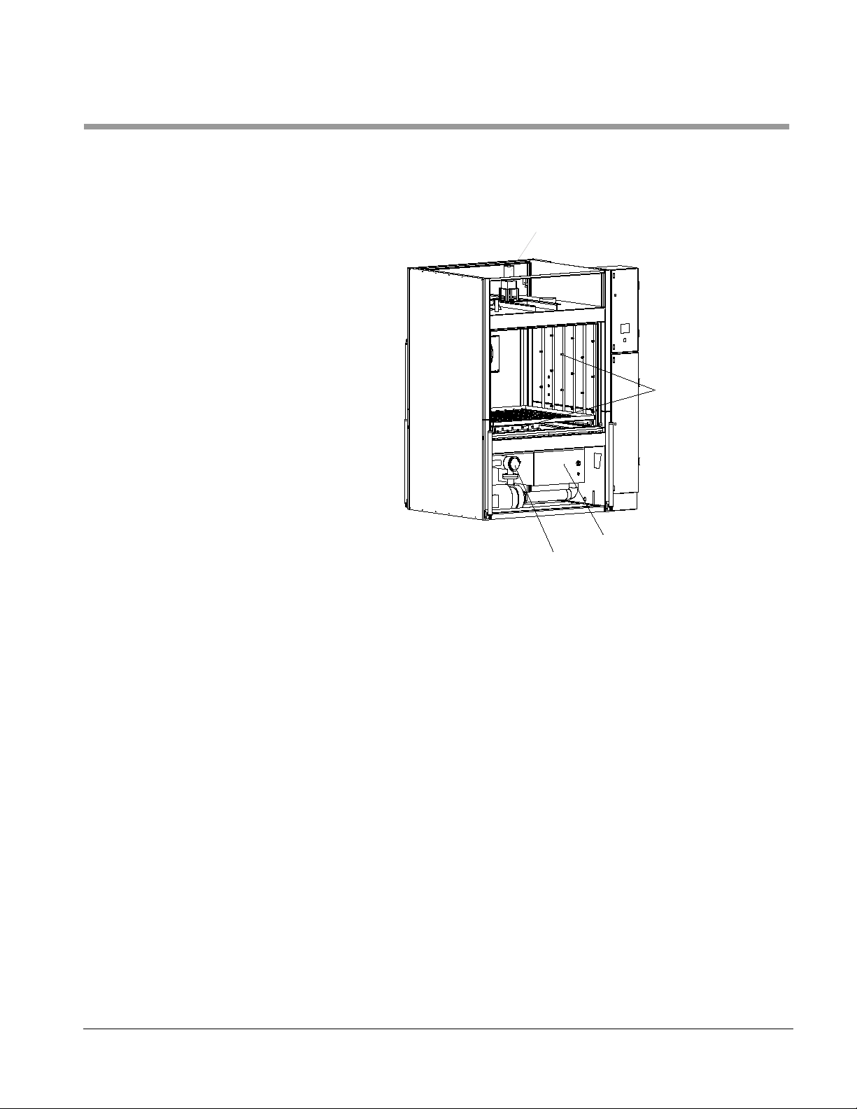
INTERIOR COMPONENTS
Series 1800 Washers
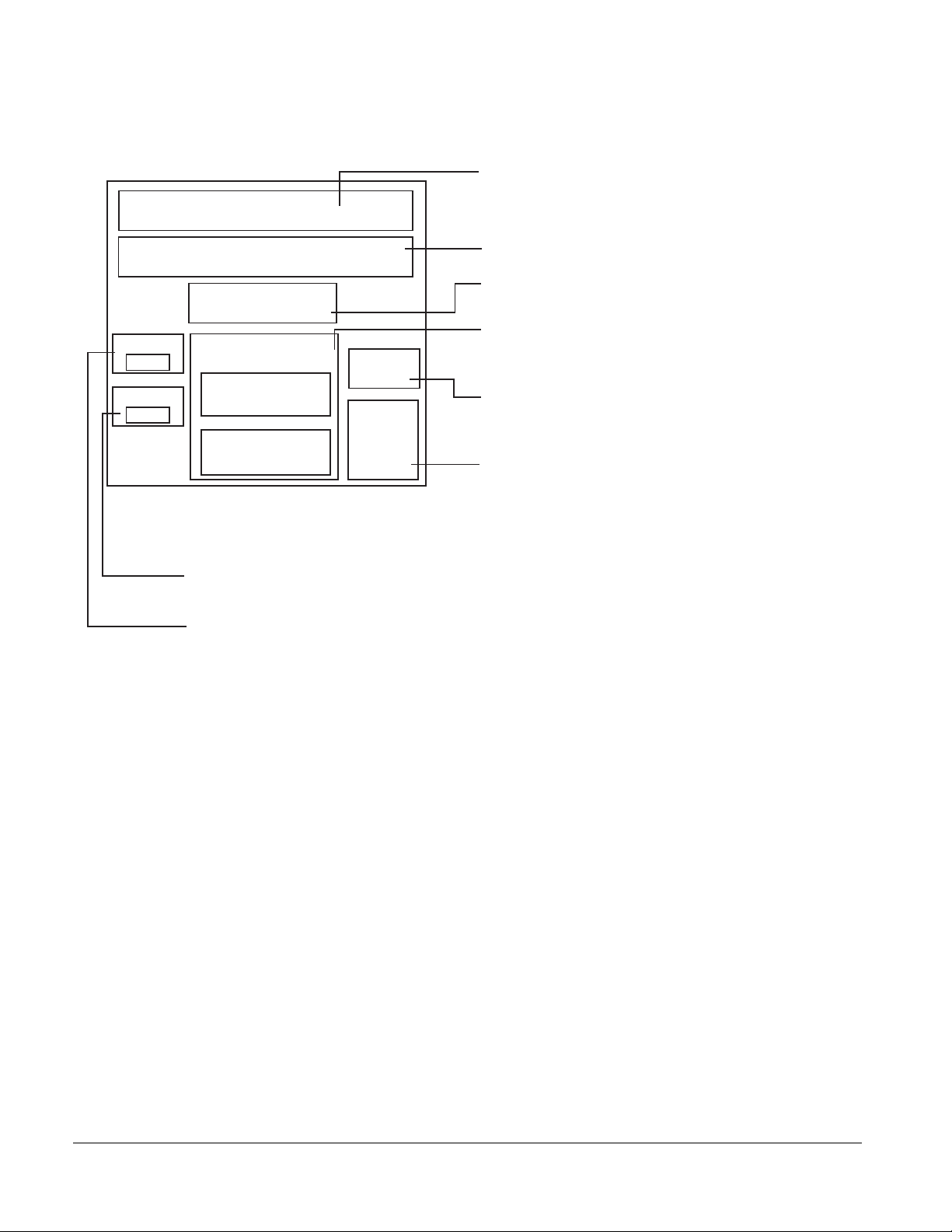
Figure 1–4. Internal Components (door and front panels not shown)
Header Drive Motor
Spray Manifold
Spray Manifold
Guide Rail (not shown)
Sump
Header Drive Motor
Sump
Self Cleaning Debris Filter
Delivers the various wash and rinse spray treatments to the load during a
processing cycle. Vertical and horizontal sections - fitted with spray nozzles
- make up the complete assembly.
Functions as a restraint to keep items, such as utensil carts, from being
improperly positioned. Four rails are provided on the inside of the chamber
door.
Holds the supply of solution (wash and rinse) that is pumped to the Spray
Manifold during a processing cycle. During processing, it collects all
drainage for recirculation. A steam heating coil installed in the sump
maintains the temperature of the wash solution, and other treatment
solutions - if specified.
Moves the Spray Manifold back and forth inside the chamber during the
processing cycles.
61301604086 1–7
Page 18

General Description
MOST COMMON OPTIONS
Strip Chart Printer
Vertical Powered Door
Double Door Pass-Through
Electric Heat
Automatic Agent Injection System
A strip chart printer with paper take-up, records all cycle program and inprocess performance data. Each cycle program, including time and
temperature set points, may be printed on demand. In-process cycle data is
automatically printed at the beginning and end of each cycle phase, as well
as at the beginning and end of each cycle phase, to provide a chronological
time/temperature profile of actual cycle performance.
The door is powered open and closed to permit ease in loading and
unloading the chamber. The system includes door activation switches and
status lights at the door location, which are wired to the automatic control
system.
The unit is provided with an additional door for pass through operation and
is complete with an unload end user control panel.
Stainless steel, electric immersion heaters are provided in the sump in place
of the steam coil heater to maintain the recirculated treatment solution
temperature. The unit requires a separate electrical connection.
TIME BASED
A non-monitored, time based, volumetric type injection system is provided
to automatically meter user supplied liquid cleaning agent into the sump.
(Two systems are required if an alkaline and acid treatment solution are to
be used).
Internal Chamber Illumination
MONITORED
A monitored proportional type injection system is provided to automatically
inject user supplied liquid cleaning agent into the sump. The treatment
solution concentration is sensed with a probe, and a proportional amount of
agent is injected to attain and maintain the selected agent concentration.
(Two systems are required if an alkaline and acid treatment solution are to
be used.)
An exterior vapor proof port and light is provided to illuminate the chamber
interior.
1–8
Page 19

Series 1800 Washers
Automatic Self-Cleaning Debris Filter
Drain Discharge Cooldown System
Removable Center Washing Header
The output of the wash pump is provided with a self-cleaning debris filter.
The filter is attached to the treatment pump and is back-flushed by a ball
valve operated by the control system. The filter screen may be accessed
without the use of tools.
An additional perforated stainless steel debris basket is provided above the
recirculated tank to prevent large debris from entering the piping and pump
system. The screen can be easily removed for cleaning.
NON-MONITORED
Cold tap water is automatically injected into the drain discharge to lower the
discharge temperature to below 140°F before entering into the building’s
drain system.
MONITORED
The discharge of the machine is drained into a stainless steel holding tank.
The system senses the discharge temperature with a probe and adds the
required amount of cold water to lower the discharge temperature to below
140°F before discharging tot he building’s drain system.
An additional header is provided in the center of the chamber to increase
the washing capacity of the unit. This header can be removed to
accommodate larger items to be washed. This option increases the overall
washer width by 8 inches.
61301604086 1–9
Page 20

General Description
ACCESSORIES
Mouse Box Rack
Rat Box Rack
Pan Rack
Transfer Cart
Two stainless steel racks are provided.
• Models 1810 and 1830 — have the capacity to process 24 standard
mouse shoe boxes per load. (48 boxes per load if the machine is
equipped with center washing header.)
• Models 1820 and 1840 — have the capacity to process 40 standard
mouse shoe boxes per load. (60 boxes per load if the machine is
equipped with center washing header.)
Two stainless steel racks are provided.
• Models 1810 & 1830 — have the capacity to process 8 standard rat
shoe boxes per load. (18 boxes per load if the machine is equipped
with center washing header.)
• Models 1820 & 1840 — have the capacity to process 16 standard rat
shoe boxes per load. (16 boxes per load if the machine is equipped
with center washing header.)
Two stainless steel racks are provided to process pans with a maximum
width of two inches.
A stainless steel transfer cart is provided to transport racks to and from the
washer. The transfer card interfaces with the chamber opening to permit
easy transfer of racks into and out of the chamber.
Feeder Bottle Baskets
Stainless steel bottle baskets are provided for processing 8, 16, or 32 oz.
bottles. Baskets are configured in a 4 x 6 pattern.
1–10
Page 21

General Machine Operation
Series 1800 Washers
Automatic Seven Phase Treatment Cycle
Operation
Treatment Schedule
The standard treatment cycle consists of a Prewash, Wash 1 and Soak,
Wash 2 and Soak, Rinse 1, Rinse 2, Rinse 3, and an Exhaust. All cycle
phases are adjustable from 0-60 minutes. All wash and rinse treatments are
recirculated under pump pressure. The cycle, once activated, is completely
automatic. Additional cycle treatment phases are available.
At the start of the processing period, the user places the load to be cleaned
n the chamber, closes the door, selects the desired cycle and presses the
cycle start button. The washer automatically proceeds through the
treatment process and alerts the user when the process is complete. The
user then opens the chamber door and removes the cleaned load.
PREWASH
Hot water from house supply fills the sump or water remaining in the sump
from Rinse 3 of the previous cycle is recirculated through the jet spray
system under pump pressure and pumped to drain upon completion. Phase
time and temperature is user programmable form 0-60 minutes and from
120 - 190°F respectively.
WASH 1
Hot water from the house supply fills the sump and the wash agent is
automatically added. The treatment solution is recirculated through the jet
spray system and is pumped to drain upon completion. The phase time and
temperature are user-programmable from 0 to 60 minutes and from
120 - 190°F respectively.
Soak Option: A subsequent soak period may be programmed from
0-60 minutes, to permit the detergent solution to work on the load
before proceeding to the second wash and/or rinse treatments.
WASH 2
Hot water from the house supply fills the sump and the wash agent is
automatically added. The treatment solution is recirculated through the jet
spray system and is pumped to drain upon completion. The phase time and
temperature are user-programmable from 0 to 60 minutes and from
120 - 190°F respectively.
Soak Option: A subsequent soak period may be programmed from
0-60 minutes, to permit the detergent solution to work on the load
before proceeding to the rinse treatments.
RINSE 1
Hot water from the house supply fills the sump and is recirculated through
the jet spray system under pump pressure and pumped to drain upon
completion. The phase time and temperature are user-programmable from
0 to 60 minutes and from 120 - 190°F respectively.
61301604086 1–11
Page 22

General Description
RINSE 2
Hot water from the house supply fills the sump and is recirculated through
the jet spray system under pump pressure and pumped to drain upon
completion. The phase time and temperature are user-programmable from
0 to 60 minutes and from 120 to 190°F respectively.
RINSE 3
Hot water from the house supply fills the sump and is recirculated through
the jet spray system under pump pressure and pumped to drain upon
completion. The phase time and temperature are user-programmable from
0 to 60 minutes and from 120 - 190°F respectively.
Non-Recirculated Option: Hot water from house supply under house
pressure is sprayed directly through a separate jet system and is
drained upon completion. Phase time is user programmable from
0 - 60 minutes.
EXHAUST or VAPOR REMOVAL
The unit stands idle for a sufficient period of time to allow the facility vent
system to remove vapor from within the chamber. The phase time is userprogrammable from 0 to 60 minutes.
TEMPERATURE GUARANTEE SYSTEM:
All phases of the wash cycle except Soak and Exhaust have the option to
select a Temperature Guarantee Mode. When selected, this causes the unit
to fill and spray water normally for that phase, without allowing the main
timer to start counting down until the set-point temperature has been
attained. If at any time the sump temperature should fall below the set-point,
the main timer stops until the temperature exceeds the set-point. Failure to
do so in a set period of time generates a “too long to heat” alarm.
1–12
Page 23

INTRODUCTION
Section 2 The Control Panel
Your unit has one of the following control panels:
• TOUCH CONTROL PANEL (TCP), see page 2–2
• LED CONTROL PANEL, see page 2–16
The Control Panel on this unit provides the user with an interface linked to
the Programmable Logic Controller (PLC) located in the Control Box. Using
this panel, the user is able to:
• Select a processing cycle.
• Program cycle phase timing
• Program cycle phase temperature
• Start a processing cycle
• Monitor the status of an ongoing cycle.
• Manually drain the washer’s sump.
In addition to the above, supervisory personnel are able to do:
• Access load counters and time display
• Protect cycle programming
61301604086 2–1
Page 24
The Control Panel
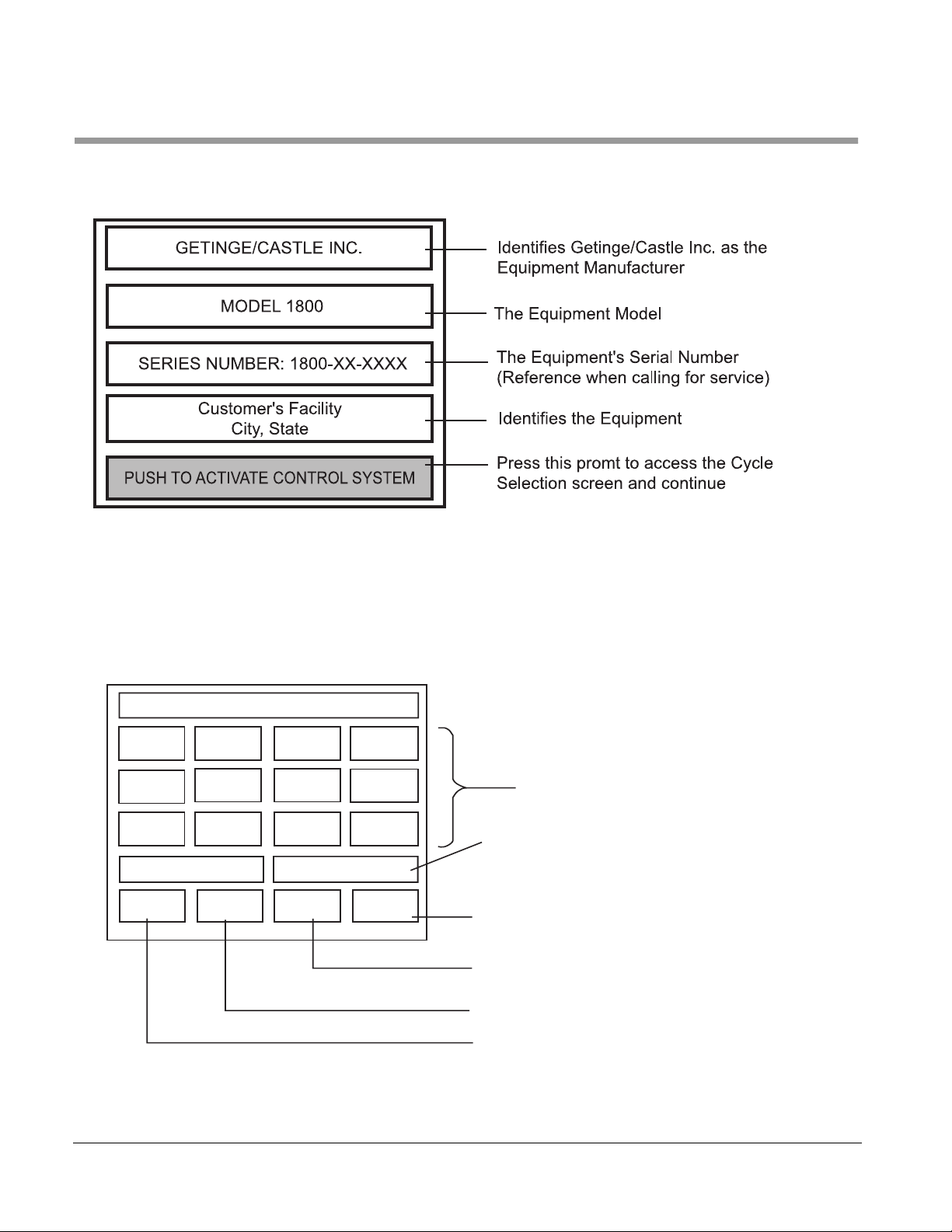
TOUCH CONTROL PANEL (TCP)
Control Screens
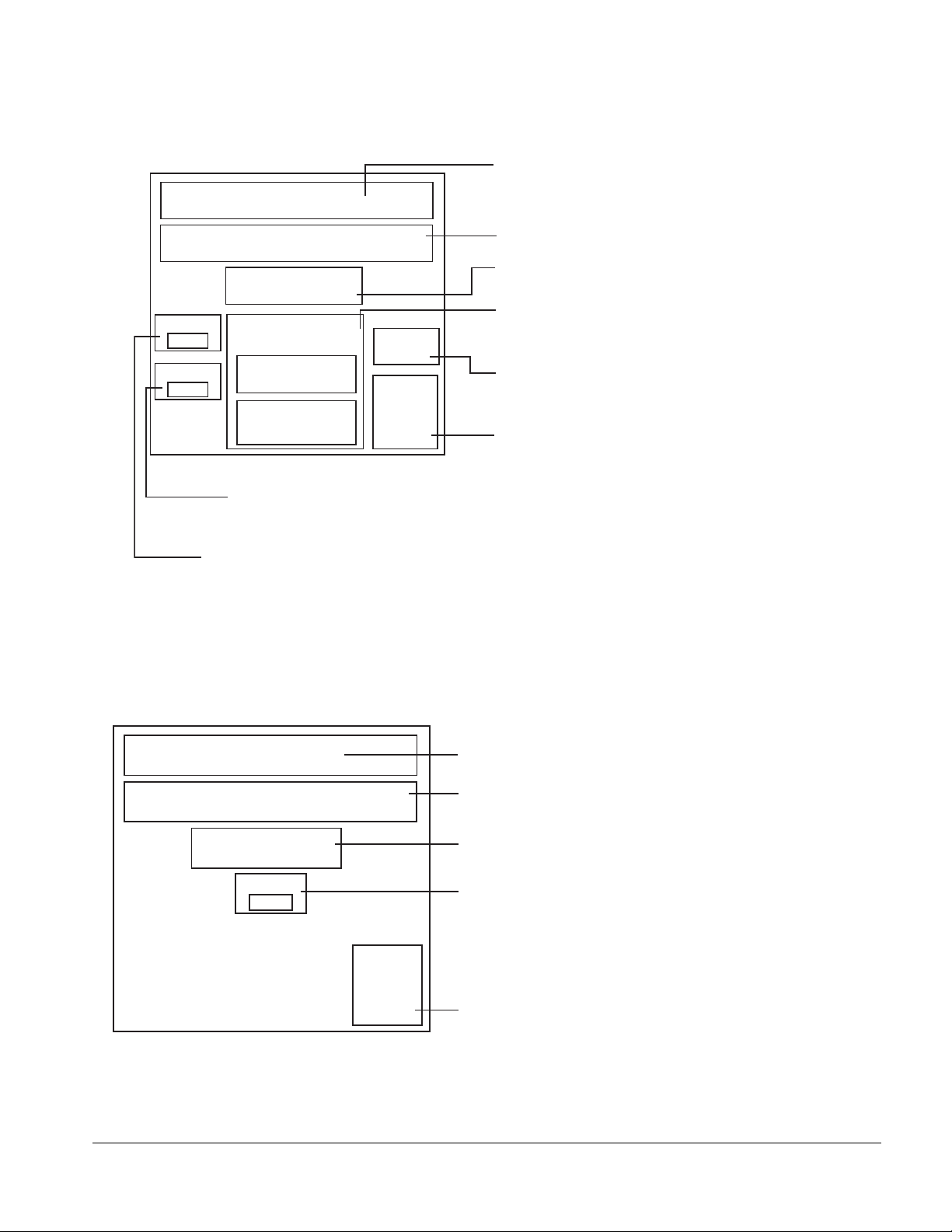
MACHINE CUSTOMER IDENTIFICATION SCREEN
CYCLE SELECTION SCREEN
Cycle
1
Cycle
5
Cycle
9
LOAD DOOR
MANUAL
MODE
Load Unit – Select Cycle – Review
Cycle
2
Cycle
6
Cycle
10
EVENT
PRINT OFF
Cycle
3
Cycle
7
Cycle
11
UNLOAD DOOR
PRINT
CYCLE
Cycle
4
Cycle
8
Cycle
12
REVIEW
CYCLE
Press the prompt of the desired
cycle of operation
Prompts are "read only" and not used as touch cells. When
the Load Door is open, "Load Door" will be back-lit red in
color. When the load door is closed, "LOAD DOOR" will be
back-lit blue in color. Note that the "UNLOAD DOOR" will
be available only on washers equipped with this option.
After operator has selected a cycle this prompt must be
pressed to be reviewed and show this cycle start prompt
Pressing this prompt will allow printer
to print cycle parameters
When this prompt is activated, live reading
will be printed during the cycle
Pressing this prompt will place controls in manual
mode to perform functions test
2–2
Page 25

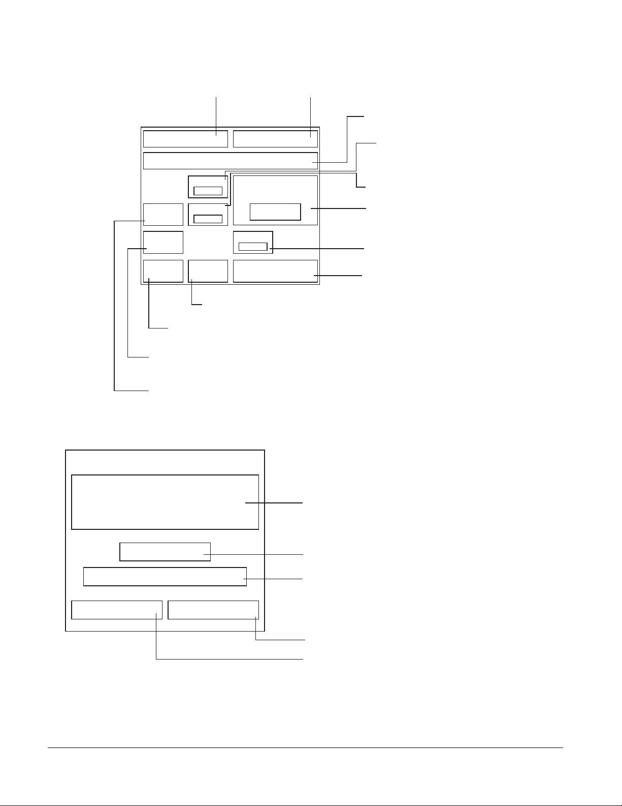
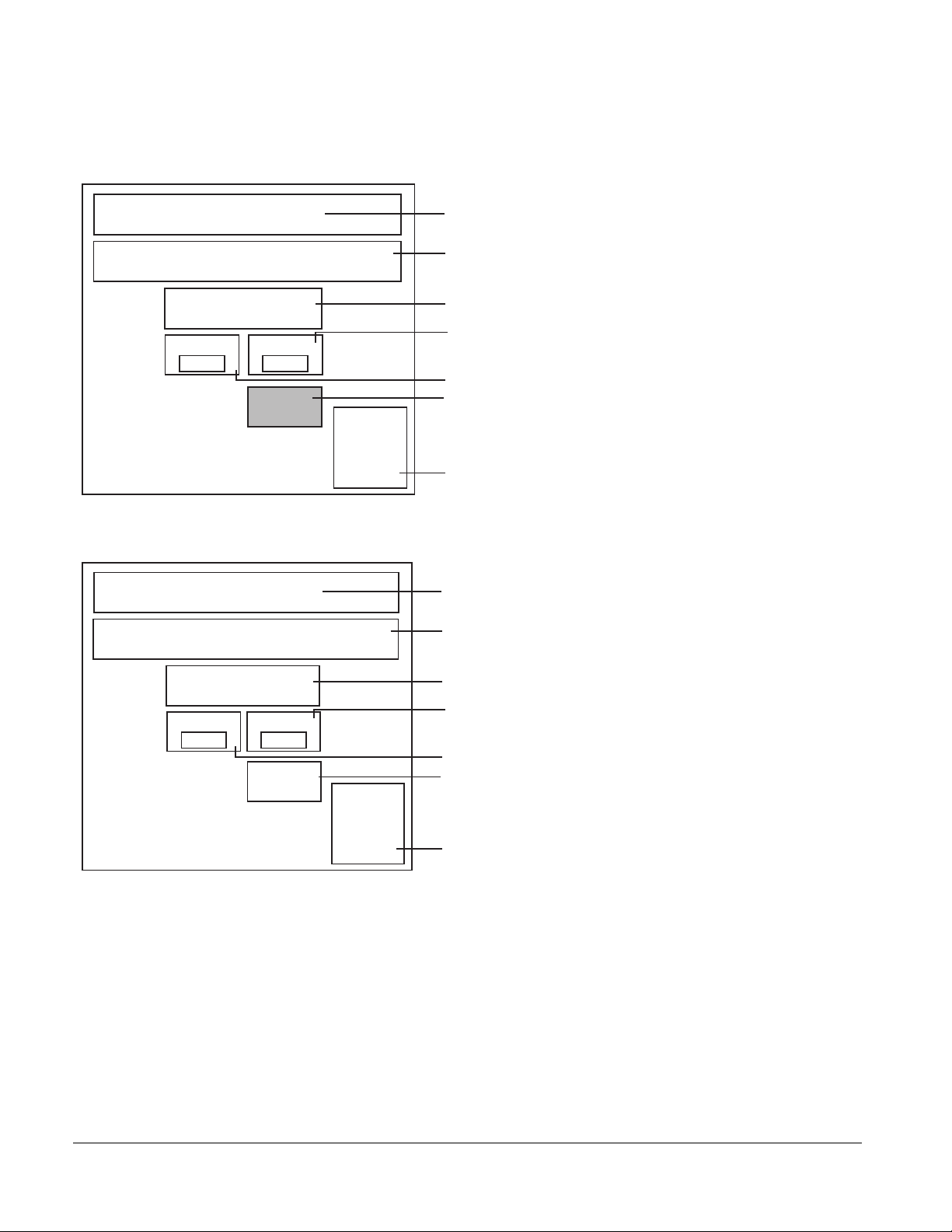
REVIEW PROGRAMMED PHASES SCREEN
Describes the current cycle selected
Describes the current control screen display
Series 1800 Washers
CYCLE 1
PREWASH
RINSE
1
REVIEW AND START OR PROGRAM
MAIN
MENU
WASH
1
RINSE
2
START
CYCLE
REVIEW PHASES
WASH
RINSE
PROGRAM
CYCLE
2
3
SOAK
EXHAUST
Illuminated prompts indicate phases
programmed to operate in this cycle
Displays available options for this
control screen
No Bottle
Washing
PRINT
CYCLE
To process bottles, user must press prompt
to change to ACTIVATE BOTTLE WASH OPTION.
Pressing this prompt will print selected
cycle parameters
Pressing this prompt will allow operator to change
parameters of cycle if password is keyed in to unlock
Depress to start selected cycle
Depress prompt to return to main menu
61301604086 2–3
Page 26
The Control Panel
Displays current cycle
CYCLE 1 PREWASH
NO ACTIVE ALARM
Temp Set
120
TEMP
GUAR’T
Sump
Fill
CYCLE
HOLD
Prompt will display during sump filling process
Prompt will display if the program has a
guarantee on the temperature of the sump
Sump Temp
130
Fill Temp
ANSWER
ALARM
Pressing this prompt will clear any timed alarm
Pressing this prompt will stop phase timer,
if hold prompt is pressed again, phase timer
will resume
Displays current phase of cycle
REMAIN TIME
120
190
CYCLE ABORT
Displays current alarm
Displays programmed sump
temperature parameter
Displays actual sump
Displays current remaining time in phase
Displays the house water fill temperature
Pressing this prompt will stop all functions
of washer and set the alarm
Cycle Complete Screen
CYCLE COMPLETE
CYCLE 1
TOTAL CYCLE TIME (MINUTES) 35
LOAD DOOR UNLOAD DOOR
Screen is displayed at end of cyle
Prompt will display completed
cycle number
Prompt will display total amount of time
used to process current cycle, in minutes
Prompt will display status of unload door
Prompt will display status of load door
2–4
Page 27
CYCLE PASSWORD
Enter
Password
Change
Password
Program Change Screen
Press this prompt then enter the password to unlock
Service
Password
operators program
This prompt is for Factory authorized personnel
Series 1800 Washers
Unlocked
Program
Cycle
Press to
change
P/W
MAIN
MENU
CYCLE 1
This prompt is used for changing the operator's password
LOCKED
This program is read only, showing the status of
program access (LOCKED )
This prompt is used for changing the password used in
Adjust
Calendar
Clock
unlocking the operator's program
This program is read only, showing the status of
program access (UNLOCKED )
This prompt is used in setting the time and date
Pressing this prompt will take screen back to MAIN MENU
Once the program has been unlocked this prompt will allow
access to the programming screens
Program Prewash #1 Screen
Displays current cycle
Program Prewash Menu
PREWASH ON
Displays phase of cycle to be programmed
Displays the status of phase (press prompt to toggle on)
Displays programmed temperature of sump
TIMER
120
TEMP
120
(Press prompt and key in new parameter)
Displays length of time phase will be activated
Guarantee
Off
NEXT
PHASE
This prompt allows the temperature guarantee to be on
or off
Press this prompt to advance menu to next phase screen
61301604086 2–5
Page 28
The Control Panel
Program Wash #1 Screen
Displays current cycle
CYCLE 1
PROGRAM WASH #1 MENU
AGENT WASH #1 ON
Timer
185
Sump Temp
165
AGENT SELECTION
Alkaline Agent - Drained
Acid Agent - Drained
Prompt will display current temperature parameter of
sump solution (pressing prompt, will allow new
parameter to be entered).
Displays length of time phase will be activated
Guarantee
Off
NEXT
PHASE
Displays phase of cycle to be programmed
Displays status of phase (press prompt to toggle on)
Agent selection prompt allows the programming of two (2)
different agent washes, alkaline or acid.
Displays the status of temperature guarantee
(press prompt to change status)
Press this prompt to advance menu to next phase screen
NOTE: SOME FEATURES SHOWN ON THE TOUCH PANEL MAY NOT BE AVAILABLE IF
OPTIONS WERE NOT SELECTED.
2–6
Page 29
CYCLE 1
Series 1800 Washers
Program Wash #2 Screen
Displays current cycle
PROGRAM WASH #2 MENU
AGENT WASH #2 ON
Timer
185
Sump Temp
185
AGENT SELECTION
Alkaline Agent - Drained
Acid Agent - Drained
Prompt will display current temperature parameter of
sump solution (pressing prompt, will allow new
parameter to be entered).
Displays length of time phase will be activated
Guarantee
Off
NEXT
PHASE
Displays phase of cycle to be programmed
Displays status of phase (press prompt to toggle on)
Agent selection prompt allows the programming of two (2)
different agent washes, alkaline or acid.
Displays the status of temperature guarantee
(press prompt to change status)
Press this prompt to advance menu to next phase screen
NOTE: SOME FEATURES SHOWN ON THE TOUCH PANEL MAY NOT BE AVAILABLE IF
OPTIONS WERE NOT SELECTED.
Program Soak Screen
CYCLE 1
PROGRAM SOAK MENU
SOAK ON
Timer
120
NEXT
PHASE
Displays current cycle
Displays phase of cycle to be programmed
Displays the status of phase (press prompt to toggle on)
Displays length of time phase will be activated
Press this prompt to advance menu to next phase screen
61301604086 2–7
Page 30
The Control Panel
Program Rinse #1 Screen
CYCLE 1
PROGRAM RINSE #1 MENU
RINSE #1 ON
Timer
120
Sump Temp
180
Guarantee
On
CYCLE 1
PROGRAM RINSE #2 MENU
Displays current cycle
Displays phase of cycle to be programmed
Displays the status of phase (press prompt to toggle on)
Displays programmed temperature of sump
(Press prompt and key in new parameter)
Displays length of time phase will be activated
This prompt allows the temperature guarantee to be on
or off
NEXT
PHASE
Press this prompt to advance menu to next phase screen
Program Rinse #2 Screen
Displays current cycle
Displays phase of cycle to be programmed
RINSE #2 OFF
Timer
0
Sump Temp
Guarantee
0
Off
Displays the status of phase (press prompt to toggle on)
Displays programmed temperature of sump
(Press prompt and key in new parameter)
Displays length of time phase will be activated
This prompt allows the temperature guarantee to be on
or off
NEXT
PHASE
Press this prompt to advance menu to next phase screen
2–8
Page 31

Program Rinse #3 Screen
Series 1800 Washers
CYCLE 1
PROGRAM RINSE #3 MENU
RINSE #3 ON
Timer
120
SAVED
SUMP
Sump Temp
120
Guarantee
Off
Displays status of water used in Rinse 3
when complete. Water can either be
dumped to drain or saved to sump for
prewash of next cycle.
Calendar Clock
Displays current cycle
Displays phase of cycle to be programmed
Displays the status of phase (press prompt to toggle on)
Displays programmed temperature of sump
(Press prompt and key in new parameter)
Displays length of time phase will be activated
This prompt allows the temperature guarantee to be on
or off
NEXT
PHASE
Press this prompt to advance menu to next phase screen
CALENDAR CLOCK-ENTER NEW VALUES
THEN PRESS “SAVE CHANGES” PROMPT
PLC Month12PLC Day10PLC Year
00
New Month10New Day
1
PLC Hour10PLC Minute
56
New Hour9New Minute
14
New Year
01
SAVE
CHANGES
BACK TO
ACCESS
SCREEN
Displays the current screen description
This prompt is read only, displays current Year
This prompt is read only, displays current Day
This prompt is read only, displays current Month
This prompt is used for changing the Year, depress
prompt then enter the desired Year
This prompt is used for changing the Day, depress
prompt then enter the desired Day
This prompt is used for changing the Month, depress
prompt then enter the desired Month
This prompt is read only, displays current Hour
This prompt is read only, displays current Minute
Depressing this prompt will take operator back to
Main Access Screen
Depressing this prompt will save all changes made to
settings in calendar – clock screen
This prompt is for changing the Minute, depress prompt
then enter the desired Minute
This prompt is for changing the Hour, depress prompt
then enter the desired Hour
61301604086 2–9
Page 32

The Control Panel
MANUAL MODE SCREEN
MANUAL MODE
Treatment
Pump Off
Alkaline
Detergent
Sump Heat
MAIN
MENU
Jet Valve
Open
Acid
Detergent
Damper
Select Desired
Function/Abort to Quit
components. Press prompt again to stop
selected component or "ABORT" to stop all
components activated.
Press any prompt to activate selected
Drain
Valve
Header
Drive
All safety interlocks are intact in the manual
mode. The wash or rinse pumps will not
Acid
Neutralize
Drain
Cooling
ANSWER
ALARM
ACCESSING THE MANUAL MODE SCREEN
Sump
Fill
ABORT
operate if there is not enough water in the
sump. The Wash pump will operate for 60
seconds without water.
Sump fill will not activate if sump is full.
Sump fill will stop when sump is full.
1.From the CUSTOMER IDENTIFICATION screen, press “PUSH TO
ACTIVATE CONTROL SYSTEM”
2. From the CYCLE SELECTION screen, Press “MANUAL MODE”.
Your screen may be different from the one shown. This screen shows all
options for the machine. Your machjine may not have all these features
installed.
2–10
Page 33

Cycle Programming
Series 1800 Washers
Example: Programming a Sample Cycle
PHASE
Sample Cycle 1—Touch Control Panel
Pre-wash 60 120 Off
Wash 1 300 170 Guaranteed Acid
Wash 2 300 170 Off Alkaline
Soak None
Rinse 1 120 180 Guaranteed
Rinse 2 00 Off
Rinse 3 60 120 Off Save
The following is a SAMPLE cycle along with detailed instructions on how to
program the cycle for your reference.
TIME
(seconds)
TEMPERATURE
(°F)
TEMPERATURE
GUARANTEE
SAVE/DUMP
TO DRAIN
AGENT
Cycle
1
Cycle
5
Cycle
9
LOAD DOOR
MANUAL
MODE
Load Unit – Select Cycle – Review
Cycle
2
Cycle
6
Cycle
10
EVENT
PRINT OFF
Cycle
3
Cycle
7
Cycle
11
UNLOAD DOOR
PRINT
CYCLE
Cycle
4
Cycle
8
Cycle
12
REVIEW
CYCLE
CYCLE SELECTION SCREEN:
Programmer should-
➢ Press CYCLE 1 prompt
➢ Select REVIEW CYCLE
61301604086 2–11
Page 34

The Control Panel
CYCLE SELECTION SCREEN
Programmer should-
CYCLE 1
PREWASH
RINSE
1
WASH
1
RINSE
2
REVIEW PHASES
WASH
RINSE
REVIEW AND START OR PROGRAM
MAIN
MENU
CYCLE PASSWORD
Enter
Password
START
CYCLE
Change
Password
PROGRAM
CYCLE
SERVICE PASSWORD
➢ Select PROGRAM CYCLE to enter the access screen
2
3
SOAK
EXHAUST
PRINT
CYCLE
CYCLE SELECTION SCREEN
Programmer should-
Press ENTER PASSWORD prompt
➢
➢
Type in correct password “12345”, press ENTER,
Service
Password
then press DONE. This will unlock the system.
➢
Select PROGRAM CYCLE
2–12
Unlocked
Program
Cycle
Press to
change
P/W
MAIN
MENU
Adjust
Calendar
Clock
LOCKED
Service
Menu
Page 35

CYCLE SELECTION SCREEN:
Programmer should-
Series 1800 Washers
CYCLE 1
Program Prewash Menu
PREWASH ON
TIMER
120
TEMP
120
Guarantee
Off
➢ Press PREWASH to set the phase ON.
➢ Select TIMER, set phase time to 60 seconds.
➢ Select TEMP, set temperature to 120°F.
➢ Press NEXT PHASE button when all paramteters
are set.
NEXT
PHASE
CYCLE SELECTION SCREEN:
Programmer should-
PROGRAM WASH #1 MENU
Timer
300
Sump Temp
165
CYCLE 1
AGENT WASH #1 ON
AGENT SELECTION
Alkaline Agent
➢ Press AGENT WASH #1 prompt to ON.
➢ Set phase time to 300 seconds.
➢ Set phase temp to 165°F .
➢ Set tank #1 to 165°F
➢ Press TEMP GUARANTEE button to OFF.
➢ Press AGENT WASH #1 prompt to ON.
Guarantee
Off
NEXT
PHASE
61301604086 2–13
Page 36

The Control Panel
CYCLE SELECTION SCREEN:
Programmer should-
PROGRAM WASH #2 MENU
Timer
300
Sump Temp
165
CYCLE 1
AGENT WASH #2 ON
AGENT SELECTION
Acid Agent
➢ Press AGENT WASH #2 prompt to ON.
➢ Set phase time to 300 seconds.
➢ Set phase temp to 165°F.
➢ Press temp guarantee button to OFF.
➢ Select ALKALINE AGENT for the agent selection.
➢Press NEXT PHASE to continue.
Guarantee
Off
NEXT
PHASE
CYCLE SELECTION SCREEN:
Programmer should-
CYCLE 1
PROGRAM RINSE #1 MENU
RINSE #1 ON
Timer
120
Sump Temp
185
Guarantee
On
PHASE
➢ Press RINSE #1 prompt to ON.
➢ Set phase time to 120 seconds.
➢ Set phase temp to 185°F.
➢ Press temp guarantee button to ON.
➢ Press NEXT PHASE to continue.
NEXT
2–14
Page 37

CYCLE SELECTION SCREEN:
Programmer should-
Series 1800 Washers
CYCLE 1
PROGRAM RINSE #2 MENU
RINSE #2 OFF
Timer
0
Sump Temp
0
Guarantee
Off
PHASE
➢Press RINSE #2 prompt to OFF.
➢ Set phase time to 30 seconds.
➢ Set phase temp to 140°F.
➢ Set GUARANTEE to OFF.
➢Press NEXT PHASE to continue.
NEXT
CYCLE SELECTION SCREEN:
Programmer should-
CYCLE 1
PROGRAM RINSE #3 MENU
RINSE #3 ON
Timer
120
SAVED
SUMP
Sump Temp
120
Guarantee
Off
PHASE
➢ Depress RINSE #3 prompt to “on”.
➢ Set phase time to 60seconds.
➢ Set phase temp to 180°F.
➢ Set to GUARANTEE to OFF
➢Set phase to SAVED SUMP
➢Press NEXT PHASE to continue.
NEXT
61301604086 2–15
Page 38

The Control Panel
LED CONTROL PANEL
Key Locations
MESSAGE
ALARM
GETINGE CASTLE, INC. MTP MODEL 18XX
CAGE AND BOTTLE WASHER
START
ABORT
MANUAL
SELECT
CYCLE
ENTER
SERVICE
MODE
SILENCE
ALARM
REVIEW
CYCLE
EXIT
SERVICE
MODE
EVENT
PRINT
ON/OFF
PROGRAM
CYCLE
PRINT
CYCLE
LAST
MESSAGE
NEXT
MESSAGE
PAG E
UP
PAG E
DOWN
PRINT
SCREEN
SETUP
HELP
SECTION 1 SECTION 2
The above screen has been separated into 2 sections
• Section 1— Function keys
• Section 2— Data Entry keys
➧
12
ALARM
➧
ACK
56
4
➧
8
7
TOGGLE
0
±
PRINTRUN
+
CLEAR
3
DELETE
➧
-
E
9
N
T
E
R
.
Information on each section follows.
2–16
Page 39

Section 1— Function keys
Series 1800 Washers
START
ABORT
MANUAL
SELECT
CYCLE
ENTER
SERVICE
MODE
SILENCE
ALARM
REVIEW
CYCLE
EXIT
SERVICE
MODE
EVENT
PRINT
ON/OFF
PROGRAM
CYCLE
PRINT
CYCLE
FUNCTION KEY FUNCTION
START Start the selected cycle.
ABORT Stop all functions of washer.
MANUAL MODE Enter the manual mode.
SELECT CYLES Access cycle selection screen.
ENTER SERVICE
MODE
For authorized service technician only.
SILENCE ALARM Silence audible alarm.
REVIEW CYCLE Review selected cycle
EXIT SERVICE
MODE
EVENT PRINT
ON/OFF
Exit service mode and return to stand-by
screen.
Record live readings of selected cycle as
load is being processed
PROGRAM CYCLE Access selected cycle program for
parameter changes.
PRINT CYCLE Print parameters of selected cycle.
61301604086 2–17
Page 40

The Control Panel
Section 2— Data Entry keys
LAST
MESSAGE
NEXT
MESSAGE
MESSAGE
Used to review last screen
Used to review next
available screen
LAST
MESSAGE
NEXT
PAG E
UP
PAG E
DOWN
PRINT
SCREEN
12
ALARM
➧
4
SETUP
7
HELP
±
Key/Function
HELP
Used to receive help
information
±
Used for the #2 or
to move cursor up
2
➧
ACK
56
➧
8
0
+
➧
-
TOGGLE
3
9
.
CLEAR
DELETE
E
N
T
E
R
-
TOGGLE
Used for the #9
9
Used to activate
components or deactivate
.
components in Manual
Mode.
PAG E
UP
PAG E
DOWN
SETUP
Used to scroll to
previous page
Used to scroll to next page
Used for the #1
Used for the #4 or
to move cursor left
Used for the #7 or
place TCP into direct
7
MODEM contact
ALARM
ACK
+
Used for the #5
5
Used for the #8 or
to move cursor down
8
Used for the #0
0
Used for the #3
3
Used for the #6 or
to move cursor right
6
CLEAR
DELETE
E
N
T
E
R
Used to clear old
parameters
Not used
Used to enter new
parameter
2–18
Page 41

Series 1800 Washers
Control Sequences
START UP
Turn the power on to the unit. The unit runs a diagnostic test.
Once the controller runs the test, the display screen shows
“MTP Model 18XX Cage and Bottle Washer. The unit is now in
the standby mode and ready to be used or programmed.
OPERATION
At the start of the processing period, the user activates the unit for
automatic operation. The unit automatically advances to the READY state
when the required operational conditions are attained.
The operator places the load to be cleaned in the chamber, closes the
chamber door, selects the desired cycle and presses the cycle start switch.
The washer automatically proceeds through the treatment process and
alerts the user when the process is complete. The user then opens the
chamber door and removes the cleaned load.
At the end of the processing period, the user places the unit in the
STANDBY mode. All processing functions stop and the sump and optional
treatment solution storage tanks automatically drain.
ALARM
If an alarm should sound at any time, press “SILENCE ALARM”
to turn the sound off, then follow the prompt on the display
screen to solve the problem. Press “ALARM ACK” on the keypad to return to the program.
HELP
A help screen is provided to assist the user. Pressing the
“HELP” button on the keypad will give the user direction on
what to do next.
61301604086 2–19
Page 42

The Control Panel
Processing Cycle Screen Description
Standby Screen
START
ABORT
MANUAL
SELECT
CYCLE
ENTER
SERVICE
MODE
SILENCE
ALARM
MESSAGE
GETINGE CASTLE, INC. MTP MODEL 18XX
CAGE AND BOTTLE WASHER
REVIEW
CYCLE
EXIT
SERVICE
MODE
EVENT
PRINT
ON/OFF
PROGRAM
CYCLE
PRINT
CYCLE
MESSAGE
MESSAGE
LAST
NEXT
PAG E
UP
PAG E
DOWN
ALARM
PRINT
SCREEN
SETUP
HELP
12
➧
4
7
±
➧
ALARM
ACK
56
➧
8
TOGGLE
0
PRINTRUN
➧
From the STANDBY SCREEN user may choose:
1) CYCLE SELECTION, to select the desired cycle
2) REVIEW CYCLE, to review parameters of selected cycle.
3) MANUAL MODE, to test functions of individual components.
+
CLEAR
3
DELETE
-
E
9
N
T
E
R
.
Cycle Selection
From STANDBY SCREEN (shown above)
Press SELECT CYCLE button (screen shown below).
Press CLEAR.
Enter the number of the desired cycle (1 through 12) or use the cursor left or
cursor right keys to review preset cycles (1 through 12).
Press ENTER.
2–20
Page 43

Series 1800 Washers
Review Cycle
REVIEW SCREEN #1.
REVIEW SCREEN #2.
Pressing PAGE DOWN, user can view all parameters of the selected cycle
REVIEW SCREEN #3
Pressing PAGE DOWN, user can view all parameters of the selected cycle
REVIEW SCREEN #4
Pressing PAGE DOWN, user can view all parameters of the selected cycle
REVIEW SCREEN #5
Pressing PAGE DOWN, user can view all parameters of the selected cycle
REVIEW SCREEN #6
Pressing PAGE DOWN, user can view all parameters of the selected cycle
REVIEW SCREEN #7
Pressing PAGE DOWN, user can view all parameters of the selected cycle
61301604086 2–21
Page 44

The Control Panel
Manual Mode
Manual mode allows the user or maintenance technician to test the
functions of individual components
When MANUAL MODE is selected, the screen shows individual
components that may be activated or deactivated. More than one
component may be activated or deactivated at the same time. Press PAGE
DOWN or PAGE UP to view more components.
To activate or deactivate a component in Manual Mode:
1. Pressing PAGE DOWN or PAGE UP until the desired component
shows.
2. Using the arrow keys, move the cursor to the desired component.
3. To activate the component, press TOGGLE (if conditions are correct).
4. To deactivate a component, press TOGGLE when the cursor is under
the activated component.
5. To deactivate all components and return them to standby, press
ABORT.
MANUAL SCREEN #1
MANUAL SCREEN #2
MANUAL SCREEN #3
2–22
Page 45

Cycle Programming
Series 1800 Washers
START
ABORT
MANUAL
SELECT
CYCLE
ENTER
SERVICE
MODE
SILENCE
ALARM
MESSAGE
GETINGE CASTLE, INC. MTP MODEL 18XX
CAGE AND BOTTLE WASHER
REVIEW
CYCLE
EXIT
SERVICE
MODE
EVENT
PRINT
ON/OFF
PROGRAM
CYCLE
PRINT
CYCLE
MESSAGE
MESSAGE
LAST
NEXT
PAG E
UP
PAG E
DOWN
ALARM
PRINT
SCREEN
SETUP
HELP
12
➧
4
7
±
➧
ALARM
ACK
56
➧
8
TOGGLE
0
PRINTRUN
+
CLEAR
3
DELETE
➧
-
E
9
N
T
E
R
.
From the STANDBY SCREEN the user may change the parameters of the
cycle by:
1. Pressing CYCLE SELECTION.
2. Pressing CLEAR.
3. Key in the cycle number.
4. Pressing ENTER.
5. Press the PAGE DOWN or PAGE UP buttons until the
screen show the phase were the change needs to be
made.
6. Using the arrow keys to move the cursor to the parameter
that needs to be changed.
7. Press CLEAR
8. Enter new time or temperature
9. Press TOGGLE to turn ON or OFF status of phase.
10. Press “ENTER” to enter all changes.
When all desired changes have been made.
11. Press REVIEW CYCLE to review changes or
PROGRAM CYCLE to return to stand by screen
12. If equipped with a printer, pressing PRINT CYCLE will
record new parameters on paper read out.
61301604086 2–23
Page 46

The Control Panel
Cycle Selection
From STANDBY SCREEN (shown above)
Press SELECT CYCLE button (screen shown below).
1. Press CLEAR.
2. Enter the number of the desired cycle (1 through 12)
3. Press ENTER.
4. Press PROGRAM CYCLE.
5. Press PAGE UP or PAGE DOWN until the desired screen
appears.
Programming a Cycle
PROGRAM SCREEN #1.
1. Using the arrow keys, move the cursor to the parameter to
be changed.
2. Use TOGGLE to turn the parameter “on” or “off”.
To change numeric settings,
3. Press clear.
4. Key in the new settings.
5. Press ENTER to change parameters.
PROGRAM SCREEN #2.
1. Press PAGE DOWN to view the parameters of the cycle.
2. To change parameters, follow the same steps as outlined in
Program Screen #1.
2–24
Page 47

Series 1800 Washers
PROGRAM SCREEN #3.
1. Press PAGE DOWN to view the parameters of the cycle.
2. To change parameters, follow the same steps as outlined in
Program Screen #1.
PROGRAM SCREEN #4.
1. Press PAGE DOWN to view the parameters of the cycle.
2. To change parameters, follow the same steps as outlined in
Program Screen #1.
PROGRAM SCREEN #5.
1. Press PAGE DOWN to view the parameters of the cycle.
2. To change parameters, follow the same steps as outlined in
Program Screen #1.
PROGRAM SCREEN #6.
1. Press PAGE DOWN to view the parameters of the cycle.
2. To change parameters, follow the same steps as outlined in
Program Screen #1.
PROGRAM SCREEN #7.
1. Press PAGE DOWN to view the parameters of the cycle.
2. To change parameters, follow the same steps as outlined in
Program Screen #1.
61301604086 2–25
Page 48

The Control Panel
PROGRAM SCREEN #8.
When setting new parameters for DATE and TIME, enter desired changes
and toggle SAVE SET to ON
PROGRAM SCREEN #9.
To protect the program from unauthorized changes, enter a password here
to lock out access to the PROGRAMING CYCLE phase of the program.
2–26
Page 49

Series 1800 Washers
Example: Programming a Sample Cycle
PHASE TIME
Pre-wash 60 sec. 120°FOff
Wash 1 180 sec. 165ºF Guaranteed
Wash 2 180 sec. 165°FOff
Soak None
Rinse 1 120 sec. 185°F Guaranteed
Rinse 2 120 sec. 140°FOff
Rinse 3 60 sec. 120°FOff Save
The following is a SAMPLE cycle along with detailed instructions on how to
program the cycle for your reference.
TEMPERATURE
(°F)
TEMPERATURE
GUARANTEE
SAVE/DUMP
TO DRAIN
AGENT
Sample Cycle 1
Alkaline
Acid
START
ABORT
MANUAL
SELECT
CYCLE
ENTER
SERVICE
MODE
SILENCE
ALARM
MESSAGE
GETINGE CASTLE, INC. MTP MODEL 18XX
CAGE AND BOTTLE WASHER
REVIEW
CYCLE
EXIT
SERVICE
MODE
EVENT
PRINT
ON/OFF
PROGRAM
CYCLE
PRINT
CYCLE
MESSAGE
MESSAGE
LAST
NEXT
PAG E
UP
PAG E
DOWN
ALARM
PRINT
SCREEN
SETUP
HELP
12
➧
4
7
±
➧
ALARM
ACK
56
➧
8
TOGGLE
0
PRINTRUN
+
CLEAR
3
DELETE
➧
-
9
.
Start Up Turn the power onto the unit. At this time, the unit will go
through a diagnostic test, once the controller runs the test, the
display screen will show, “MTP Model 18XX Cage and Bottle
Washer.” The unit is now in the standby mode and ready to be
used or programmed.
E
N
T
E
R
Programming 1. The user can program up to 12 different cycles. To begin,
press SELECT CYCLE. At this time, the user will press
CLEAR on the key pad, and input a cycle between
61301604086 2–27
Page 50

The Control Panel
1 through 12 to be programmed, then press ENTER. This
will bring up the REVIEW CYCLE screen of the phases in
that cycle. Using the PAGE UP and PAGE DOWN buttons
on the key pad the user can review each phase of that
cycle. If the cycle needs to be programmed or changed
the user will press PROGRAM CYCLE. The user is now
ready to program each phase of the sample cycle above.
2. The Prewash phase can be turned on or off by using the
TOGGLE button on the keypad. Toggle the prewash
button to ON. Using the arrow keys on the keypad, move
the cursor around each item on the phase. Move the cursor
to the time and press CLEAR. Key in 60 seconds then
press ENTER. Move the cursor to the temperature and
press CLEAR, input 120, then press ENTER. Move the
cursor to the guarantee and toggle OFF. Move the cursor to
the agent and toggle to ALKALINE. Move the cursor to the
tank temperature and press CLEAR, input 160, the enter.
Once the operator has completed the prewash phase,
press the PAGE DOWN button to go on to the Wash #1
phase.
3. The Wash #1 phase can be turned on or off by using the
TOGGLE button on the key pad. Using the arrow keys on
the key pad, move the cursor around each item on the
phase. Move the cursor to the temperature and press
CLEAR, input 165, then enter. Move the cursor to the
GUARANTEE and toggle off. Move the cursor to the
detergent and toggle to ALKALINE. Once the user has
completed the Wash #1 phase, press the PAGE DOWN
button to go on to the Wash #2 phase.
4. The Wash #2 phase can be turned on or off by using the
TOGGLE button on the key pad. Move the cursor to the
time and press CLEAR, input 180, then enter. Move the
cursor to the temperature and press CLEAR, input 165,
then enter. Move the cursor to the guarantee and toggle
“on”. Once the operator has completed the Wash #2
phase, press the PAGE DOWN button to go on to the Soak
phase.
5. The Soak phase can be turned on or off by using the
TOGGLE button on the key pad. Once the user has
completed the Soak phase, press the PAGE DOWN button
to go on the Rinse #1 phase.
2–28
6. The Rinse #1 phase can be turned on or off by using the
TOGGLE button on the key pad. Move the cursor to the
time and press CLEAR, input 120, then enter. Move the
Page 51

Series 1800 Washers
cursor to the temperature and press CLEAR, input 185,
then enter. Move the cursor to the guarantee and toggle
ON. Once the user has completed the Rinse phase, press
the PAGE DOWN button to go on to the final rinse phase.
7. The Rinse #2 phase can be turned on or off by using the
TOGGLE button on the key pad. Move the cursor to the
time and press CLEAR, input 120, the enter. Move the
cursor to the temperature and press CLEAR, input 140,
then enter. Move the cursor to the guarantee and toggle
on. Once the user has completed the Rinse #2 phase,
press the PAGE DOWN button to go on to the Rinse #3
phase
8. The Rinse #3 phase can be turned on or off by using the
TOGGLE button on the key pad. Move the cursor to the
time and press CLEAR, input 60, then enter. Move the
cursor to the temperature and press CLEAR, input 120,
then enter. Move the cursor to guarantee and toggle off.
Once the operator has completed the rinse #3 phase,
press the PAGE DOWN button to go on to the clock set and
password screens or if programming is complete, press
ABORT to exit the program mode.
9. The clock set settings are entered in the same way as the
time and temperature are done. Press CLEAR and key in
new setting, then press ENTER. Use arrow keys to move
between settings which need to be changed. Once the
user has completed the clock setting, press the PAGE
DOWN button to go on to the password screens or ABORT
to exit the program mode.
10. The user can input up to a five digit (0 – 32000) numeric
password. Press CLEAR then the new password and then
press enter. Press ABORT to exit the program mode.
Starting Wash Cycle To start the unit, the user chooses a preprogrammed cycle by
pressing SELECT CYCLE. Press CLEAR on the key pad, and
input a cycle between 1 through 12, then press ENTER. Press
the START button on the key pad to run cycle.
Alarm If an alarm should sound at any time, press ALARM SILENCE
to turn the sound off, then follow the prompt on the display
screen to solve the problem. Now press ALARM ACK on the
key pad to return to the program.
Help A help screen is provided to assist the user. Pressing the HELP
button on the keypad will give the user direction on what to do
next.
61301604086 2–29
Page 52

The Control Panel
FillTemperature Settings
STEAM
THROTTLING
VAVLE
SUMP FILL
STEAM VALVE
1. Turn water to full open setting
o
2. Turn steam to full open setting (temperature not to exceed 195
3. If water at full open and steam at full open does not create an out put
temperature of 195
4. If water at full open and steam at full open exceeds 195
throttle valve down until in 195 range.
5. If temperature becomes unstable turn the water pressure regulator
down to 5 psi lower than dynamic house pressure and repeat steps
1 to 5.
o
F, turn water flow down until 195oF is achieved.
o
F, turn steam
F).
WATER
SUMP FILL
VALVE
THROTTLING
VAVLE
SUMP FILL
TEMPERATURE
GAUGE
STEAM FLOW
VACUUM
BREAKER
STEAM
TRAP
2–30
Page 53

GENERAL MACHINE OPERATION
Instructions here apply to the daily operation of this unit. They assume that
the unit has been properly installed and pre-tested: that the compartment is
clean, cycle selections have been programmed, the liquid supplies are set
up, any optional equipment is ready for operation, etc.
Section 3 Operating Instructions
HS
Start-up Procedure
WARNING
• BURN HAZARD: Do not open a Washer door during a cycle.
This could release hot water through the door opening,
resulting in burns to personnel.
• HOT SURFACES: The metal surface that surrounds the
opening at the load and unload end of unit becomes hot
during normal operation. Use caution when loading and
unloading the washer.
The following steps should be followed in order to ensure proper machine
start-up and only after the Authorized Service Technician has checked out
and demonstrated the equipment.
1. Ensure that all utilities are properly connected and tightened to their
respective machine connections.
2. Verify all incoming power supplied by the customer is as called out on
the equipment specifications.
3. Verify steam supply meets the requirements called out on the equip-
ment drawings.
4. To turn on the machine, turn on the Main Disconnect Switch located
above the Touch Panel on the Operator’s Control Panel.
5. The Touch Control Panel (TCP) immediately lights and performs a self-
diagnostic test. Once complete the system Standby Screen displays
and the machine is ready for operation.
Shut-down Procedure
NOTE
General Operating Instructions
Rotate the Electrical Disconnect Switch to the OFF position.
The Electrical Disconnect Switch de-energized the controls only; it does not
remove all power from the washer.
At the start of the processing period, the user activates the unit for
automatic operation by turning on the main disconnect switch. The unit
automatically goes to a self diagnostic test then fills with fresh water and
starts heating up to programmed temperature. When filling and heating are
complete the display shows “Ready for Operation”.
61301604086 3–1
Page 54

Operating Instructions
The user:
• Places the load to be cleaned in the Chamber and closes the Door.
• Selects the desired cycle.
• Reviews the cycle and presses START on the Control Panel.
The unit automatically proceeds through the treatment process and alerts
the user when the cycle is complete.
Treatment Schedule:
The Treatment Schedule is listed below. For additional information, refer to
“Treatment Schedule” on page 1-11. The process for the wash cycle is as
follows:
• Prewash
• Wash 1
• Soak (Optional)
• Wash 2
• Soak (Optional)
• Rinse 1
• Rinse 2
• Rinse 3
• Exhaust or Vapor Removal
The user then opens the Chamber Door and removes the cleaned load. On
pass-through units with Door Interlocks, the Unload Door must be closed
before the Load Door can be opened for the loading of the next cycle. When
the Load Door is opened, the Control Panel displays the Cycle Selection
Screen.
3–2
Page 55

DAILY CHECKLIST
Series 1800 Washers
WARNING
HS
HOT SURFACES: The Chamber could be HOT. Use caution
when loading and unloading the Chamber.
Before operating the unit each day:
1. Check the Printer Paper Roll and replace it if necessary.
See page 7–4.
2. Clean the Self-Cleaning Debris Filter Screen.
See page 4–3
3. Check chemical supplies.
4. Check chemical dispenser (if the unit has the optional
Automatic Agent Injection System; see “Automatic Agent
Injection System” on page 7–10
Operational Readiness To ensure that the Washer is ready for processing without
requiring a warm-up period, leave the Washer ON during
regular periods of inactivity.
61301604086 3–3
Page 56

Operating Instructions
EMERGENCY STOP
WARNING
HS
BURN HAZARD: Do not open a Washer door during a cycle.
This could release hot water through the door opening,
resulting in burns to personnel.
Using the EMERGENCY STOP Switch
Pressing ABORT
Shutting Down the Washer
WARNING
An EMERGENCY STOP switch is provided at the Load Door and Unload
Door to immediately terminate all processing functions and activate all
visual and audible alarms. The EMERGENCY STOP Switch is a push/pull
type of switch.
LED Control Panels – press the “ABORT” function key loacted in the left
column of function keys
Touch Control Panels (TCP) – press the “ABORT” prompt in the lower right
corner of the PROCESSING CYCLE SCREEN.
• The washer ceases operation.
• The initial Control Screen is displayed.
If desired, pressing START begins a new wash cycle.
In an emergency, it may be necessary to remove electrical power supplied
to the washer or to turn off the steam and water supplies. All users should
know the location of the main circuit breaker to disconnect the main
electrical power and the steam and water supply shutoff valves at the
washer site.
The Electrical Disconnect Switch de-energizes the controls
only; it does not remove all power from the washer.
3–4
Page 57

GENERAL MAINTENANCE SCHEDULE
The customer is responsible for these maintenance items at the intervals
specified. Optional items may require additional maintenance. Refer to your
Customer Manual for this information.
Table 4–1. Maintenance Schedule—Standard
Section 4 Maintenance
PERFORMANCE ASSURANCE
PLAN
Preventive maintenance
performed by factory-trained
service representatives, using
authorized parts and service
techniques, is recommended.
Recognizing symptoms of
potential trouble and making
corrections immediately is less
costly and time consuming than
repairing damaged equipment.
Our Performance Assurance Plan
offers scientific maintenance, not
merely repair service.
For quality service on this
equipment and information on
our Performance Assurance
Plan, contact Getinge/Castle, Inc.
1777 East Henrietta Road,
Rochester, NY 14623-3133 or
call 1-800-950-9912.
MAINTENANCE ITEM INTERVAL
• LOADING PRINT PAPER (option)
• TEST SAFETY SYSTEMS
• CLEAN THE PRIMARY DEBRIS FILTER
• INSPECT THE AUTOMATIC SELF-
CLEANING DEBRIS FILTER SCREEN
AND SUMP
• CLEAN THE SPRAY JETS AND
HEADERS
• INSPECT THE TEMPERATURE AND
WATER LEVEL PROBES FOR DEBRIS
AND DAMAGE
• MAINTAIN THE CABINET
• LUBRICATE THE PUMP MOTOR
• CHECK THE GFI SENSOR
WHEN
REQUIRED
DAILY 4–2
WEEKLY
EVERY SIX
MONTHS
SEE
PAG E
4–2
4–2
4–3
4–4
4-4
4-4
4–5
4–5
A Service Data Manual for this
unit may be purchased from
Getinge/Castle, Inc.
61301604086 4–1
Page 58

Maintenance
ROUTINE MAINTENANCE SCHEDULE—STANDARD
When required
Daily
NOTE
LOADING PRINT PAPER (option)
See “Loading Single Paper Ply Paper” on page 7–4.
TEST SAFETY SYSTEMS
Ensure that two (2) or more individuals are always present for this test.
Test the Personnel Safety System by:
1. Pressing the EMERGENCY STOP button
a) Alarm and machine disabled
2. Reset the Emergency Stop button and reset safety system.
3. Opening the Door(s)
a) Alarm and machine disabled
4. Close Door(s) and reset safety system.
5. To reset after testing, the operator should turn safety reset system on.
(Switch will not return on its own.) The switch is on the back side of
the control panel.
CLEAN THE PRIMARY DEBRIS FILTER
1. Remove the Primary Debris Filter.
2. Clean the debris from the filter with water.
3. Replace the Primary Debris Filter.
4–2
Page 59

Series 1800 Washers
Figure 4–1. AUTOMATIC SELF-CLEANING DEBRIS FILTER
FILTER
HOUSING
INSPECT THE AUTOMATIC SELF-CLEANING DEBRIS FILTER SCREEN AND SUMP
1. Turn power off.
2. Remove retainer clamp on filter cover
3. Remove the cover, gasket, and filter screen
4. Rinse any debris out of screen
O-RING
Part # P0015136
FILTER SCREEN
Part # B300232A
FILTER
HOUSING
CAP
5. Carefully place filter screen back into filter housing
6. Place gasket and cover on the assembly and secure retainer.
61301604086 4–3
Page 60

Maintenance
Weekly
CLEAN THE SPRAY JETS AND HEADERS
1. With power turned off, open Chamber Door(s) (a flashlight may be
needed).
2. Push the debris through the jet and into the header with a small wire.
3. Remove the flush plugs from the end of the spray headers.
4. In manual mode, fill sump with water and turn pump on for 30 seconds.
5. Reinstall flush plugs
6. Turn on gravity drain and allow to drain totally.
INSPECT THE TEMPERATURE AND WATER LEVEL PROBES FOR DEBRIS AND DAMAGE
1. Locate the temperature and water level probes in the wash and rinse
section sumps. (Accessed externally)
2. Drain wash and rinse tanks.
3. Remove sump cover for each tank.
4. Gently wipe off any debris around temperature and water level probes
with a cloth.
5. Replace sump cover for each tank.
MAINTAIN THE CABINET
To maintain cabinet luster, wipe down with non-abrasive stainless steel
cleaner in straight line with direction of grain.
4–4
Page 61

Series 1800 Washers
Six (6) Months
WARNING
WARNING
LUBRICATE THE PUMP MOTOR
Re-lubricate the sleeve with a high grade ball and roller bearing grease
every six (6) to twelve (12) months as indicated on the motor.
CHECK THE GFI SENSOR
ELECTRIC SHOCK HAZARD: Only an electrician should
perform this test!
1. Turn on power to the washer.
2. Press test button on the Ground Fault Interrupt (GFI) located on
back panel.
3. Power to the unit should go off.
4. Press reset.
5. Power to the unit should come back on.
6. Fill out GFI chart on the inside of the electrical box.
If this test fails, contact your Authorized Service Technician.
61301604086 4–5
Page 62

Maintenance
RECOMMENDED SPARE PARTS LIST
Consumable Stock
Printer Paper - 3.25”W x 3” Diameter Single Ply P0020680
Printer Ribbon P0020681
Lustre Stainless Steel Cleaner/Polish (13 oz.) 61301600026
Door Gasket (1 per door) R0013125
Backup Battery (2/3 AMP, 3V, Lithium) P0020693
DESCRIPTION PART NO.
Spare Parts
Refer to the Customer Manual for a list of recommended spare parts.
Electrical and piping schematics are also in the Customer Manual.
4–6
Page 63

Section 5 Troubleshooting
PROBLEM PROBABLE CAUSE CORRECTION
No power or screen is blank. 1. Building’s electrical supply
disconnect switch (circuit
breaker) is off.
2. Primary breaker on
transformer tripped.
3. Secondary breaker on
transformer tripped.
4. GFI is tripped.
5. Control board failed.
Machine is constantly draining. 1. Control signal off.
2. Drain valve is worn.
Machine leaks water into cabinet
when it drains water.
Processor does not read door open
or sound alarm.
1. House water fill valves faulty.
2. Jet valve is worn.
Door switch is damaged. Replace the door switch.
1. Set the switch to the on
position.
2. Reset circuit breaker
3. Reset circuit breaker
4. Check GFI.
5. Replace the control board.
1. Use meter to check signal.
2. Rebuild or replace drain valve
as necessary.
1. Check house water fill valves
If valves work, but continue to
leak, replace valve seals.
If valves do not work, replace
valves.
2. Rebuild or replace the jet
valve
Pump pressure is higher than
normal (30-40psi).
1. Spray jets plugged.
2. Self cleaning screen plugged
with debris.
1. Flush out jets. See “CLEAN
THE SPRAY JETS AND
HEADERS” on page 4-4
2. Clean screen. See “INSPECT
THE AUTOMATIC SELFCLEANING DEBRIS FILTER
SCREEN AND SUMP” on
page 4-3
61301604086 5–1
Page 64

Troubleshooting
PROBLEM PROBABLE CAUSE CORRECTION
Pump pressure is lower than
normal (20-30psi).
Water is leaking from washer 1. Door(s) not fully closed and
1. Spray jets missing.
2. Header plugs are not in place.
3. Pump seals are worn (check
for water under pump).
4. Self cleaning debris filter may
be plugged.
5. Pump connection to header is
leaking, allowing air into
pump.
secured.
2. Door gasket damaged.
3. Window gasket damaged.
4. Piping is leaking.
1. Replace spray jets as
necessary
2. Replace as necessary.
3. Replace as necessary.
4. See “INSPECT THE
AUTOMATIC SELFCLEANING DEBRIS FILTER
SCREEN AND SUMP” on
page 4-3
5. Replace hose or tighten
clamps.
1. Fully close and secure the
door(s).
2. Replace the door gasket.
3. Replace the window gasket.
4. Check piping and valves.
Tighten or replace as
necessary.
Cycles do not begin when the start
button is pressed.
Shutting Down the Washer
WARNING
5. Header is not installed.
6. Duct work leaking, water
running down side of machine.
1. Water level is low.
2. Machine not up to
temperature.
3. Cycle parameters not set
properly.
In an emergency, it may be necessary to remove electrical power supplied
to the washer or to turn off the steam and water supplies. All users should
know the location of the main circuit breaker to disconnect the main
electrical power and the steam and water supply shutoff valves at the
washer site.
The Electrical Disconnect Switch de-energizes the controls only; it does not
remove all power from the washer.
5. Install the header.
6. Repair the duct work.
1. Inspect and clean lever control
probes.
2. Check steam supply. Check
utility valves.
3. Check program settings.
5–2
Page 65

Screens Activated by Alarms
Series 1800 Washers
If any of the following messages appear during the cleaning cycle, follow the
instructions as noted.
If this alarm appears on the screen, the sump has taken too long to fill.
1. Press “ALARM ANSWER”.
2. Check house water pressure (must be 35PSI minimum)
3. Check sup0ply valve (valve must be fuly open).
4. Check air pressure (air pressure must be 80 PSI
minimum).
If this alarm appears on the screen, the sump has taken too long to heat.
1. Press “ANSWER ALARM”.
2. Check house steam pressure (must be 30PSI minimum
unless ordered with low pressure option [10 PSI
minimum]).
3. Check condensate valve (must be fully open).
4. Check supply valve (must be fully open).
5. Check air pressure (air pressure must be 80 PSI
minimum).
6. Check exhaust damper (must go to closed position when
treatment pump is running).
61301604086 5–3
Page 66

Troubleshooting
If this alarm appears on the screen, the thermo-couple wire is broken or
disconnected.
1. Trace out the thermo-couple wire (Type K) from the control
panel to the sump temperature probe.
2. Repair or replace as needed.
If this alarm appears on the screen, the thermo-couple wire is broken or
disconnected.
1. Trace out the thermo-couple wire (Type K) from the control
panel to the sump fill temperature probe.
2. Repair or replace as needed.
If this alarm appears on the screen, the “CYCLE ABORT” button has been
pressed.
1. Press “ANSWER ALARM” (cycle will have to be started
from the beginning).
5–4
Page 67

Series 1800 Washers
If this alarm appears on the screen, the “LOAD END EMERGENCY STOP”
switch has been pushed.
1. Verify there are no emergency conditions at the load end of
the unit.
2. Turn off the main power.
3. Pull button out.
4. Turn main power back on.
If this alarm appears on the screen, the “UNLOAD END EMERGENCY
STOP” switch has been pushed.
1. Verify there are no emergency conditions at the unload end
of the unit.
2. Turn off the main power.
3. Pull button out.
4. Turn main power back on.
If this alarm appears on the screen, the battery in the power supply module
is losing power.
1. Replace battery
2. If second battery goes low, call for service, possible defective power supply.
61301604086 5–5
Page 68

Troubleshooting
5–6
Page 69

Section 6 Installation Instructions
INTRODUCTION
This section is for convenient customer reference. It summarizes information
used for installing the bedding dispenser.
Official agreements, pertinent drawings, and related documents are
provided separately to the customer by authorized personnel.
UNCRATING & EQUIPMENT INSPECTION
Before signing the Bill of Lading and accepting the equipment, inspect the
outside of the crates for any visible damage. If any damage has occurred,
note it on the Bill of Lading.
After accepting the equipment, if any visible damage is apparent notify the
carrier's insurance and process a claim. At this point it is good practice to
take pictures of the crate to back up the claim if internal damage has
occurred.
Move the crate(s) to the general area where the machine will be set in place.
Uncrate the outside of the machine and inspect the contents of the
equipment. If damage is apparent, take pictures of the areas.
Upon completion of the inspection process, place the machine in the spot
where the equipment will be connected to the facility's services. Make sure
that the location of the equipment has at least a 30" clearance around the
machine control panel for general maintenance.
Installation should be performed by Authorized Service Technicians
only.
61301604086 6–1
Page 70

Installation Instructions
INSTALLATION /ASSEMBLY CHECKLIST
Once your machine has been inspected for damage and properly uncrated,
you are now ready to install the equipment. Installation should be performed
by Authorized Service Technicians only. The following should be performed
before notifying your installation contractor to insure the smooth installation
of your equipment.
Equipment Location •
Utilities
Crates are in the room.
Clear access is available for installation personnel.
•
Lighting and 30 AMP/110 Volt AC power is present within 25 feet of the
•
installation area.
Heating and Air Conditioning is available in the installation area.
•
A Pass-through or Wall opening is correct to supplied room layout and
•
equipment drawings (if applicable).
On floor mounted units, the floor has been coated/painted under the unit, if
•
applicable.
Check to insure that the following utility requirements are as follows:
Facility steam connection, maximum dynamic pressure, and flow rate is as
•
specified on the certified specification and equipment drawings.
We recommend the steam supply line have a drip leg and steam trap to
•
prevent debris and excess condensation from entering the equipment
steam supply.
Hot Tap Water supply connection, dynamic pressure, flow rate, and
•
temperature, should meet or exceed the minimum requirement or as
specified on the equipment drawings.
Electrical •
6–2
Any special application water is supplied at specified pressure as on the
•
equipment drawings, if applicable.
A Condensation connection is as specified on the equipment drawings.
•
Vent connections and flow rates are available as specified on the
•
equipment drawings.
Verify the electrical supply voltage is as specified on the equipment
drawings and as noted on the nameplate on the machine.
Insure the equipment is provided with a fused disconnect switch located
•
within 10-15 feet from the unit's control panel.
Page 71

Series 1800 Washers
STARTUP
To ensure proper machine startup, follow these steps:
LED Control Panel 1. Ensure that all utilities are properly connected to their
respective machine connections and tightened.
2. Verify all incoming power supplied by the customer is as
called out on the equipment nameplate.
3. Verify steam supply meets the requirements called out on
the equipment drawings.
4. The LCD Display will immediately illuminate and perform a
self diagnostic test and make communication with the main
processor. Once complete, the system’s standby screen
will display and the machine is ready for operation.
5. From the LCD’s standby screen, press the button labeled
SELECT CYCLE and the cycle selection screen should
appear on your LCD.
NOTE
6. Select the desired cycle by pressing the designated
prompt.
7. Press REVIEW CYCLE. The review phases screen will
appear, summarizing your cycle characteristics
8. Press START CYCLE to begin automatic operations.
If any red lights are lit when the start button is pressed, the machine will not
start.
61301604086 6–3
Page 72

Installation Instructions
Touch Control Panel (TCP) 1. Ensure that all utilities are properly connected to their
respective machine connections and tightened.
2. Verify all incoming power supplied by the customer is as
called out on the equipment nameplate.
3. Verify steam supply meets the requirements called out on
the equipment drawings.
4. The Touch Control Panel (TCP) will immediately light and
perform a self-diagnostic test. Once complete, the system
Standby Screen will appear. The machine is now ready for
operation.
5. From TCP’s standby screen, press the button labeled
PUSH TO ACTIVATE CONTROL SYSTEM and the cycle
selection screen should appear on your TCP.
6. Select the desired cycle by pressing the designated
prompt.
7. Press REVIEW CYCLE and the review phases screen will
appear summarizing your cycle characteristics.
NOTE
8. Press START MODE and the process screen will appear
with the words, STANDBY MODE in the upper right hand
corner of the screen. The unit will begin to fill with water
and heat once the tanks are full.
9. Press START CYCLE to begin automatic operations.
If any guarantees are selected, the unit will NOT start until the tank solutions
have reached temperature.
6–4
Page 73

CHECK-OUT PROCEDURE
TECHNICAL DATA
Series 1800 Washers
Authorized Service Technicians will have the Installation Checkout Sheet for
the 1800 Series Cage and Bottle Washer. The Service Technician will verify
the unit is operating correctly before leaving the installation site.
SERVICE REQUIREMENTS
Utilities and services are furnished by others in accordance with the official
drawings for your unit. The utilities are to be supplied with manual shut off
valves, electrical services are to be supplied with fused disconnect switches,
and all exhaust ducts are to be supplied with manual dampers. For utility
requirements refer to the certified specification document .
61301604086 6–5
Page 74

Installation Instructions
6–6
Page 75

INTRODUCTION
MOST COMMON OPTIONS
Section 7 Optional Equipment
The 1800 Series offers numerous options to meet each customer’s specific
needs. This chapter lists the most commonly selected options. Your washer
may not have all of the options listed, and could have other specific options.
For the options selected with your washer, please refer to your Customer
Manual.
Right or Left Handed Service
Vertical Sliding Door or Drop Down Door
Single Door or Double Door (Pass-Through)
The unit is constructed with the service side on either the left or right side of
the unit, relative to the Load End.
All doors are of double wall construction with rigid foam insulation.
Tempered glass, water-tight observation windows are provided in both the
Load and Unload Doors.
VERTICAL SLIDING DOOR
The unit contains a manually operated, counter balanced, vertical sliding
door.
DROP DOWN DOOR
The unit contains a manually operated, counter balanced, drop down door.
A stainless steel washing rack that rolls out onto the door is included for
ease of loading and unloading.
VERTICAL POWER DOOR
All doors are powered open and closed to permit ease in loading and
unloading the chamber. The system includes door activation switches and
status lights at all door locations which are operated by the automatic
control system.
SINGLE DOOR
The unit is loaded and unloaded through the same door
DOUBLE DOOR (PASS-THROUGH)
The unit is provided with an additional door for pass-through operation and
is complete with an unload end Control Panel. The system includes door
activation switches and status lights at all door locations which are
electrically wired to the Programmable Logic Controller (PLC).
Door Interlock (Only Available on Double Door [Pass-Through])
Both Load and Unload manual doors are electro-mechanically interlocked
so that only one door may be in an open position at a time to ensure
separation of clean and contaminated areas of the facility.
61301604086 7–1
Page 76

Optional Equipment
Temperature Guarantee
Controls
DESCRIPTION
All phases of the wash cycle except Soak and Exhaust have the option to
select a Temperature Guarantee Mode. When selected, this causes the unit
to fill and spray water normally for that phase, without allowing the main
timer to start counting down until the setpoint temperature has been
attained. If at any time the sump temperature should fall below the set point,
the main timer stops until the temperature exceeds the setpoint. Failure to
do so in a set period of time generates a “TOO LONG TO HEAT” alarm.
USER CONTROL
Program the desired temperature into the user program and turn on the
guarantee in the desired phase(s).
TOUCH CONTROL PANEL (TCP)
A solid state microcomputer control system monitors and automatically
controls all process operations and functions. Cycle phase times and
temperatures, and other key process parameters are programmable and
may be locked in by supervision. The twelve-cycle menu of treatment
processes may be programmed and retained to permit operating personnel
to accommodate a wide variety of load and processing requirements. Cycle
programming may be controlled by a supervisory access code to ensure
process integrity. Each cycle program may be reviewed and printed on
demand.
NOTE
The optional Strip Chart Printer must be selected to have this feature.
Programming is in standard military time, Fahrenheit or Centigrade
temperature. Times and temperature are expressed in seconds and one
degree increments respectively. An internal battery backs up all cycle
memory.
A highly visible color touch panel screen displays cycle program data on
demand and real time in process cycle performance. All cycle deviations are
alarmed both visually and audibly, recorded and must be acknowledge by
the user.
A built-in service diagnostic program, accessible by service access code, is
included and displayed to permit system calibration and verification of
satisfactory component operation. Service access to the control panel is
from the front of the control terminal to permit further ease of maintenance.
LED CONTROL PANEL
A solid state microcomputer control system monitors and automatically
controls all process operations and functions. Cycle phase time and
temperatures, and other key process parameters are programmable and
can be locked in by supervision. The cycle menu of treatment processes
can be programmed and retained to permit operating personnel to
accommodate a wide variety of load and processing requirements. Cycle
programming can be controlled by a supervisory access code to insure
7–2
Page 77

Series 1800 Washers
process integrity. Each cycle program can be reviewed and printed on
demand.
NOTE
RS232 Data Computer Port
RS485 Data Computer Port
Printer
The optional Printer must be selected to have this feature.
Programming is in military time, Fahrenheit or Centigrade temperature.
Times and temperatures are expressed in seconds and one degree
increments respectively. An internal battery backs up all cycle memory and
permits completion of a cycle upon restoration of power after a power
disruption.
A highly visible two line LED display screen displays cycle program data on
demand and real time in process cycle performance. All cycle deviations are
alarmed both visually and audibly, recorded and must be acknowledged by
the user.
A RS232 port is provided to permit the capability to download cycle real time
performance data to a remote computer terminal. Custom software may be
provided to accommodate specific applications.
A RS485 port is provided to permit the capability to download cycle real time
performance data to a remote computer terminal. Custom software may be
provided to accommodate specific applications.
An integral strip chart printer, with paper take-up, is provided to record all
cycle program and in process performance data. Each cycle program,
including time and temperature set points, may be printed on demand. Inprocess cycle data is automatically printed to provide a chronological time/
temperature profile of actual cycle performance.
DESCRIPTION
A printer, with paper take-up, records all cycle programs and in process
performance data. Each cycle program, including time and temperature set
points, may be printed on demand. In-process cycle data is automatically
printed to provide a chronological time/temperature profile of actual cycle
performance.
61301604086 7–3
Page 78

Optional Equipment
USER CONTROLS
Figure 7–1. PRINT CYCLE
When pressed, this will cause the current program to be printed out.
Figure 7–2. EVENT PRINT ON
When activated (LED on or Green Color), cycle statistic will be printed out
automatically during the cycle.
MAINTENANCE REQUIRED
Change the paper roll as needed. (See “Loading Paper”)
Replace spent Ink cartridges with new cartridges as needed (see attached
instructions on cartridge loading).
LOADING PAPER
1. Turn off power to the unit.
2. Place the paper roll in the paper handler (Paper roll must
have rolling pin at its center).
7–4
Page 79

Series 1800 Washers
3. Carefully direct the single-ply paper, from the paper roll,
down into the guide slot until the paper stops against the
feed mechanism. See Figure 7–3.
Figure 7–3. LOADING PAPER
PAPER TAKE-UP
CARRIAGE
HORIZONTAL
ROLLER
PAPER
HORIZONTAL
ROLLER
BAIL
INK
CARTRIDGE
PA PE R
HANDLER
FEED
MECHANISM
PAPER
ROLL
PA PE R
GUIDE
SLOT
4. The paper is now ready to be advanced automatically
through the rest of the system. To do this, first turn the
power on.
5. Guide the paper through the bail slot up and around the
two horizontal rollers and attach the leading edge to the
clip on the paper take-up carriage.
6. Advance the paper take-up carriage by hand until the
paper is taut.
7. The paper is now loaded.
INK CARTRIDGE LOADING
1. Turn power off. If there is a used ink cartridge already
loaded, remove it by opening the bail and pulling the ink
cartridge directly over the drive shaft.
2. Before inserting the new ink cartridge, turn the cartridge
knob counterclockwise until ribbon is taut.
61301604086 7–5
Page 80

Optional Equipment
3. Open the bail. Carefully mount the ink cartridge onto the
drive shaft, keeping the ribbon between the plate and the
print head.
You should hear the ink cartridge snap into place. See Figure 7–4.
NOTE
Figure 7–4. INK CARTRIDGE LOADING
BAIL
(Closed Position)
DRIVE
SHAFT
PRINT
HEAD
INK CARTRIDGE AREA LOADED INK CARTRIDGE
PLATEN
RIBBON
GUIDE
SLOT
CARTRIDGE
KNOB
4. Thread the ribbon through the guide slot. Before closing
the bail, turn the cartridge knob to make sure the ribbon is
still taut.
5. Close the bail. The ink cartridge is now loaded.
BAIL
(Open Position)
INK
CARTRIDGE
7–6
SELF-TEST PRINTOUT
1. Be sure that the ink cartridge and paper have been loaded.
2. Turn power off.
3. Press and hold the feed switch.
4. Turn power on, holding the feed switch until the printer
starts printing.
Page 81

Series 1800 Washers
5. Release the feed switch. The self-test prints and should
look similar to Figure 7–5.
Figure 7–5. PRINTER SELF TEST
Removable Center Washing Header
Service Enclosure System
PRINTER INFORMATION
Printer
MTP # P0020663
Kiosk & Gaming Printer #4700 W/Ribbon
40 Column, 12 Character/Inch, 8 Line/Inch
Serial RS-232C, Interface, 9600 Baud Rate
Printer Paper
MTP #P0020680
3.25W x 3 Dia Single Ply #32317
Printer Ribbon
MTP #P0020681
#32434
An additional header is provided in the center of the chamber to increase
the washing capacity of washer. This header can be removed to
accommodate larger items to be washed. The option increase the overall
washer width by 6 inches.
A stainless steel cabinet, with removable access panels, is provided to fully
enclose the service and component side of the unit from the floor to the top
of the unit.
61301604086 7–7
Page 82

Optional Equipment
Internal Chamber Illumination
Stainless Steel Treatment Components
Non-Recirculated Final Pure Water Rinse
Water Pressure Reducing Station
An exterior vapor proof port and light is provided to illuminate the chamber
interior.
All components including valves, pump, and piping that come in contact with
the recirculating treatment solution are 304 stainless steel to provide system
life and durability.
Hot pure water from house supply is heated by a stainless steel steam heat
exchanger and directed through a stainless steel, final rinse, jet spray
header under house supply pressure and retained in the rinse tank for the
recirculated rinse and pre-wash. Final pure water rinse temperature is
manually adjustable to 195
available to accommodate other pure water supply conditions.
Provided in the inlet of the house tap water line is a pressure reducing
station that stabilizes the incoming water pressure, delivering an even filling
rate to the unit.
o
F. Other pure water final rinse options are
7–8
Page 83

Series 1800 Washers
Hot Tap Water Temperature Booster
SUMP FILL
STEAM VALVE
STEAM FLOW
An instantaneous steam-to-water heat exchanger is provided to raise the
house tap water supply temperature by 80
o
F.
Figure 7–6. HOT TAP WATER TEMPERATURE BOOSTERThe sump fill
SUMP FILL
VALV E
STEAM
THROTTLING
VAVLE
STEAM
TRAP
WATER
THROTTLING
VAVLE
VACUUM
BREAKER
SUMP FILL
TEMPERATURE
GAUGE
steam valve allows steam to flow to the heat exchanger. The steam throttling
valve controls the flow rate of the steam.
• The sump fill valve fills the sump with house supply water. The water
throttling valve controls the flow rate of the water. The sump fill temperature gauge monitors the sump fill water temperature (195°F
maximum).
• The vacuum breaker releases the vacuum in the heat exchanger to
allow condensate to drain out of the shell.
• The steam trap allows condensate to pass back to the return and
keeps the steam in the exchanger for maximum heat gain by the water.
61301604086 7–9
Page 84

Optional Equipment
Automatic Agent Injection System (Optional)
A proportional type injection system is provided to automatically inject user
supplied liquid cleaning agent into the sump.
At the start of the Wash phase of a cycle, the Chemical Dispenser
automatically pumps liquid detergent into the hot water supply held in the
wash sump. The Dispenser operates for the preset period of time it takes to
deliver the correct amount of detergent, after which it shuts off automatically.
Dispenser priming and timing is to be accomplished by Authorized Service
Technician utilizing the password restricted service screens.
Figure 7–7. LIQUID SUPPLY DISPENSER
CHEMICAL FEED SYSTEM
CHECK PRIOR TO ROUTINE OPERATION
Check that:
1. A sufficient supply of liquid is available for the Dispenser before operating the washer.
2. The end of the Dispenser's Inlet Tubing is properly inserted into the
correct liquid supply container.USER CONTROLS
User must program the chemical to be used for the program cycle.
Figure 7–8. PROGRAM THE CHEMICAL
7–10
Page 85

Series 1800 Washers
During programming mode, select the agent to be injected during the
wash 1 and 2 phase. On text controls, use the TOGGLE button to change
from Acid to Alkaline.
Figure 7–9. TOGGLE BUTTON BEFORE
ACID
DETERGENT
Manual mode causes the Alkaline detergent pump to be activated for a
preset period of time.
Figure 7–10. TOGGLE BUTTON AFTER
ALKALINE
DETERGENT
NOTE
Concentration must be tested on a monthly basis to ensure proper amount
of chemical is being injected into Wash 1 and Wash 2 sump.
PUMP ON/OFF INDICATOR
Red light that comes on when the pump is energized (automatically or
manually).
PUMP
Draws liquid from the supply source and feeds it to the wash sump.
61301604086 7–11
Page 86

Optional Equipment
INLET TUBING
Carries liquid from the supply source to the pump.
OUTLET TUBING
Carries liquid from the pump to the wash sump.
Automatic Agent Injection System – Time Based
Agent Neutralization System Non-Monitored
A non-monitored, time based, volumetric type injection system is provided
to automatically meter user supplied liquid cleaning agent into the sump.
DESCRIPTION
Time based neutralization of highly acidic or alkaline treatment solutions to
a neutral pH before discharge to drain, conforming to plumbing code
requirements.
USER CONTROLS
Figure 7–11.
NEUT.
PUMP
Manual mode causes the Acid Neutralizer pump to be activated for a preset
period of time.
MAINTENANCE REQUIRED
None
7–12
NOTE
On units providing only Dry Contacts, the load placed on the contacts must
be no greater than ½ amp.
Page 87

Series 1800 Washers
pH Monitored
TREATMENT SOLUTION pH NEUTRALIZATION SYSTEM – TIME BASED
A non-monitored, time based, volumetric type injection system is provided
to automatically meter user supplied neutralization agent into the sump, to
neutralize highly acidic or alkaline solutions to a neutral pH before discharge
to drain to conform to plumbing code requirements.
TREATMENT SOLUTION pH NEUTRALIZATION SYSTEM – MONITORED
A monitored, proportional type system to automatically inject user supplied
neutralization agent into the sump to neutralize highly acidic or alkaline
solutions to a neutral pH before discharge to drain to conform to plumbing
code requirements. The treatment solution pH is sensed with a probe and a
neutralizing agent is injected to achieve a neutral pH.
USER CONTROLS
the range for the discharge of solutions may be adjustable from 0.0 – 14.0
using the following controls: “pH High” which sets the upper limit for
discharge to drain, and “pH Low” which sets the lower limit for discharge to
drain.
Figure 7–12. pH MONITORED
PH LOW
6
PH HIGH
8.0
MAINTENANCE REQUIRED
Every six (6) months, calibrate pH transmitter and probe.
To calibrate the pH transmitter and probe:
1. “pH CAL” adjustment is made with a buffer solution of 7 pH. Adjust the
“CAL” potentiometer until the display reads 7.00.
2. “SLOPE” adjustment is made with a buffer solution of 4 pH. Adjust
“SLOPE” for a reading of 4.00. Continue to adjust each potentiometer
alternately using the specified buffer solution until no adjustment is
required.
61301604086 7–13
Page 88

Optional Equipment
Power Exhaust
DESCRIPTION
The unit is provided with a stainless steel fan to be mounted on the exhaust
plenum system. The fan is interwired with an automatic control system to
exhaust residual vapor and hot moist air from the chamber.
Figure 7–13. FAN SYSTEM
A04086FA
MOTOR BEARINGS
FAN BEARINGS
NOTE
USER CONTROLS
None
MAINTENANCE REQUIRED
ITEM INTERVAL MATERIAL QUANTITY
Belt Drive Fan
Bearings
Motor Bearings Six Months Lithium #2
Daily Lithium #2
grease
grease
One to two strokes
of grease gun.
One to two strokes
of grease gun.
Do not use a pneumatic pressure greasing system, it fills the bearing
chamber completely.
7–14
Page 89

Series 1800 Washers
Drain Discharge Cool-Down System – Non-Monitored
Steam and Water Pressure Gauges
Vapor Removal Condenser
DESCRIPTION
Cold tap water is automatically injected into the drain discharge to lower the
discharge temperature before entering into the building's drain system.
USER CONTROLS
None
MAINTENANCE REQUIRED
The drain discharge temperature must be checked with a calibrated
thermometer to ensure the proper amount of cold water is being injected
into the drain.
Provided on the incoming steam and water line are pressure gauges to
monitor the facility utilities.
A condenser is provided to reduce excessive vapor and cool the exhaust air
prior to entering the building exhaust system. The exhaust vapor is reduced.
61301604086 7–15
Page 90

Optional Equipment
M.O.D.E.M. (MTP Online Diagnostics, Evaluation, and Monitoring) System
DESCRIPTION
A modem is provided during the warranty period for online service
diagnostics, evaluations, and software upgrades. The M.O.D.E.M. System
allows factory software engineering personnel immediate access to the
unit’s control system program. Factory service personnel will then be able to
troubleshoot, identify system malfunctions, and recommend repair
requirements to local maintenance personnel within minutes of a
malfunction. The M.O.D.E.M. System reduces expensive on site Repair
Technician costs allowing the customer to perform maintenance repairs
internally, and minimize lost productivity due to possible equipment
downtime.
Figure 7–14. MODEM CONNECTIONS
LINE PHONE
NOT USED
PHONE LINE
POWER SWITCH
(MUST BE IN "ON"
POSITION)
9v-AC DTE
25 PIN
COMMUNICATION PORT
POWER CONVERTER
CONNECTION
(MUST BE PLUGGED
INTO CONVERTER)
Figure 7–15. MODEM INDICATOR LIGHTS
MR AA CD OH RD SD TR VO
For the modem to operate:
• The modem must be plugged into a 9VAC power converter.
• The communication port must be connected to the PRT2 port of the
programmable controller.
• The modem is connected to a dedicated analog phone lines.
• The power switch must be in the 1 (ON) position.
7–16
Page 91

ADDITIONAL OPTIONS
ACCESSORIES
Series 1800 Washers
Note: Some Options are not available on all models.
Please see the “Additional Options” section of your Customer Manual if your
washer has one of these options.
• Remote Control Terminal Location
• Barrier Flange System for Recessing Through One or More Walls.
• Secondary Electrical Transformer
• Fused Electrical Disconnect Switch
• Seismic Requirements
Mouse Box Rack
Rat Box Rack
Pan Rack
Transfer Cart
Feeder Bottle Baskets
Two stainless steel racks are provided.
Two stainless steel racks are provided.
Two stainless steel racks are provided to process pans with a maximum
width of two inches.
A stainless steel transfer cart is provided to transport racks to and from the
washer. The transfer card interfaces with the chamber opening to permit
easy transfer of racks into and out of the chamber.
Stainless steel bottle baskets are provided for processing 8, 16, or 32 oz.
bottles. Baskets are configured in a 4 x 6 pattern.
61301604086 7–17
Page 92

Optional Equipment
7–18
Page 93

INTRODUCTION
PROGRAMMING CYCLE
Appendix A Manual Screens
The Touch Control Panel is a mult-cycle color graphic microcomputer
control system. A total of twelve treatment cycles can be programmed and
stored into memory. Manual mode is for those unique cycles that need to be
run on occasion and are not part of the normal daily routine. It is a cycle that
is programmed at the beginning, and is not maintained in memory after the
cycle has completed.
The following screens are for the Touch Control Panel only. For LED Control
Panel Manual Screens, see page 2–16.
CYCLE SELECTION SCREEN
CYCLE SELECTION SCREEN:
Programmer should-
Cycle
1
Cycle
5
Cycle
9
LOAD DOOR
MANUAL
MODE
Load Unit – Select Cycle – Review
Cycle
2
Cycle
6
Cycle
10
EVENT
PRINT OFF
Cycle
3
Cycle
7
Cycle
11
UNLOAD DOOR
PRINT
CYCLE
➢ Select MANUAL MODE
Cycle
4
Cycle
8
Cycle
12
REVIEW
CYCLE
61301604086 A–1
Page 94

CYCLE ACCESS SCREEN
CYCLE ACCESS SCREEN
Programmer should-
CYCLE PASSWORD
Enter
Password
Unlocked
Program
Cycle
CYCLE 1
CYCLE 1
Change
Password
Press to
change
P/W
MAIN
MENU
SERVICE PASSWORD
Service
Password
LOCKED
Adjust
Calendar
Clock
Service
Menu
PROCESS SCREEN
PREWASH
PREWASH
Press ENTER PASSWORD
➢
➢
Type in correct password “12345”, press
ENTER, then press DONE. This will unlock
the system.
➢
Select PROGRAM CYCLE
This prompt displays when the Bottle Washing option is activated.
Displays the current cycle.
Displays the current phase of the cycle.
BOTTLE
WASHING
ON
TEMP
GUAR'T
SUMP
Te mp .
Guarantee
FILL
CYCLE
Sump
HOLD
Fill
Cycle
Hold
NO ACTIVE ALARMS EXIST
No Active Alarms Exist
TEMP SET
120
REMAIN TIME
Temp Set
120
SUMP TEMP
130
Sump Temp
FILL TEMP
130
190
ANSWER
ALARM
REMAIN TIME
120
120
Fill Temp
CYCLE ABORT
190
Answer
Alarm
CYCLE ABORT
Displays the current alarm status.
Displays the programmed sump temperature parameter.
Displays the current remaining time in phase.
Displays the actual sump temperature.
Displays the house water fill temperature.
Press this prompt to clear any timed alarm.
Press this prompt to stop all functions of the washer and set the alarm.
Press this prompt to stop the phase timer. Press the prompt again and
the phase timer will resume. (Timer will resume after five (5) minutes
if the prompt is not pressed again to release the timer.)
This prompt displays during the sump filling process.
This prompt displays if the program has a "TEMP. GUARANTEE"
on the temperature of the sump.
A–2
Page 95

Series 1800 Washers
Index
A
Acid Treatment System 7–8
Agent Neutralization System
Non-Monitored 7–12
Alarm Screens
Automatic Agent Injection System
Time Based
Automatic Drain System
Automatic Self Cleaning Debris Filter
5–3
7–12
7–8
7–10
1–5, 4–3
C
Check Out Procedure 6–5
Chilled Water Vapor Removal Condenser
2–1
2–1
4–6
2–16
7–2
2–2
7–2
Consumable Stock
Control Panel
Electro-Mechanical 2–30
Introduction
LED Controller
Operation
Touch Control Panel (TCP)
Controls
7–2
LED Controller
Touch Control Panel (TCP)
D
Daily Checklist 3–3
Daily Maintenance
Debris Filter, Automatic Self-Cleaning
Drain Discharge Cool-Down System
4–2
1–5, 4–3
7–15
E
Electrical 6–2
Electro-Mechanical Controls
Startup 6–5
Emergency Stop
Emergency Stop Switch
Emergency Stop/Shut-Down
3–4
3–4
3–4
7–15
Equipment
Installation/Assembly Checklist
Location
Uncrating
Equipment Startup
6–2
6–1
6–3
6–2
F
Filter, Automatic Self-Cleaning Debris 1–5, 4–3
Final Rinse Temperature Guarantee
7–2
G
General Machine Operation 3–1
General Operating Instructions
3–1
H
House Tap Water Temperature Booster 7–9
I
Ink Cartridge Loading 7–5
Installation
Electrical 6–2
Equipment Location
Utilities
Installation Instructions
Introduction 6–1
6–2
6–2
L
LED Control Panel
Startup
LED Controller
Loading Paper
6–3
7–2
7–4
M
M.O.D.E.M. 7–16
61301604086 I-1
Page 96

Index
Maintenance 4–1
4–2
Daily
Monthly
Routine
Schedule
Six (6) Months
Weekly
Manual Screens
Introduction
Programming Cycle
Most Common Options
4–5
4–2
4–4
4–1
A–1
A–1
4–5
7–1
A–1
N
Non-Recirculated Final Pure Water Rinse 7–8
Non-recirculated final pure water rinse
7–8
O
Operating Instructions 3–1
Operational Readiness
Options
Most Common 7–1
3–3
P
S
Scheduled Maintenance 4–1
3–1
3–1
6–3
3–4
6–4
7–15
Shut-down Procedure
Shutting Down the Washer
Spare Parts
Stainless Steel Treatment Components
Startup
Electro-Mechanical Controls 6–5
LED Control Panel
Touch Control Panel (TCP)
Start-up Procedure
Steam and Water Pressure Guages
4–6
T
Technical Data 6–5
A–1
3–2
7–2
5–3
Touch Control Panel (TCP)
Manual Screens
Startup
Treatment Schedule
Troubleshooting
Screens Activated by Alarms
6–4
5–1
7–8
Part Numbers
Door Gasket
Lustre Stainless Steel Cleaner/Polish
Printer Paper
Programmable Timer Battery
Performance Assurance Plan
pH Monitored
Power Exhaust
7–3
Printer
printer paper
replacing 3–3
7–13
4–6
4–6
7–14
4–1
4–6
R
Recommended Spare Parts List 4–6
Recorder/Printer
Right or Left Handed Service
Routine Maintenance
RS232 Data Computer Port
RS485 Data Computer Port
7–3
4–2
7–1
7–3
7–3
4–6
U
Uncrating Equipment 6–1
Utilities
6–2
W
Water Pressure Reducing Station 7–8
I-2
Page 97

Page 98

Getinge/Castle, Inc.
1777 East Henrietta Road
Telephone (800) 950–9912 Rochester, New York 14623–3133 USA Facsimile (800) 950–2570
 Loading...