

MTM Heat V 120-60 User Manual

SPACE HEATERS
GENERATEUR D´AIR CHAUD
V 120-60
EECC -- GGEE
EECC -- GGEE
INSTRUCTIONS MANUAL
LIVRET D´ENTRETIEN
L-L103.00_BM
ONON
ONON
00
Y
X
Z
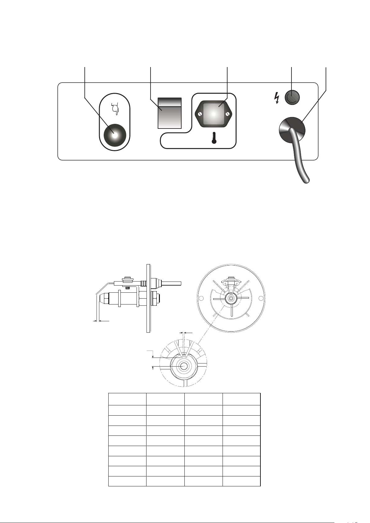
Models
Modelle
XYZ
EC100 2 mm 3 mm 6,5 mm
EC100 PT 2 m
m 3 mm 6,5 mm
EC200 4 m
m 2,5 mm 4 mm
EC300 4 m
m 2,5 mm 4 mm
GE250 2 m
m 3 mm 6,5 mm
GE360 2 m
m 3 mm 6,5 mm
GE400 2 m
m 3 mm 6,5 mm
GE600 2 m
m 3 mm 6,5 mm
CONTROL BOARD
TABLEAU DE COMMANDE
1 4
1 BOUTON REARMEMENT AVEC LAMPE TEMOIN
RESET BUTTON WITH CONTROL LAMP
2 LAMPE TEMOIN D’ALIMENTATION
CONTROL LAMP
3 INTERRUPTEUR MARCHE-ARRET
MAIN SWITCH
REGLAGE DES ELECTRODES
REGULATION OF ELECTRODES
3 2
4 PRISE THERMOSTAT D’AMBIANCE
ROOM THERMOSTAT PLUG
5 CABLE ELECTRIQUE
POWER CORD
5
3

IMPORTANT
Before using the heater, read and understand all instructions and follow them carefully. The manufacturer is not responsible for
damages to goods or persons due to improper use of units.
GENERAL RECOMMENDATIONS
The hot air heaters run on heating oil. Those with direct combustion send hot air and the combustion products into the room, while
those with indirect combustion are fitted with a flue to take the products of combustion away through the chimney.
Always follow local ordinances and codes when using this heater:
• Read and follow this owner’s manual before using the heater;
• THE INSTALLATION OF THE UNIT SHALL BE IN ACCORDANCE
WITH THE REGULATIONS OF THE AUTHORITIES HAVING JURISDICTION. Also, as a recommended installation practice reference
should be made to the current issue of CSA B139, Installation
Code for Oil Burning Equipment in Canada and NFPA 31 Standard
for the Installation of Oil-Burning Equipment in the USA;
• Use only in places free of flammable vapours or high dust content;
• Never use heater in immediate proximity of flammable materials
(the minimum distance must be 2 m);
• Make sure fire fighting equipment is readily available;
• Make sure sufficient fresh outside air is provided according to
the heater requirements. Direct combustion heaters should only
be used in well vented areas in order to avoid carbon monoxide
poisoning;
• A rough estimate of opening required for each gallon (US) of capacity is one square foot for indirect-fired heater and three
square foot at heater level, for direct-fired heaters;
• he heater is installed near a chimney to vent products of combustion (see the paragraph “CHIMNEY LAY-OUT RECOMMENDATION”) and connected to an electrical switchboard;
• When the heater is connected to a flue pipe, the flue pipe shall
terminate in a vertical section at least two feet long and sufficient
draft shall be created to assure safe and proper operation of the
heater;
• Never block air inlet (rear) or air outlet (front);
• In case of very low temperatures add kerosene to the heating oil;
• Connect the power cord to the mains and wait 15 min at least be
fore starting heater, to allow pre-heated filter warming heating oil
inside the filter;
• Make sure heater is always under surveillance and keep children
and animals away from it;
• Before starting the heater always check free rotation of ventilator;
• Indirect fired units only can be connected to air ducts to distribute warm air, with respect to the max. static pressure declared
(see “TECHNICAL SPECIFICATION” sheet);
• Unplug heater when not in use.
OPERATION
Before any attempt of starting the heater is made, check that your
electrical supply conforms to the data on the model plate.
Warning
Mains must be fitted with a thermo-magnetic differrential switch.
Unit plug must be link ed to a so cke t wit h a m ain s
switch.
Should the heater not start, check that oil tank is full and depress
reset button (1).
Should the heater still not work, please refer to chapter “OB-
SERVED FAULTS, CAUSES AND REMEDIES”.
STOPPING THE HEATER
Set main switch (3) on “0” position or turn thermostat or other
control device on lowest setting.
The flame goes out and the fan continues to work for approx. 90
sec. cooling the combustion chamber.
SAFETY DEVICES
The unit is fitted with an electronic flame control box. In case of
malfunction this box will cut in and stop the heater, at the same time
the pilot lamp in the control box reset button (1) will light up.
Heaters are also equipped with an overheat thermostat safety cut
out which will stop the heater in case of overheating. This thermostat
will reset automatically but you will have to depress button (1) on control box before being able to restart the heater.
TRANSPORT
Warning
Before making any attempt to restart heater find and
eliminate reason of overheating.
Before heater is moved it must be stopped and unplugged. Before
moving the heater wait till it has totally cooled off and make sure oil
tank cap is securely fixed.
The hot air heaters with wheels must be wheeled. The suspended
version which has no wheels must be transported with adequate machinery.
MAINTENANCE
Preventive and regular maintenance will ensure a long trouble free
life to your heater.
Warning
Never service heater while it is plugged in, operating or hot.
Severe burns or electrical shock can occur.
Every 50 hours of operation: disassemble filter and wash with
clean oil, remove upper body parts and clean inside and ventilator with
compressed air, check correct attachment of H.T. connectors to the
electrodes and check H.T. cables, remove burner assembly, clean and
check electrode settings, adjust according to scheme “REGULATION
OF ELECTRODES”.
GB
The heater can only work automatically when a control device,
such as for example a thermostat or a timer, is connected to the generator. Connection to the heater is made by removing the socket cover
(4) and inserting the thermostat plug.
To start the machine you must:
• if connected to the thermostat, turn the switch to (ON + );
• if not connected to the thermostat, turn the switch to (ON).
When unit is started for the first time or is started after the oil tank
has been totally emptied, the flow of oil to the burner may be impaired
by air in the circuit. In this case the control box will cut out the heater
and it might be necessary to renew the starting procedure once or
twice by depressing the reset button (1).
3
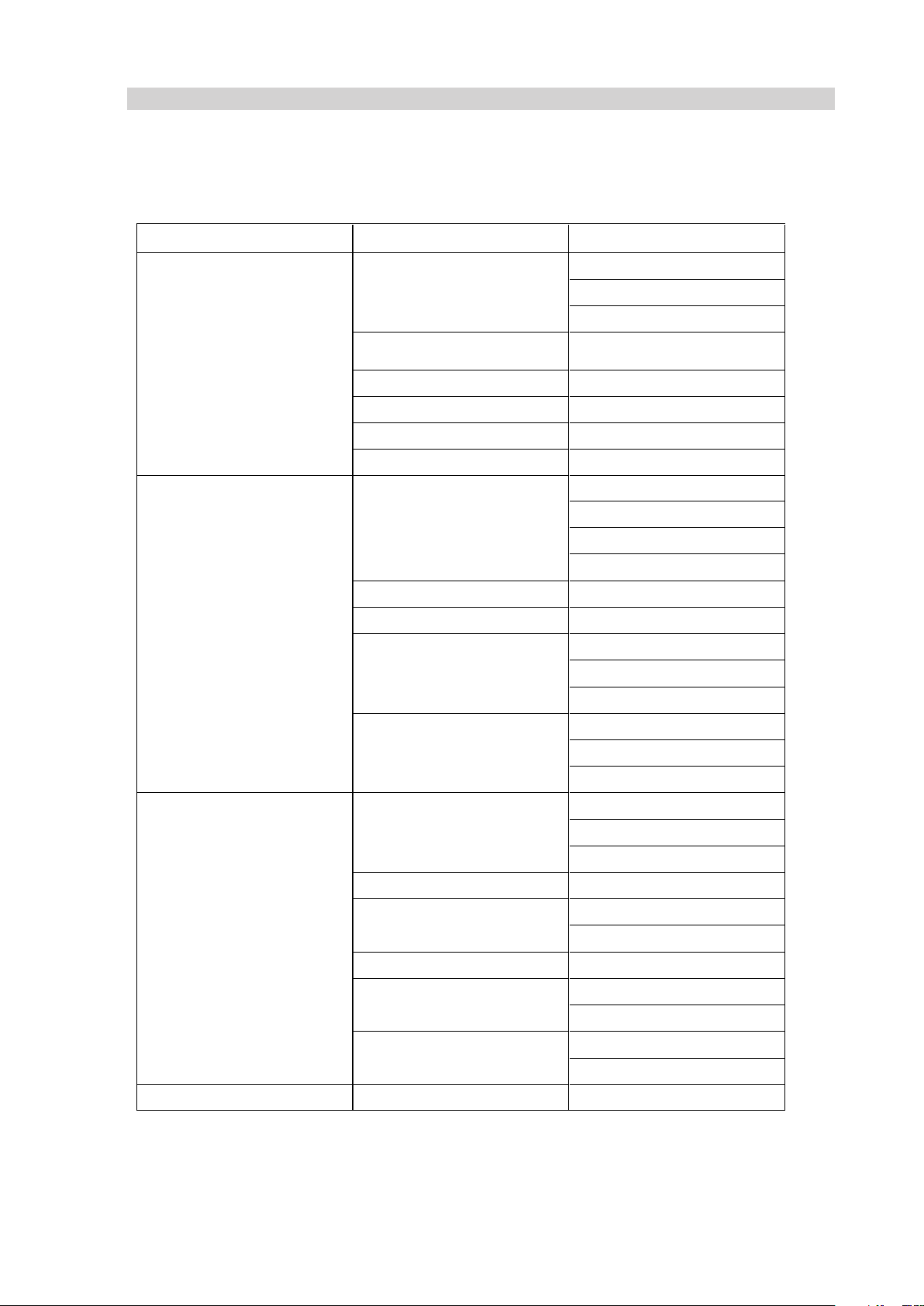
OBSERVED FAULT CAUSE REMEDY
• Check mains
•
Check
proper positioning and functioning of
• s
wi
t
ch
•
Chec
k fuse
•
Wrong setting of room thermostat or other
• c
ontrol
•
Check correct setting of heater control.
•
If thermo
st
at, make sure selected temperature
• i
s higher than room temperature
• Thermostat or other control defective • Replace control device
•
Electrical motor defective • Replace electrical motor
•
Ele
ct
rical motor bearings defective • Replace electrical motor bearings
•
Burned out c
ondenser • Replace condenser
•
Check connection of H.T. Ieads to electrodes
•
and transformer
• Check electrodes setting (see scheme
•
“REGULATION OF ELECTRODES”)
•
Chec
k
el
ec
trodes
for cleanliness
•
Replace H.T. transformer
•
Flame control box defective • Replace control box
•
Photoc
el
l
defective • Clean or replace photocell
•
Chec
k
s
tate of motor-pump plastic coupling
•
Check fuel line system including fuel filter for
• pos
s
ible leaks
• Clean or replace oil nozzle
•
Chec
k
el
ec
trical connection
• Check thermostat LI
• Clean or replace solenoid
• Make sure air inlet and outlet are free
• Check setting of combustion air flap
• Clean burner disc
• Too much combustion air • Check setting of combustion air flap
•
Drain fuel in tank with clean fuel
•
Cl
ean oi
l
fi
lter
•
Ai
r l
eaks in fuel circuit • Check the seals on the ducts and the diesel filter
•
Chec
k
pump pressure
• Clean or replace fuel nozzle
• Check pump pressure
• Replace nozzle
• Heater does not stop • Solenoid defective • Replace solenoid coil or complete solenoid
If heater s
till not working properly, please revert to nearest authorized dealer.
•
Not enough com
bustion air
•
Fuel contaminated or contains water
•
Not enough fuel at burner
• Too much fuel at burner
•
M
otor starts, heater emits smoke
•
No electrical current
• Motor does not start, no ignition
•
Electric ignitor defective
•
Not enough or no fuel at all at burner
•
M
otor starts, no ignition or cuts out
•
Solenoid defective
GB
OBSERVED FAULTS, CAUSES AND REMEDIES
4
 Loading...