

Page 1
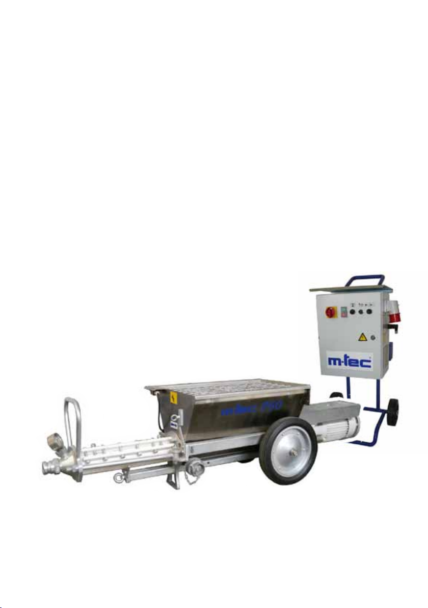
Operating instructions
Pump
P50
400V 50Hz 3ph
392425 - 2011-09
Page 2

2 P50
© 2011 m-tec mathis technik gmbh
The copyright on these operating instructions is owned by m-tec mathis technik gmbh. These operating instructions
are intended for assembly, operating, and maintenance personnel and contain regulations and drawings of a technical character that may not, wholly or in part, be duplicated, distributed, utilised for competitive purposes, or rendered
accessible to third parties without the explicit prior consent of the copyright holder.
Progress of technology
The manufacturer reserves the right to modify the specications to the respective state of progress without specic
prior notice. m-tec will be pleased to provide information on the current status of and any changes or additions to
these operating instructions.
392425 - 2011-09
Page 3

3
Dear Customer,
This machine complies with the state of the art and the generally applicable
standards and EC Directives. This can be seen from the CE label and the
annexed declaration of conformity. This can be found in the pocket on the device.
Please take the declaration of conformity out of the pocket before
commissioning and keep this in a safe place.
Also, please complete this page before commissioning the machine. By doing
so, you will be familiarising yourself with the key machine data that you can then
consult immediately without having to inspect the ratings plate. Moreover we ask
you to keep this page of data at hand when you contact us with any questions
about this machine. The data you must enter can be found on your machine’s
rating plate.
Type ....................................................
Machine no. ....................................................
392425 - 2011-09
Year built ....................................................
Power rating ....................................................
Current consumption
(total) ....................................................
Commissioned on ....................................................
Use ....................................................
Page 4

4 P50
Table of contents
1 Safety ........................................................................................................ 6
1.2 Danger symbols ......................................................................................... 7
1.3 Work safety ................................................................................................ 8
1.4 Personal protective equipment ................................................................ 11
2 Description ............................................................................................. 12
2.1 Intended application ................................................................................. 12
2.2 Application and operating principles ........................................................ 12
2.3 Machine overview .................................................................................... 14
2.4 Controls ...................................................................................................20
2.5 Technical data .......................................................................................... 22
2.6 Symbols on the machine ......................................................................... 24
3 Transport ................................................................................................26
4 Siting ....................................................................................................... 27
5 Startup ....................................................................................................28
5.1 Installing the conveying screw ................................................................. 28
5.2 Installing the worm pump ......................................................................... 30
5.3 Connecting the mortar hoses (optional) ................................................... 31
5.4 Connecting the remote control (optional) ................................................. 32
5.5 Connecting the wet material probe (optional) .......................................... 32
5.6 Connecting the air ttings (optional) ........................................................ 32
5.7 Connecting the compressor (optional) ..................................................... 32
5.8 Connecting the agitator (optional) ............................................................ 33
5.9 Connecting the power supply .................................................................. 33
5.10 Purging the hoses with slurry ................................................................... 34
6 Operation ................................................................................................ 35
6.1 Charging the machine with a continuous mixer ....................................... 36
6.2 Pumps ......................................................................................................36
6.3 Spraying (optional) ................................................................................... 38
6.4 Work breaks ............................................................................................. 40
6.5 Cleaning the wet material probe .............................................................. 40
6.6 Removing clogging .................................................................................. 40
6.7 End of operations .....................................................................................41
392425 - 2011-09
Page 5

Table of contents 5
7 Cleaning ..................................................................................................42
7.1 Cleaning the mortar hoses ....................................................................... 42
7.2 Cleaning the machine .............................................................................. 43
8 Troubleshooting .....................................................................................44
8.1 Malfunctions before startup ..................................................................... 44
8.2 Malfunctions during operations ................................................................ 45
9 Maintenance ........................................................................................... 46
9.1 Regular maintenance ............................................................................... 46
9.2 Oil changes .............................................................................................. 47
10 Spare parts and accessories ................................................................ 48
11 EC declaration of conformity ................................................................ 49
For circuit diagrams refer
392425 - 2011-09
to separate booklet
Page 6

6 P50
1 Safety
In these operating instructions the term “machine” is
always used for the combination of pump and switch
cabinet.
The machine has been built according to the state of the
art and has left the plant in perfect working order. Nevertheless, it can give rise to risks when it is used improperly or in violation of its design purpose or is operated
by untrained personnel.
For this reason, every user must read these instructions
carefully, in particular the section on safety, understand
them, and familiarise himself with the operation of the
machine before starting it up. Damage will therefore be
prevented, and the machine can be operated properly
and in accordance with its intended use. The operating
instructions for the m-tec pump P50 must be kept at the
machine at all times so that every user can inspect them
whenever necessary.
It is forbidden to make any changes to the machine.
The manufacturer will assume no liability for damages
caused by unauthorised conversions or modications to
the machine.
Only spare parts and accessories supplied by m-tec may
be used. If nonapproved spare parts and accessories are
used, m-tec will assume no liability for damage caused.
392425 - 2011-09
Page 7

Safety 7
1.2 Danger symbols
These operating instructions use the following symbols to
refer to potential risks.
WARNING
This symbol represents danger to life and limb. This
information must be observed with especial care. Also
ensure the safety of other persons near the machine and
its parts.
IMPORTANT
This symbol represents dangers to the machine and
materials. Observing this information prevents damage
to property.
CONTACT HAZARD
Warning of moving/rotating parts!
Do not reach into the machine when it is running!
Environment!
This symbol shows that provisions for the protection of
the environment must be observed.
392425 - 2011-09
INFO
This symbol points out additional information that may be
useful or helpful.
These operating instructions depict what to do as follows.
• Example copy only.
• Example copy only.
• Example copy only.
Page 8

8 P50
1.3 Work safety
When transporting, erecting, dismantling, operating, servicing, and cleaning the machine, the assigned persons
must observe the applicable national and international
industrial safety laws and regulations, also when these
are not named explicitly in these instructions.
All work must comply with the safety regulations for mortar pumping machines and mortar guns.
Observe in addition the following.
• The machine
- may be operated only for its design purpose and in compliance with the manufacturer’s operating instructions
- may be operated only by suitable, reliable persons who
are assigned by the company, who have been instructed
in the machine’s operation and maintenance, and who are
familiar with its processes
- must be sited stably on a at surface and secured against
unwanted movements
- must be sited outside of the danger area of elevated workplaces, or the workplace at the machine must be provided
with protective roong as a shield against falling objects
- (with frequency inverter) may be connected only to approved building site power distributors with ac/dc-sensitive
fault current circuit breakers (type B) for fault currents up
to 30 mA.
Before the machine is started up and when the motor is
running, check that the earth leakage circuit breaker functions correctly and without interference from the frequency
inverter.
- (without frequency inverter) may be connected only to approved building site power distributors with earth leakage
circuit breaker.
The fusing and connecting cables must comply with the
details in the specications (Section 2.5)!
392425 - 2011-09
Page 9

Safety 9
• The machine
- must be examined for conspicuous damage before every
startup.
Particular attention must be paid to the electrical conductors, water carrying lines, plug connectors, couplings, and
secure screw unions for the attached parts.
When damage is ascertained the machine may not be
operated until the damage has been properly repaired.
- must be inspected for safe operation by an expert in accordance with the legal provisions, but no less than once
a year.
Experts are persons that on the strength of their professional training and experience have acquired adequate
knowhow in the eld of mortar pumps and guns and are
familiar with the guidelines, generally accepted technical
procedures, and pertinent state regulations on industrial
safety and accident prevention to such an extent that they
are in a position to assess correctly whether the machine
is operating safely.
• The workplaces at the switch cabinet and around the pump
section must be easily accessible.
• Mortar hoses must be laid in such a manner that they cannot
kink or be damaged.
• During operations, the pressure may not exceed 40 bar.
mortar hoses used must exhibit a min operating overpressure
of 40 bar and a burst pressure of 120 bar.
hose pressure gauge that can measure the pressure in the
mortar hoses at all times.
We recommend a
• Unnecessary stress on the machine and high wearing on the
worm pump can be avoided when only as many hoses are
used as are actually needed.
The
392425 - 2011-09
Page 10

10 P50
• When the machine is started up, the mortar hoses must be
provided with adequate preliminary lubrication, the mortar
used must have good pumping properties, and there are no
leaks at the connecting sites.
• To prevent viscous materials from overloading the motor, set
the potentiometer to Level 5 (approx 25 Hz) before starting the machine with frequency inverter. Afterwards you can
raise the speed.
• Never direct the spray gun at persons!
• The pump may not run until empty if there is to be no dam-
age to the worm pump. It must be switched OFF as soon
as material is no longer being pumped!
• When switched OFF via remote control or the spray gun,
the machine is still in standby and can start up again at any
time via remote control or the spray gun.
Indicator: the white indicator lamp lights up at the dual
pushbutton.
Also leaking air hoses or damaged remote control cables
can cause the machine to start up again.
Hoses and cables must be inspected at regular intervals.
There may be an uncontrolled discharge of material from
the spray head!
• Blockages must be removed in accordance with the details
in the operating instructions. The persons assigned to
remove blockages must position themselves so that they
cannot be hit by discharging mortar. There may be no other
persons in the vicinity.
• Mortar hoses may be disconnected only when they are
unpressurised. The pressure can be read off at the hose
pressure gauge.
Suitable goggles must be worn when hoses are detached.
Cover mortar hose couplings with a plastic sheet, and open
carefully with your face turned away.
392425 - 2011-09
Page 11

Safety 11
• When the safety installations on the machine trigger or fail,
operations must be suspended until the fault has been remedied.
• Before all maintenance work on the machine, pull out the
mains plug: even when the machine is switched off, certain
parts are still conducting.
• The troubleshooting table is not intended to replace the
detailed instructions in the relevant sections. Observe the
safety instructions in the relevant sections!
• The compressor and pressure vessel are subject to the
applicable national test conditions and accident prevention
regulations.
• Before transport remove all residue out of the machine’s
mortar hopper.
• Use load retention means (e.g. cables, belts) designed for
min 750 kg.
• It is forbidden to make any changes to the machine.
Only spare parts and accessories supplied by m-tec may be
used. If nonapproved spare parts and accessories are used,
m-tec will assume no liability for damage caused.
1.4 Personal protective equipment
• The company must provide its personnel with suitable per-
sonal equipment for noise protection when the noise rating
level at the workplace exceeds 80 dB(A). Employees must
use these when the noise rating level exceeds 85 dB(A).
• Suitable goggles must be worn during spraying work and
when blockages are being removed. Suitable goggles
consist of a frame complying e.g. with DIN 58211 Part 2 and
safety lenses complying e.g. with DIN 4647 Sheet 5.
• Spraying work requires in addition suitable protection for the
head and feet.
392425 - 2011-09
Page 12

12 P50
2 Description
2.1 Intended application
The intended use of the P50 consists in the pumping of previously mixed, pumpable materials like bricklaying mortar, slot-
ted mortar, decorative renders, and llers with a max grain
size of 8 mm.
Using the P50 for any other purpose poses a danger to
the life and limb of the user or of damage to the machine
and other assets and may jeopardise the machine’s oper-
ating efciency.
2.2 Application and operating principles
The P50 is a universal pump for materials that can be mixed
in a machine.
The dry material is rst mixed in a separate continuous mixer
and emptied into the pump’s hopper. There, the material is
additionally mixed by a specially designed conveying screw
that transports it to the worm pump and from there to the
processing site.
Hoppers with a capacity of 90 l and 120 l are available for
this pump.
When the pump is tted with a 120 l hopper, an additional
agitator can be installed for the optimal mixing of viscous
materials.
The pump can be operated from various workplaces, either
directly at the pump’s switch cabinet (e.g. for starting up or
cleaning) or from a more distant workplace at the remote
control or spray gun.
392425 - 2011-09
Page 13

Description 13
The material supply can be regulated automatically with a wet
material probe.
The wet material probe monitors the level in the pump’s hopper
and regulates the upstream continuous mixer. It is connected
to the mixer’s switch cabinet. The continuous mixer is switched
OFF automatically when the max level is reached in the pump.
When the level falls, the probe switches the continuous mixer
back ON.
For the spraying process, the machine must be tted in addition with a compressor, air ttings, and a spray gun.
The compressor supplies the compressed air needed for the
spraying process. The machine is regulated by the spray gun
in conjunction with the pressure controller.
Depending on the conguration, the machine is tted with either
a 90 l or a 120 l hopper and a switch cabinet with or without
frequency inverter.
392425 - 2011-09
Page 14
14 P50
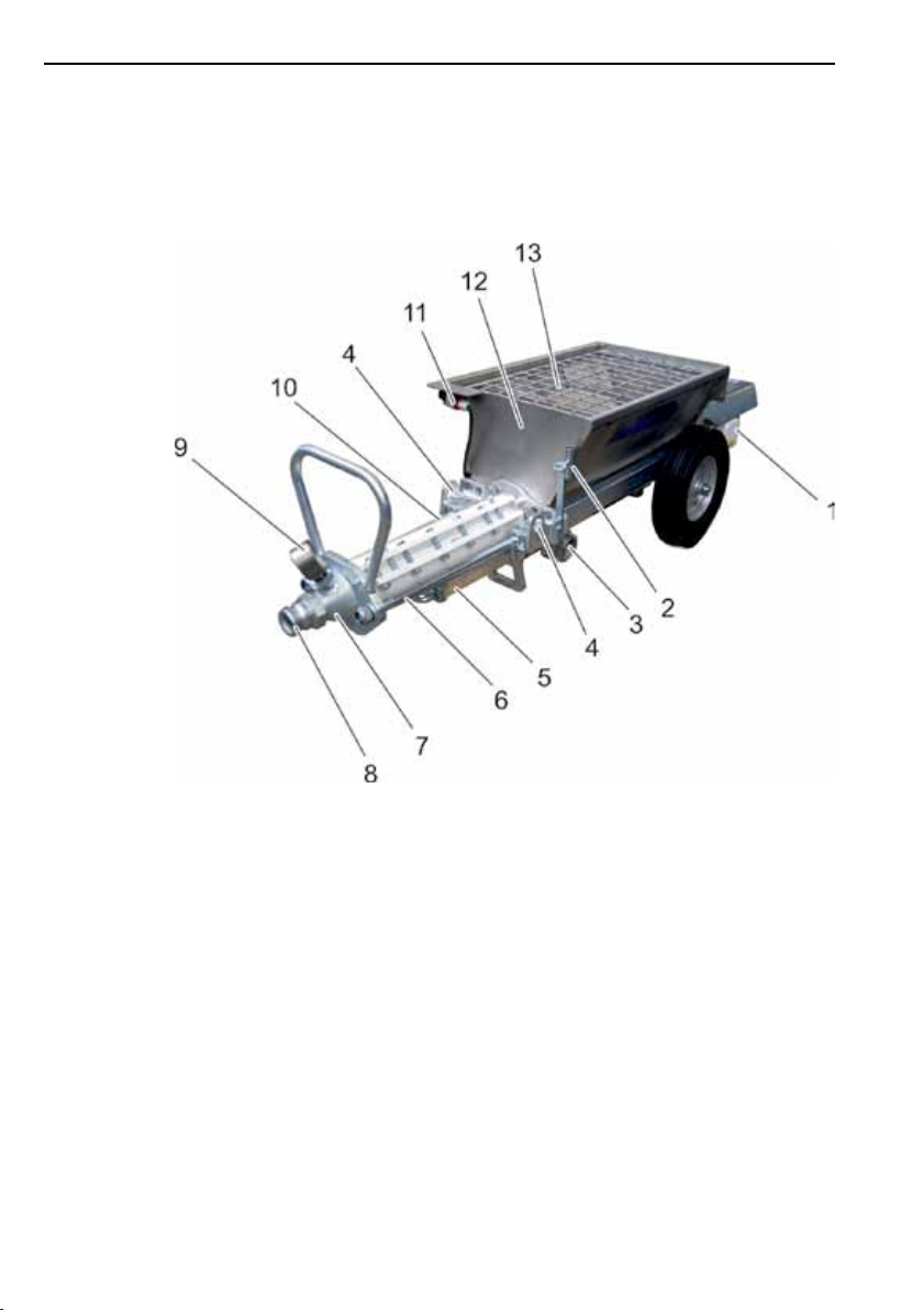
2.3 Machine overview
2.3.1 Pump with 90 l hopper
Fig 1 – View of pump
1 Pump motor
2 Probe bracket (optional)
3 Emptying nozzle
4 Transport eye
5 Worm pump mount
6 Connecting rod
7 Pump end piece
8 Mortar hose coupling
9 Hose pressure gauge (optional)
10 Worm pump
(stator with screw-in rotor)
11 Safety switch
12 90 l hopper
13 Screen
392425 - 2011-09
Page 15
Description 15
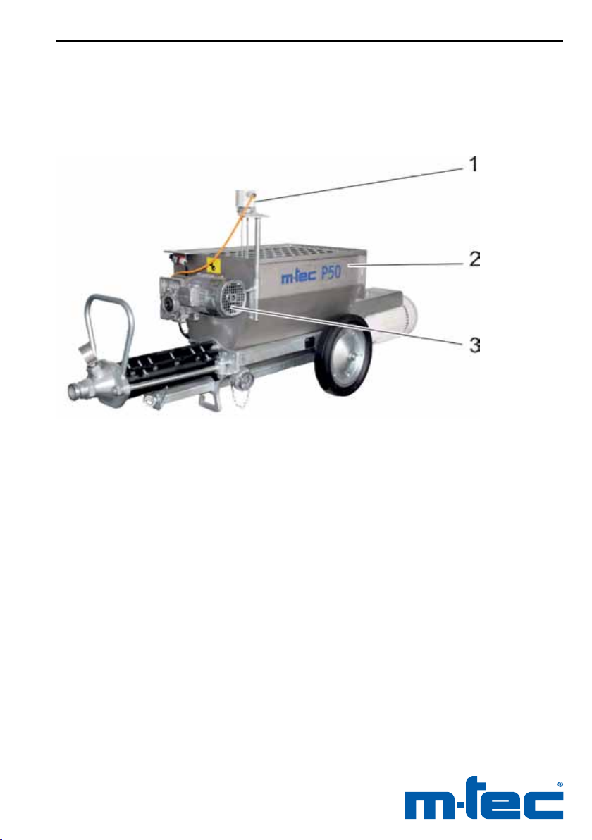
2.3.2 Pump with 120 l hopper and agitator
392425 - 2011-09
Fig 2 – View of pump with 120 l hopper and agitator
1 Wet material probe (optional)
2 120 l hopper
3 Drive for agitator (optional)
Page 16
16 P50
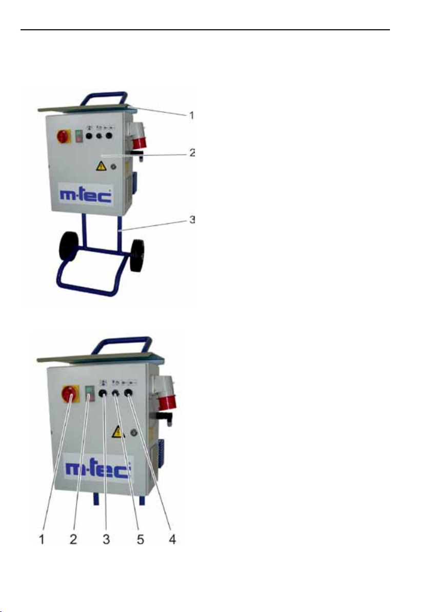
2.3.3 Switch cabinet at the stand frame (version with frequency inverter)
Fig 3 – Switch cabinet with frequency
inverter at the stand frame
1 Protective cover
2 Switch cabinet
3 Frame on wheels
Fig 4 – Front side
1 Main switch
2 Dual pushbutton
3 Selector switch for motor’s rotation direction
4 ON/OFF switch for agitator
5 Potentiometer
392425 - 2011-09
Page 17
Description 17
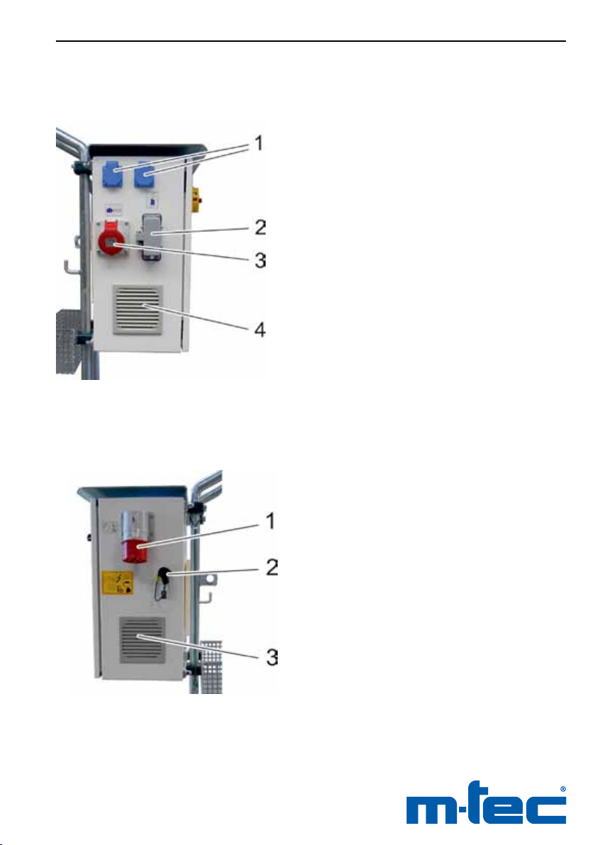
Fig 5 – Left side
1 Safety sockets
2 Pump connection
3 Agitator connection
4 Ventilation grille
392425 - 2011-09
Fig 6 – Right side
1 Input plug
2 Remote control connection
3 Ventilation grille
Page 18
18 P50
2.3.4 Switch cabinet without frequency inverter
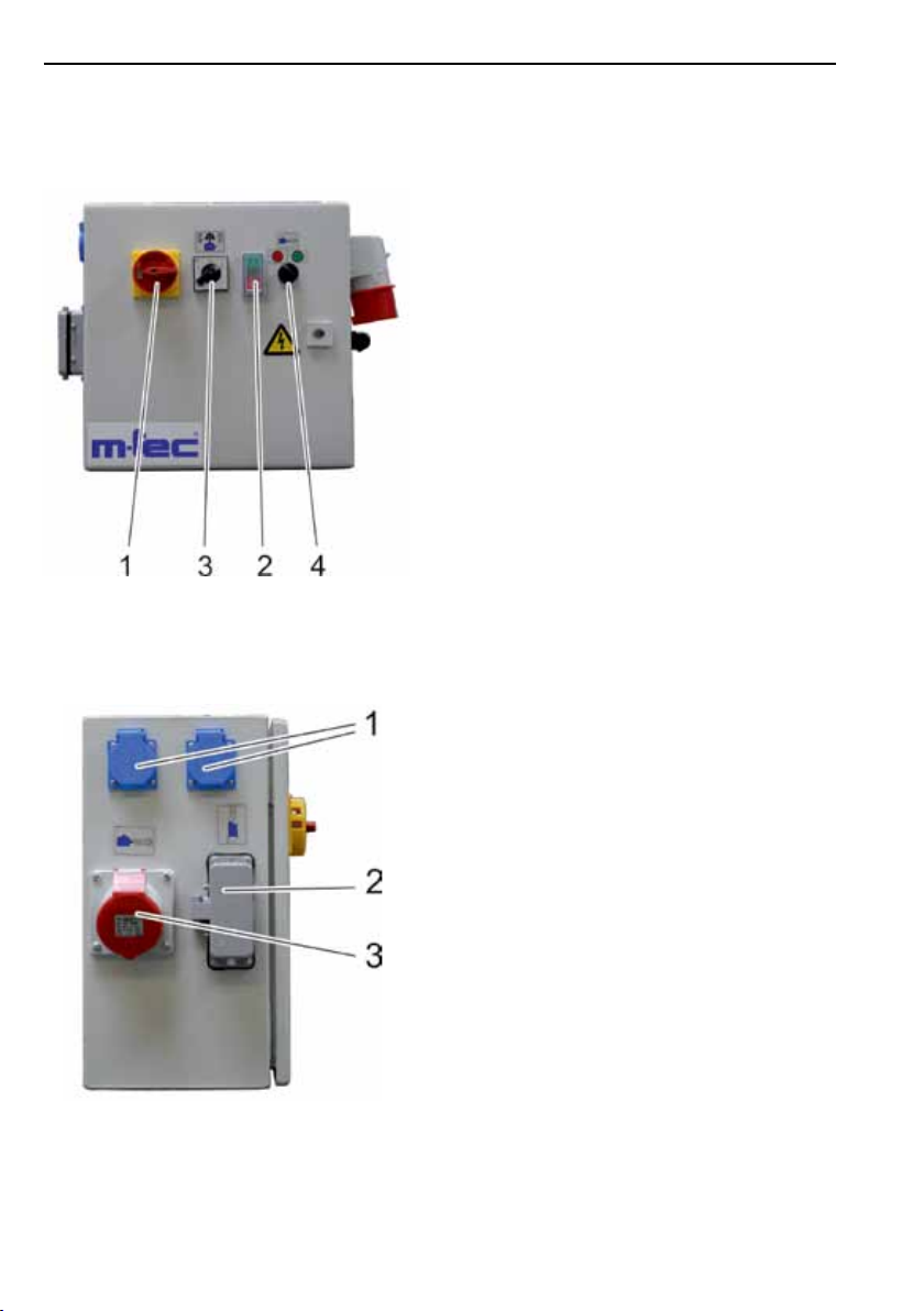
Fig 7 – Front side
1 Main switch
2 Dual pushbutton
3 Selector switch for motor’s rotation direction
4 ON/OFF switch for agitator
Fig 8 – Left side
1 Safety sockets
2 Pump connection
3 Agitator connection 16A 5 pin 6h or
compressor connection 16A 4 pin 6h
392425 - 2011-09
Page 19
Description 19
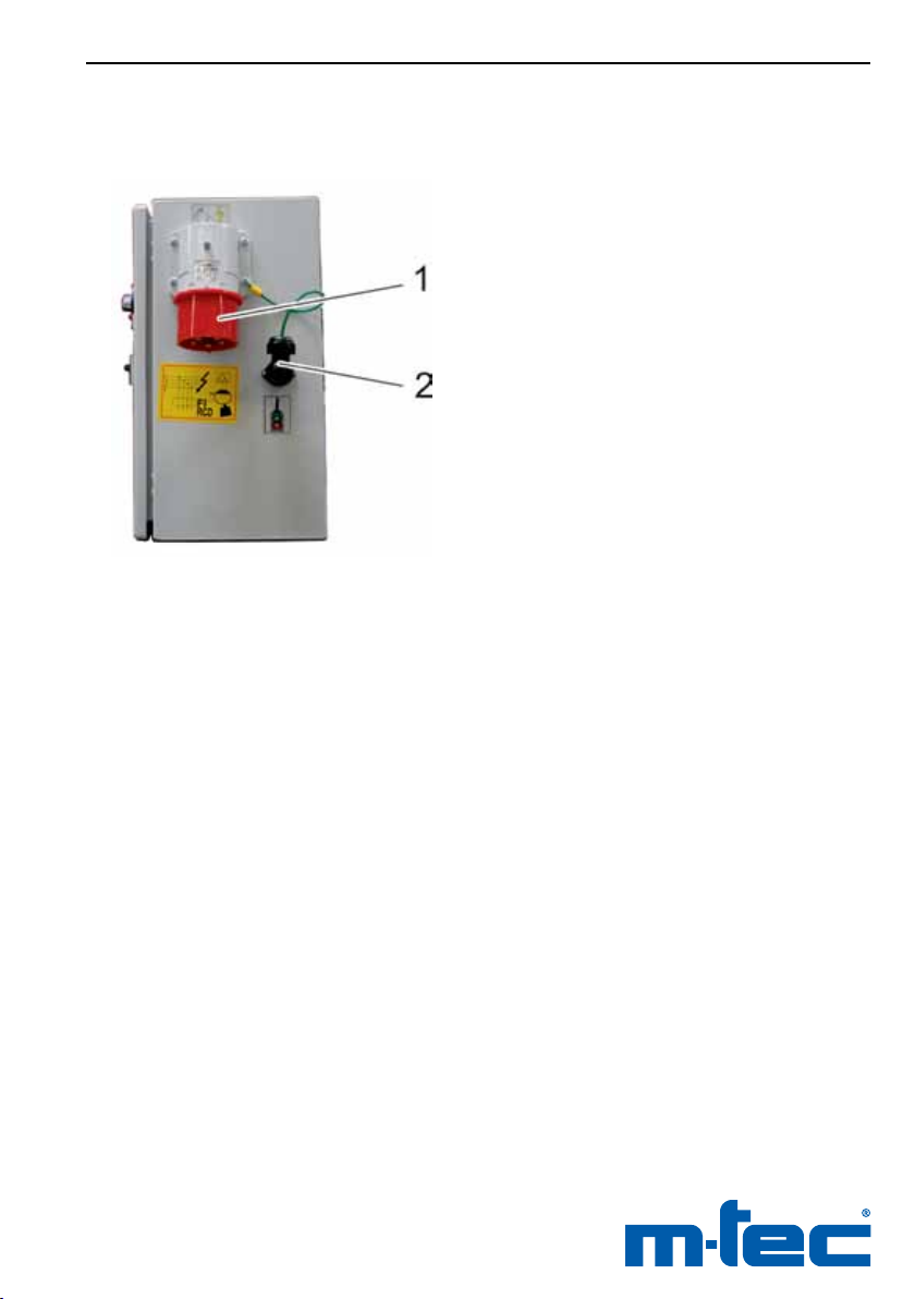
Fig 9 – Right side
1 Input plug
2 Remote control connection
392425 - 2011-09
Page 20

20 P50
2.4 Controls
The electrical equipment complies with the VDE regulations
and is installed in a maintenance friendly housing.
Main switch (Fig 4 + 7, no. 1)
The supply voltage is switched ON and OFF at the main
switch.
At the position “I” the machine is in standby mode.
Also in the deactivated state there is voltage applied up
to the main switch!
Dual pushbutton (Fig 4 + 7, no. 2)
This button serves to start and stop the machine when the
main switch is at ON.
green = START
red = STOP
When the machine is switched ON and ready to operate, the
white signal lamp on the dual pushbutton lights up.
Selector switch for motor’s rotation direction (
no. 3)
This switch sets the rotation direction of the pump motor:
Switch position at the switch cabinet with frequency inverter:
Fig 4 + 7
,
- Left: Backwards for depressurising the mortar
hoses (jog mode only)
- Centre: Motor stationary
- Right: Pump mode
Switch position at the switch cabinet without frequency inverter:
- Centre: Motor stationary
- The motor’s rotation direction at the left and right switch
positions depends on the input eld and must be checked
before every startup (see Section 5.7.2).
392425 - 2011-09
Page 21

Description 21
Selector switch for agitator (Fig 4 + 7, no. 4, optional)
This switch switches ON and OFF the agitator.
Switch position:
- Left: Agitator is switched OFF
- Right: Agitator is switched ON
Potentiometer (Fig 4, no. 5, only at switch cabinet with
frequency inverter)
The potentiometer can be used to adjust the pump motor
speed continuously from 5 to 50 Hz.
Wet material probe (Fig 2, no. 1, optional)
The wet material probe monitors the level in the pump’s hopper and regulates the upstream continuous mixer. It is connected to the mixer’s switch cabinet.
392425 - 2011-09
Page 22

22 P50
2.5 Technical data
Measurements and weights of pump
Dimensions 5.5 kW 7.5 kW 9.2 kW
Length
– 90 l hopper
– 120 l hopper
Width
– 90 l hopper
– 120 l hopper
Height
– 90 l hopper
– 120 l hopper
Hopper volume
– 90 l hopper
– 120 l hopper
Weight
– 90 l hopper
– 120 l hopper
Noise levels 70 dB(A); sound pressure level at 1 m distance,
2095 mm
--
596 mm
--
576 mm
--
90 l
--
approx 200 kg
--
free eld measurement during operation
2053 mm
2053 mm
596 mm
596 mm
576 mm
705 mm
90 l
120 l
approx 220 kg
approx 230 kg
2147 mm
2147 mm
596 mm
596 mm
585 mm
705 mm
90 l
120 l
approx 260 kg
approx 290 kg
Measurements and weights of switch cabinet at the stand frame
Dimensions
Length x width x height approx 495 x 560 x 1095mm
Weight approx 30–51 kg
392425 - 2011-09
Page 23

Description 23
Electrical connection
Motor
5.5 kW 7.5 kW 9.2 kW
400V 50 Hz 3 ph
Voltage 400 V 3 ph 400 V 3 ph 400 V 3 ph
Frequency
– without frequency
inverter
– with frequency inverter
50 Hz
--
50 Hz
5–50 Hz
50 Hz
5–50 Hz
Power 5.5 kW 7.5 kW 9.2 kW
Input current See ratings plate
Speed
– without frequency
inverter
– with frequency inverter
168 rpm
--
160 rpm
16–160 rpm
162/234 rpm
16–162 rpm
24–234 rpm
Connection
Switch cabinet with frequency inverter:
via ac/dc-sensitive fault current circuit breakers (type B) for fault
currents up to 30 mA, fusing min 32 A, supply line 5 x 4 mm
Switch cabinet without frequency inverter:
via earth leakage circuit breaker,
fusing min 32 A, supply line 5 x 4 mm
2
Agitator (optional)
Power -- 1.1 kW
Speed -- 200 rpm
2
392425 - 2011-09
Page 24

24 P50
Conveying output*
Conveying pressure max 30 bar max 40 bar max 40 bar
Output
Plaster
90 l hopper
120 l hopper
Flowing screed
90 l hopper
120 l hopper
Concrete
90 l hopper
120 l hopper
Conveying height max 30 m max 30 m max 30 m
Conveying distance max 80 m max 80 m max 80 m
* Output, conveying distance, and conveying height depend on the conveyed
material and the condition of the used rotor and stator.
5.5 kW 7.5 kW 9.2 kW
max 30 l/min
--
-- max 100 l/min
-- max 80 l/min
--
--
max 100 l/min
max 80 l/min
--
--
max 100 l/min
max 145 l/min
max 80 l/min
--
2.6 Symbols on the machine
Operate only via earth
leakage circuit breaker
IMPORTANT
Do not reach into the
machine when it is
running!
Voltage
Selector switch
motor’s rotation
direction
Input plugIMPORTANT
Potentiometer
motor speed
392425 - 2011-09
Page 25

Description 25
Connection
worm pump
Load suspension
points
Only when (optional) spray gun is used
Connection
compressor
Connection
remote control
Rotation direction
arrow
Connection
spray gun
Agitator OFF Agitator ON
Place where these
operating instructions
are kept
Air pressure controller
392425 - 2011-09
Page 26

26 P50
3 Transport
Heed the following when transporting the machine with a
crane or similar hoisting gear on oors or trucks.
Before transport remove all residue out of the machine’s
mortar hopper.
Make sure that all connecting cables have been detached
at the switch cabinet (power supply, pump, probes, remote control, etc.).
Use load retention means (e.g. cables, belts) designed
for min 750 kg, and secure these only to the provided
suspension points.
• Secure the belts to the load suspension points on the ma-
chine (see Fig 1, no. 4).
• Secure the belts to the grip on the switch cabinet’s stand
frame.
392425 - 2011-09
Page 27

Transport / Siting 27
4 Siting
The machine must be sited stably on a at surface and
secured against unwanted movements.
The machine must be sited outside of the danger area
of elevated workplaces, or the workplace at the machine
must be provided with protective roong as a shield
against falling objects.
The workplaces at the switch cabinet and around the
pump section must be easily accessible.
392425 - 2011-09
Page 28

28 P50
5 Startup
When transporting, erecting, dismantling, operating, servicing, and cleaning the machine, the assigned persons
must observe the applicable national and international
industrial safety laws and regulations, also when these
are not named explicitly in these instructions.
The machine must be examined for conspicuous damage
before every startup.
Particular attention must be given to the electrical lines,
water carrying conduits, plugs, couplings, and the screw
unions on all mounted parts.
When damage has been ascertained, the machine may
not be operated until the damage has been properly
eliminated.
Perform the work in the order specied here. Under no
circumstances must the power supply be connected
before any of the preceding steps!
5.1 Installing the conveying screw
• Loosen the screw at the screen, and remove the screw,
washer, and mount from the hopper.
• Pull open the hinged screen.
• Insert the conveying screw (Fig 10, no. 2) through the
opening in the front of the hopper and into the motor coupling (Fig 10, no. 1).
• Close the hinged screen, and secure it in place with the
screw, washer, and mount.
392425 - 2011-09
Page 29
Startup 29
392425 - 2011-09
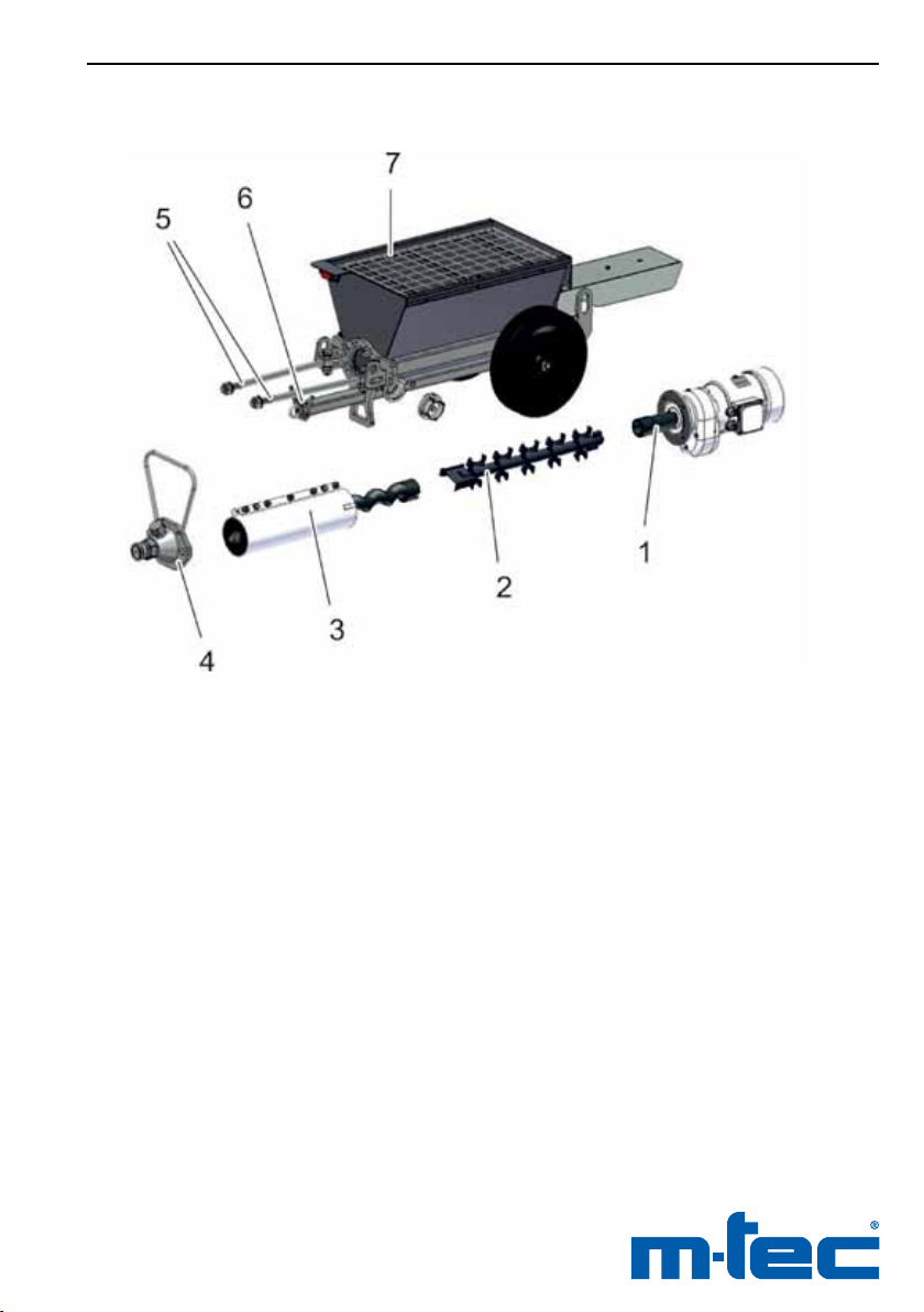
Fig 10 – Installing the conveying screw
and worm pump
1 Motor coupling
2 Conveying screw
3 Worm pump (stator with screw-in rotor)
4 Pump end piece with mortar hose coupling
5 Connecting rods
6 Worm pump mount
7 Screen
Page 30
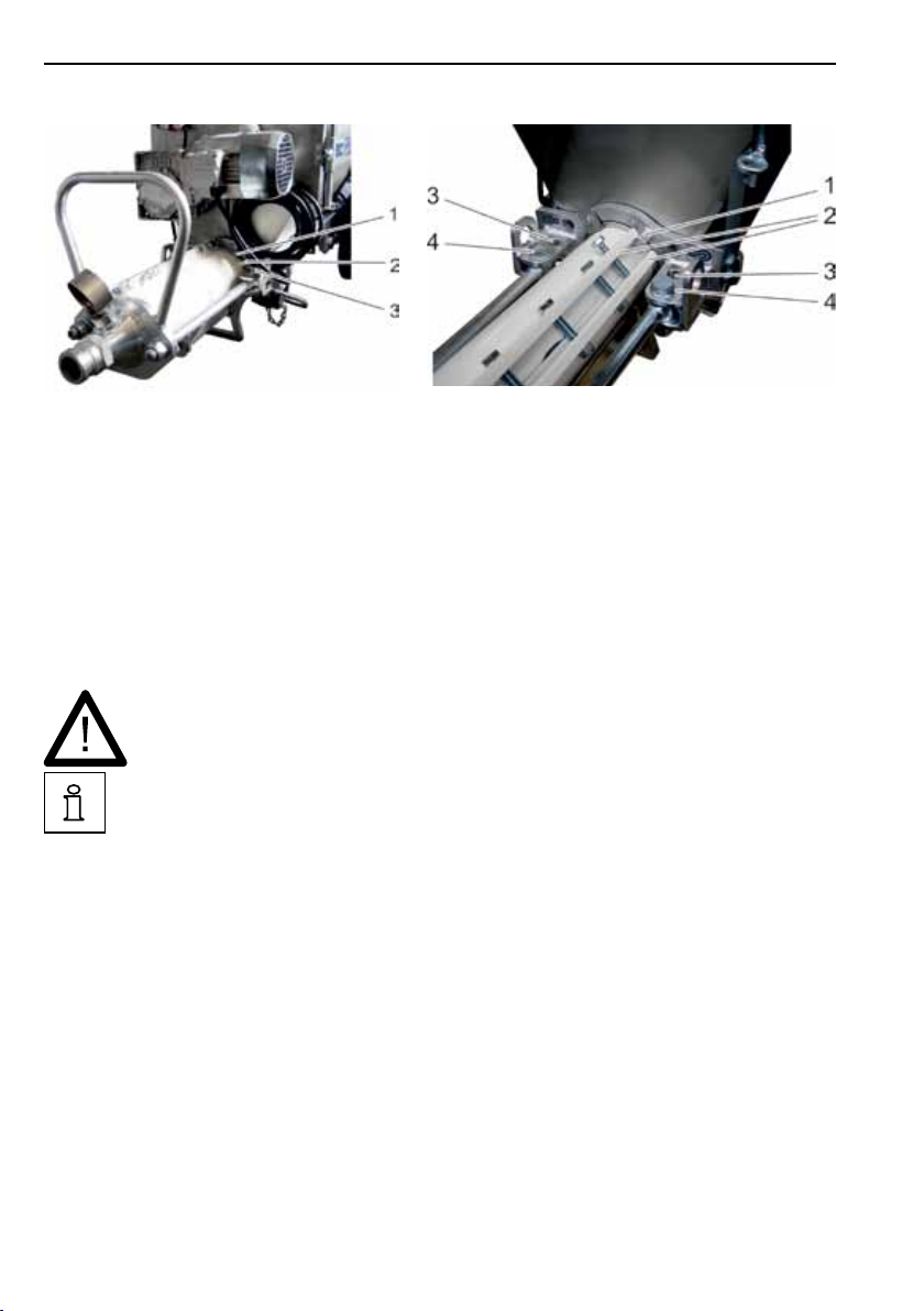
30 P50
Fig 11 – Installing the worm pump
with antitwist protection
1 Antitwist protection at hopper
2 Antitwist protection at stator
3 Screw union at rear of connecting rod
5.2 Installing the worm pump
When assembling, make sure that all ange faces are
clean at the pump end piece, worm pump, and hopper.
The frame presents two holes for securing the connecting
rods (Fig 12, no. 3 + 4). Which of these holes are used depends on the worm pump used.
– Stators approx 260 and 500 mm long:
rear hole
– Stators approx 540 mm long:
front hole
• Assemble the worm pump (rotor and stator, Fig 10, no. 3).
• Worm pump with antitwist protection (Fig 11)
Place the worm pump on its mount so that the stator’s
antitwist protection (Fig 11, no. 2) lies between the antitwist
protection on the frame and the screw union at the rear of
the connecting rod.
Fig 12 – Installing the worm pump
without antitwist protection
1 Antitwist protection at hopper
2 Clamping bars at stator
3 Rear hole for connecting rod
4 Front hole for connecting rod
392425 - 2011-09
Page 31

Startup 31
• Worm pump without antitwist protection (Fig 12)
Place the worm pump on its mount so that the antitwist
protection on the frame lies between the two clamping bars
on the stator.
• Position the pump end piece at the worm pump, insert both
connecting rods (Fig 6, no. 7) through the recesses in the
pump end piece, and secure them equally with their nuts.
• Make sure that all connections and mounted parts sit se-
curely.
5.3 Connecting the mortar hoses (optional)
The mortar hoses used must exhibit a min operating
overpressure of 40 bar and a burst pressure of 120 bar.
We recommend a hose pressure gauge that can measure
the pressure in the mortar hoses at all times.
Mortar hoses must be laid in such a manner that they
cannot kink or be damaged.
When the machine is started up, the mortar hoses must
be provided with adequate preliminary lubrication, the
mortar used must have good pumping properties, and
there are no leaks at the connecting sites.
Unnecessary stress on the machine and high wearing
on the worm pump can be avoided when only as many
hoses are used as are actually needed.
392425 - 2011-09
• The appropriate lengths of mortar hose must be laid when-
ever possible in a straight line from the machine to the
processing site and provided with reliable couplings.
• Connect the mortar hoses to the pump end piece.
Page 32

32 P50
5.4 Connecting the remote control (optional)
• Remove the dummy plug, and insert the remote control
cable in the switch cabinet (Fig 3, no. 1).
When switched OFF via remote control or the spray gun,
the machine is still in standby and can start up again at
any time via remote control or the spray gun. Indicator:
the white indicator lamp lights up at the dual pushbutton.
Also leaking air hoses or damaged remote control cables can cause the machine to start up again. Hoses and
cables must be inspected at regular intervals. There may
be an uncontrolled discharge of material from the spray
head!
5.5 Connecting the wet material probe (optional)
• Secure the wet material probe to the mounting provided on
the pump (see Fig 8, no. 7).
• Connect the probe cable to the switch cabinet for the con-
tinuous mixer.
5.6 Connectingtheairttings(optional)
The air ttings are needed only when the machine is used
for spraying. The steps for connecting the air ttings are
described in Section 6.3.
5.7 Connecting the compressor (optional)
A compressor is needed only when the machine is used for
spraying. The required steps are described in Section 6.3.
392425 - 2011-09
Page 33

Startup 33
5.8 Connecting the agitator (optional)
When the pump is tted with a 120 l hopper, an additional
agitator can be installed for the optimal mixing of viscous
materials.
• Connect the mains cable to the input plug.
5.9 Connecting the power supply
5.9.1 Switch cabinet with frequency inverter
The machine may be connected only to approved building site power distributors with ac/dc-sensitive fault
current circuit breakers (type B) for fault currents up to
30 mA.
Before the machine is started up and when the motor
is running, check that the earth leakage circuit breaker
functions correctly and without interference from the
frequency inverter.
The fusing and connecting cables must comply with the
details in the specications (Section 2.5)!
• Connect the mains cable to the input plug.
The frequency inverter ensures that the motor rotates in the
right direction.
5.9.2 Switch cabinet without frequency inverter
The machine may be connected only to approved building site power distributors with earth leakage circuit
breakers. The fusing and connecting cables must com-
ply with the details in the specications (Section 2.5)!
The motor’s rotation direction must be checked and if
necessary corrected before every startup!
• Connect the mains cable to the input plug.
• Set the main switch to “I”.
392425 - 2011-09
Page 34

34 P50
The next step checks the motor’s rotation direction. This
must correspond to the arrow on the hopper. When this
is not so, the machine must be switched OFF immediately at the dual pushbutton.
• Start the machine at the dual pushbutton, and check the
rotation direction of the pump motor. The fan’s rotation
direction must correspond to the arrow on the hopper.
• If this is not so, switch OFF the machine immediately at the
dual pushbutton.
• Change the motor’s rotation direction at the selector switch
“Motor rotation direction”.
5.10 Purging the hoses with slurry
Purging the hoses with slurry prior to regular operations minimises the risk of clogging.
Use anhydrite binding slurry when processing owing
screeds or mortar lime slurry when processing plasters.
• Fill the hopper with about 6 l of slurry.
• Set the main switch to “I”, and switch ON the machine at
the dual pushbutton.
• Let the machine run until the lime slurry has been pumped
out of the mortar hose, and then switch OFF the pump at
the dual pushbutton.
392425 - 2011-09
Page 35

Operation 35
6 Operation
When transporting, erecting, dismantling, operating, servicing, and cleaning the machine, the assigned persons
must observe the applicable national and international
industrial safety laws and regulations, also when these
are not named explicitly in these instructions.
The machine must be examined for conspicuous damage
before every startup.
Particular attention must be given to the electrical lines,
water carrying conduits, plugs, couplings, and the screw
unions on all mounted parts.
When damage has been ascertained, the machine may
not be operated until the damage has been properly
eliminated.
When switched OFF via remote control or the spray gun,
the machine is still in standby and can start up again at
any time via remote control or the spray gun. Indicator:
the white indicator lamp on the dual pushbutton lights up.
Also leaking air hoses or damaged remote control cables
can cause the machine to start up again.
Hoses and cables must be inspected at regular intervals.
There may be an uncontrolled discharge of material from
the spray head!
392425 - 2011-09
Make sure that the screen is secured rmly to the pump.
Do not reach into the hopper. Do not introduce any objects into the hopper!
Page 36

36 P50
6.1 Charging the machine with a continuous mixer
Observe the operating instructions for the mixer.
• Before charging the pump, set the material consistency at
the continuous mixer (see the operating instructions for the
mixer).
• Place the pump under the mixer’s discharge so that mate-
rial is fed to the front third of the hopper.
When a wet material probe is used to regulate the mixer:
• Secure the probe in the mounting provided for this purpose
on the pump’s hopper (see Fig 4).
• Connect the probe’s cable to the mixer’s switch cabinet.
6.2 Pumps
The pump may not run until empty if there is to be no
damage to the worm pump. It must be switched OFF as
soon as material is no longer being pumped!
392425 - 2011-09
Page 37

Operation 37
6.2.1 Switch cabinet with frequency inverter
To prevent viscous materials from overloading the
motor, set the potentiometer to Level 5 (approx 25 Hz)
before starting the machine. Afterwards you can raise
the speed.
Set the pump’s main switch to “I”.
• Switch ON the machine at the main switch.
When operating without remote control, the machine starts
and pumps the material to the processing site.
When operating with remote control, the machine must be
switched ON additionally at the remote control or cable drum
switch.
6.2.2 Switch cabinet without frequency inverter
The motor’s rotation direction must be checked and if
necessary corrected before every startup!
• Set the pump’s main switch to “I”.
• Switch ON the machine at the main switch.
When operating without remote control, the machine starts
and pumps the material to the processing site.
When operating with remote control, the machine must be
switched ON additionally at the remote control or cable drum
switch.
392425 - 2011-09
Page 38

38 P50
6.3 Spraying (optional)
Spraying is possible only with the optional compressor, air
ttings, and spray gun tted as additional equipment.
Never direct the spray gun at persons!
Make sure before switching ON the machine that the air
tap is closed on the spray gun.
When switched OFF via remote control or the spray gun,
the machine is still in standby and can start up again at
any time via remote control or the spray gun. Indicator:
the white indicator lamp lights up at the dual pushbutton.
Also leaking air hoses or damaged remote control cables can cause the machine to start up again. Hoses and
cables must be inspected at regular intervals. There may
be an uncontrolled discharge of material from the spray
head!
• Couple the spray gun’s air hose to the air ttings’ GEKA
coupling (Fig 14, no. 2).
• Couple the mortar hose to the spray gun (Fig 8, no. 2).
• Connect the air hose for the air ttings to the compressor
(Fig 8, no. 4).
• Connect the compressor’s mains cable to the switch cabi-
net (Fig 2, no. 6).
• On spray guns with pneumatic controller, connect the cable
for the air pressure controller (Fig 14, no. 3) to the switch
cabinet (Fig 3, no. 1).
On spray guns with electrical controller, connect the remote
control cable to the switch cabinet.
The machine can now be switched ON and OFF at the air tap
on the spray gun.
392425 - 2011-09
Page 39
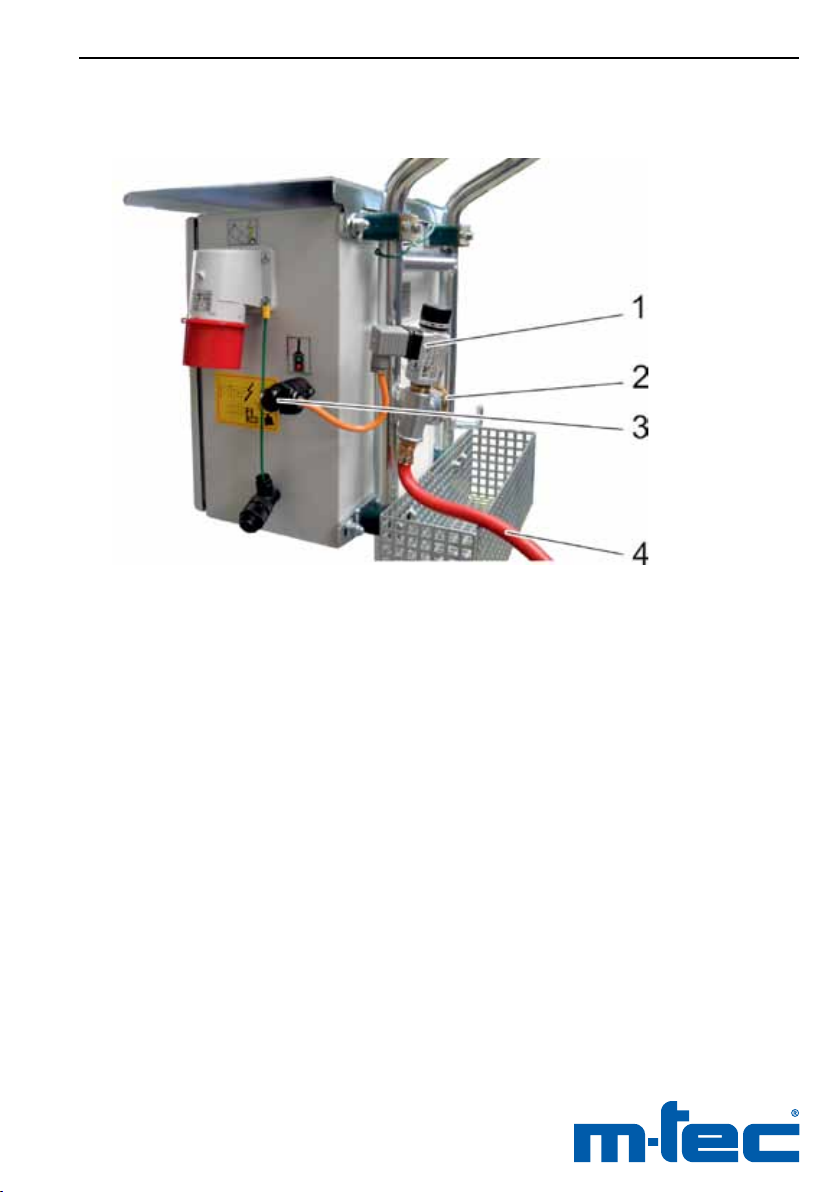
Operation 39
392425 - 2011-09
Fig 13 – Air ttings (optional)
1 Air pressure controller
2 GEKA coupling
3 Plug for air pressure controller
4 Air hose for connecting to compressor
Page 40

40 P50
6.4 Work breaks
During work breaks, the processed material’s setting
time must generally be observed!
• When work breaks exceed ten minutes, switch OFF the
machine at the dual pushbutton.
• At high outside temperatures or when work breaks are
longer than thirty minutes, pump the mortar hoses empty.
• Before even longer work breaks, also set the main switch
to “O”.
6.5 Cleaning the wet material probe
The probe should be cleaned of material deposits every
two to three working hours. When removing the contact
rod, make sure that there is no damage to its insulation.
6.6 Removing clogging
At the rst sign of clogging, the machine must be
switched OFF immediately at the dual pushbutton!
• Stop the material feed from the continuous mixer.
• Set the selector switch “Motor rotation direction” (Fig 2,
no. 3) to the left, keep it at this position, and switch ON the
machine at the dual pushbutton. Let the pump run backwards until the mortar hoses have depressurised.
Disconnect mortar hoses only when they have been
depressurised! Make sure that the mortar hoses are depressurised, e.g. by checking the hose pressure gauge.
Suitable goggles must be worn when hoses are disconnected. Cover mortar hose couplings with a plastic
sheet, and open carefully with your face turned away.
• Clean the mortar hoses as described under Section 7.
392425 - 2011-09
Page 41

Operation 41
6.7 End of operations
Dispose of mortar residue properly in a skip.
• Stop the material feed from the continuous mixer.
The pump may not run until empty if there is to be no
damage to the worm pump. It must be switched OFF as
soon as material is no longer being pumped!
• Switch ON the pump at the dual pushbutton, and then
immediately back OFF as soon as the hopper and mortar
hoses are empty.
• Set the selector switch “Motor rotation direction” (Fig 2,
no. 3) to the left, keep it at this position, and switch ON the
machine at the dual pushbutton. Let the pump run backwards until the mortar hoses have depressurised.
• Switch OFF the machine at the dual pushbutton.
• Set the main switch to “0”.
• When a compressor has been used, switch this OFF as
well.
• Clean the machine as described in Section 7.
392425 - 2011-09
Page 42

42 P50
7 Cleaning
When not described explicitly otherwise, the main switch
must be set to “0” and the main plug disconnected before all cleaning work.
The applicable provisions for the protection of the
environment must be observed for the disposal of oil,
grease, and cleaning agents!
Mortar residue must be disposed of properly as construction waste!
• Run the machine until empty as described in Section 6.7.
7.1 Cleaning the mortar hoses
Disconnect mortar hoses only when they have been
depressurised!
Check that the mortar hoses are depressurised, e.g. by
reading the hose pressure manometer.
Suitable goggles must be worn when hoses are disconnected. Cover mortar hose couplings with a plastic
sheet, and open carefully with your face turned away.
• Place the sponge rubber ball in the mortar hose, and con-
nect this via the M35/GEKA reduction piece to a water tap.
• Turn on the water tap, and let the water run until the
sponge rubber ball exits the other end of the hose.
• Repeat the procedure until clear water leaves the mortar
hose.
392425 - 2011-09
Page 43

Cleaning 43
7.2 Cleaning the machine
• Fill the hopper with water until it covers the base.
• Connect the mains plug, and set the main switch to “I”.
• Switch ON the machine at the dual pushbutton, and let it
run in the conveying direction until clear water exits the
pump end piece.
• Disconnect the pump end piece, and clean this with a
brush and water.
• Remove the C blank cap from the emptying socket on the
hopper (Fig 9, no. 1), and clean the hopper and conveying
screw with a brush and water.
• Clean the probe.
• Connect the pump end piece.
392425 - 2011-09
Page 44

44 P50
8 Troubleshooting
The troubleshooting table is not intended to replace the detailed
instructions in the relevant sections. Observe the safety instructions in the relevant sections!
8.1 Malfunctions before startup
Malfunction Cause Remedy
Pump motor does not
start
Pump does not start Worm pump seized Let pump run forwards/backwards
No electricity Check mains plug, fusing, and
cables
Controller not switched ON Set the main switch to “I”, and switch
ON the machine at the dual push
button
Motor safety switch Q1 was triggered
Motor safety switch Q2 was triggered
Transformer’s control fuse was
triggered
Screen either not or not properly
closed – safety switch was triggered
Operations without remote control:
- Dummy plug is not connected - Connect the dummy plug to the
Operations with remote control:
- Remote control cable not connected
- Remote control switch at OFF
Switch motor circuit breaker back
ON
Switch motor circuit breaker back
ON
Replace control fuse
Close screen
once or twice, and if necessary
replace the worm pump
remote control socket
- Connect remote control cable
- Set remote control switch to ON
392425 - 2011-09
Page 45

Troubleshooting 45
Malfunction Cause Remedy
Selector switch “Motor rotation
direction” is at the centre
At the switch cabinet with frequency
inverter, set the selector switch “Motor rotation direction” to the right
At the switch cabinet without
frequency inverter, set the selector
switch “Motor rotation direction” to
the position for the previously examined and correct rotation
8.2 Malfunctions during operations
After warnings on the switch cabinet with frequency inverter, the
frequency inverter does not enter standby until about a minute
after successful troubleshooting.
Malfunction Cause Remedy
Probe no longer switches
OFF the mixer
Probe no longer switches
ON the mixer
Pump’s motor safety
switch is triggered
The probe is faulty Replace the probe
Plug not connected to the mixer’s
switch cabinet
Probe soiled Clean the probe
Consistency too thick Adjust consistency
Pump end piece clogged Clean pump end piece
Mortar hoses too thin Use suitable hoses
Worm pump tightened too much Loosen stator screws a little (only on
Only on switch cabinet with
frequency inverter:
frequency inverter malfunction
Connect the plug
adjustable stators)
- Set the main switch to OFF, and
then back to ON after one minute
- Execute a reset, and clarify the
cause of the fault, if necessary
reading out the fault memory on
the frequency inverter
392425 - 2011-09
Page 46

46 P50
9 Maintenance
The machine must be inspected for safe operation by an
expert in accordance with the legal provisions, but no
less than once a year.
Before all troubleshooting, cleaning, and maintenance
work the machine must rst be switched OFF and disconnected from the mains power supply. Even when the
machine is switched OFF some parts are still conducting.
Only spare parts and accessories supplied by m-tec may
be used. If nonapproved spare parts and accessories are
used, m-tec will assume no liability for damage caused.
The applicable environmental conditions must be observed when oils, greases, and cleaning agents are
disposed of.
9.1 Regular maintenance
• At regular intervals, remove mortar residue on the convey-
ing and worm pump, pump end piece, and hopper.
• Use a grease gun to ll regularly the rubber gasket at the
hopper.
• Regularly examine the good condition of the hose and ca-
ble connectors, and in particular of the consumers.
• When a compressor is used, its lter must be cleaned at
regular intervals. When severely clogged, the lter must be
replaced.
392425 - 2011-09
Page 47

Maintenance 47
9.2 Oil changes
Warranty claims can be acknowledged only when the
lubrication rules are observed.
There must be no rell of gear oil between oil changes.
This can cause overlling and in turn excess heating in
the gears.
Do not intermix different oil types! This can cause decomposition of the oils and in turn damage to the gears.
When delivered, the electric motor and gears are ready to operate and maintenance free for up to 8000 operating hours.
Afterwards the gears must be cleaned thoroughly with a suit-
able ushing oil and examined.
We recommend the low viscosity grease Esso S420
(1000 cm³) for relubrication.
When this lubricant type is unavailable, you may use the
lubricants listed below:
BP Energol SG-XP 220
Mobil Glygoyle 30
Shell Tivela Oel WB
392425 - 2011-09
Page 48

48 P50
10 Spare parts and accessories
Only spare parts and accessories supplied by m-tec may be used.
If nonapproved spare parts and accessories are used, m-tec will
assume no liability for damage caused.
The manufacturer will assume no liability for damages caused by
unauthorised conversions or modications to the machine.
Request our detailed spare parts catalogue for additional information, spare parts
and accessories.
For all questions and orders please consult your competent sales department.
m-tec mathis technik gmbh
Otto-Hahn-Str. 6
D-79395 Neuenburg
Tel.: +49 7631 709 0
Fax: +49 7631 709 120
Email:
D: [email protected]
F: [email protected]
IT: [email protected]
NL: [email protected]
PL: [email protected]
RU: [email protected]
General: [email protected]
Web: www.m-tec.com
m-tec Machinery Technology
(Shanghai) Co.,Ltd.
Siyi Rd.510, Malu Jiading
201801 Shanghai, China
Tel.: +86 21 6915 6120
Fax.: +86 21 6915 6223
Email: [email protected]
Web: www.m-tec.com
m-tec CZ s.r.o.
Areál HESPO
P.O. Box 79
CZ-76302 Zlin-Malenovice
Web: www.m-tec.com
392425 - 2011-09
Page 49

Spare parts, accessories / EC declaration of conformity 49
11 EC declaration of conformity
1
EC declaration of conformity
asdenedintheMachineryDirective2006/42/EC,AnnexII,No.1A
2 We, m-tec mathis technik gmbh, hereby declare that the model of
3 Name: Pump
4 Type: P50
5 Serial no.:
6 in the supplied conguration complies with the following pertinent
provisions:
• 2006/42/EC Annex I, EC-Machinery Directive
• 2004/108/EC, EC-EMC Directive
Applied harmonised standards, specically:
• EN ISO 12100-1, 12100-2
• EN 60204-1
• EN 12001
Applied national technical specications, specically:
• BGR 183 Safety regulations for mortar pumps and guns
7 Neuenburg,
pp Peter Wettengel
QM/EHS Manager
8 Mr Peter Wettengel is authorised to compile the technical documentation.
392425 - 2011-09
Page 50
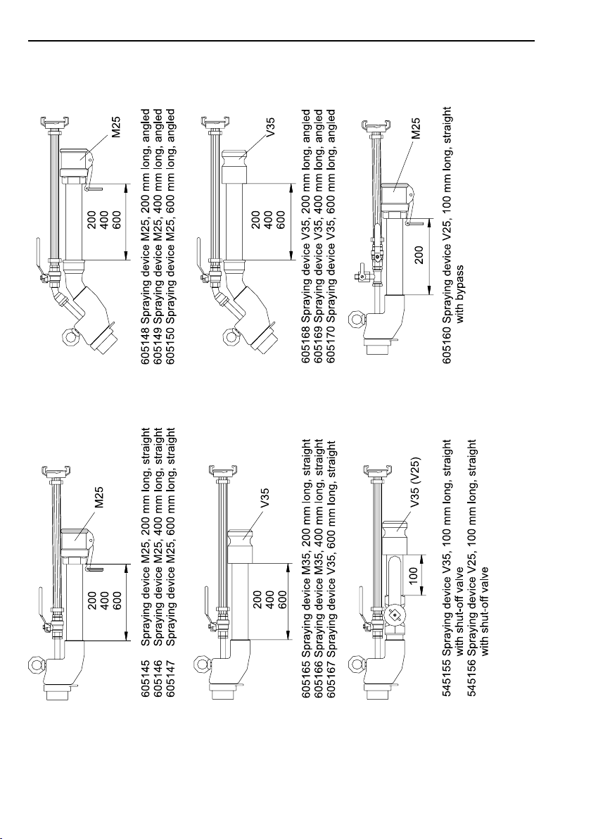
50 P50
Fig 14 – Overview of spray guns
392425 - 2011-09
Page 51

51
392425 - 2011-09
 Loading...