

Page 1
Page 2

This page intentionally left blank
Page 3

TABLE OF CONTENTS
1. SAFETY .................................................................................................................................................... 4
W
ARNINGS AND CAUTIONS .......................................................................................................... 4
ENERAL SAFETY INSTRUCTIONS ................................................................................................ 5
G
2. GENERAL INFORMATION ...................................................................................................................... 6
R
ECEIPT & REPAIR STATEMENT .................................................................................................. 6
W
ARRANTY ................................................................................................................................. 6
3. HOW TO INSTALL ................................................................................................................................... 7
I
NSTALLATION CHECKLIST ........................................................................................................... 7
P
OWER WIRING CONNECTION ..................................................................................................... 9
C
OMMON MODE ASSEMBLY CONNECTION ................................................................................. 10
M
ODULAR UNIT INTERCONNECTION DIAGRAM ............................................................................ 12
NCLOSED UNIT INTERCONNECTION DIAGRAM ........................................................................... 13
E
B
ASIC SCHEMATIC DIAGRAM ..................................................................................................... 14
T
RANSFORMER DIAGRAM .......................................................................................................... 15
C
OMMON MODE ASSEMBLY CONNECTION DIAGRAM .................................................................. 16
T
ORQUE RATINGS 380-480V .................................................................................................... 17
ORQUE RATINGS 600V ........................................................................................................... 18
T
4. START-UP .............................................................................................................................................. 19
S
AFETY PRECAUTIONS .............................................................................................................. 19
5. TROUBLESHOOTING ............................................................................................................................ 21
List of Figures
Figure 3-1: Modular Interconnection ........................................................................................... 12
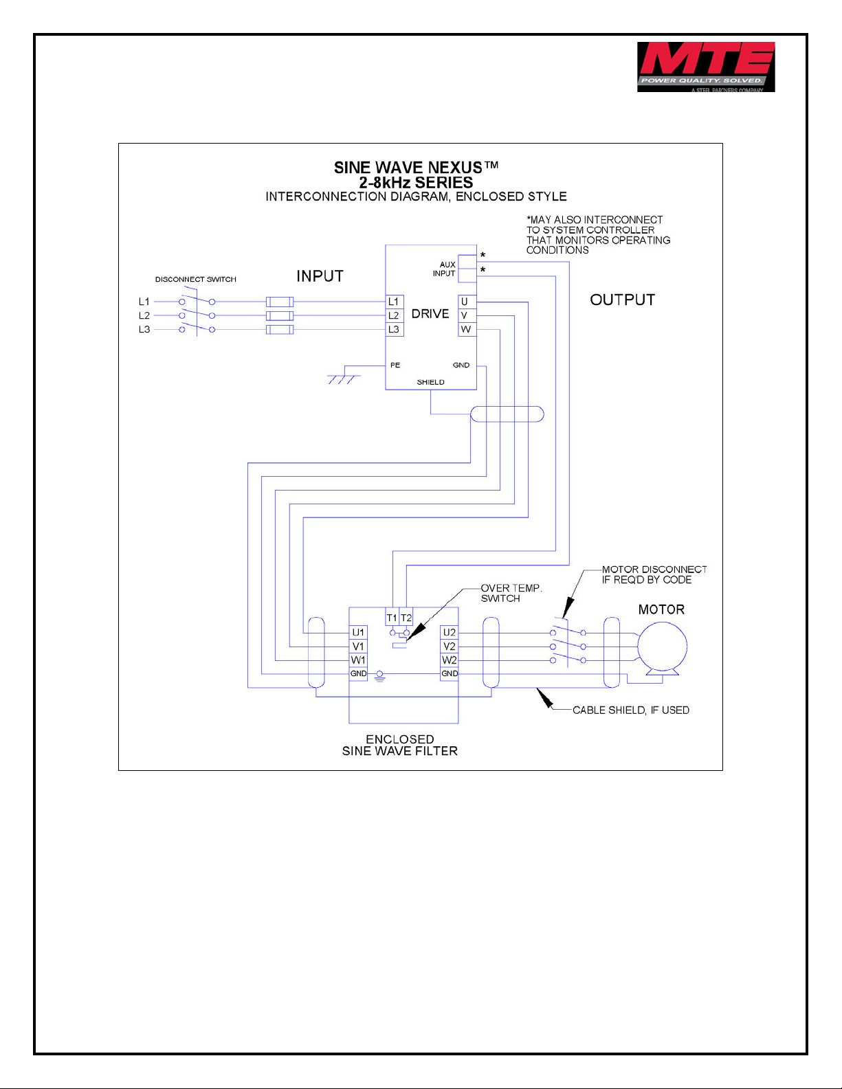
Figure 3-2: Enclosed Interconnection ......................................................................................... 13
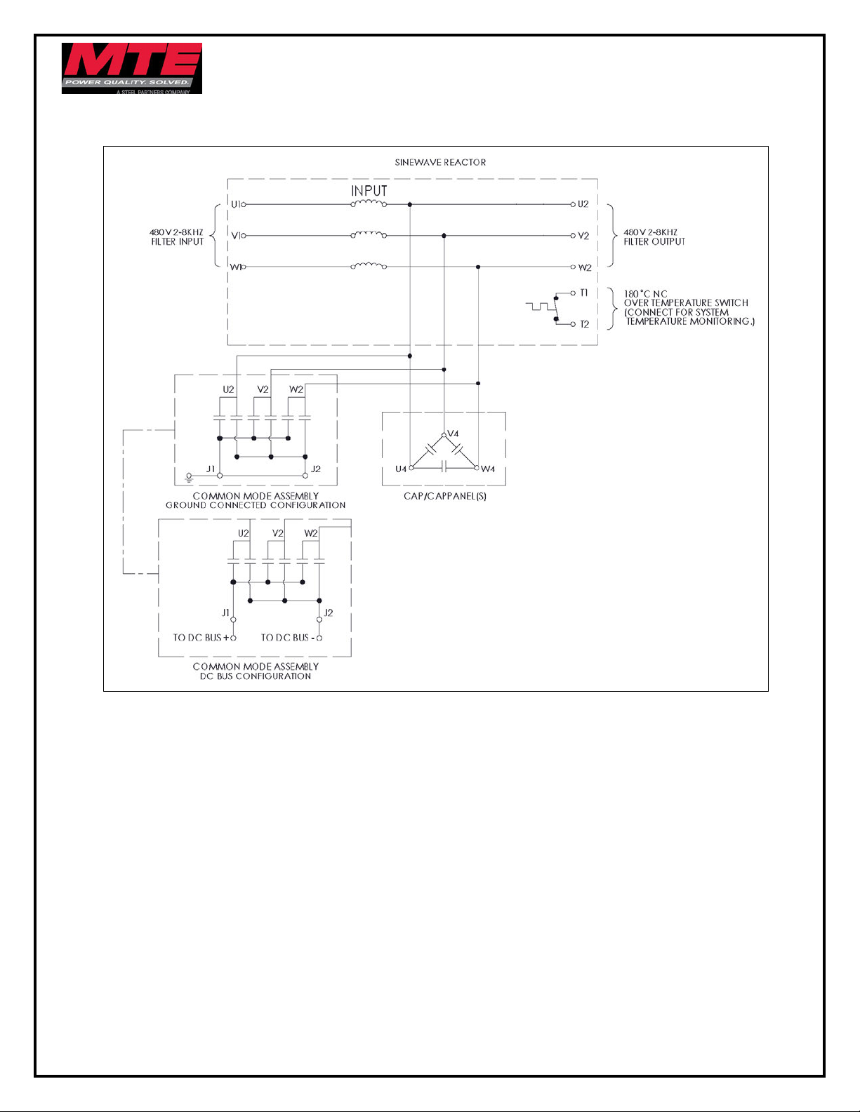
Figure 3-3: Basic Schematic Diagram ........................................................................................ 14
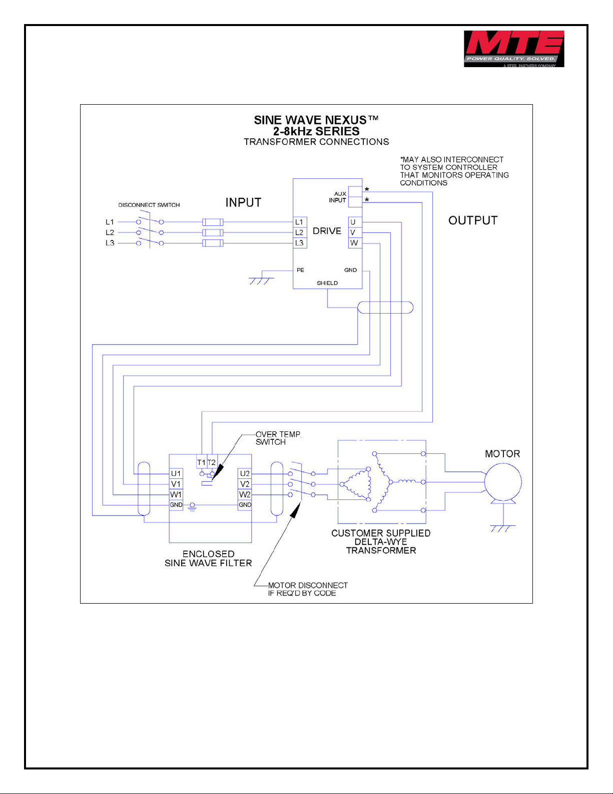
Figure 3-4: Transformer Diagram ............................................................................................... 15
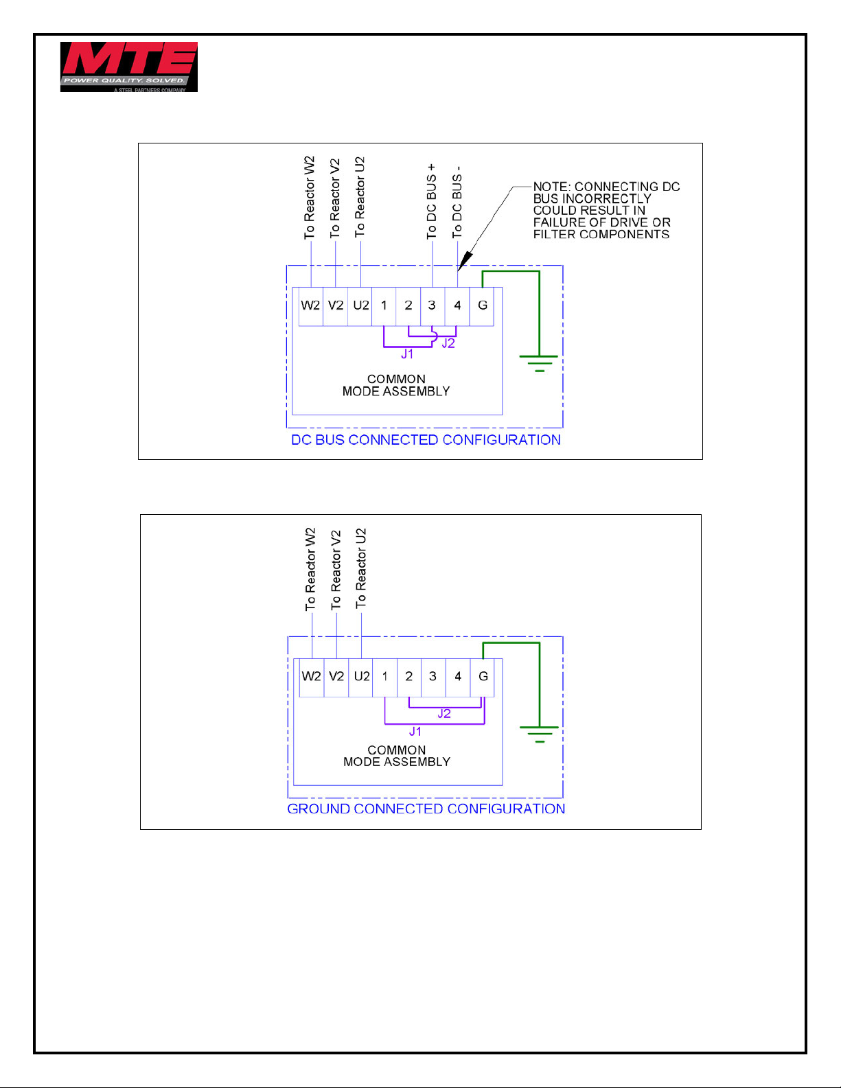
Figure 3-5: DC Bus Connected Configuration ............................................................................ 16
Figure 3-6: Ground Connected Configuration ............................................................................. 16
List of Tables
Table 3-1: Overtemperature Switch .............................................................................................. 8
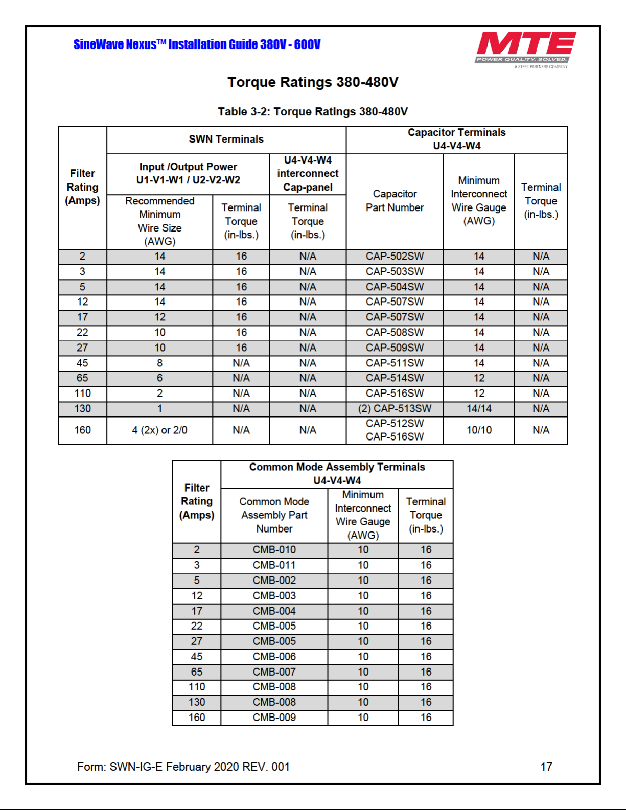
Table 3-2: Torque Ratings 380-480V .......................................................................................... 17
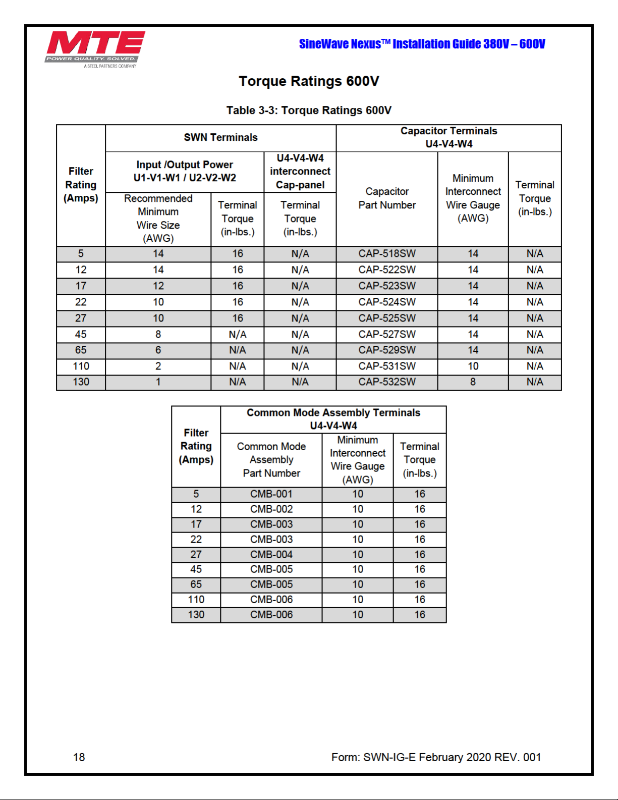
Table 3-3: Torque Ratings 600V ................................................................................................. 18
Table 5-1: Performance Specifications ....................................................................................... 22
Table 5-2: Troubleshooting Guide .............................................................................................. 23
Page 4
WARNING
WARNING
1. SAFETY
Warnings and Cautions
The following symbols are used in this manual:
High Voltage Warning: warns of situations that dangerously
Caution
high voltage is involved. Failure to use proper precautions may
lead to serious injury or death.
General Warning: warns of situations that can result in serious
injury or death if proper precautions are not used.
General Caution: identifies situations that could lead to
malfunction or possible equipment damage.
SineWave Nexus™ Installation Guide 380V – 600V
4 Form: SWN-IG-E February 2020 REV. 001
Page 5
SineWave Nexus™ Installation Guide 380V - 600V
High Voltage! Only a qualified electrician can carry out the electrical
installation of this filter.
High voltage is used in the operation of this filter. Use extreme caution to
observed.
General Safety Instructions
WARNING
WARNING
avoid contact with high voltage when operating, installing or repairing this
Injury or death may result if safety precautions are not
filter.
The opening of the branch circuit protective device may be an indication
that a fault current has been interrupted. To reduce the risk of fire or
electrical shock, current-carrying parts and other components of the filter
should be examined and replaced if damaged.
An upstream disconnect/protection device must be used as required by
the National Electrical Code (NEC) or governing authority.
Even if the upstream disconnect/protection device is open, the drive
downstream of the filter may feed back high voltage to the filter. The drive
safety instructions must be followed. Injury or death may result if safety
precautions are not observed.
The filter must be grounded with a grounding conductor connected to all
grounding terminals. Modular filters must have reactor grounded through
a 2”x2” area cleaned of paint and varnish on lower mounting bracket.
Only spare parts obtained from MTE Corporation or an authorized MTE
distributor can be used.
Caution
After removing power, allow at least five minutes to elapse and verify that
the capacitors have discharged to a safe level before contacting internal
components. Connect a DC voltmeter across the capacitor terminals and
ensure that the voltage is at a safe level.
Review the schematic prior to connecting unit in DC Bus Configuration.
Connecting the unit incorrectly could result in failure of drive and filter
components.
Loose or improperly secured connections may damage or degrade filter
performance. Visually inspect and secure all electrical connections before
power is applied to the filter.
Prior to start-up; confirm the drive operation mode is property set (Volts
per Hertz). Please consult drive manual/manufacturer to configure proper
parameters. Failure to do so may result in failure of drive or filter
components.
Form: SWN-IG-E February 2020 REV. 001 5
Page 6

SineWave Nexus™ Installation Guide 380V – 600V
2. GENERAL INFORMATION
The purpose of the manual is to aid in the proper installation of the SineWave Nexus.
For most current information, please refer to website:
http://www.mtecorp.com/nexus-sinewave-filter/
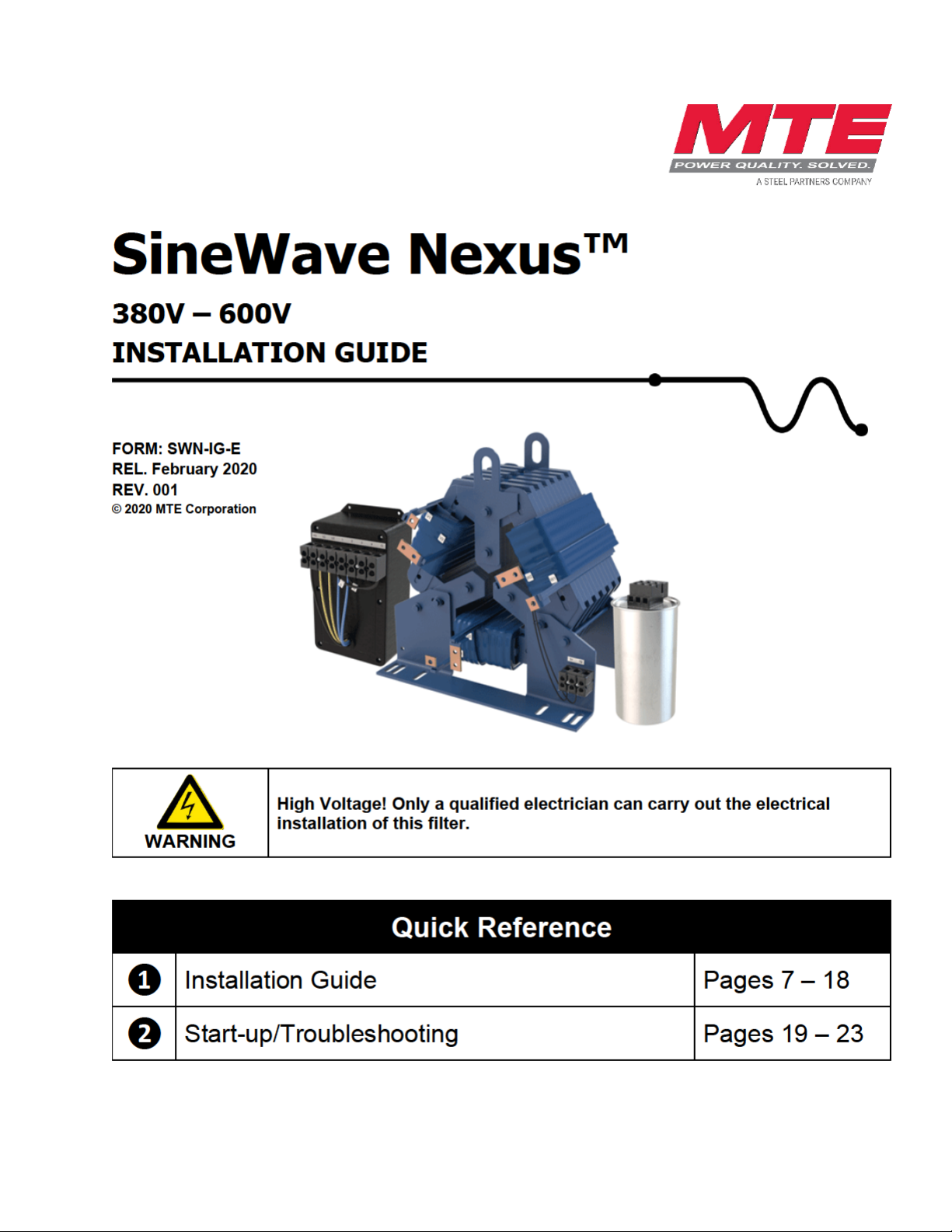
SineWave Nexus filters transform the output of Variable Frequency Drives (VFDs) to a near
perfect sinusoidal waveform for the best level of motor protection. MTE's unique design offers
high performance in both differential and common mode with smaller size and better efficiency
than traditional industry solutions.
Receipt & Repair Statement
Upon Receipt of this Filter:
The SineWave Nexus motor protection filter has been subjected to demanding factory tests
before shipment. Carefully inspect the shipping container for damage that may have occurred in
transit. Then unpack the filter and carefully inspect for any signs of damage. Save the shipping
container for future transport of the filter.
In the event of damage, please contact and file a claim with the freight carrier involved
immediately.
If the equipment is not going to be put into service upon receipt, cover and store the filter in a
clean, dry location. After storage, ensure that the equipment is dry and that no condensation or
dirt has accumulated on the internal components of the filter before applying power.
Warranty
Three years from the date of shipment. See http://www.mtecorp.com/industry-leading-warranty/
for details.
6 mtecorp.com Form: SWN-IG-E February 2020 REV. 001
Page 7
SineWave Nexus™ Installation Guide 380V - 600V
WARNING
3. HOW TO INSTALL
Installation Checklist
Prior to installation, please review the safety instructions on page 4 & 5.
Failure to practice this can result in body injury!
WARNING
SineWave Nexus filters are supplied in the following mechanical configurations:
• Modular: Modular units consist of a reactor, a common mode assembly and one or more
capacitor or capacitor panel assemblies (referred to as cap-panels on drawings and
diagrams). Additional wiring between the reactor, common mode assembly and
capacitor/capacitor panel assembly is required by customer.
• Floor mounted general purpose NEMA 1/2 and NEMA 3R cabinets: Reactor, common mode
assembly and capacitor/capacitor panel assemblies are supplied in a cabinet with all items
pre-wired together.
Minimum Required Space:
Open panel SineWave Nexus filters are designed for mounting within the customer’s enclosure.
When determining the internal temperature rise and cooling requirements of the enclosure,
include the power dissipation of the filter along with all the other components located in the panel.
A general guideline is to allow a side clearance of four (4) inches and a vertical clearance of six
(6) inches for proper heat dissipation and access within the enclosure. Clearances may be less if
proper ventilation exists. Filter components must operate within temperatures specified in this
manual or filter operating life will be compromised. Also, be aware of minimum electrical
clearances as defined by the appropriate system safety standard(s). Modular SineWave Nexus
filters generate heat and should be positioned away from heat sensitive components. Avoid
locations where the filter would be subjected to excessive vibrations. Locate the filter as close to
the inverter as possible.
NOTE: Locate the capacitor(s) and common mode assembly in the lowest temperature
regions of the enclosure – generally toward the bottom and away from high temperature
components.
General purpose NEMA 1/2 and NEMA 3R enclosed filters are designed for floor mounting in an
environment suitable for the enclosure type. Do not install in or near a corrosive environment.
Avoid locations where the filter would be subjected to excessive vibrations. Allow a minimum side
and back clearance of eight (8) inches and front clearance of thirty-six (36) inches for proper heat
dissipation and access.
Input and output wiring to the filter should be performed by authorized
personnel in accordance with NEC and all local electrical codes and
regulations.
The filter is designed for use with copper conductors with a minimum
temperature rating of 75 degrees C.
Form: SWN-IG-E February 2020 REV. 001 7
Page 8
SineWave Nexus™ Installation Guide 380V – 600V
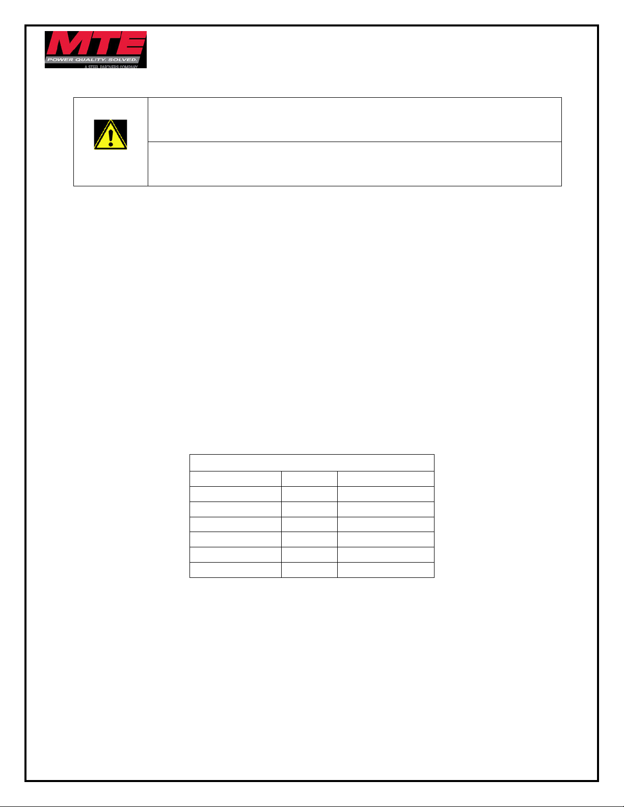
NC Switch opens at 180 Deg. +/- 5 Deg. C
Current Amps
Voltage
Contact Load
6
120 AC
Resistive Loads
3
120 AC
Inductive Loads
3
240 AC
Resistive Loads
2.5
240 AC
Inductive Loads
8
12 VDC
Resistive Loads
4
24 VDC
Resistive Loads
Grounding
The filter must always be grounded with a grounding conductor connected to ground
terminals.
WARNING
NOTE: For cable shield grounding follow the drive manufacturer’s recommendations.
Grounding and Ground Fault Protection
Due to high leakage currents associated with variable frequency drives, ground fault protective
devices do not necessarily operate correctly. When using this type of device, its function should
be tested in the actual installation.
Overtemperature Interlock
An overtemperature interlock circuit should be used in conjunction with thermal switch to turn off
the drive to prevent filter damage due to abnormal operating conditions. The temperature switch
is normally closed and will open when an internal reactor temperature of 180°C is reached. See
Table 3-1: Overtemperature Switch, below for contact rating information and the drive user
manual for interconnection information.
For modular units, ensure a 2” X 2” area is cleaned of paint and varnish on lower
mounting bracket for ground connection.
Table 3-1: Overtemperature Switch
MTE highly recommends the use of the overtemperature switch to prevent damage to the filter
in rare instances of overheating from abnormal operating conditions.
8 Form: SWN-IG-E February 2020 REV. 001
Page 9
SineWave Nexus™ Installation Guide 380V - 600V
Power Wiring Connection
Input and output power wiring to the filter should be performed by authorized
personnel in accordance with the NEC and all local electrical codes and
regulations.
Cable lugs and mounting hardware are provided by the customer.
WARNING
Verify that the power source to which the filter is to be connected is in agreement with the
nameplate data on the filter. A fused disconnect switch or circuit breaker should be installed
between the drive and its source of power in accordance with the requirements of the NEC and
all local electrical codes and regulations. Refer to the drive user manual for selection of the
correct fuse rating and class.
The typical interconnection diagrams that follow are shown for a motor load, but the load can be
either a motor or a transformer.
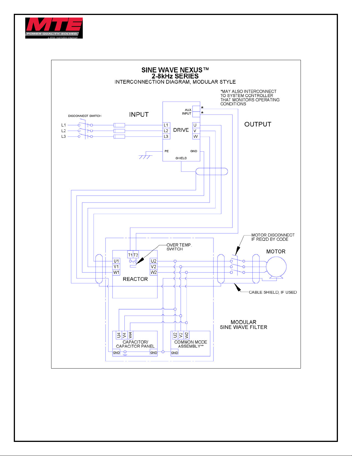
• For modular filter applications, interconnection between the filter, its power source, the
capacitor(s), the common mode assembly and the drive is shown in Figure 3-1: Modular
Interconnection (p12).
• For filters supplied in general purpose NEMA 1/2 & NEMA 3R cabinets, interconnection
between the filter, its power source, the motor, and the drive is shown in Figure 3-2:
Enclosed Interconnection (p13).
• For transformers, interconnection between the power source, the filter, the motor and the
drive is shown in Figure 3-4: Transformer Diagram (p15).
Wire gauge range and terminal torque requirements as well as selecting conductors that
interconnect the reactor, capacitor(s) and common mode assembly are shown in Table 3-2:
Torque Ratings 380-480V (p17) and Table 3-3: Torque Ratings 600V (p18).
Refer to the drive user manual for instructions on interconnecting the drive and motor and the
correct start-up procedures for the drive.
The filter is designed for use with copper conductors with a minimum temperature rating of 75
degrees C.
Any extremely low or high resistance readings indicate miswiring and may
result in damage to filter components if not corrected.
On NEMA 3R enclosures, CAB-26AP and larger, no live parts shall be mounted
below 8 inches from the bottom of the enclosure.
Form: SWN-IG-E February 2020 REV. 001 9
Page 10
SineWave Nexus™ Installation Guide 380V – 600V
Review the schematic prior to connecting unit in DC Bus Configuration.
When attempting to connect the filter to the DC Bus of the drive, p
lease consult
Common Mode Assembly Connection
Connecting the unit incorrectly could result in failure of drive and filter
components
WARNING
The type of power distribution transformer that is used in the system feeding the drive will
determine the recommended method for connecting the common mode assembly. The common
mode assembly can be connected in two different ways dependent upon the type of system it is
used in.
NOTE: The recommended connection configuration for optimal performance is the DC
Bus Connected Configuration.
Solidly Grounded or High Resistance Grounded WYE Systems
With a solidly grounded wye or high resistance grounded wye transformer secondary, we
recommend using the ground connected configuration, shown in Figure 3-6: Ground Connected
Configuration (p16). The common mode assembly is connected in this configuration by default.
drive manual/manufacturer for proper connection points. Failure to do so may
result in failure of drive or filter components.
Floating WYE or Delta System
With a floating wye transformer secondary or with a delta transformer secondary, we recommend
using the DC Bus connected configuration, shown in Figure 3-5: DC Bus Connected
Configuration (p16).
Note: Exotic delta transformer secondary schemes like corner grounded delta and high-leg delta
are also included in this category.
Systems in Which the Transformer or Grounding Details Are Unknown
If this information is not available, we recommend using the DC Bus Connected Configuration,
shown in Figure 3-5: DC Bus Connected Configuration (p16).
Converting from Ground Connected Configuration to DC Bus Connected Configuration
Changing the common mode assembly from the grounded config to the DC Bus connected
config can be done in two easy steps.
1. Move jumpers J1 and J2 from the ground connection terminal G to bottom side of
terminals 3 and 4 respectively
2. Wire the top side of terminals 3 and 4 to the DC Bus in the drive.
Note: Recommended wire size for this connection is 12-14 AWG
10 Form: SWN-IG-E February 2020 REV. 001
Page 11

SineWave Nexus™ Installation Guide 380V - 600V
Wiring Checks
Using Figure 3-3: Basic Schematic Diagram (p14), visually check the wired components to
confirm, verify, and correct wiring. Then, with a multimeter, check phase to phase isolation using
the 100 K ohm range. The multimeter will read the parallel equivalent of the bleeder resistors
after the capacitors initially charge. All phase to phase resistance values should be the same.
Check for the Following Faults:
• Capacitor shorted
• Capacitor bus not connected
• Capacitor bus to chassis short
• Parallel wiring errors
Torque Ratings Tables
Please see Table 3-2: Torque Ratings 380-480V (p17) and Table 3-3: Torque Ratings 600V
(p18) for torque ratings.
NOTE: Cap-panel interconnect wiring specification according to UL508 75° C Table.
NOTE: To prevent flexing or bending of the coil windings attached to SWN reactor use
appropriate strain relief to prevent stress on terminals. For flat copper terminal tabs, use
two wrenches to tighten customer provided cable mounting hardware.
NOTE: Refer to reference drawings for termination wire ranges.
Form: SWN-IG-E February 2020 REV. 001 11
Page 12
SineWave Nexus™ Installation Guide 380V – 600V
Modular Unit Interconnection Diagram
Figure 3-1: Modular Interconnection
**See Figure 3-5 (p16) and Figure 3-6 (p16
12 Form: SWN-IG-E February 2020 REV. 001
) for Common Mode Assembly connection diagrams
Page 13
SineWave Nexus™ Installation Guide 380V - 600V
Enclosed Unit Interconnection Diagram
Figure 3-2: Enclosed Interconnection
See Figure 3-5 (p16) and Figure 3-6 (p16
Form: SWN-IG-E February 2020 REV. 001 13
) for Common Mode Assembly connection diagrams
Page 14
Basic Schematic Diagram
SineWave Nexus™ Installation Guide 380V – 600V
Figure 3-3: Basic Schematic Diagram
See Figure 3-5 (p16) and Figure 3-6 (p16
14 Form: SWN-IG-E February 2020 REV. 001
) for Common Mode Assembly connection diagrams
Page 15
SineWave Nexus™ Installation Guide 380V - 600V
Transformer Diagram
Figure 3-4: Transformer Diagram
See Figure 3-5 (p16) and Figure 3-6 (p16) for Common Mode Assembly connection diagrams
Form: SWN-IG-E February 2020 REV. 001 15
Page 16
SineWave Nexus™ Installation Guide 380V – 600V
Common Mode Assembly Connection Diagram
Figure 3-5: DC Bus Connected Configuration
Figure 3-6: Ground Connected Configuration
Note: Refer to the Common Mode Assembly Connection section (p10) for details on
converting from the Ground Connected Configuration to the DC Bus Configuration
16 Form: SWN-IG-E February 2020 REV. 001
Page 17
Page 18
Page 19
SineWave Nexus™ Installation Guide 380V - 600V
4. START-UP
Safety Precautions
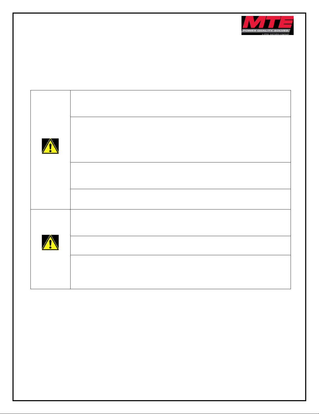
Before start-up, observe the following warnings and instructions:
Internal components of the filter are at line potential when the filter is connected to
the drive. This voltage is extremely dangerous and may cause death or severe injury if
you come in contact with it.
Remove all power to the SineWave filter in compliance to standardized 26 CFR
1920.147 lockout/tagout policies.
WARNING
After disconnecting the utility power, allow at least 5 minutes to elapse and verify
that the capacitors have discharged to a safe level before contacting internal
components.
the voltage is at a safe level.
Use extreme caution to avoid contact with line voltage when checking for power.
INJURY OR DEATH MAY RESULT IF SAFETY PRECAUTIONS ARE NOT
OBSERVED.
Connect a DC voltmeter across the capacitor terminals and ensure that
Review the schematic prior to connecting unit in DC Bus Configuration. Connecting
the unit incorrectly could result in failure of drive and filter components.
Prior to start-up; confirm the drive operation mode is properly set (Volts per Hertz).
Please consult drive manual/manufacturer to configure proper parameters. Failure to
do so may result in failure of drive or filter components.
Damage to the filter may occur if the switching frequency is not set between 2
kHz and 8 kHz. Optimum switching frequency is at 4kHz and above.
Caution
MTE recommends 10 seconds as an initial starting point for motor ramp time and
that customers examine the actual inrush and ratings of their drive system. Inrush
current seen at the drive from the filter that can easily be overcome by changing the
motor ramp time.
Form: SWN-IG-E February 2020 REV. 001 19
Page 20

SineWave Nexus™ Installation Guide 380V – 600V
Sequence of Operation
1. Read and follow safety precautions.
2. After installation, ensure that:
a. All filter ground terminals are connected to ground.
b. Power wiring to the utility, drive, filter and motor is in accordance with the power
wiring connection diagrams shown in installation instructions section.
3. Check that moisture has not condensed on the filter components. If moisture is present,
do not proceed with start-up until the moisture has been removed.
4. Disconnect filter output terminals from the motor.
5. Set the drive switching frequency between 2 kHz and 8 kHz. Refer to the drive user
manual.
6. Connect filter temperature safety overload switch into the control circuit so that the drive
will shut down in an overload situation.
7. Confirm that drive voltage is present at the input terminals (U1, V1, W1) of the filter.
8. Confirm that drive voltage is present at the output terminals (U2, V2, W2) of the filter.
9. Connect the filter output to the motor.
10. Refer to the drive user manual for the drive start-up procedure. Observe all safety
instructions in the drive user manual.
20 Form: SWN-IG-E February 2020 REV. 001
Page 21
SineWave Nexus™ Installation Guide 380V - 600V
When properly installed, this equipment has been designed to provide maximum
High voltage is used in the operation of this filter. Use Extreme caution to avoid
IF SAFETY PRECAUTIONS ARE NOT
After removing power, allow at least five minutes to elapse and verify that the
5. TROUBLESHOOTING
safety for operating personnel.
However, hazardous voltages and elevated temperatures exist within the confines
of the enclosure. Servicing should therefore be performed by qualified
personnel only and in accordance with OSHA Regulations.
WARNING
contact with high voltage when operating, installing or repairing this filter.
OR DEATH MAY RESULT
OBSERVED
capacitors have discharged to a safe level before contacting internal components.
Caution
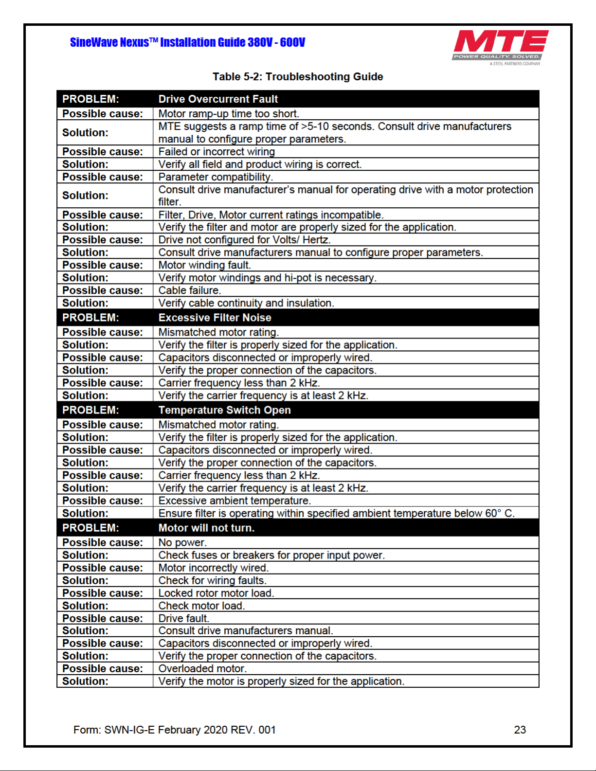
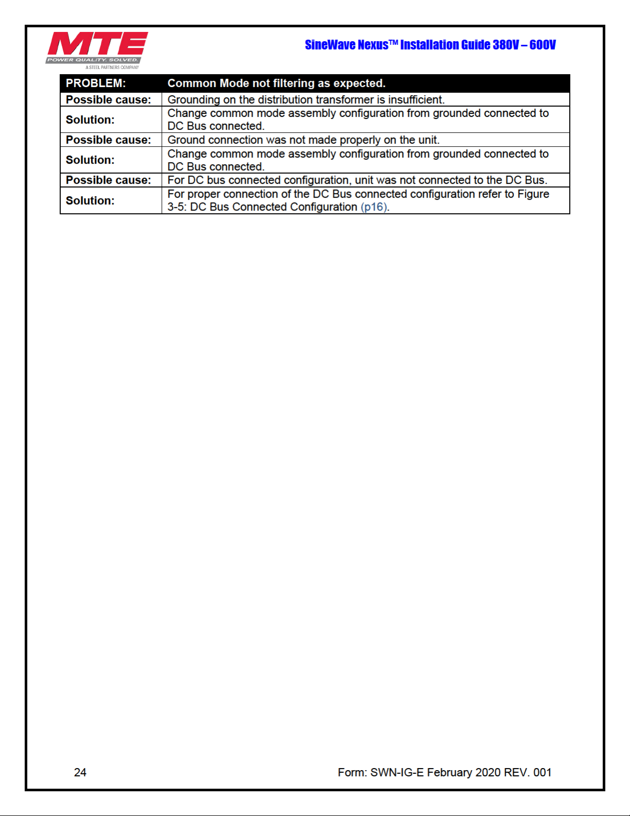
To aid in troubleshooting, a basic schematic diagram, interconnection diagrams, common mode
assembly connection diagrams and a troubleshooting guide that lists potential problems and
solutions are included:
Connect a DC voltmeter across the capacitor terminals or terminals U1, V1 or V1,
W1 and ensure that the voltage is at a safe level.
.
INJURY
Figure 3-1: Modular Interconnection (p12)
Figure 3-2: Enclosed Interconnection (p13)
Figure 3-3: Basic Schematic Diagram (p14)
Figure 3-4: Transformer Diagram (p15)
Figure 3-5: DC Bus Connected Configuration (p16)
Figure 3-6: Ground Connected Configuration (p16)
Table 5-2: Troubleshooting Guide (p23)
Form: SWN-IG-E February 2020 REV. 001 21
Page 22
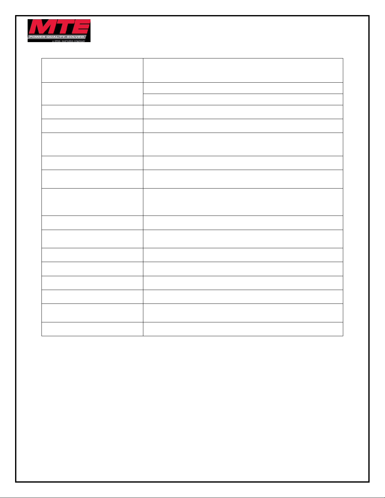
Conventional 3 phase motors operating in volts per Hertz
Standard step-up or delta-wye transformer
Table 5-1: Performance Specifications
SineWave Nexus™ Installation Guide 380V – 600V
Service Load Condition
Voltage
Input Voltage Wave Form PWM
Harmonic Voltage Distortion 5% maximum @ 4kHz
Common Mode Attenuation
Inverter Switching Frequency 2kHz – 8kHz (Optimal performance achieved @ 4kHz)
Inverter Operating Frequency
Maximum Ambient
Temperature
Insulation System Class N (200° C)
Insertion Loss (Voltage) 10% maximum @ 60Hz
mode
380-480V +/- 10%
600V +/- 10%
-20dB (>90% PWM common mode RMS voltage reduction) @
4-8kHz
6Hz to 75Hz,
>75Hz to 120Hz with derating
-40C to +60C Modular Filter
-40C to +55C Enclosed Filter
-40C to +90C Storage
Efficiency >98%
Altitude without derating 3,300 feet above sea level
Maximum Motor Lead Length 15,000 feet
Relative Humidity 0% to 95% non-condensing
Current Rating
Audible Noise 75dBA at 1 meter
NOTE: Filter does not mitigate any DC bus ripple that may be present, or 3rd order
harmonics injected by the drive.
100% RMS Continuous
150% for 1 minute Intermittent
22 Form: SWN-IG-E February 2020 REV. 001
Page 23
Page 24
 Loading...