

Page 1
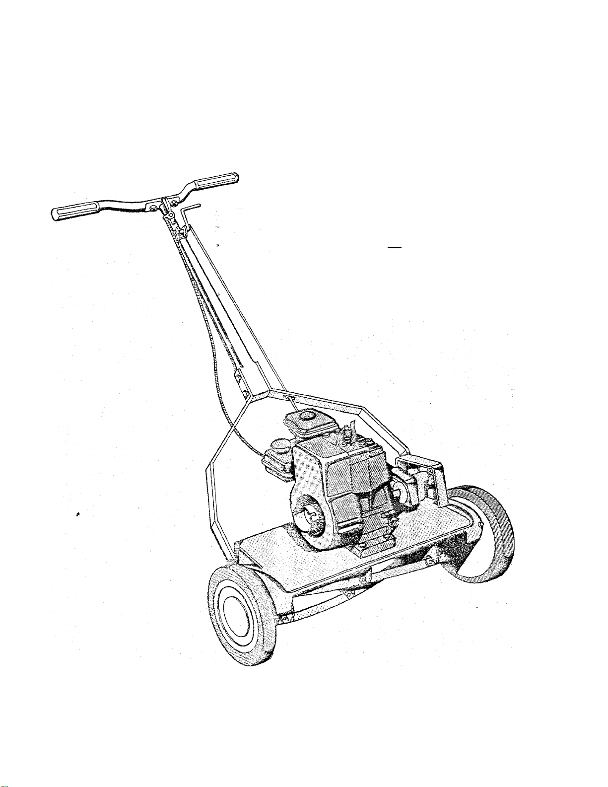
owner’s guide and parts list
MODEL NO. ZYJ-192A
MASTER COPY
00 NOT
REIL LAWN MOW®
^ S'
MONTGOMERY ¥MRD
Oôn-345
Page 2
BEFORE STARTING ENGINE
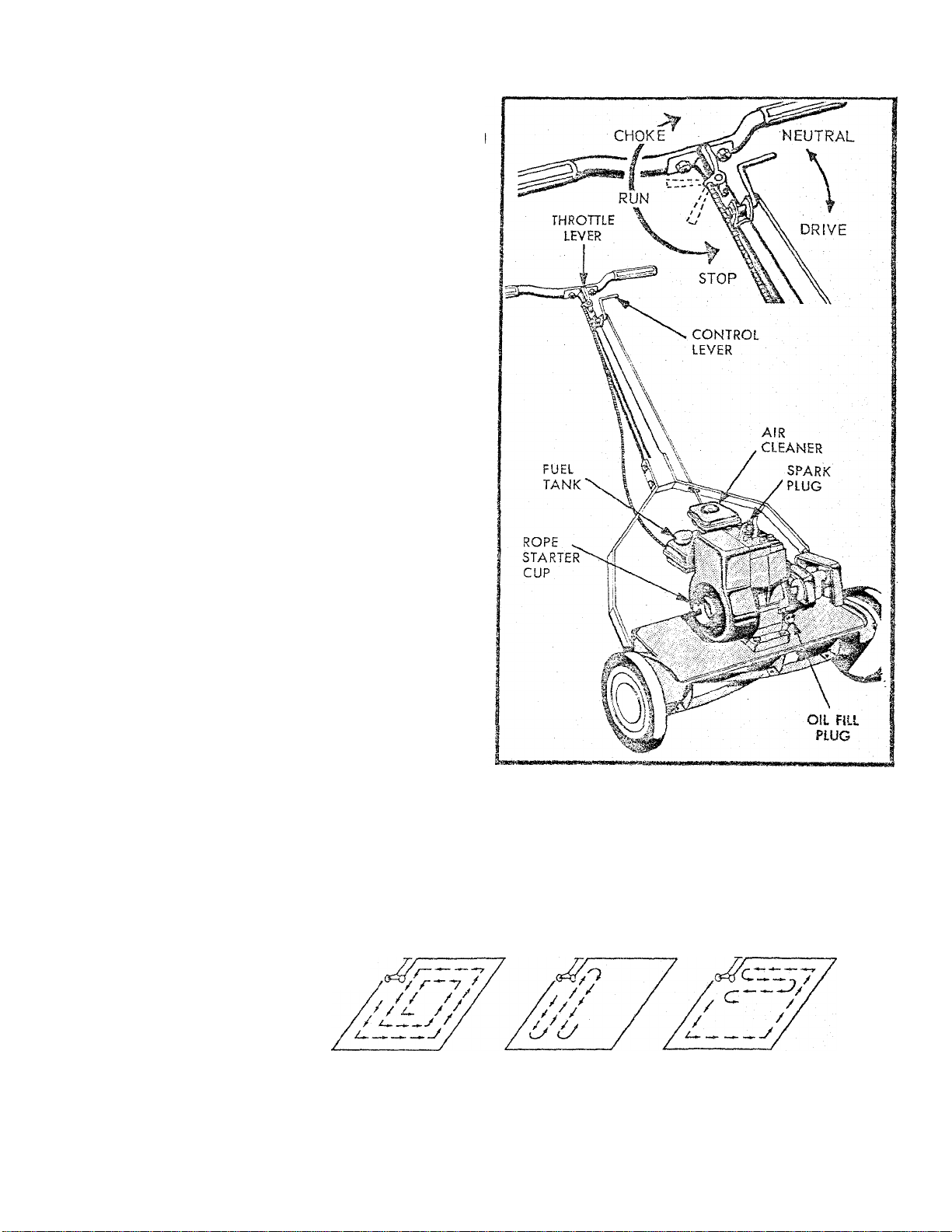
]. (Fig. 1) Remove oil fill plug. Place mower leve
and fill engine crankcase to top of oil fill plug
with S.A.E. No. 30 oil. Tilt mower to make sure
oil flows completely into crankcase. Replace fill
plug and tighten.
2. The air cleaner protects the engine agoinst grit
and dirt. CAUTION, an extremely dirty air cleaner
element may cause engine to stall. SEE ENGINE
INSTRUCTION MANUAL FOR PROPER AIR CLEANER
MAINTENANCE.
3. Fill tank with good grade regular, clean fresh
gasoline. DO NOT MIX OIL with gasoline.
FOR COMPLETE ENGINE INFORMATION READ ENGINE
INSTRUCTION BOOKLET FURNISHED WITH YOUR
MOWER BEFORE STARTING OR OPERATING-
TO START ENGINE
1. Move control lever to NEUTRAL position
2. Set throttle lever in choke position.
3. Pull starter rope with quick full stroke once. Move
throttle lever to "FAST" position. Pull starter rope
again.
4. When engine starts move throttle lever to "IDLE"
position until engine warms up- Regulate engine
speed with hand lever from "IDLE" to "FAST."
OPERATING CONTROLS
1. Set operating control lever to "DRIVE" position
for rnovving
2. Throttle lever regulates choke, run, idle and stop.
OPERATING AND LAWN MOWING HINTS
1. Don't cut your grass to short. The best height is 1 l-i
to 2 inches. See instructions for cutting height ad
justment.
USE A SYSTEM
WHEN YOU MOW
3*3ts ths edges
fosf and it's
2. Your Power Reel mower is easy to transport. Push
down on handle, tilt mower on rollers and push
your mower. The blades will be raised for passing
over rocks, curbs, etc.
A pause at eoch end is
more restfu! but it misses
the edges.
COMBINE FOR
BEST RESULTS
Page 3
IMPORTANT
DISCONNECT SPARK PLUG WIRE BEFORE MAKING MOWER ADJUSTMENTS.
ADJUSTMENTS
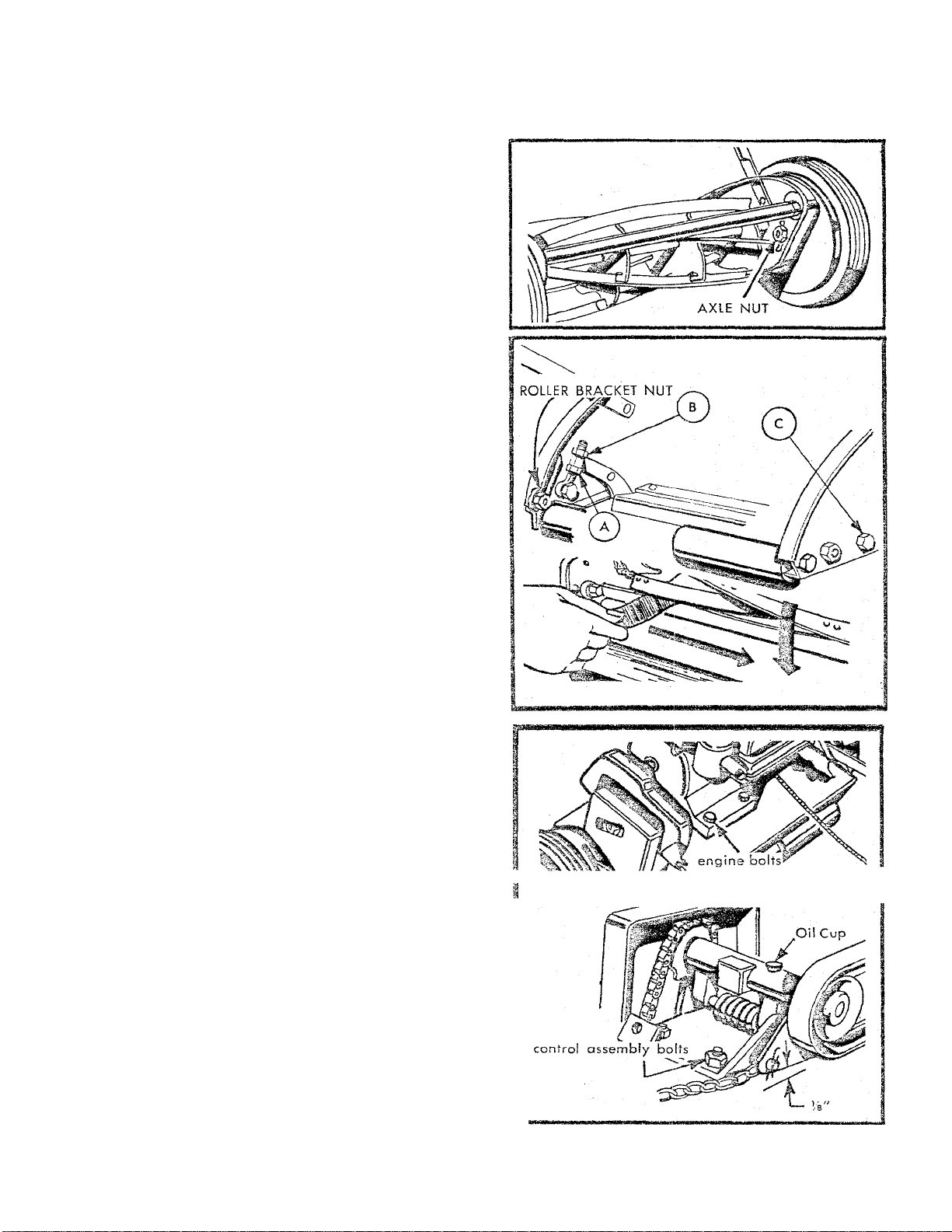
TO CHANGE WHEELS FROM
HIGH TO LOW CUT
1. Loosen axle nuts on inside of end plates and move
axle up to desired position (Fig. 2). Be sure both
wheels are located in same relative position and
tighten axle nuts securely. IMPORTANT axle nut
shoulders must be properly seated in notches.
TO ADJUST ROLLER
Loosen roller bracket nuts and move roller up or down
to attain desired height of cut and level chassis.
TO TIGHTEN CUTTER BAR
ADJUSTMENT
1. Loosen lower adjusting nut (A) and tighten upper
adjusting nut (B) until reel contacts cutter bar
lightly (Fig. 3). Adjustment may also be determined
by inserting strip of newspaper between reel and
cutting bar. Reel should cut the paper when turned
backwards slowly. Tighten nuts (A) and (B) securely.
2. IMPORTANT Cutter bar pivot bolts (C) must be
tight offer adjustment. Right hand pivot bolt on
right hand side of mower must be turned counter ■
clockwise, left hand pivot bolt must be turned
clockwise to tighten.
TO ADJUST CHAIN DRIVE
1. Set hand control lever in "DRIVE" position.
2. Loosen 4 engine mount bolts and puli engine back.
3. Loosen 4 control assembly bolts,
4. Pull the control assembly back to tighten chain.
Allow Is inch slack in chain. Tighten 4 control
bolts. Leave spacer plate nut loose.
TO TIGHTEN DRIVE BELT
1. Loosen engine mounting bolts, place control lever
in drive position, and move engine forward
until approximately Vs" clearance Is attained be
tween belt guard bracket and mower deck as
shov/n, RetIghten engine bolts securely.
LyBRICATiON
1. Seals on all bearings hold dirt out and grease in.
Your mower left the factory properly lubricated at
these points and no further offenfion is required
until mower is sharpened.
2. Lubricc te roller and Jackshaft periodically os reqcl.
belt guard bracket
Page 4

Page 5

WARRANTY
This lawn mower was inspected before shipment from our factory. We warrant
it to be free from defects in material and workmanship and to operate satis
factorily when used for the purpose designed, provided it is properly assembled
and operated according to the Owner's Guide.
WARRANTY—For a period of one year from date of purchase. Wards will furnish
without charge, when brought to a Ward Branch, any labor necessary to repair,
replace or examine any part or assembly of this mower that is defective in
materia! or workmanship subject to our examination.
This Warranty is in lieu of ail other warranties, expressed or implied.
PARTS LIST
MODEL - ZYJ ~ 192A
r left hand (L.H.) as
PART NO.
REF.
LTR.
2132-42-48
A
3603-53-41
B
1538-8
C
1529-15
D
E 70
769
F
2117-21-41
G
H 67
1509-31
1
2664-5-41
J
1710-7
K
1 112-22-48
L
1530-19
M
1 129-193L-4
N
313529-48
O
1129-194R--
P
1652-51
Q
1540-22
R
1650-24
S
323
T
1635-29
u
V 1531-11
2604-24
W
3134-19-48
X
Y 451
52
z
1635-30
AA
BB 1658-15
1540-59
cc
1624-73
DD
2632-90
EE
2609-194-41
FF
877
GG
1118-17-48
HH
3636-15
il
NAME OF PART
Engine Bracket
Handle Brace.
Nut (M-20 Lock)
*Bolt (34-20 X %. Carr.)
*Nut (3<6-18 hex)---------
*Bo!t (Fi's-IS X 2 hex hd)
Handle Shaft....
*Nut (34-20 hex)
-----------------------
------
-------------------
_____________
-------------
-----
-------
----------
.................
.........
_____________
*Boit (34-20 X hex. hd.).....
Cross Handle
Handle Grip
Spacer Tube
* Rivet
_______________________
__________-
________ ___
_________
....
_____
_______
48 End Plate—L.H-------------------------
Reel Assy
48 End Plate—R.H
Bearing
Washer
__________________
______________
------
-----------------------------
_____________________
Retaining Ring______________
Pawl
____
____------
Pinion—R.H
*Rivet________________
Blade
____________
Cutter Bar with blade
Bolt
________________________
------------
------
_____________—
___
___
_______
------------
_
*Nut (/i-24 hex)_______________
Pinion—L.H
Roller.....:
*Washer
Spacer
Roller Shaft
8 Bracket—L.H
-------------
-------- ------
__________
----
----------------
__________
_________________
________
____
__________ ______
-----------
____
___
*Nut %-24 Hex. Lock "Gripco"
Gear Housing
Wheel
__________
____________
________
___
REF. PART NO.
LTR.
1137-3
JJ
1513-42
KK
1631-27
LL
1540-31
MM
1650-22
NN
2619-31
CO
2674-23-41
pp
1507-3
QQ
116
.
RR
SS
TT
UU
117
1552-7
109
W 455
1694-12
WW
XX
1511-12
1509-86
YY
1509-37
BA
BC 1539-33
BD 2609-195-48
2121-12
BE
BF 1548-5
1609-199
BG
1545-7
BH
1654-9
B1
BJ 1683-16
1509-2
BK
153S-8
8L
1132-26
BM
1547-4
BN
1509-3
BO
2142-48
BP
1534-8
BQ
NAME OF PART
Nut—Special
Screw—Special..
Axle
_______
Washer
^Retaining Ring
Tire...____
Hub Cap
‘Screw (10-32)
*Nuf (10-32 square)
‘Screw (10-32 x 34)
Wave Washer
Felt Wosher
Screw—Special
Clamp
________________
______
___
______
_______
_____________________
_______
____
___
___
___ ____
_____
_____
______
_______
________
___________
___________
_____
__________
__________
__________
_____
______
___
_______
Screw (10-32 X % Thd. Cut.'
Screw (/s-24—L.H. thd.)...
Bolt (3(6-18 X A)
Nut (3(6-18 Special)
Bracket—R.H
Sprocket
Roilpin____
____________
_________
________
_____
___________________
___
______________
Bracket________________
Clevis Pin
Chain
Clutch Red
Bolt (34-20 X VA)
Nut (34-20 Lock)
Lever & Brkt Assy
Hairpin Cotter
Bolt (10-32 X 134)
Throttle Control
Nut (10-32 Hex Lock).
___________
_____
___________________
___________
________
____________
__________
......
......
..............
___________
____________
_______
______
___
___
___
___
___
.......
___
____
_
_
_
_
.
_
For illustration See Page 4
'^Standard Hardware Item—May Be Purchosed Locally
Page 6

Page 7

J
HOW TO OBTAIN REPLACEMENT PARTS
Repair parts may be obtained from your Wards Retail
Store, Catalog Store, or Mail Order House and will be made
available at current prices, if requested, prices will be
quoted in advance. NOTE: Many of the nuts, bolts, etc.,
listed in the parts list of this m.anual ore standard hard
ware parts and are indicated with on asterickf*). These
parts may be purchased locally for your convenience and
for faster service. Check the Hardware Department of your
local store.
When requesting repair parts, be sure to give the model and serial number
which is shown on the model plate. Also give the part number and the name
of the part as shown in the repair parts listing. In addition, when ordering parts
for your gasoline engine, also furnish the information which appears on the
engine model plate. If you order by mail, you will pay the transportation
charges from the shipping point.
PARTS LIST
MODEL - ZYJ - 192A
PART NO.
REF.
NO.
ABriqqs & Stratton Engine Mode! 60101 Type 940239 Y
В 70
1025
C
1529-1 1
D
E
1724-7
1509-69
F
1651-20
G
1508-13
H
1
1548-1 1
J
2120-34-41
К
1540-17
L
1511-9
M
1540-55
N
1151-2-41
О
2102-20-48
P
3601-64-48
Q
1652-1
R
1691-2
S
1632-26
T
1546-2
u
1Ó54-2
V
1638-16
W
1036
X
NAAiE OF PART
*Nut {Xe Hex)----------------------------------------*Locl<washer (Xd)
*Bo!f (hd-IS X iVs Carriage)
Keeper-Belt Upper---------
*Screw (¡4-20 X 1% Fillister Hd.) —
"V" Belt...
Set Screw (/fs-24 x % Self Lock)
Rolipin
_____
Pulley Assembly.....................—-----------
*Washar {Vs x ’hid)....
*Screw (10-32 X 'A Sems. Ph.
Hd. Thd.) (Cutting)....
Washer
V/asher
____________________________
Beit Guard... ... ----------
Jackshaft Housing, Bearings &
Oiler Assembly....
Jackshaft Housing
Bearing
Oiler
Jackshaft..
Pin.......___
Chain
Sorocket.
___________________________
.....- --------------
.............
---------------
--------------------------------
------------------
---------------------
____
___________________
________
------
----------
_______________________
...........................
_____
—I-- -
------------
----
----
-------------
..............
------
-------------
-----------
------------------
-----
________________
-------------------
--------------
-------------------------
------------
------------
............
-------------
......
.. JJ
...........
---
---------
...
___
REF. PART NO.
NO.
Z
AA
BB
CC
DD 1642-30-48
EE
FF 1018
.
GG
HH
II
KK
LL 1605-256
MM
NN 1529-15
GO
PP
QQ
RR
SS
TT
Name of p.art
1538-16
1113-13
1650-10
1547-3
1534-8
67
3609-82-48
3639-42-48 Guard________________________•_...
1513-8
1501-20
1020
3153-22-48
1624-69
1724-9
1606-48
1624-117
1 522-3
1539-7
Nut (>is-20 Hex Jam Lock Gripco)..
Connector Link
Retainina Ring.
Pin ...
____________
Nut (10-32 Gripco)
Spring..
Nut (’4-20 Hex).........................................
Lockwasner
Bracket..
Bolt {-'{5-24 X Уг Sems)____________
Screw (10-32 X ltd Sems)
Screw (6 X Seif tap)
Name Plate..
Deck__________________
Bolt (Li--?0 X %)......
Spacer _____
Lower Beit Keeper
Belt Keeper Bracket
Spacer...
*Boit (A 10 sht. mtl.)
Nut '’U'" Type ,.
_______
____
-------
---------------
............
...............
_________
___________
.....................................
_______
___________.,
_
____ ______
__________
----
.....;___
................
________________
_____________
................
________________
........... .....
______
__________
____
_____
-------------------
____ _____
....... . ... _ ..
.....
...........
_____
____
.........
______
. ...
..............
...............
___ ______
________
__
.
_
.
.
.....
_
HOW TO OBTAIN SERVICE
The merchandise you have purchased from us has been
carefully engineered and manufactured under Wards rigid
quality standards and should give you satisfactory and
dependable operation. Hov/ever, like oil mechanical mer
chandise, it may occasionally require adjustment or main
tenance. Should you ever need technical assistance, please
contact or write your nearest Wards retail store, catalog
store, or mail order house. Provide the following;
1. Modal, serial number and all data shown on the model plate.
2. The date and the Words branch from whicii you purchased your lawn mower.
3. State briefiy the trouble you are having.
mmmmanmm
Page 8

Do not attempt to clean, adjust or repair machine while engine is
running.
2.
Disconnect the v/ire from the spark plug before working on machine
to prevent accidental starting.
3. Keep hands, feet and loose clothing clear of ail moving parts. Do
not attempt to remove wire, branches or objects lodged in the blade
v/hile engine is running or while wire is attached to spark plug.
4.
Remove loose objects from area before each mowing. Avoid striking
rocks, or roots, or other objects. Loose objects or chips from objects,
if struck by the mower blade, may be thrown, causing injury to oper
ator, bystander, property, or to the mower itself.
Never leave machine running unattended. Do not permit machine
5.
to be operated by persons not acquainted with its use, and the rules
for safe operation.
6. Do not run engine indoors, exhaust gases contain carbon monoxide
which is odorless and is a deadly poison. If for some reason the
engine is run indoors, open all doors and windows to provide suffi
cient ventilation..
When mowing a terrace, slope or incline, mow lengthwise. Do not
7.
mow up and down.
V
Disengage self propelling unit or drive clutch on units so equipped
8.
before starting.
Do not Pill gasoline tank when engine is running or while engine is
hot. V'/ipe off any spilled gasoline before starting engine. Gasoline
is highly flammable, always handle with care.
If your mower is equipped with a ratchet type self starter, be sure
10.
and read the handling and safety precautions in the engine manual
furnished with this mower.
@ ©
©
89L-28Î B'-
 Loading...