

Page 1

YARDMACHINES
OWNER'S GUIDE
Model Series
660 thru 679
TRANSMATIC
LAWN TRACTORS
IMPORTANT: READ SAFETY RULES AND INSTRUCTIONS CAREFULLY
Warning: This unit is equipped with an internal combustion engine and should not be used on or near any unimproved forest-
covered, brush-covered or grass-covered land unless the engine's exhaust system is equipped with a spark arrester meeting
applicable IocaI or state iaws (if any). It a spark arrester is used, it should be maintained in effective working order by the operator.
In the State of California the above is required by law (Section 4442 of the California Public Resources Code). Other states may have
similar laws. Federal laws apply on federal lands, A spark arrester for the muffler is available through your nearest engine authorized
service dealer or contact the service department, P.O. Box 368022 Cleveland, Ohio 44136-9722.
MTD PRODUCTS INC. P.O. BOX 368022 CLEVELAND, OHIO 44136-9722
aRINTED IN U.S.A. FORMNO.770-8637M
Page 2
IMP0RTAN
THIS SYMBOL POINTSOUT iMPORTANTSAFETYR STRUCTIONSWHICH, IF NOT FOLLOWED,COULD ENDANGERTHE PERSONAL_m L
,_ SAFETYANDiOR PROPERTYOF YOURSELFAND (_THERS.READ AND FOLLOW ALL INSTRUCTIONSIN THiS MANUAL BEFORE
ATTEMPTINGTO OPERATEYOURUNIT.WHEN YOU:;ELTHiS SYMBOL-- _lb HEEDITSWARNING.
Your lawn mower was built to be operated accordingto the rules for safe operation in this manual. As with ]
_b DANGER: anytype of power eguipmmt, oarelessnessor erroron the part ofthe operatorcan resultin injury, This lawn
[
mower is capable of amput_ting handsandfeel and throwing objects. Failureto observe thefollowing salety
instructions couldresultin _eriousinjuryor death,
A_I. GENERALOPERATION
t. _ _d_d follow all instructions in the nanual and
on the machine beforestarting. Keepthis manuai in a sate place
for future and regular reference and for ordering eplacement
parts.
2 OnLyallow responsible individuals familiar with the nstructions
to operate the machine. Know controls and how to stop the
machine quickly.
3 Do not put hands or feet under cutting deck or rrar rotating
parts ,_
4 Clearthe area of objects such as rocks, toys, wire etc. which
could be picked up andthrov_nby the blade. A sinai object may
have beenoverlooked and could beaccidentally th own by the
mower in any direction and cause miury to you or _ bystanden
ToheIp avoid athrown objects injury, keep children bystanders
and helpers at least 75 feet from tile mower while L1is in opera-
tion Always wear safety glasses or safety goggles _uringoper-
ation or while performing an adjustment or repai, to protect
eyes from foreign objects Stop Pie btade(s) wh_,n crossing
graveldrives, walks or roads.
5 Be sure the area is clear of other people before m]wing. Stop
machine if anyo_leentersthe area,
6. Never carry passengers.
7. Oisengageblade(s) before shifting into reverseand backing up.
Alwayslook down and behind before and while bacdng.
8 Be aware of tile mower and attachment discharge [irection and
do not point it at anyone Do not operate the mc_er without
edherthe entiregrass catcher or the chute guard in piece.
9 Slow down before turning. Operate the machin_ smoothly.
Avoid erratic operation and excessive speed,
t0. Never leave a running machine unattended. Always turn off
blade(s), place transmission in neutral, set park brake, stop
engine and removekey beforedismounting.
11. Turn off blade(s)when not mowing
t2. Stop engine and waLtuntil blade(s) comes to a c( replete stop
before (a) removing grass catcher or unclogging :hute,or (b)
making any repairs, adjusting or removing any gra! s or debris.
13. Mow only in daylight or good artificial light.
14. Do not operatethe machine while under the infiuen eof alcohol
or drugs
15. Watchfor traffic wilen operating near or crossing r ladways.
16. Use extra care when loading or unIoading the m;chine into a
trailer or truck. This unit should not be driven u _or down a
ramp onto a trailer or truck under power, becauset _eunit could
tip over, causing serious personaI injury, The L/it must be
pushed manually on a ramp to load or unload propmly.
17. Never makea cutting height adjustment while engi leis running
it operator must dismount to do so ,&
18 Wear sturdy, rough-soled work shoes and close- itting slacks
andshirts Do not wear loose fitting clothes or jew_Iry. They can
be caught in moving parts. Never operate a unit in bare feet,
sandals, or sneakers.
19. Check overheadclearance carefully before driving under power
lines, wires, bridges or low hanging tree branches, oefore enter-
ing or leaving buiIdings, or in any other situatirn where the
operator may be struck or pulled from the unit, which could
result in serious injury.
20. Disengage a!l attachment clutches, thoroughly depress the
brake pedal, and shift into neutral before attempting to start
engum.
21. Your mower is designed to cut normal residentiaI grass of a
height no more than 10" Do not attempt to mow through
unusually tail dry grass (e.g., pasture) or piles of dry leaves.
Debris may build up on the mower deck or contact the engine
exhaust presenting a potential fire hazard.
II. SLOPEOPERATION
Slopesare a major factor relatedto loss of control and tip-over acci-
dents which can result in severe injury or death.All slopes require
extra caution. If you cannot back up the slope or if you feel uneasy
on it, do not mow it
Foryour safety,use the slope gauge included as part of this manual
to measure slopes before operating this unit on a sloped or hilly
area. If the slope is greaterthan 150 as shown on the slope gauge,
do not operatethis unit onthat areaor serious injury could result.
DO:
Mow up anddown slopes, not across.
Removeobstacles such as rocks, limbs, etc.
Watch for holes, ruts or bumps, Uneventerrain could overturn the
machine.Tall grasscan hide obstacles.
Use slow speed,Choosea low enough gear so that you wilt not have
to stop or shift while on the slope. Always keep machine in gear
when going down slopes to takeadvantageof engine braking action,
Follow the manufacturer's recommendations for wheel weights or
counterweights to improve stability.
Use extra care with grass catchers or other attachments. These can
change the stability of the machine.
Keepall movement on the slopes slow and gradual. Do not make
sudden changes in speed or direction, Rapid engagementor braking
could cause the front of the machine to lift and rapidly flip over
backwards which could causeserious injury.
Avoid starting or stopping on a slope, if tires lose traction, disen-
gagethe blade(s) and proceed slowly slraight down the slope.
DO NOT:
Do notturn on slopesunless necessary;then. turn slowly and grad-
ualty downhill, if possible,
Do not mow near dmp-offs, ditches or embankments.The mower
could suddenIy turn over if a wheel is over the edge of a cliff or
ditch, or if an edgecaves in,
Do net mow on wet grass. Reducedtraction could causesliding.
Oo not try to stabilize the machine by putting your foot on the
ground.
Donot use grasscatcher on steepslopes.
III. CHILDREN
Tragic accidents can occur if the operator is not alert to the presence
of children. Children are often attracted to the machine and the
mowing activity, Never assume that chiIdren wig remain where you
lastsaw them.
1. Keepchildren out of the mowing areaandin watchful care of an
adult other than the operator.
2. Bealert and turn machine off if chiIdren enter the area,
3 Before and when backing, look behind and down for small
chgdmn
2
Page 3
4. Nevercarry children, even with the blades off. They mayfalI off
and beseriously injured or interfere with the safe machine oper-
ation.
5. Neverallow children under 14 years old to operatethe machine.
Children 14 years and over should only operate machine under
close parental supervision and proper instruction,
6. Use extra care when approaching blind corners, shrubs, trees
or other objects that may obscure your vision of a child or other
hazard.
7. Remove key when machine is unattended to prevent
unauthorized operation.
IV, SERVICE
1. Useextreme care in handling gasoline and otherfueis, They are
extremely flammable and thevapors areexplosive.
a. Useonly an approved container,
b. Never remove fuel cap or add fuel with the engine running.
Allow engine to cooI at leasttwo minutes before refueling
c. Replacefuel cap securely andwipe off any spilled fuei before
starting the engine as it maycause afire or explosion
d. Extinguish nil cigarettes, cigars, pipes and other sources of
ignition.
e, Never refuel the machine indoors because fuel vapors wiil
accumulate in the area.
f. Never store the fuel container or machine inside where there
is an open flame or spark, such as a gas hot water heater
spaceheater or furnace.
2. Never run a machine inside aclosed area.
3 To reduce fire hazard, keepthe machine free of grass, leaves or
other debris build_up. Clean up eli or fuel spillage, Allow
machine to cooIat least 5minutes before storing,
4. Before cleaning, repairing or inspecting, make certain the blade
and nil moving parts have stopped. Disconnect the spark plug
wire. and keep the wire away from the spark ping to prevent
accidental starting,
5. Checktheblade and engine mounting bolts at frequent intervals
for proper tightness. Also, visually inspect blade for damage
(e.g., excessive wear,bent. cracked) Replacewith blade which
meets original equipment specifications.
DANGER
6. KeepalI nuts, bolts and screws tight to be sure the equipment is
in safe working condition
7. Nevertamper with safety devices, Checktheir proper operation
regularly. Useall gourds as instructed inthis manual.
8. After striking a foreign obiect, stop the engine, removethe wire
from the spark plug andthoroughly inspect the mower for any
damage. Repair the damage before restarting and operating the
mower
9 Grass catcher components are subject to wear, damage and
deterioration, which could expose moving parts or allow objects
to be thrown, Foryour safety protection, frequently check corn_
ponents and replace with manufacturer's recommended parts
when necessary.
10. Mower blades aresharp andcan cut Wrap the blade(s) or wear
gloves and use extra caution when servicing blade(s).
11. Check brake operation frequently. Adjust and service as
required.
12. Muffler, engine and belt guards become hot during operation
andcan causea burn. Allow to cool down beforetouching.
13. Do not change the engine governor settings or overspeed the
engine, Excessiveengine speeds are dangerous.
14, Observe proper disposal laws and regulations. Improper dis-
posaIof fluids and materials can harmthe environment andthe
ecology.
a. Prior to disposal, determinethe proper method to dispose of
v,,astefrom your local Environmental Protection Agency.
Recycling centers are established to properly dispose of
materialsin an environmentally safefashion.
b Useproper containers when draining fluids, Donot usefood
or beverage containers that may misIead someone into
drinking from them Properly dispose of the containers
immediately following the dramieg of fluids
c DONOTpooroil or other fluids into the ground, down a drain
or into a stream, pond, lake or ether body of water. Observe
Environmental Protection Agency regulations when dispos-
ing of oil, fuel, coolant, brakefluid, filters, batteries, tires and
other harmful waste.
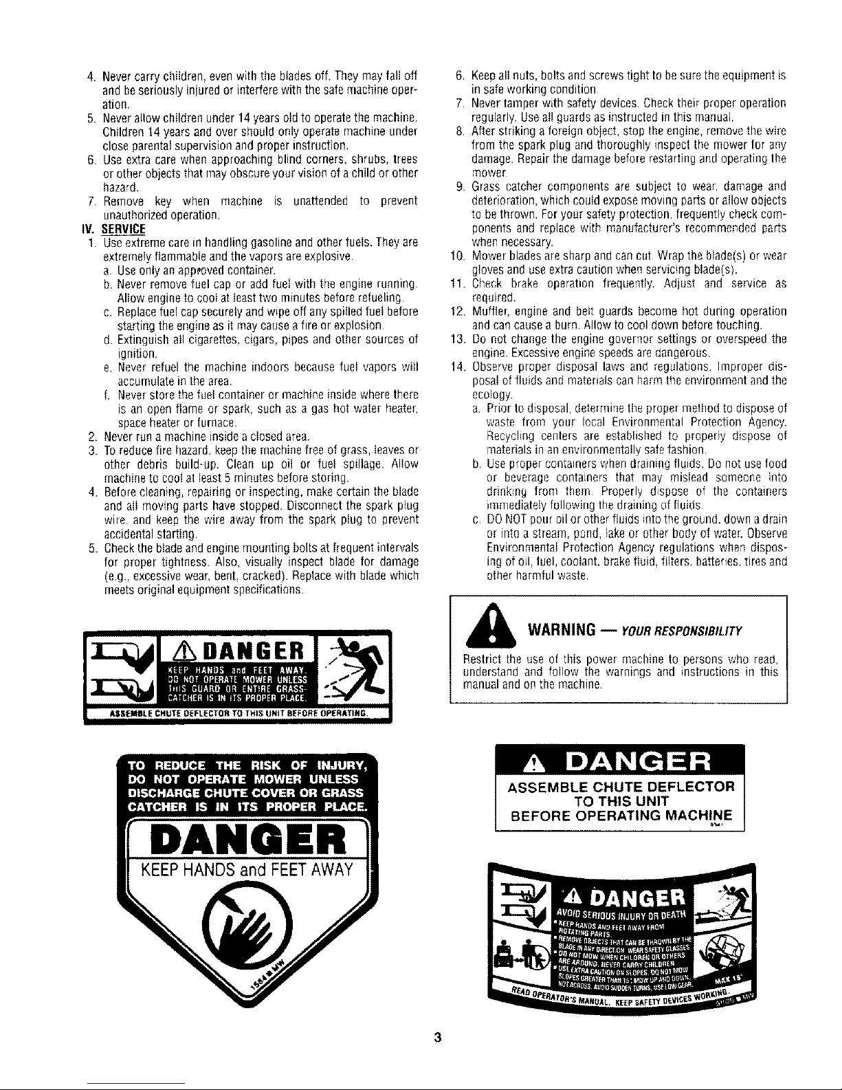
WARNING -- YOURRESPONSIBILITY
Restrict the use of this power machine to persons who read.
understand and foflow the warnings and instructions in this
manual and on the machine,
DANOBFI
Page 4
UNPACKING
TOREMOVEUNITFROMCRATE
1. Remove all screws from the top of the cr4te using
a 1/4" hex head socket or a flat blade scn;wdriver.
2. To remove ends, grasp top board on the _=nd,and
pull towards you in a downward motion.
3. Set panel aside to avoid tire punctures.
4. Repeat procedure for each side of the cr_te.
6. Loose parts (may include the owner's guide,
steering wheel, optional oil drain sleeve, battery
fluid, chute deflector, optional mulching kit, etc.)
are on the seat or in a box wrapped in plastic.
Carefully cut and remove the plastic wrap.
Remove the loose parts.
7. Make certain brake is released. Raise the deck
and push the unit off the skid.
5. Remove and discard plastic bag whicl covers
unit.
ASSEMI3LY INSTRUCTIONS
IMPORTANT: After assembly, service engine] E.
with gasoline, and check oil level as ins:ructed
l
in the separate engine manual packed wi :h your
unit. E
NOTE: Reference to right or left hand side of the
unit is observed from the driver's seat, fa,;ing for-
ward.
TOOLSREQUIREDFORASSEMBLY
(1) 1/4" socket wrench or flat blade screwdriv._r
(1) 1/2" wrench or socket wrench*
(1) 9/16" wrench or socket wrench
(2) 7/16" wrenches or socket wrenches
G,
NEVER connect or disconnect charger clips to
battery while charger is turned on as it can cause
sparks.
Keep all lighted materials (cigarettes, matches,
lighters) away from the battery as the hydrogen
gas generated during charging can be combusti-
ble.
As a further precaution, only charge the battery in
a well-ventilated area.
*Always shield eyes, protect skin and clothing
when working near batteries.
*If your steering wheel cap is square, you mu_t have a
socket wrench in order to install the steering _zheel.
BATTERYINFORMATION
WARNING
A. Battery acid must be handled with great care as
contact with it can burn and blister the nkin. It is
also advisable to wear protective clothing
(goggles, rubber gloves and apron) wher working
with it.*
g_
Should battery acid accidentally splatter into the
eyes or onto the face, rinse the affec ed area
immediately with clean cold water. If the'e is any
further discomfort, seek prompt medical attention.
C. If acid spills on clothing, first dilute it wth clean
water, then neutralize with a solution of ammonia/
water or baking soda/water.
D. Since battery acid is corrosive, do not p( ur it into
any sink or drain. Before discarding empt!' electro-
lyte containers, rinse them with a neutrali_ ing solu-
tion.
DANGER
Battery contains sulfuric acid. Refer to warning
at right. Antidote: EXTERNAL--Flush with water.
INTERNAL--Drink large quantities of water or milk.
Follow with milk of magnesia, beaten eggs or
vegetable oil. Call physician immediately. EYES:
Flush with cool water for at least 15 minutes, then
get prompt medical attention.
Since batteries produce explosive gases, keep
all lighted materials (cigarettes, lighters,
matches, etc.) away. Be sure to charge battery
only in well-ventilated areas. Make certain venting
path of battery drain tube (if equipped) is always
open.
KEEP BATTERIES
OUT OFTHE REACH OF CHILDREN!
4
Page 5
BATTERYIDENTIFICATION
CHARGE THE BATTERY after the 30 minute standing
period. Battery P/N 725-1705B--Charge at 2-3 amps
for one hour. Battery PiN 725-1707B and 725-
0453E--Charge at 6 amps for one hour.
NOTE: If you charge the battery at a Iower AMP rate,
use a hydrometer to make sure the battery is com-
pletely charged. The hydrometer should read 1,260
minimum at an electrolyte temperature of 60-110°E
DO NOT CHARGE AT MORE THAN 6 AMPS.
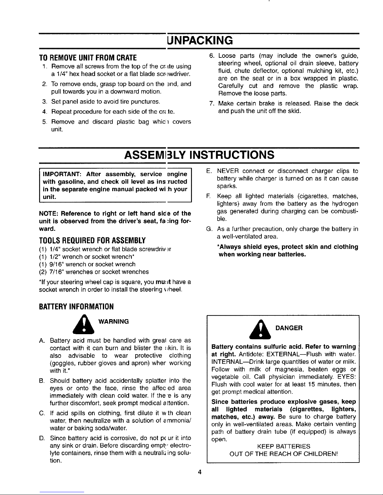
Type "A"
Type "B"
Compare the battery in your lawn tractor (located
under the seat) with the illustration above. Type "A"
batteries are activated and are ready to use. Type "B"
batteries must be filled with battery fluid (acid) and
charged before they are put into service. Follow the
instructions which apply to the battery in your lawn
tractor.
ACTIVATINGAND CHARGING THE BATTERY
(TYPE "B" BATTERY ONLY)
Do not activate battery (fill with battery acid) until
battery is actually placed in service. Be certain to
read previous battery warnings before activating
the battery.
1. Pivot the seat forward. Unhook the strap which
secures the battery (hook is on rear frame, under
fender). Disconnect the positive cable from the
positive terminal. Save the hardware for reassem-
bly.
2. Remove the battery from the lawn tractor, paying
attention to how the battery is placed in the unit,
and how the drain tube (attached to the battery) is
routed.
3, Activate the battery as instructed in the "Quick
Start" brochure included with the battery fluid.
Read instructions carefully.
NOTE: You can continue assembling the lawn tractor
while battery is standing for 30 minutes (after filling
with acid), and later while you are charging the battery.
IMPORTANT: To obtain the maximum life from your
battery, it MUST BE CHARGED prior to initial use.
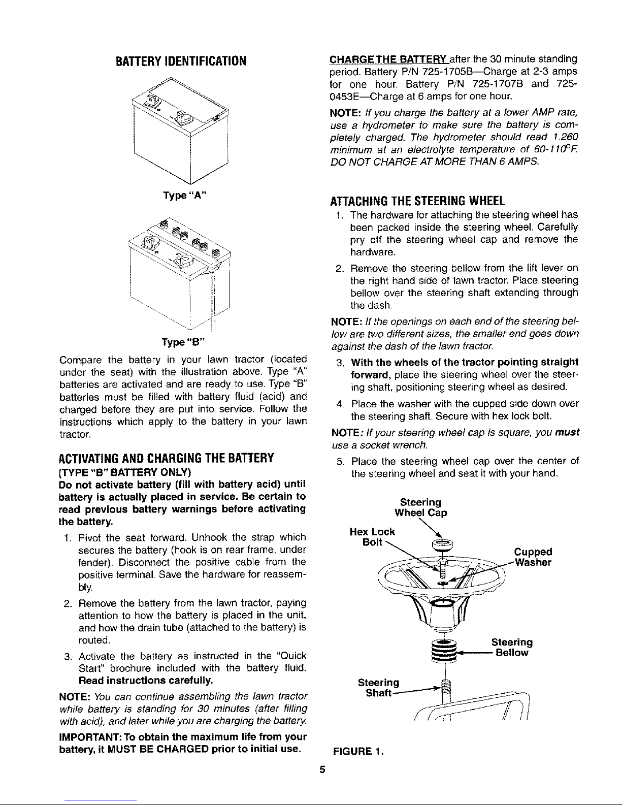
ATTACHINGTHE STEERING WHEEL
1. The hardware for attaching the steering wheel has
been packed inside the steering wheel, Carefully
pry off the steering wheel cap and remove the
hardware.
2. Remove the steering bellow from the lift lever on
the right hand side of lawn tractor. Place steering
bellow over the steering shaft extending through
the dash.
NOTE: tf the openings on each end of the steering bel-
low are two different sizes, the smaller end goes down
against the dash of the lawn tractor.
3. With the wheels of the tractor pointing straight
forward, place the steering wheel over the steer-
ing shaft, positioning steering wheel as desired.
4. Place the washer with the cupped side down over
the steering shaft. Secure with hex lock bolt.
NOTE: If your steering wheel cap is square, you must
use a socket wrench.
5. Place the steering wheel cap over the center of
the steering wheel and seat itwith your hand.
Steering
Wheel Cap
Hex Lock ""_
Bolt
Cupped
Steering
Shaft-
Steering
FIGURE 1.
5
Page 6
7 °[
FIGURE 2.
Screws
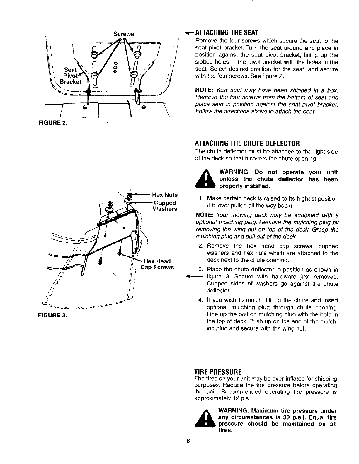
ATTACHINGTHESEAT
Remove the four screws which secure the seat to the
seat pivot bracket. Turn the seat around and place in
position against the seat pivot bracket, lining up the
slotted holes in the pivot bracket with the holes in the
seat. Select desired position for the seat, and secure
with the four screws. See figure 2.
NOTE: Your seat may have been shipped in a box.
Remove the four screws from the bottom of seat and
place seat in position against the seat pivot bracket.
Follow the directions above to attach the seat.
FIGURE 3.
\ Hax Nuts
(;upped
Vlashers
ATTACHINGTHECHUTEDEFLECTOR
The chute deflector must be attached to the right side
of the deck so that it covers the chute opening.
_ ARNING: Do not operate your unit
unless the chute deflector has been
properly instaned.
1. Make certain deck is raised to its highest position
(lift lever pulled all the way back).
NOTE: Your mowing deck may be equipped with a
optional mulching plug. Remove the mulching plug by
removing the wing nut on top of the deck. Grasp the
mulching plug and pull out of the deck,
2. Remove the hex head cap screws, cupped
washers and hex nuts which are attached to the
deck next to the chute opening.
Place the chute deflector in position as shown in
figure 3. Secure with hardware just removed.
Cupped sides of washers go against the chute
deflector.
If you wish to mulch, lift up the chute and insert
optional mulching plug through chute opening.
Line up the bolt on mulching plug with the hole in
the top of deck. Push up on the end of the mulch-
ing plug and secure with the wing nut.
TIRE PRESSURE
The tires on your unit may be over-inflated for shipping
purposes. Reduce the tire pressure before operating
the unit. Recommended operating tire pressure is
approximately 12 p.s.i.
&
WARNING: Maximum tire pressure under
any circumstances is 30 p,s.i, Equal tire
pressure should be maintained on all
tires,
Page 7
eckHanger =C_=
FIGURE 4.
Positive Terminal
Inside Rubber Boot)
U
Q
Negative
Cable Negative Battery
FIGURE 5. Terminal Compartment
FIGURE 6.
Baffery
Tr_
Reinforcement
Bracket
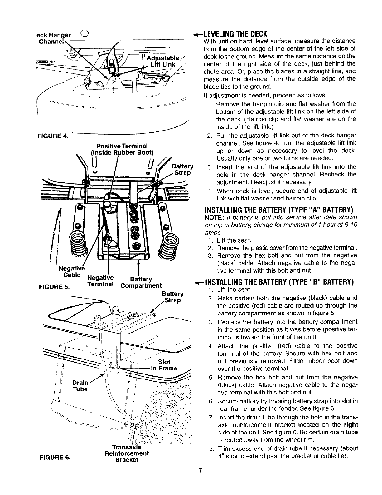
-,.,.-LEVELINGTHE DECK
With unit on hard, level surface, measure the distance
from the bottom edge of the center of the left side of
deck to the ground. Measure the same distance on the
center of the right side of the deck, just behind the
chute area. Or, place the blades in a straight line, and
measure the distance from the outside edge of the
blade tips to the ground.
If adjustment is needed, proceed as follows.
1. Remove the hairpin clip and flat washer from the
bottom of the adjustable lift link on the left side of
the deck. (Hairpin clip and flat washer are on the
inside of the lift link.)
2. Pull the adjustable lift link out of the deck hanger
channel. See figure 4. Turn the adjustable lift link
up or down as necessary to level the deck.
Usually only one or two turns are needed,
3. Insert the end of the adjustable lift link into the
hole in the deck hanger channel. Recheck the
adjustment. Readjust if necessary.
4. When deck is level, secure end of adjustable lift
link with fiat washer and hairpin clip.
INSTALLING THE BATTERY(TYPE "A" BATTERY)
NOTE: If battery is put into service after date shown
on top of battery, charge for minimum of 1 hour at 6-10
amps,
1. Lift the seat.
2. Remove the plastic cover from the negative terminal.
3. Remove the hex bolt and nut from the negative
(black) cable. Attach negative cable to the nega-
tive terminal with this bolt and nut.
Battery
INSTALLING THE BATTERY(TYPE "B" BATTERY)
1. Lift the seat.
2. Make certain both the negative (black) cable and
the positive (red) cable are routed up through the
battery compartment as shown in figure 5.
3. Replace the battery into the battery compartment
in the same position as it was before (positive ter-
minal is toward the front of the unit).
4. Attach the positive (red) cable to the positive
terminal of the battery, Secure with hex bolt and
nut previously removed. Slide rubber boot down
over the positive terminal.
5. Remove the hex bolt and nut from the negative
(black) cable. Attach negative cable to the nega-
tive terminal with this bolt and nut.
6, Secure battery by hooking battery strap into slot in
rear frame, under the fender. See figure 6,
7. Insert the drain tube through the hole in the trans-
axle reinforcement bracket located on the right
side of the unit. See figure 6. Be certain drain tube
is routed away from the wheel rim.
8. Trim excess end of drain tube if necessary (about
4" should extend past the bracket or cable tie).
Page 8
Choke / '
Clutch-Brake
Pedal
CONTROLS
Ignition
Switch
Switch
(Optional)
FIGURE 7.
_. Optional)
Shift Lcver
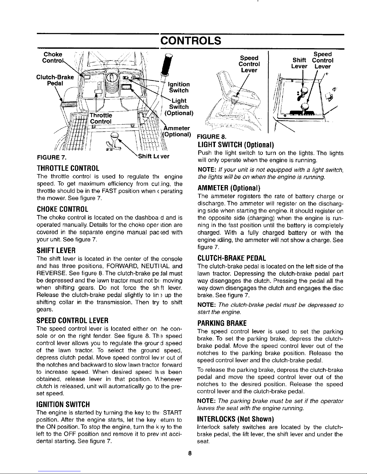
THROTTLECONTROL
The throttle control is used to regulate th_ engine
speed. To get maximum efficiency from cul:ing, the
throttle should be in the FAST position when cperating
the mower. See figure 7.
CHOKECONTROL
The choke control is located on the dashboard and is
operated manually. Details for the choke oper _tionare
covered in the separate engine manual pacced with
your unit. See figure 7.
SHIFT LEVER
The shift lever is located in the center of the console
and has three positions, FORWARD, NEUTI{AL and
REVERSE. See figure 8. The clutch-brake pe Jal must
be depressed and the lawn tractor must not b_ moving
when shifting gears. Do not force the shft lever.
Release the clutch-brake pedal slightly to lin ; up the
shifting collar in the transmission. Then try to shift
gears.
SPEEDCONTROLLEVER
The speed control lever is located either on :he con-
sole or on the right fender. See figure 8. Th_= speed
control lever allows you to regulate the grourd speed
of the lawn tractor. To select the ground speed,
depress clutch pedal. Move speed control lev,_r out of
the notches and backward to slow lawn tractor forward
to increase speed. When desired speed his been
obtained, release lever in that position. _Ahenever
clutch is released, unit will automatically go to the pre-
set speed.
IGNITIONSWITCH
The engine is started by turning the key to th_ START
position. After the engine starts, let the key eturn to
the ON position. To stop the engine, turn the k ;y to the
left to the OFF position and remove it to prey ;nt acci-
dental starting. See figure 7.
Speed
Control
Lever
Speed
Shift Control
Lever Lever
FIGURE 8.
LIGHTSWITCH(Optional)
Push the light switch to turn on the lights. The lights
will only operate when the engine is running.
NOTE: If your unit is not equipped with a light switch,
the lights will be on when the engine is running.
AMMETER (Optional)
The ammeter registers the rate of battery charge or
discharge. The ammeter will register on the discharg-
ing side when starting the engine. It should register on
the opposite side (charging) when the engine is run-
ning in the fast position until the battery is completely
charged. With a fully charged battery or with the
engine idling,the ammeter will not show a charge. See
figure 7.
CLUTCH-BRAKE PEDAL
The clutch-brake pedal is located on the left side of the
lawn tractor. Depressing the clutch-brake pedal part
way disengages the clutch. Pressing the pedal all the
way down disengages the clutch and engages the disc
brake. See figure 7.
NOTE: The clutch-brake pedal must be depressed to
start the engine.
PARKINGBRAKE
The speed control lever is used to set the parking
brake. To set the parking brake, depress the clutch-
brake pedal. Move the speed control lever out of the
notches to the parking brake position. Release the
speed control lever and the clutch-brake pedal
To release the parking brake, depress the clutch-brake
pedal and move the speed control lever out of the
notches to the desired position. Release the speed
control lever and the clutch-brake pedal.
NOTE: The parking brake must be set if the operator
leaves the seat with the engine running.
INTERLOCKS(Not Shown)
Interlock safety switches are located by the clutch-
brake pedal, the lift lever, the shift lever and under the
seat.
8
Page 9

Beforethe enginewill start,the clutch-brakepedal
mustbedepressedallthewayandtheliftlevermust
beintheBLADESOFFposition.
Beforetheunitcanbe shiftedinto reverseor if the
operatorleavestheseat,theliftlevermustbeinthe
BLADESOFFposition.
INDICATOR LIGHTS (Optional)
If your unit is equipped with indicator lights, two or
three indicator lights are located in the dash panel. If a
light illuminates when attempting to start the unit, pro-
ceed as follows.
CLUTCH--Depress the clutch pedal.
PTO--Place lift lever in the BLADES OFF position.
OiL (Vanguard Engines Only)--Check the crankcase
oil level, and add oil as required.
CUTTING CONTROLS
A. LIFT LEVER
The lift lever is used to raise and lower the cutting deck
and to engage and disengage the blades. Pulling it all
the way back and locking it disengages the blades.
NOTE: The lift lever must be in the BLADES OFF posi-
tion when starting the engine, when shifting into reverse
and if the operator leaves the seat. See figure 9.
OPERATION
WARNING
AVOID SERIOUS INJURY OR DEATH
• GOUPAND DOWNSLOPES,NOTACROSS,• AVOIDSUDDENTURNS.
• DONOTOPERATETHE UNITWHERE IT COULDSLiP OR TiP.
• IF MACHINE STOPS GOING UPHILL, STOP BLADE(S) AND BACK
DOWNHILLSLOWLY.
• DONOTMOWWHENCHILDRENOROTHERSAREAROUND.
• NEVERCARRYCHILDREN.
• LOOKDOWNANDBEHINDBEFOREANDWHILEBACKING.
• KEEPSAFETYDEVICES(GUARDS, SHIELDS,ANDSWITCHES) IN
PLACEANDWORKING.
• REMOVEOBJECTSTHATCOULDBETHROWNBYTHEBLADE(S),
• KNOWLOCATIONANDFUNCTIONOFALLCONTROLS.
• BESUREBLADE(S) ANDENGINEARESTOPPEDBEFOREPLACING
HANDSORFEETNEARBLADE(S).
• BEFORELEAVINGOPERATOR'SPOSITION,DISENGAGEBLADE(S),
PLACETHESHIFTLEVERINNEUTRAL,ENGAGEBRAKELOCK,SHUT
ENGINEOFFANDREMOVEKEY
READ OPERATOR'S MANUAL
GAS AND OIL FILL-UP
NOTE: To open the hood, simply lift up on both sides
of the hood.
Check oil level and add if necessary. Service the
engine with gasoline as instructed in the sepa-
rate engine manual packed with your tractor.
Read instructions carefully,
IMPORTANT: Your tractor is shipped with oil; how-
ever, you must check the oil level before operating.
Be careful not to overfill.
o Deck
Lift Indicator •
, (Option_ \_:a Jk--'_
%
FIGURE 9.
B. DECK LIFT INDICATOR (Optional Equipment)
If so equipped, the deck lift indicator marks the posi-
tion being used for the lift lever. Select the lift lever
position desired, press the indicator lever outward,
move it to the position immediately below the lift lever
and release the indicator lever. See figure 9.
C. SETTING THE CU'I-rlNG HEIGHT
1. Select the position for the lift lever which gives the
desired cutting height. Move the deck lift indicator
(if so equipped) so that the lift lever can be
returned to the same position after it is raised.
2. Move the deck wheels (if so equipped) to the hole
location so the wheels are 1/4 to 1/2 inch above
the ground.
WARNING: Never fill fuel tank indoors,
with engine running or while engine is
hot.
STARTINGTHEENGINE
1. Depress the clutch-brake pedal and set the park-
ing brake.
2. Place the lift lever in the BLADES OFF position.
See figure 9.
IMPORTANT: This unit is equipped with a safety
interlock system for your protection. The purpose of
the safety interlock system is to prevent the engine
from cranking or starting unless the clutch-brake pedal
is depressed and the lift lever is in the BLADES OFF
position. In addition, the lift lever must be in the
BLADES OFF position when the unit is put into
reverse or the engine will shut off. If the operator
leaves the seat with the lift lever engaged and/or with-
out setting the parking brake, the engine will shut off.
WARNING: Do not operate the lawn
tractor if the interlock system is malfunc-
tioning because it is a safety device,
designed for protection.
Page 10

3. Set the throttle control in the FAST posi ion, See
figure 7.
4. Pull out choke knob to choke engine ia warm
engine may not require choking).
5. Turn the ignition key to the START positk n. When
the engine is running, let the key return t_Jthe ON
position. See figure 7.
6. Push choke knob in gradually. Move th_ throttle
control to desired engine speed.
STOPPINGTHEENGINE
Turn the ignition key to the left to the OFF position.
Remove the key to prevent accidental starting
IMPORTANT: If you strike a foreign object, stop the
engine. Remove wire from spark plug, th)roughly
inspect the unit for any damage, and re3air the
damage before restarting and operating the iTower.
NOTE: tf any problems are encountered, ret =.rto the
Trouble Shooting Guide on page !9.
OPERATINGTHELAWNTRACTOR
1, Move throttle control to full throttle to prevent
strain on the engine and to operate th_ cutting
blades.
2. Place the shift lever in either the FORWARD or
REVERSE position.
,_ WARNING: Look to the before back-
rear
ing up.
3. Release the parking brake by depres_;ing the
clutch-brake pedal, pressing outward on the
speed control lever and moving to desir_,d posi-
tion. Use first speed position when oper_ ting the
lawn tractor for the first time.
4. Release clutch-brake pedal slowly to put unit into
motion.
5. The lawn tractor is brought to a stop by depress-
ing the clutch-brake pedal.
NOTE: When operating the un# initially, thera will be
little difference between the highest two spe, _,dsuntil
after the belts have seated themselves into th__pulleys
during the break-in period.
Be sure that the lawn is clear of stones, sticks wire, or
other objects which could damage lawn m3wer or
engine. For best results and to insure more ev,;n grass
distribution, do not mow when lawn is excessi_ ely wet.
&
WARNING: Before leaving the op.=rator's
position for any reason, diseng=lge the
blades, place the shift lever in neutral,
engage the parking brake, shut en ;line off
and remove the key.
When stopping the unit to empty a grass bag, etc.,
follow the instructions above. This procedure will also
eliminate "browning" the grass, which is caused by hot
exhaust gases from a running engine.
If unit stalls with speed control in high speed, or if unit
will not operate with speed control lever in a low speed
position, proceed as follows.
1. Place shift lever in NEUTRAL.
2. Restart engine.
3. Place speed control lever in high speed position.
4. Release clutch-brake pedal fully.
5. Depress clutch-brake pedal.
6. Place speed control lever in desired position.
7. Place shift lever in either FORWARD or
REVERSE, and follow normal operating proce-
dures.
OPERATINGTHE CUTTING BLADES
The cutting blades may be engaged while the lawn
tractor is moving or standing still. DO NOT engage the
cutting blades abruptly as the sudden belt tension on
the pulley may cause the engine to stall.
_i WARNING: Keep feet and hands away
from the discharge opening, the blades or
any part of the deck. When the unit is
used for other than mowing operations,
the blade drive should be disengaged.
Move the lift lever into the BLADES OFF position to
raise the deck and disengage the blades.
GRASSCOLLECTORAVAILABLE
GRASS COLLECTOR model 190-063-000 is available
as optional equipment for the lawn tractors with 36",
38" or 42" decks. Grass collector model 190-103-000
is available for lawn tractors with 46" decks.
WARNING: The mower should not be
operated without the entire grass catcher
or chute deflector in place.
NOTE: Under normal usage bag material is subject to
wear, and should be checked periodically. Be sure to
use only factory authorized replacement bag.
10
ADJUSTMENTS
SEATADJUSTMENT
The seat may be adjusted to different positions. Refer
to seat installation section of assembly instructions.
DECKLEVELINGADJUSTMENT
If an uneven cut is obtained, the deck may be leveled
by following instructions at end of assembly section.
Page 11

CUTTINGDECKENGAGEMENTADJUSTMENT
The cutting deck engagement may be adjusted to
make certain deck is disengaged when lift lever is in
lhe BLADES OFF position, Correct adjustment as
bllows.
With the engine off, place the lift lever in the highest
cutting position (first position). Remove the cotter pin
and flat washer which secure the disengagement rod
to the stabilizer shaft assembly. Shorten the rod by
threading it in until the ferrule is against the back of the
slot in the lift shaft assembly, and the rod lines up with
the hole in the stabilizer shaft. For more belt tension
the disengagement rod must be lengthened. To
decrease belt tension the disengagement rod must be
shortened.
Check the adjustment by placing the lift lever in the
BLADES OFF position. The deck should move up and
forward, allowing the belt to become loose. Start and
test for disengagement, Repeat procedure as neces-
sary,
Stabilizer Shaft
Assembly isengagement Rod
Flat Washer
Hairpin Clip
Stabilizer Shaft
Assembly
36" and
38" Decks
_._Disengagement R°_
FlatWasher [ 42" and
Hairpin Clip 146" Decks
FIGURE 10.
SPEEDCONTROLADJUSTMENT(See figure11)
NOTE: When operating the unit initially or after replac-
ing the belts, there will be little difference between the
highest two speeds until after the belts have gone
through a break-in period and have seated themselves
into the pulleys.
If the full range of speeds cannot be obtained on your
unit, adjust the speed control as follows.
1. Adjust the speed control lever by pushing the
clutch-brake pedal forward until the stop on the
brake rod is against the frame. See figure !3.
Have another person hold the pedal in this
position as you make the following adjustment.
Place the speed control lever in parking brake
position. Remove the hairpin clip and flat washer,
and adjust the ferrule on the rod so it is against
the back end of the slot. See figure 11. Then
lengthen rod one more turn. Reassemble and
secure with the fiat washer and hairpin clip.
2, Adjust the speed control link as follows to obtain
the correct neutral adjustment.
A. Start the engine.
B Place the shift lever in Neutral position.
C. Place the speed control lever in high speed
position.
D. Release the clutch-brake pedal completely.
then slowly depress the pedal all the way (to
park position). Hold the pedal in this position.
E. Turn the engine off.
E After engine stops completely, release the
clutch-brake pedal.
G. Position speed control lever as follows.
7-speed units--Place speed control lever in
second position,
6-speed units--Place speed control lever
between first and second position (hold in this
position).
5-speed units--Place speed control lever in
first position.
H. Remove the cotter pin and flat washer which
secures the speed control link to the variable
speed torque bracket assembly.
I. Push the clutch-brake pedal backward by
hand as far as it will go using light pressure.
Hold it in this position as you thread the speed
control link in or out of the ferrule until it lines
up with the pin on the variable speed torque
bracket assembly,
J. Secure speed control link to variable speed
torque bracket assembly with flat washer and
cotter pin.
11
Page 12

Back of
Speed Control
Lever
A
Ferrule
Speed
Rod
Variable Speed
Torque Bracket
Assembly
Slot
Hair "
Clip and """
Flat Washer , _.
FIGURE 11.
Speed
Con rol
Speed
Control
Link
/
Loosen
Hex Bolt
Slot
_;hift
Lever
NEUTRAL ADJUSTMENT
1. Place the transmission in neutral. (The unit will
move freely when pushed forward and backward
with the parking brake released.)
2, Loosen the bolt which secures the shift lever
assembly to the shift lever link, See figure 12.
3. Place the shift lever in the neutral slot. See figure
12_
4. Tighten the bolt to 13 foot pounds.
FIGURE 12.
12
Page 13

WHEELADJUSTMENT
The caster (forward slant of the king pin) and the
camber (tilt of the wheels out at the top) require no
adjustment, Automotive steering principles have been
used to determine the caster and camber on the
tractor. The front wheels should toe-in 1/8 inch.
Some units have adjustable tie rods so the toe-in can
be adjusted. To adjust the toe-in on these units, pro-
ceed as follows.
1. Remove the hex nut and lock washer, and drop
the tie rod end from the wheel bracket. See figure
13.
2. Loosen the hex jam nut on tie rod.
3. Adjust the tie rod assembly for correct toe-in.
Tie
Rod
X
Bracket
Nut
Tie
End
\ Lock Washer
FIGURE 13.--Units with adjustable tie rods
Dimension "B" should be approximately 1/6" less than
Dimension "A" See figure 14.
A,) To increase Dimension "B,"screw tie rod into tie
rod end.
B.) To decrease Dimension "B," unscrew tie rod from
tie rod end.
C.) Reassemble tie rod. Check dimensions. Readjust
if necessary.
I: A
__ Front
I' B
(1/8" LessThan A)
-I
$
.1
FIGURE 14.--Units with adjustable tie rods
CARBURETORADJUSTMENT
&
WARNING: If any adjustments are made to
the engine while the engine is running
(e.g. carburetor), disengage all clutches
and blades. Keep clear of all moving
parts. Be careful of heated surfaces and
muffler.
Minor carburetor adjustment may be required to
compensate for differences in fuel, temperature,
altitude and load.To adjust the carburetor, refer to the
separate engine manual packed withyour unit.
NOTE: A dirty air cleaner will cause an engine to run
rough. Be certain air cleaner is clean and attached to
the carburetor before adjusting carburetor.
BRAKEADJUSTMENT(Seefigure15)
The brake is located by the right rear wheel inside the
frame. During normal operation of this machine, the
brake is subject to wear and will require periodic
examination and adjustment.
WARNING: Do not have the run-
engine
ning when you adjust the brake.
To adjust the brake, adjust the nut so the brake starts
to engage when the brake lever is 1/4" to 5/16" away
from the axle housing.
FIGURE 15.
B
Lever
&
LUBRICATION
WARNING: Always stop engine and dis-
connect spark plug wire before cleaning,
lubricating or doing any kind of work on
lawn tractor.
13
Page 14

STEERINGGEARS
Lubricate teeth of steering gears with autc_notive
multi-purpose grease after every 25 hours of op ,=ration
or once a season. See figure 16.
STEERINGSHAFT
Lubricate steering shaft at least once a seascn with
light oil.
Gears
The spark plug(s) should be cleaned and the gap
reset once a season. Spark plug replacement is
recommended at the start of each mowing season;
check engine manual for correct plug type and gap
specifications.
Maintain engine oil as instructed in the separate
engine manual packed with your unit. Read and follow
instructions carefully.
Optional Oil Drain Sleeve
Your lawn tractor may have a plastic oil drain sleeve
packed with the loose parts for your convenience in
draining oil from the crankcase. To drain the oil, snap
small end of oil drain sleeve onto oil sump. See figure
17. Remove drain plug and drain oil into a suitable
container.
Oil
FIGURE 16.
TRANSAXLE
The transaxle is lubricated at the factory and dces not
require checking. If disassembled for any r,_ason,
lubricate with 10 oz. of Shell grease, part numb__r737-
0148.
WHEELS
The front wheels may be provided with grease l ittings.
The rear wheels must be removed from the exle for
lubrication. Lubricate both front and rear wh_els at
least once a season with automotive multi-p ]rpose
grease.
PIVOTPOINTS
Lubricate all pivot points with light oil at least ,_nce a
season.
MAINTENANCE
m
WARNING: Disconnect the spar_ plug
wire(s) and ground against the ,;ngine
before performing any adjust nents,
repairs or maintenance.
TROUBLE SHOOTING
Refer to the chart on page 19 for trouble stooting
engine problems.
ENGINE
Refer to the separate engine manual for _pngine
maintenance instructions.
Service air cleaner every 10 hours under _ormal
conditions. Clean every few hours under exl'emely
dusty conditions.To service the air cleaner, refe to the
separate engine manual packed with your unit.
Oil Drain
Sleeve
FIGURE 17.
FUELFILTER
Your unit is equipped with a replaceable in-line fuel
filter. Replace filter whenever contamination or dis-
coloration is noticed. Order replacement filter through
your authorized engine service dealer.
CLEANINGENGINEANDDECK
Any fuel or oil spilled on the machine should be wiped
off promptly. Grass, leaves, and other dirt must net be
left to accumulate around the cooling fins of the engine
or on any part of the machine.
Clean the underside of the deck after each mowing.
CUTTING BLADES
A, Removal for Sharpening or Replacement
&
WARNING: Be sure to disconnect and
ground the spark plug wire(s) and remove
ignition key before working on the cutting
blade to prevent accidental engine start-
ing. Protect hands by using heavy gloves
or a rag to grasp the cutting blades.
1. Remove the hex flange nut which holds the blade
to the blade spindle.
2. Remove the blade from the spindle.
14
Page 15

B.Sharpening
Remove the cutting blades by following the directions
ofthe preceding section.
When sharpening the blades, follow the original angle
of grind as a guide. It is extremely important that each
cutting edge receives an equal amount of grinding to
prevent an unbalanced blade. An unbalanced blade
will cause excessive vibration when rotating at high
speeds, may cause damage to the mower and could
break, causing personal injury.
The blade can be tested for balance by balancing it on
a round shaft screwdriver. Remove metal from the
heavy side until it balances evenly.
C. Reasaembly
When replacing blades, be sure to install the blade
with the side of the blade marked "Bottom" (or with
part number) facing the ground when the mower is in
the operating position. Carefully align "star" on blade
with "star" on spindle. Secure with hex flange nut.
Blade Mounting Torque
Hex Flange Nut: 1080 in. lb. rain., 1230 in. lb. max.
To ensure safe operation of your unit, all nuts and bolts
must be checked periodically for correct tightness.
BATTERYCAREANDMAINTENANCE
(TYPE "A" BATTERY)
Type "A" batteries are sealed and are maintenance free.
BATTERYCAREANDMAINTENANCE
(TYPE"e" BATTERY)
CHECK FLUID LEVEL
Check fluid level inside each cell of the battery every
two weeks and before and after charging. Always keep
level between maximum and minimum fill level.
Add only distilled water. Never add additional acid
or any other chemicals to the battery after initial
activation.
NOTE: After operating the lawn tractor for a long
period of time, check the fluid level in the battery as it
can overheat and lose fluid.
CHARGING THE BATTERY (ALL BATTERIES)
The engine is equipped with an alternator which
charges battery when tractor is operated. Under
normal conditions, the battery only needs to be
charged before, during and after oft-season storage.
Follow the instructions under "Oft-Season Storage."
To charge the battery: Battery P/N 725-1705B_
Charge at 2-3 amps for one hour. Battery P/N 725-1707B
and 725-0453E_harge at 6 amps for one hour.
REMOVING / INSTALLING / JUMP STARTING
&
WARNING: When removing or installing
the battery, follow these instructions to
prevent the screwdriver from shorting
against the frame.
Removing the Battery: Disconnect negative cable
first, then positive cable.
Installing the Battery: Connect positive cable first,
then negative cable.
Jump Starting
1. First, connect end of one jumper cable to the
positive terminal of the good battery, then the
other end to the positive terminal of the dead
battery.
2. Connect the other jumper cable to the negative
terminal of the good battery, then to the FRAME
OF THE UNIT WITH THE DEAD BATTERY.
_b ARNING: Failure to use this procedure
could cause sparking, and the gas in
either battery could explode.
CLEAN THE BATTERY
Clean the battery by removing it from the unit and
washing with a baking soda and water solution. If nec-
essary, scrape the battery terminals with a wire brush
to remove deposits. Coat terminals and exposed wir-
ing with grease or petroleum jelly to prevent corrosion.
BATTERY FAILURES
Some common causes for battery failure are: incorrect
initial activation, lack of water, adding chemicals other
than water after initial activation, undercharging, over-
charging, corroded connections, freezing. These
failures do not constitute warranty.
TIRES
Recommended operating tire pressure is approxi-
mately 12 p.s.i. Maximum tire pressure under any
circumstances is 30 p.s.i. Equal tire pressure should
be maintained on all tires.
When installing a tire to the rim, be certain rim is clean
and free of rust. Lubricate both the tire and rim
generously. Never inflate to over 30 p.s.i, to seat beads.
_1) WARNING: Excessive pressure (over 30
p.s.i.) when seating beads may cause tire/
rim assembly to burst with force sufficient
to cause serious injury.
BELTREMOVALAND REPLACEMENT
WARNING: Disconnect the spark plug
wire(s) and ground it against the engine.
Block the wheels of the unit.
NOTE: Figures 18, 22 and 23 are shown with the unit
tipped up for clarity. It is not necessary to tip the unit to
remove the belts.
However, ff tipping the unit is desired, remove the
battery from the unit. To prevent gasoline leakage,
drain the gasoline, or remove the fuel tank cap, place a
thin piece of plastic over the neck of the fuel tank and
screw on the cap. Be certain to remove the plastic
when finished changing the belts. Block unit securel_
15
Page 16

DECK BELT (38" and 42" DECKS)
1. Place the lift lever in the engaged (all tie way
forward) position.
2. Disconnect the spring which is attached to a
bracket on the transaxle, inside the richt rear
wheel. Use a spring puller or other euitabk tool.
NOTE: When reassembling, make certain bah keeper
pins are assembled in the same locations fror _ which
they were removed. See figure 18.
Belt Keeper Pins
Pulley
FIGURE 18,
3. Place the lift lever inthe BLADES OFF po,'.ition.
4. Remove the belt keeper pins from th_ lower
frame. See figure 18.
5. Unhook the deck belt from the engine pulk .y.
6. Place the lift lever in the engaged (all l'_e way
forward) position.
7. Disconnect the stabilizer plate from the s:abilizer
shaft assembly by removing the hairpin c ips and
flat washers and sliding out the rod. Refer 1_figure
12.
8. Disconnect the six deck links by removing the
hairpin clips and flat washers.
9. Place the lift lever in the BLADES OFF po=ition.
10. Slide the deck from beneath the lawn tract )r.
11. Remove the belt guards at each deck p dley by
removing the self-tapping screws. See figu re 19.
Stabilizer Plate Belt
Guard
Self-Tapping
Screws
12. Remove and replace the belt, reassemble follow-
ing the instructions in reverse order.
DECK BELTS (46" DECK)
1. Place the lift lever in the engaged (all the way
forward) position.
2. Disconnect the spring which is attached to a
bracket on the transaxle, inside the right rear
wheel. Use a spring puller or other suitable tool.
NOTE: When reassembling, make certain belt keeper
pins are assembled in the same locations from which
they were removed. See figure 18.
3. Place the lift lever in the BLADES OFF position.
4. Remove the belt keeper pins from the lower
frame. See figure 18.
5. Unhook the deck belt from the engine pulley.
6. Place the lift lever in the engaged (all the way
forward) position.
7. Disconnect the stabilizer plate from the stabilizer
shaft assembly by removing the hairpin clips and
flat washers and sliding out the rod. Refer to figure
12.
8. Disconnect the six deck links by removing the
hairpin clips and flat washers.
9. Place the lift lever in the BLADES OFF position.
10. Slide the deck from beneath the lawn tractor.
11. Remove the top deck drive belt by lifting up on the
stabilizer plate, and slipping belt off the pulley.
12. Remove the belt cover at the two ouside deck pul-
leys, by removing the self-tapping screws.
13. Release the tension on the spring loaded idler by
pushing the idler toward the rear of the deck.
14. Remove the belt from around the idler pulleys,
and remove from the three deck pulleys.
15. Reassemble new belts, following instructions in
reverse order.
FIGURE 19.
Belt Guard
REAR DRIVE BELT
1. Place shift lever in neutral position. Unscrew the
shift knob and the speed control knob (if located
on the console). Remove the two truss head
screws which secure the transmission cover. See
figure 20A.
2. Lift the transmission cover. Unplug the safety wire
from beneath the transmission cover. See figure
20B. Remove transmission cover.
16
Page 17

AI
Shift
Knob
Truss
Head Screws
4. Unhook the deck belt from the engine pulley.
5. Remove the center bolt, lock washer and flat
washer, and let the engine pulley drop down so
the belt is past the belt guards.
Center Bolt
Lock Washer
Flat Washer
FIGURE 20.
3. Push the idler pulley toward the right side of the
unit. Lift the belt over the idler pulley. See figure
21.
4. Remove the belt from the variable speed pulley.
5. Remove the two bolts which hold the shift lever
bracket to the frame on the left side of the unit.
Swing the bracket toward the right so the belt can
be removed from the transmission pulley. See
figure 21.
6. Replace belt, and reassemble in reverse order.
7. Adjust the speed control as instructed in adjust-
ment section.
Transmission
Pulley
Shift Lever Bracket
Hex Bolt
FIGURE 22.
6. Place the clutch-brake pedal in park position,
7. Push forward on the variable speed pulley, lift the
belt off the engine pulley, and remove the belt
from the pulley.
8. Release the clutch-brake pedal. Using the pedal
to move the variable speed pulley as necessary,
lift the belt up and off the variable speed pulley.
NOTE: When reassembling, make certain belt is
inside the pins. See figure 23.
Speed
Idlel
Pulley
FIGURE 21.
Speed Pulley
Rear
Belt
FRONT DRIVE BELT
1. To remove the front drive belt, first remove the
rear drive belt from the idler pulley and variable
speed pulley.
2. Place the lift lever in the BLADES OFF position.
3. Remove the belt keeper pins from the engine
pulley belt guard. Refer to figure 18.
NOTE: Make certain belt keeper pins are reassembled
as shown in figure 18.
: Pins
. __ ,d
FIGURE 23.
9. Reassemble with a new belt, following instructions
in reverse order.
10. Adjust the speed control as instructed in adjust-
ment section.
17
Page 18

OFF-SEASON STORAGE 4.
If the machine is to be inoperative for a perioc longer
than 30 days, prepare for storage as follows.
1. Clean the engine and the entire unit thoroL ghly.
2. Lubricate all lubrication points. Wipe the entire
machine with an oiled rag to protect the su faces.
3. Refer to the engine manual for correct engine
storage instructions. The engine must b ; com-
pletely drained of fuel to prevent gum c_=posits
from forming on essential carburetor pairs, fuel
lines and fuel tanks.
Charge battery fully. The battery loses some of
its charge each day when the unit is not used.
NEVER store battery without a full charge.
Recharge battery before returning to service or
every two months, whichever occurs first.
5. When storing unit for extended periods, discon-
nect battery cables. Removing battery from unit is
recommended.
6. Store unit in a clean, dry area. Do not store next to
corrosive materials, such as fertilizer.
NOTE= When storing any type of power equipment in
an unventilated or metal storage shed, care should be
taken to rustproof the equipment. Using a light oil or
silicone, coat the equipment, especially any chains,
springs, bearings and cables.
18
Page 19

TROUBLE SHOOTING GUIDE
_ROBLEM POSSIBLE CAUSE(S) CORRECTIVE ACTION
-_'nginewill not Safety switch button There are two switches in the starting circuit of your unit:the clutch pedal switch and the deck lift lever
',rank not depressed switch, Make certain the actuator is fully depressing the buttons on each switch,
Battery installed The battery must be installed with negative terminal attached to black ground wire. Negative terminal
incorrectly is identified at the post by "NEG", "N" or "-". The positive terminal, identified by "POS", "P" or "+", must
be attached to the big red wire which goes to the solenoid.
Battery is dead or weak Check fluid level in battery. If fluid is low, fill between maximum and minimum fill lines with water.
Charge with 6 amp charger until fully charged.
Blown fuse or circuit Replace fuse with automotive type fuse. Fuses seldom fail without a reason. The problem must be
breaker corrected. Check for loose connections in the fuse holder. Replace fuse holder if necessary. A dead
short may be in the cranking or charging circuit where the insulation may have rubbed through and
exposed the bare wire. Replace the wire or repair with electrician's taps if the wire strands have not
been damaged.
Note: Look for a wire pinched between body panels, burned by the exhaust pipe or muffler or rubbed
against a moving part.
:ngine cranks Throttle or choke not in Check owner's guide for correct position for throttle control and choke for starting.
_utwill not start starting position
No spark to spark plug Spark plug lead disconnected. Connect lead. Place spark plug lead away from engine block about
1/8". Crank engine. There should be a spark. If not, have engine repaired at authorized engine service
dealer.
Faulty spark plug. To test, remove spark plug. Attach spark plug lead to spark plug. Ground the spark
plug body against the engine block. Crank the engine. The spark plug should fire at the electrode.
Replace if itdoes not.
No fuel to the carburetor Gasoline tank empty. Fill.
Fuel line or in-line fuel filter plugged. Remove and clean fuel line. Replace filter if necessary.
Air filter dirty If the air cleaner is dirty, the engine may not start. Clean or replace as recommended by the engine
manufacturer.
:ngine smokes Engine loses crankcase Dipstick not seated or broken. Replace defective part.
vacuum Engine breather defective. Replace.
:xcessive Bent or damaged blade Stop engine immediately. Check all pulleys, blade adapters, keys and bolts for tightness and
ibration spindle damage. Tighten or replace any damaged parts.
Bent blade Stop engine immediately. Replace damaged blade. Only use original equipment blades.
_]ower will not Engine speed low Throttle must be set at full throttle.
lischarge Speed selection Use lower ground speed. The slower your ground speed, the better the quality of cut.
_rassor leaves Blades short or dull Sharpen or replace blades (uncut strip problem only).
neut strips
he above steps fail to correct the problem, take the unit to your local authorized service dealer for repair.
19
Page 20

OPTIO! IAL EQUIPMENT
At the time of manufacture of lawn tractor, the following optional equipment is
available.
NOTE: These lawn tractors are not designed for ground-engaging equipment
(tillers, plows, etc.).
Description Model No.
40" Two Stage $ now Thrower
42" Dozer Blade
Mulching Kit for }8"/42" Deck
Mulching Kit for J,6"Deck
Twin Bag Grass 0ollector for 36", 38"
and 42" Side I)ischarge Decks
Twin Bag Grass Collector for 46"
190-621-000
190-620-000
190-112-000
190-118-000
190-063-000
Side Discharg _ Decks
Front Counterw_ ight
Tire Chains---1E x 8.5
1_ x9.5
2C x8
2C xl0
31 Lb. Wheel W_tights
Gang Reel (Set 3fthree)
38" Lawn Sweef ,er
Heavy Duty Law n Roller
Heavy Duty Dun ip Cart
Tine De-Thatch_ _r
190-103-000
190-745-000
190-754-000
190-657-000
190-658-000
190-915-000
190-215-000
45-0195*
45-0222*
45-0179*
45-0171 *
45-0186*
*Available through your local dealer or from Agri-Fab Inc., 303 W. Raymond
Street, Sullivan, Illinois 61951.
2O
Page 21

USE THIS PAGE AS A GUIDE TO DETERMINE SLOPES WHERE YOU MAY NOT OPERATE SAFELY.
:_ SIGHT AND HOLDTHIS LEVELWITH A VERTICALTREE
: _ ...... A POWER POLE
....:..... :
I1_ .... .oo. II _41[= II A CORNER OF A BUILDING
II _ ..... OR A PENCE POST
......"--'i........ :
...........:O oo-
ILl :_ _ . ..... u__
(._ :_ , ....::_.,,_
I °°eBaolomj I
I_ leOOeeIoe
I
, .o.oo°°-:
MJ
n_
15°
WARNING
Do not mow on inclines with a slope in excess of 15 degrees (a rise of approximately 2-1/2 feet every 10 feet). A
riding mower could overturn and cause serious injury. If operating a walk-behind mower on such a slope, it is
extremely difficult to maintain your footing and you could slip, resulting in serious injury.
Operate RIDING mowers up and down slopes, never across the face of slopes.
Ooerate WALK-BEHIND mowers across the face of SlODeS. never uo and down slooes.
Page 22

Page 23

Page 24

Copy the informe_ion from
your model plate here:
Located UnderThe Seat)
NDIZ]D @lidI-IDI-]DI D]IZ]DEI[]IZ]I_IZ]BE
lid 13DD@EID
Haveyour
modelnumber
available
whenyoucall
Engine Oil (SAE 30)
Throttle Control Wire 18.5" Lg.
Throttle Control Wire 35" Lg.
Throttle Control Wire 22" Lg,
Battery (275 Cold Crank Amps)
Steering Wheel (3 Spoke)*
Steering Wheel (4 Spoke)*
Steering Wheel Cap (Round)
Steering Wheel (3 Spoke)**
Steerinq Wheel Cap (Square) MTD
Steering Wheel Cap (Square) No Logo
Front Hub Cap (Black)
Front Wheel Cover (Gray)+
Rear Wheel Cover (Gray)+
Front Wheel Cover (Yellow)+
Rear Wheel Cover (Yellow)+
Front Wheel Bearings (Plastic)
Front Wheel Bearings (Ball Bearings)
7 ]7-0208
_6-0501
L6-0634
16-0638
5-1707B
31-1693
31-0027
31-0220
1-1687
1-1459A
1-1460A
0_4A!21
1613A (2)
•1515A (2)
•1787A (2)
,t766A (2)
•0487A (4)
741-0569 (4)
Fuse 7.5 AMP
Fuse 20 AMP
Head Lamp Bulbs
Deck Wheel 5"+
Ignition Key
Transmission V-Belt Front
, Transmission V-Belt Rear
DECK 38": Blades
V-Belt (Deck)
DECK 42": High Lilt Blades
Blade Adapter
V-Belt (Deck, Manual PTO)
V-Belt (Deck, Electric PTO)
DECK 46": Blades (Outer)
Center Blade
Deck Belt (Upper)
Deck Belt (Lower)
725-1625
725-1381
725-0963 (2)
734-0973 (2)
725-0201
754-0280
754-0370
742-0610 (2)
754-0433
742-0499A (2)
748@300 (2)
754-0371A
754-0373
742-0644 (2)
742-0645
754-0439
754-0440
*Uses Round Steering Wheel Cap "*Uses Square Steri lg Wheel Cap +Optional
For Pards, Access;orles or Service Information,
CAJLL NOW!
z(80o)
The only way to ensure the performance of your product is to
use original equipment parts and ac cessories. MTD designs and
engineers quality parts to exactin ;I specifications. When you
substitute, you take a chance on quality, reliability, safety and
performance. Use MTD original eqL ipment, the best buy on the
American Landscape---American Itlade and American Owned!
The Engine E::haust from this product contains chemicals known to the State of
I_ WARNING: California to ci ,use cancer, birth defects or other reproductive harm. ]
 Loading...