

Page 1
YARD
Operator's Manual
Electric
Snow Thrower
31A-020-900
IMPORTANT: READ SAFETY RULES
AND INSTRUCTIONS CAREFULLY
P/N 6096-MD2301 (2)
PRINTED IN CHINA
Page 2

Rules for Safe Operation
Operating Instructions
Maintenance Instructions
Troubleshooting
Pages 2-7
Page 8-9
Pages 10-11
Page 12
Specifications
Parts List
Notes
Manufacturer's Limited Warranty
Page 12
Page 13
Page 14
Page 15
Page 3
The purpose of safety symbols is to attract your atten-
tion to possible dangers. The safety symbols, and their
explanations, deserve your careful attention and under-
standing, The safety warnings de not by themselves
eliminate any danger. The instructions or warnings they
give are not substitutes for proper accident prevention
measures,
SYMBOL MEANING
Indicates
SAFETY ALERT: danger,
warning or
ca.ution. Attention is required in order to
avoid serious personalinjury. May be used
in conjunction with other symbols or pic-
tographs.
NOTE: Advises you of information or instructions vital to
the operation or maintenance of the equipment.
Read the Operator's Manual(s) and follow all warnings
and safety instructions.
Failure to do so can result in serious injury to the
operator and/or bystanders.
FOR QUESTIONS, CALL 1-800-668-1238
SYMBOL MEANING
DANGER: Failure to obey a
safety warning will
result in serious injury to yourself or to oth-
ers. Always follow the safety precautions to
reduce the risk of fire, electric shock and
persona njury.
Failure to obey a
WARNING: safety warning can
result in injury to yourself and others.
Always follow the safety precautions to
reduce the risk of fire, electric shock and
personal injury.
Failure to obey a
CAUTION: safety warning may
result in property damage or personal injury
to yourself or to others. Always follow the
safety precautions to reduce the risk of fire,
electric shock and personal injury.
= IMPORTANT SAFETY INSTRUCTIONS •
READ ALL INSTRUCTIONS
BEFORE OPERATING
When using the
WARNING" unit,please read
safety rules instructions before operating
the unit in order to ensure the safety of the
operator and any bystanders. Please keep
these instructions for later use.
• Carefully inspect the area before starting the unit.
Remove all debris and hard or sharp objects such as
glass, wire, etc.
• Clear the area of children, bystanders, and pets. At a
minimum, keep all children, bystanders, and pets out-
side a 50 feet (15m.) radius; there still may be a risk to
bystanders from thrown objects. If you are approached,
stop the unit immediately.
• Read the instructions carefully. Be familiar with the
controls and proper use of the unit.
* Do not operate this unit when tired, ill or under the
influenceof alcohol, drugs or medication.
• Children must not operate the unit. Teens must be
accompanied and guided by an adult,
• All guards and safety attachments must be installed
properly before operating the unit.
• Inspect the unit before use. Replace damaged parts.
Make sure all fasteners are in place and secure.
Replace parts that are cracked, chipped or damaged in
any way. Do not operate the unit with loose or dam-
aged parts.
Page 4
PLEASE READ - SAVE THESE
INSTRUCTIONS
When using an electrical appliance, basic precautions
should always be followed to assure maximum safety and
optimum performance. Read this manual before assem-
bling and operating this appliance. Failure to comply with
instructions may result in electrical shock, burns, fire, or
personal injury.
WARNING
TO REDUCE THE RISK OF ELECTRIC
SHOCK, BURNS, FIRE OR PERSONAL
INJURY:
1, FOLLOW ALL SAFETY INSTRUCTIONS tisted in
this manual before/during operation of this snow
thrower.
2, TO REDUCE THE RISK OF ELECTRIC SHOCK this
equipment has a polarized plug (one blade is wider
than the other), This plug will fit in a polarized exten-
sion cord onty one way. Ifthe plug does not fit fully in
the extension cord, reverse the plug. Do not change
the plug in any way.
3. INSPECT UNIT FOR DAMAGE to the housing or
plug. Keep all fasteners tight, Do not use if the trigger
does not turn the unit off properly. Never use unit if
cord or plug has been damaged, the motor or unit
itself is not working as it should or has been dropped,
damaged, left outdoors or dropped in water. Never
operate with any air opening blocked. Keep air open-
ings free of debris that may reduce air flow. Replace
damaged parts that are chipped, cracked or dam-
aged in any way.
4. _DOUBLE INSULATED to help protect against
electric shock. Double insulation construction
consists of 2 separate "layers" of electric insulation.
Appliances built with this insulation system are not
intended to be grounded. As a result, the extension
cord used with your unit can be plugged into any
conventional 120 volt electrical outlet. Normal safety
precautions must be observed when operating an
electrical appliance. The double insulation system is
only for added protection against injury resulting from
a possible internal electrical insulation failure.
5. When the double insulation symbol (a square within a
square) is used as the oniy marking to identify a unit
as being double insulated, the symbol shall be
defined in the instruction manual.
6. EXTENSION CORD - Use only with an extension
cord intended for outdoor use. Match wire gauge to
the cord {ength. See table below. A 2-wire cord with-
out a ground connection may be used since this
appliance is double insulated. If in doubt of proper
wire size, use the next heavier gauge. Please note
that the smalter the gauge number, the heavier the
cord.
I I
EXTENSION CORD WIRE SIZE
VOLTS LENGTH ,, REQUIRED
25 feet / 7.5m !8 A.W,G.*
120 50 feet / 15m 16A.W,G,*
100 feet/ 30m 16A.W.G.*
*American Wire Gauge
Table 1
(1). When using the appliance, an extension cord of ade-
quate size must be used for safety and to prevent
loss of power and overheating.
(2). The extension cord must be specifically intended for
outdoor use and marked "SJ" or "SJT" and with the
suffix "WA". In Canada, the extension cord must be
marked "SFTW".
(3). Inspect extension power cord for loose or exposed
wires and damaged insulation, if damaged, replace
before using appliance.
DO NOT ABUSE CORD - Never carry appliance by
cord or pull cord to disconnect from outlet. Keep cord
clear of operator and obstacles at all times. Do not
expose cord to heated surfaces, oil or water. Do not
puil cord around sharp edges, corners or close door
on cord.
7. _ NO SERVICEABLE PARTS INSIDE - Your dou-
ble insulated appliance has no serviceable parts
inside. Do not attempt to repair it yourself. For sew-
ice information, contact the Yard Machines Product
Service Department listed on the back cover of this
User Manual.
8. RISK OF EYE INJURY - Always wear goggles or
other suitable eye protection when operating your
snow thrower. Always keep bystanders at a safe dis-
tance.
9. DRESS PROPERLY - Always wear long pants, shoes
and gloves. Do not wear loose clothing, jewelry, Wear
rubber boots when operatingsnow mover,
10. KEEP AREA CLEAR - Keep everyone, especially
children and pets away from the area of operation 50
feet (15m). Turn off unit immediately if you are
approached. Never allow children to operate the
appliance to be used as a toy or to run unattended at
any time.
11. Do not use on graveled surface unless the snow
mover is adjusted for such a surface in accordance
with the operator's manul.
12. KEEP CHILDREN AWAY - All visitors should be kept
a safe distance from work area.
Page 5
13. Wearrubberbootswhenoperatingthesnowmover.
14. Cautionarystatementsregardingtheuseof proper
clothingandfootweaduringoperationstoreducethe
riskofinjurythatmaybecausedbyflyingdebris.
15. Operationofthesnowmoverinthehand-heldposi-
tionisunsafe,exceptinaccordancewiththespecial
instructionsforsuchuseprovidedintheoperator's
manual.
16. WARNING- Thissnowmovershouldbegrounded
whilein useto protectthe operatorformelectric
shock,Topreventelectricshockuseonlywithan
extensioncordsuitableforoutdooruse.
17. EXTENSION CORD - To prevent disconnection of
snow mover cord from the extension cord during
operation.
18, AVOID ACCIDENTAL STARING - Don't carry
plugged - in snow mover with finger on switch, Be
sure switch is off when plugging in.
19. If cord isdamaged in any manner while plugged in,
pull extension cord from wall receptacle.
20. DON'T ABUSE CORD - Never carry snow mover by
cord or yank it to disconnect from receptacle. Keep
cord from heat, oil, and sharp edges,
21. Keep hands away from moving parts.
22. Keep guards in place and in working order,
23. DON'T FORCES SNOW MOVER - It will perform
better and safer at the rate for which it was
designed.
24. DON'T OVERREACH - Keep proper footing and
balance at all times.
25. If the snow mover strikes a foreign object follow
these steps:
i) Stop snow mover,
ii) Inspect for damage.
iii)Repair any damage before restarting and operat-
ing the snow mover.
26. DISCONNECT SNOW MOVER - Disconnect the
snow mover from the power supply when not in use,
before servicing, when changing accessories, and
the like,
27. STORE IDLE SNOW MOVERS INDOORS - When
not in use, snow movers should be stored indoorsin
dry, locked-up place - out of reach of children.
28. MAINTAIN SNOW MOVERS WITH CARE - Follow
instructionsfor lubricating and changing acces-
sories.
29. Don't use any other accessory or attachment might
incrase the risk of injury.
WHILE OPERATING
1. Walk, never run.
2. Be sure the snow thrower is not in contact with any-
thing before staring the unit.
3. Stay away from the discharge opening at all times.
Keep face, hands, and feet away from concealed
moving or rotating parts.
4. Be attentive when using the snow thrower, and stay
alert for holes in the terrain and other hidden hazards
or traffic.
5. Do not use on a gravel surface or crushed rock sur-
faces. Use extreme caution when crossing
gravel/crushed rock drives, walks, or roads.
6. Never clear snow from steep slopes.
7. Never attempt to use the snow thrower on a roof or
any steep, inclined, slippery surfaces.
8, Never operate snow thrower without proper guards,
plates or other safety protective devices in place.
9. Never operate the snow thrower near glass enclo-
sures, automobiles, trucks, window wells, dropoffs,
etc. without proper adjustment of the snow discharge
angle. Keep children and pets away.
10. Don't force or overload the snow thrower. The snow
thrower will perform at its best and safest when it is
run at the rate for which it was designed.
11. Never direct discharge towards people or allow any-
one in front of the unit while operating.
12, Wear safety glasses or goggles that are marked as
meeting ANSI Z87.1 standards, and ear/hearing pro-
tection when operating this unit.
I3. Use the unit only in daylight or good artificial light.
14. Avoid accidental starting. Remain in the starting posi-
tion whenever starting the unit. The operator and unit
must be in a stable position while starting.
15. Use the right tool. Only use this too! for the purpose
intended.
16. Do net overreach. Always keep proper footing and
balance.
17. Always hold the unit with both hands when operating.
Keep a firm grip on handles or grips.
18. Keep hands, face, and feet at a distance from all
moving parts. Do not touch or try to stop the rotor
when it is rotating.
19. Ifthe rotor will not rotate freely due to frozen ice, thaw
the unit thoroughly before attempting to operate it
under power.
20. Keep the rotor clear of debris.
21. Never attempt to clear the rotor with the motor run-
ning. Turn the motor off first and unplug the extension
cord.
Page 6
22, Keepclothingandbodypartsawayfromtherotor.
23. Alwaysstopthemotorwhenclearingsnowisdelayed
orwhenwalkingfromonelocationtoanother.
24. Disengagepowertotherotorwhensnowthroweris
transported or not in use.
25. After striking a foreign object, turn the unit off and
inspect the snow thrower from damage. Unplug the
unit. Repair damage before restarting and operating
the unit.
26. If the unit should start to vibrate abnormally, stop the
unit and check immediately for the cause. Vibratioin
is generally a warning of trouble.
27. Stop the motor and unplug the unit whenever you
leave the operating position, before unclogging the
rotor or discharge vanes, and when making any
repairs, adjustments, or inspections.
28. Use only original equipment manufacturer replace-
ment parts and accessories for this unit. These are
available from your authorized service dealer. Use of
any unauthorized parts or accessories could lead to
serious injury to the user or damage to the unit, and
void your warranty.
29. Do not use the unit in the hand held position. Do not
pick up the unit when it is powered and running. The
unit is designed to travel along the ground.
OTHER SAFETY WARNINGS
1. Be sure to secure the unit while transporting.
2. Store the unit in a dry area, locked up or up high to
preventunauthorized use or damage, out of the reach
of children.
3. Never douse or squirt the untt with water or any other
liquid. Keep handles dry, clean and free from debris.
Clean after each use.
4. If the labels on the unit become defaced or start lift-
ing off, contact your authorized service dealer.
5. Keep these instructions. Refer to them often and use
them to instruct other users. If you loan someone this
unit, also loan them these instructions.
6. Maintain snow movers with care. Follow instructions
for lubricating and changing accessories.
EXPLANATION OF NOTE, WARNING, and
WARRANT'{ SYMBOL
1, A NOTE is used to convey additional information, or
highlight a particular explanation, or to expand a step
instruction.
2. A WARNING identifies a procedure which, if not
undertaken or if improperly done, can result in a seri-
ous personal injury or damage to the unit and/or
both.
3. _ (WARRANTY SYMBOL) serves notice that
unless instructions or procedures are followed, any
damage will void the warranty and repairs will be at
owner's expense. Service other than user mainte-
nance should be performed by a Yard Machines
Authorized Service Center. Damage or conditions
caused by improper maintenance practices which
render this product inoperable will void the manufac-
turer's warranty.
4. FOR WARRANTY OR SERVICE contact the nearest
Yard Machines Authorized Service Center by calling
800# on back cover.
SAVETHESE INSTRUCTIONS
Page 7
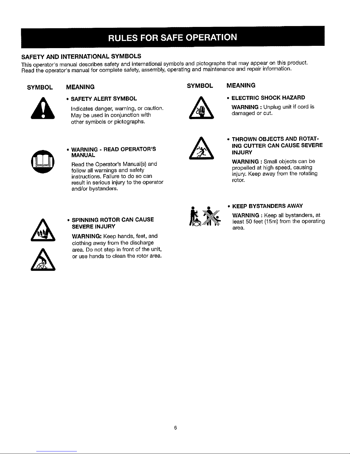
SAFETY AND INTERNATIONAL SYMBOLS
This operator's manual describes safety and international symbols and pictographs that may appear on this product,
Read the operator's manual for complete safety, assembly, operating and maintenance and repair information.
SYMBOL MEANING SYMBOL
* SAFETY ALERT SYMBOL
Indicates danger, warning, or caution.
May be used in coniunction with
other symbols or pictographs.
MEANING
• ELECTRIC SHOCK HAZARD
WARNING :Unplug unit if cord is
damaged or cut.
• WARNING - READ OPERATOR'S
MANUAL
Read the Operator's Manual(s) and
follow all warnings and safety
instructions. Failure to do so can
result in serious injury to the operator
and/or bystanders.
A
,* THROWN OBJECTS AND ROTAT-
ING CUTTER CAN CAUSE SEVERE
INJURY
WARNING : Small objects can be
propelled at high speed, causing
injury. Keep away from the rotating
rotor.
• SPINNING ROTOR CAN CAUSE
SEVERE INJURY
WARNING: Keep hands, feet, and
clothing away from the discharge
area. Do not step in front of the unit,
or use hands to clean the rotor area.
• KEEP BYSTANDERS AWAY
WARNING : Keep all bystanders, at
least 50 feet (15m) from the operating
area.
Page 8
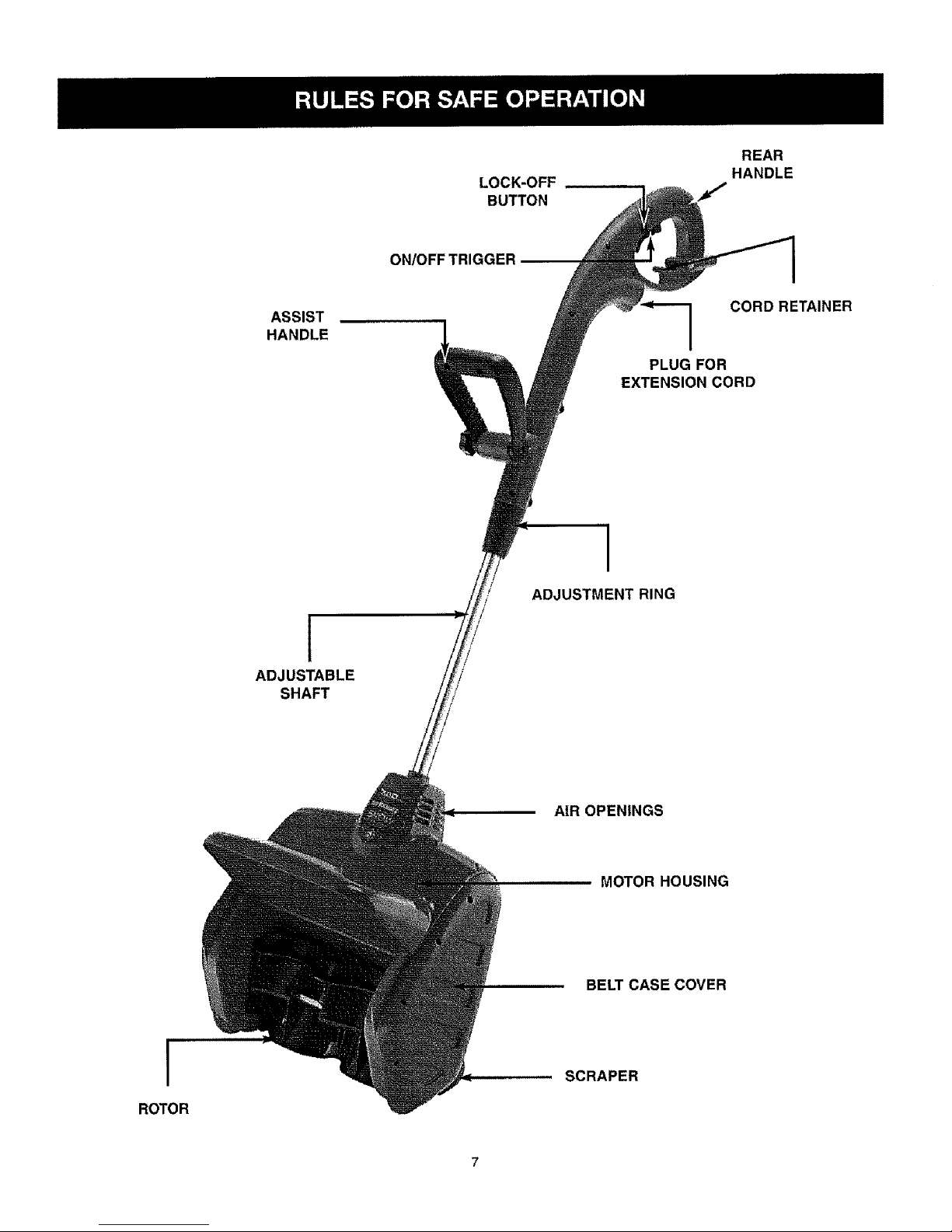
LOCK-OFF
BUTTON
REAR
HANDLE
ON/OFF TRIGGER
ASSIST
HANDLE
CORDRETAINER
PLUG FOR
EXTENSION CORD
ADJUSTABLE
SHAFT
/
/
/
/
ADJUSTMENT RING
AIR OPENINGS
MOTOR HOUSING
BELT CASE COVER
ROTOR
SCRAPER
Page 9
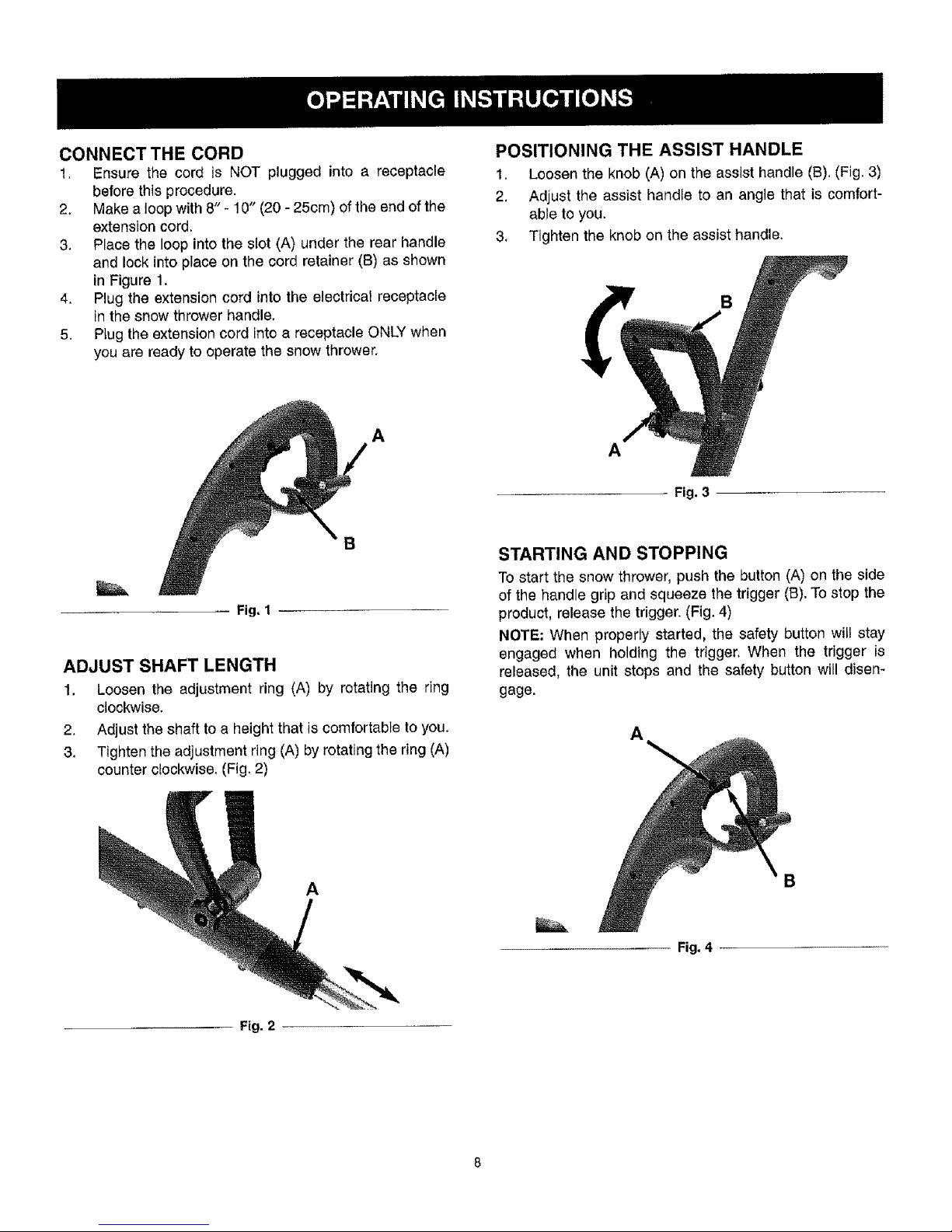
CONNECT THE CORD
1. Ensure the cord is NOT plugged into a receptacle
before this procedure.
2, Make a loop with 8" - 10" (20 - 25cm) of the end of the
extension cord.
3. Place the loop into the slot (A) under the rear handle
and lock into place on the cord retainer (B) as shown
in Figure 1.
4. Plug the extension cord into the electrical receptacle
in the snow thrower handle.
5, Plug the extension cord into a receptacle ONLY when
you are ready to operate the snow thrower.
A
B
ADJUST SHAFT LENGTH
1. Loosen the adjustment ring (A) by rotating the ring
clockwise.
2, Adjust the shaft to a height that is comfortable to you.
3. Tighten the adjustment ring (A) by rotating the ring (A)
counter clockwise. (Fig. 2)
POSITIONING THE ASSIST HANDLE
1, Loosen the knob (A) on the assist handle (B). (Fig. 3)
2, Adjust the assist handle to an angle that is comfort-
able to you.
3, Tighten the knob on the assist handle,
Fig. 3
STARTING AND STOPPING
To start the snow thrower, push the button (A) on the side
of the handle grip and squeeze the trigger (B). To stop the
product, release the trigger. (Fig. 4)
NOTE: When properly started, the safety button wiil stay
engaged when holding the trigger, When the trigger is
released, the unit stops and the safety button will disen-
gage.
A
A
Fig, 4
B
Fig. 2
Page 10
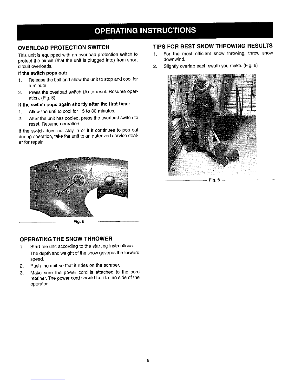
OVERLOAD PROTECTION SWITCH
This unit is equipped with an overload protection switch to
protect the circuit (that the unit is plugged into) from short
circuit overloads.
If the switch pops out.
1. Retease the bail and allow the unit to stop and cool for
a minute,
2. Press the overload switch (A) to reset, Resume oper-
ation. (Fig, 5)
If the switch pops again shortly after the first time:
1, Allow the unti to cool for 15 to 30 minutes,
2, After the unit has cooled, press the overload switch to
reset. Resume operation.
If the switch does not stay in or if it continues to pop out
during operation, take the unit to an autorized service deal-
er for repair,
Fig, 5
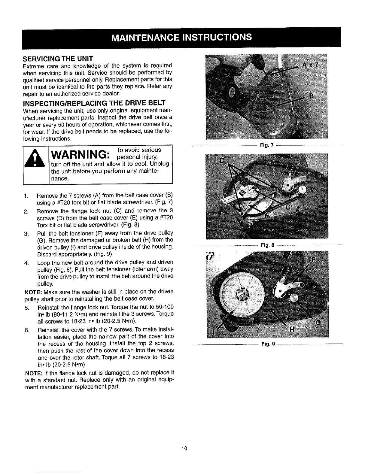
TIPS FOR BEST SNOW THROWING RESULTS
1. For the most efficient snow throwing, throw snow
downwind.
2, Slightly overlap each swath you make. (Fig. 6)
_i:i_ii_!:_iiiiiii_i!:_i__ _}_ _;_:,ii?_i_
OPERATING THE SNOW THROWER
1, Start the unit according to the starting instructions,
The depth and weight of the snow governs the forward
speed.
2. Push the unit so that it rides on the scraper.
3. Make sure the power cord is attached to the cord
retainer. The power cord should trail to the side of the
operator.
Fig. 6
Page 11
SERVICING THE UNIT
Extreme care and knowledge of the system is required
when servicing this unit. Service should be pedormed by
qualified service personnel only. Replacement parts for this
unit must be identical to the parts they replace, Refer any
repair to an authorized service dealer.
INSPECTING/REPLACING THE DRIVE BELT
When servicing the unit, use only original equipment man-
ufacturer replacement parts. Inspect the drive belt once a
year or every 50 hours of operation, whichever comes first,
for wear. If the drive belt needs to be replaced, use the foL-
lowing instructions.
I_ IAIADI_IIMt'_.- To avoid serious I
vv_"Lm z,zl,,a',z_,,,q, personal injury,
turn off the unit and allow it to cool. Unplug
the unit before you perform any mainte-
nance.
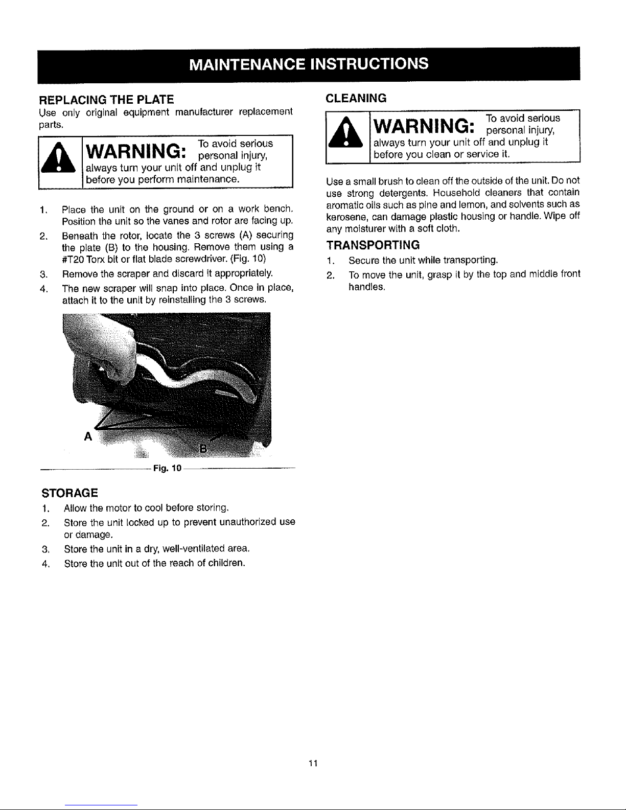
1, Remove the 7 screws (A) from the belt case cover (B)
using a #T20 torx bit or flat blade screwdriver. (Fig. 7)
2, Remove the flange lock nut (C) and remove the 3
screws (D) from the belt case cover (E) using a #T20
Torx hit or flat blade screwdriver. (Fig, 8)
3. Pull the belt tensioner (F) away from the drive pulley
(G). Remove the damaged or broken belt (H) from the
driven pulley (I) and drive pulley inside of the housing.
Discard appropriately. (Fig. 9)
4. Loop the new belt around the drive pulley and driven
pulley (Fig. 8). Pull the belt tensioner (idler arm) away
from the drive pulley to install the belt around the drive
pulley.
NOTE; Make sure the washer is still in pface on the driven
pulley shaft prior to reinstalling the belt case cover.
5. Reinstall the flange lock nut. Torque the nut to 50-100
in° lb (90-11,2 N*m) and reinstall the 3 screws. Torque
all screws to 18-23 in, Ib (20-2.5 Nom).
6. Reinstall the cover with the 7 screws. To make instal-
lation easier, place the narrow part of the cover into
the recess of the housing. Install the top 2 screws,
then push the rest of the cover down into the recess
and over the rotor shaft. Toque all 7 screws to 18-23
in, Ib (20-2.5 N°m)
NOTE: If the flange Iock nut is damaged, do not replace it
with a standard nut. Replace only with an original equip-
ment manufacturer replacement part.
Fig. 7
Fig. 8
10
Fig. 9
Page 12
REPLACING THE PLATE
Use only original equipment manufacturer replacement
parts,
WAl_lklllkl#__ " To avoid serious I
rtmlmm1%,_, personal injury,
J
always turn your unit off and unplug it
before you perform maintenance.
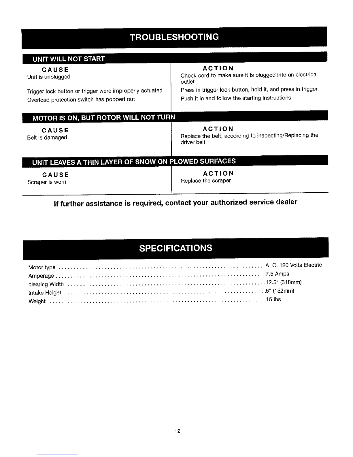
1, Place the unit on the ground or on a work bench,
Position the unit so the vanes and rotor are facing up,
2. Beneath the rotor, locate the 3 screws (A) securing
the plate (B) to the housing. Remove them using a
#T20 Torx bit or flat blade screwdriver. (Fig, 10)
3. Remove the scraper and discard ft approprlatety.
4. The new scraper will snap into place. Once in place,
attach it to the unit by reinstalling the 3 screws,
Fig. 10
CLEANING
WARNING: Toavo .ser o.s
personal injury,
always turn your unit off and unplug it
before you clean or service it.
Use a small brush to clean off the outside of the unit, Do not
use strong detergents, Household cleaners that contain
aromatic oils such as pine and lemon, and solvents such as
kerosene, can damage plastic housing or handle. Wipe off
any moisturer with a soft cloth.
TRANSPORTING
1. Secure the unit while transporting.
2. To move the unit, grasp it by the top and middle front
handles.
A
STORAGE
1, Allow the motor to cool before storing,
2. Store the unit locked up to prevent unauthorized use
or damage.
3. Store the unit in a dry, well-ventilated area,
4. Store the unit out of the reach of children.
11
Page 13
CAUSE
Unit is unplugged
Trigger lock button or trigger were improperly actuated
Overload protection switch has popped out
ACTION
Check cord to make sure it is plugged into an electrical
outlet
Press in trigger lock button, hold it, and press in trigger
Push it in and follow the starting instructions
CAUSE
Belt is damaged
ACTION
Replace the belt, according to inspecting/Replacing the
driver belt
CAUSE
Scraper is worn
ACTION
Replace the scraper
If further assistance is required, contact your authorized service dealer
Motor type .................................................................... A. C, 120 Volts Electric
Amperage ..................................................................... 7.5 Amps
clearing Width ................................................................. 12.5" (318mm)
Intake Height .................................................................. 6" (152mm)
Weight ....................................................................... 15 tbs
12
Page 14
io
ii
12
1
/
54
45
46
39
50
36
35
1
2
:3
4
5
6
7
8
9
10
I"L
12
13
14
15
t6
t7
t8
19
2O
21
22
23
24
25
26
27
2B
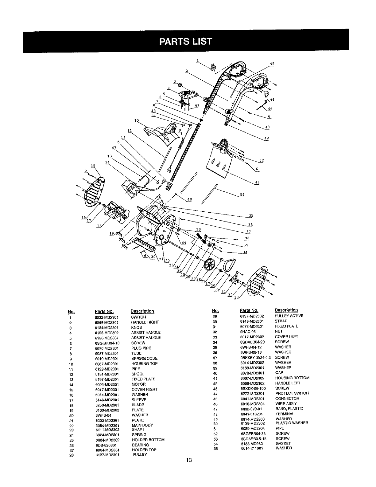
6022-MD2301
6068-M02301
6134 -MD2301
6198-MD23{}2
6186-MD2301
6SGEBB04-18
6070-MD2301
6037-MD2301
6010-MD2301
6067-MD230l
6129.MD230t
6131-MD2301
6187-MD2_301
6099-MD230t
6017-MD230t
6014-MD2301
614B.MD2301
6250.MD230t
6100,MD25O2
6WFB-04
6200-MD2301
6084-MD2301
6!11-MD2302
6024-MO2301
6004.MD2302
6DB-620301
6004-MD2301
6137-M D2301
SWITCH
HANDLE RtGHT
KNOB
ASSIST HANDLE
ASSIST HANDLE
SCREW
PLUG PiPE
TUBE
SPRING CODE
HOUSING TOP
PiPE
SPOOL
FIXED PLATE
MOTOR
COVER RIGHT
WASHER
SLEEVE
BLADE
PLATE
WASRER
PLATE
MAIN BODY
SHAFT
SPRING
HOLDER BOTI'OM
BEARING
HOLDER TOP
PULLEY
13
NO,
29
30
31
32
33
34
35
36
37
38
39
40
4t
42
43
44
45
46
47
48
49
5O
51
52
53
54
55
Pa_sNo.
6137-MD2302
6t49-MD2301
6072-MD2301
9NAC-OB
6017-MD2302
6SDABB04-20
6WFB-04*12
9WFB-08-13
PULLEY ACTIVE
STRAP
FIXED PLATE
NUT
COVERLEFT
SCREW
WASHER
WASHER
9SKKBYI 0/24-0,5 SCREW
60_ 4=MD2302
6189-MD2301
6078-MD230t
6067-MD2302
6068-MD2302
6SXDZ.06-15O
6272-MD23Ot
6041-MD230t
60t0-MD2304
6032-070-01
6041.61020t
60t4.MO22O3
6139-MD2302
6059-MD2304
6SGEBB04-35
6SDASB3,5*I 8
6183.MC2301
6014-211901
WASHER
WASHER
CAP
HOUSING BOTTOM
HANDLELEFT
SCREW
PROTECTSWITCH
CONNECTOR
WIREASS'Y
BAND, PLASTIC
TERMINAL
WASHER
PLASTIC WASHER
PIPE
SCREW
SCREW
GASKET
WASHER
Page 15

t4
Page 16

MANUFACTURER'S LIMITED WARRANTY FOR:
YARD
The limited warranty set forth below is given by MTD
LLC ("MTD") with respect to new merchandise purchased and
used in the United States and Canada, its possessions and
territories.
MTD warrants this product against defects in material and
workmanship for a period of two (2) years commencing on the
date of original purchase and will, at its option, repair or
replace, free of charge, any part found to be defective in
material or workmanship. This Iimited warranty shall only apply
if this product has been operated and maintained in
accordance with the Operator's Manual furnished with the
product, and has not been subject to misuse, abuse,
commercial use, neglect, accident, improper mainlenance,
alteration, vandalism, theft, fire, water or damage because of
other peril or natural disaster. Damage resulting from the
installation or use of any accessory or attachment not
approved by MTD for use with the product(s) covered by this
manual will void your warranty as to any resulting damage,
This warranty is limited to ninety (90) days from the date of
original retail purchase for any MTD product that is used for
rental or commercial purposes, or any other income-producing
purpose will void the warranty.
HOW TO OBTAIN SERVICE: Warranty service is available,
WITH PROOF OF PURCHASE THROUGH YOUR LOCAL
AUTHORIZED SERVICE DEALER. To locate the dealer in
your area, please check for a listing in the Yellow Pages or
contact the Customer Service Department of MTD LLC by
calling 1-866-747-9816 or writing to P.O. Box 361131,
Cleveland OH 44136-0019 or if in Canada call 1-800-668-
1238. No product returned directly to the factory will be
accepted unless prior written permission has been extended
by the Customer Service Department of MTD LLC.
This limited warranty does not provide coverage in the
following cases:
A. Drive Belt.
g.
MTD does not extend any warranty for products sold or
exported outside of the United States of America and
Canada, its possessions and territories, except those sold
through MTD's authorized channels of export distribution.
MTD reserves the right to change or improve the design of any
MTD Product without assuming any obligation to modify any
product previously manufactured.
No implied warranty, including any implied warranty of
merchantability or fitness for a particular purpose, applies
after the applicable period of express written warranty
above as to the parts as identified. NO other express
warranty or guaranty, whether written or oral, except as
mentioned above, given by any person or entity, including
a dealer or retailer, with respect to any product shall bind
MTD. During the period of the Warranty, the exclusive
remedy is repair or replacement of the product as set
forth above. (Some states do not allow limitations on how
long an impfied warranty lasts, so the above limitation may not
apply to you.)
The provisions as set forth in this Warranty provide the
sole and exclusive remedy arising from the sales. MTD
shall not be liable for incidental or consequential loss or
damages including, without limitation, expenses incurred
for substitute or replacement lawn care services, for
transportation or for related expenses, or for rental
expenses to temporarily replace a warranted product,
(Some states do not allow limitations on how long an implied
warranty lasts, so the above limitation may not apply to you.)
in no event shall recovery of any kind be greater than the
amount of the purchase price of the product sold. Alteration of
the safety features of the product shall void this Warranty. You
assume the risk and liability for loss, damage, or injury to you
and your property and/or to others and their property arising
out of the use or misuse or inability to use the product.
This limited warranty shall not extend to anyone other than the
original purchaser, original lessee or the person for whom it
was purchased as a gift.
How State Law Relates to this Warranty; This warranty
gives you specific legal rights, and you may also have other
rights which vary from state to state.
To locate your nearest service dealer dial 1-866-747-9816 in
the United States or 1-800-668-1238 in Canada.
MTD LLC
P.O. Box 361131
Cleveland, OH 44136-0019
!5
Page 17

YARD
Manuel de Utilisation
D_neigeuse
Electrique
31A-020-900
IMPORTANT: LISEZ LES RI_GLES ET
CONSIGNES DE SI_CURITI_ SOIGNEUSEMENT
P/N 6096-MD2301 (2)
FABRIQU# ik CHLNA
Page 18

Consignes de s6curit6
Instructions pour montage
Instructions de mantenimiento
D6pannage
Caract_ristiques
Pages 18-23
Pages 24-25
Pages 26-27
Page 28
Page 28
Liste des pi_ces Page 29
Notes Page 30
Garantie Iimit6e du fabricant pour Page 31
17
Page 19

Les Symbotes de securite attirent votre attention sur
des dangers potentiels. Ces symboles et leurs details
explicatifs meritent que vous les lisiez et compreniez
bien. Les avertissements de securit6 ne peuvent 6viter
les dangers de par eux-m_mes. Les consignes ou
mises en garde qu'ils donnent ne remplacent pas des
mesures preventives appropriees contre les accidents.
SYMBOLE SIGNIFICATION
f f
ALERTE DE SECURITE"
indique un danger, un avertissement ou une
mise en garde. Soyez vigilant afin d'eviter toute
blessure grave. Ce symbole peut 6tre combine
&d'autres symboles ou pictogrammes.
NOTE: Advises you of informationor instructions vital to 1[_'
the operation or maintenance of the equipment.
Read the Operator's Manual(s) and follow all warnings
and safety instructions.
Failure to do so can result in serious injury to the
operator and/or bystanders.
FOR QUESTIONS, CALL 1-800-668-1238
SYMBOLE SIGNIFICATION ....
DANGER: le non-respect d'un
avertissement peut
causer dommages materiels ou blessures
graves pour tous. Respectez les consignes
de securite afin de reduire tes risques
d'incendie, d'etectrocution et de blessures.
AVERTISSEMENT: le
non-respect d'un avertissement peut causer
dommages materiels ou blessures graves
pour tous. Respectez les consignes de
securit6 afin de reduire les risques d'incendie,
d'electrocution et de blessures.
MISE EN GARDE: lenon-
respect d'un avertissement peut causer
dommages materiels ou bfessures graves
pour tous. Respectez toujours les consignes
de securite afin de reduire les risques
d'incendie, d'electrocution et de blessures.
. IMPORTANTES CONSIGNES DE SI CURITI:!: •
LISEZ TOUTES LES INSTRUCTIONS
AVANT UTILISATION
AVERTISSEMENT :
Lorsque vous utilisez I'appareil, veuillez tire
les instructions quant aux regles de secu-
rite avant utilisation afin d'assurer la secu-
rite de I'utilisation et de son entourage.
Veuitlez conserver ces instructions pour une
utilisation ulterieure.
* Lisez les instructions avec attention. Familiarisez-vous
avec les commandes et la bonne utilisation de I'ap-
pareil.
• N'utilisez pas cet appareil si vous ¢tes fatigue, ou sous
I'influence d'alcool, de drogues et autres m6dicaments.
• Les enfants ne doivent pas utiliser I'appareil. Les ado-
lescents doivent etre accompagnes et guides par un
adulte.
• Toutes ies protections et pieces de securite doivent
etre installees oorrectement avant d'utiliser I'appareil.
Inspectez I'appareil avant utilisation. Remplacez les
pieces endommagees. Assurez-vous que toutes les fix-
ations sont en place. Remplacez les pieces fissurees,
ebrechees ou endommagees de quelque fa?on que ce
soit. N'utilisez pas l'appareil avec des pi¢ces desser-
tees ou endommag6es.
lnspectez minutieusement la zone avant de com-
mencer & utiliser I'appareil. Enlevez tousles debris et
les objets durs ou pointus tels que le verre, les fils, etc.
Eloignez les enfants, l'entourage et les animaux
domestiques de la zone. Au minimum, tenez les
enfants, votre entourage et les animaux domestiques
hors d'un rayon de 50 pieds (15m.) ; il reste toujours un
risque de projection pour votre entourage. Si on vous
approche, arretez immediatement I'appareil.
18
Page 20

LIRE ET CONSERVER CES
INSTRUCTIONS
Lorsqu'un appareil _lectrique est utilis_, des pr6cautions
_l_mentaires doivent toujours _tre prises pour assurer une
s_curit_ maximum et une performance optimale. Lire cette
Notice avant d'assembler et d'utiliser cet appareil. Ne pas
se conformer aux instructions peut causer des secousses
61ectriques, des b_lures, un incendie ou des btessures
corporelles.
AVERTISSEMENT
POUR REDUIRE LES RISQUES DE
BROLURES, D'INCENDIE, DE SECOUSSES
I_LECTRIQUES OU DE BLESSURES :
1, RESPECTER TOUTES LES MESURES DE
S_CURITI_ figurant dana cette Notice avant et durant
l'utilisation du coupe-herbe.
2. POUR REDUIRE LES RISQUES DE SECOUSSES
_LECTRIQUES, cet _quipement est muni d'une fiche
polaris_e (une broche est plus large que I'autre).
Cette fiche ne peut _tre branch_e que dans un sens
et que clans une prise de courant polaris6e. Si la fiche
ne peut pas 6tre enfonc_e & fond dans la prise de
courant, inverser le sens de la fiche. Ne jamais modi-
fier la fiche de t'appareil.
3, INSPECTER L'APPAREIL /_. LA RECHERCHE DE
DOMMAGES qu'auraient pu subir te carter, le cordon
_lectrique ou _ la fiche. Toutes tes fixations doivent
_tre bien serr6es. Ne pas utiNser !'appareil si la
g&chette ne permet pas de I'arreter ad_quatement.
Ne jamais utiliserI'appareil si le cordon _lectrique ou
la fiche est endommag_, si le moteur ou le coupe-
herbe lul-meme ne fonctionne pas correctement ou
s'il est tomb_, s'il a _t6 endommag6, laiss6 & I'ex-
t#rieur ou plong6 clans I'eau. Ne pas utillser I'appareit
si les trous de ventilation sont bouch_s. Toujours
enlever les d_bris qui risqueraient de limiter la circula-
tion de I'air par les trous de ventilation. Remplacer les
pi#ces endommag_es qui sont 6br6ch_es, cass_es
ou qui ont _t_ endommag_es d'une maniere ou d'une
autre et qui risqueraient d'etre projet_es et causer de
graves blessures. Garden le couteau de coupeur
aigu.
4. r_ DOUBLE ISOLATION pour prot_ger I'utilisateur
des risques de secousses 61ectriques. La double
isolation consiste en deux <<couches>>d'isolant #lec-
trique. Les appareils construits avec ce type d'isola-
tion ne sent pas con£us pour #tre mis & la terre. Par
consequent, le cordon prolongateur utilis6 avec le
coupe-herbe peut 6tre branch_ dans n'imperte quetle
prise de courant de 120 volts. Des mesures de s_cu-
rit6 _16mentaires doivent toujours 6tre prises
lorsqu'un appareil _tectrique est utilis_. La double iso-
lation constitue seutement une protection suppl_men-
taire en cas de d_faillance de l'isolant interne.
19
,
,
Quand le symbole double d'isolation (un carr6 dana
un carte) est utilis_ comme la seule marque pour
identifier une unit6 comme est double isol_, le sym-
bole sera d_fini dans le manuel d'instruction.
CORDON PROLONGATEUR - Ne brancher cet
appareil que dans un cordon prolongateur con?u pour
usage ext_rieur et d'un calibre ad_quat en fonction de
sa lengueur. Voir le tableau ci-dessous. Un cordon
prolongateur & 2 conducteurs ne poss6dant pas de
connexion & la terre peut _tre utilis6 6tant donn6 que
cet appareil est & double isolation. Si I'on n'est pas st3r
du calibre du cordon prolongateur & utiliser, utiliser un
cordon prolongateur de calibre imm_diatement
sup_rieur. I1est ¬er que plus le num_ro du calibre
est petit plus le cordon prolongateur est gros.
TENSION
120
III._ll III[l] l_!-t I] ::1[I'#_l II_i1:1
LONGUEUFIDU
CORDON
25 pieds/ 7,5m
50 pieds/ 15m
100 pieds/ 30m
iI :I _1=1111ll=_llI_Ih'_llj_=l
CALIBRE DE FIL
REQUIS
18 A.W,G2
16 A.W,G.*
16 A,W,G.*
*American Wire Gauge (CALIBRE AMERtCAIN)
Tableau I
(1). Un cordon prolongateur de diametre appropri6 dolt
etre utilis6 pour _viter les pertes de puissance et la
surchauffe de I'appareil.
(2). Le cordon prolongateur dolt 6tre sp6cialement con£u
pour usage ext_rieur et porter la mention <<SJ,> ou
<<SJT>>et le suffixe ,<WA>>.Au Canada, le cordon pro-
Iongateur doit porter la mention <<SFTW,>.
(3). S'assurer que le cordon prolongateur ne comporte
pas de ills d_nud_s ni desserr_s et que I'isolant n'est
pas endommag_. En cas de dommages, remplacer le
cordon prolongateur avant d'utiNser I'appareil.
NE PAS MALTRAITER LE CORDON - Ne jamais
transporter I'appareil par le cordon electrique ni tirer
sur le cordon _lectrique pour d_brancher !'appareih Le
cordon _lectrique dolt toujours 6tre tenu & 1'6cart de
i'ep6rateur et des obstacles. Ne pas exposer le cordon
_lectrique & des surfaces chaudes, de I'huNe ou de
I'eau. Ne pas tirer le cordon 61ectrique autour d'angles
vifs, de coins et veiller & ne pas le coincer dans une
porte en la fermant.
7, t_ AUCUNE PIECE INTERNE N'EST RI_PARABLE
PAR UUTILISATEUR - Cet appareil a double
isolation ne comporte aucune piece interne reparable
par I'utilisateur. Ne pas essayer de le reparer soi-
m6me. Pour tout renseignement concernant I'entre-
tien, s'adresser A un Centre de r_paration Yard
Machines dont le numero figure sur la couverture
arri_re de cette Notice d'utilisation.
Page 21

8. RISQUE DE BLESSURE A UCEIL - Portez toujours
des lunettes ou autres protections pour les yeux
]orsque vous utitisez votre deneigeuse. Tenez tou-
jours votre entourage _ une distance de s_curite.
9. HABILLEZ-VOUS CORRECTEMENT - Portez tou-
jours des pantalons longs, des chaussures et des
gants. Ne portez pas de vetements amples, de bijoux
; Portez des bottes en caoutchouc Iorsque vous
utillsez le deneigeuse.
10, LAISSEZ LA PLACE DEGAGEE - Tenez tout le
monde, surtout les enfants et les animaux domes-
tiques, & I'_cart de la zone d'utitisation, & 50 pieds
(15m). Eteignez immediatement I'appareil si on vous
approche. Ne laissez jamais un enfant utiliser Pap-
pareil comme un iouet ou le faire fonetionner sans
surveiNance.
11. N'utilisez pas sur une surface de graviers & moths
que la deneigeuse ne soit reglee en consequence el
conformement au mode d'emploi.
12. TENEZ LES ENFANTS A L'ECART - Tousles visi-
teurs doivent _.tretenus _.une distance de securit6 de
la zone de travail.
13, Portez des bottes en caoutchouc Iorsque vous
utilisez le deneigeuse.
14. Les consignes d'attention concernant I'utilisation de
v_tements et chaussures appropri_s pendant I'utili-
sation visent & reduire le risque de blessures qui
pourrait survenir en raison de debris volants.
"_5. L'utilisation de la deneigeuse en position manuelle
n'est pas s0re, saul si cela est fait en accord avec les
instructions particulieres fournies dens te mode
d'emploi.
16. AVERTISSEMENT - Cette deneigeuse dolt _tre retiee
la masse Iorsqu_etleest en fonctionnement afin de
proteger I'operateur de I'electrocution. Pour eviter les
electrocutions, n'utilisez que des prolongateurs
adaptes & un environnement ext_rieur.
17. PROLONGATEUR - Eviter que le cordon de la
deneigeuse se d_branche du prolongateur pendant
I'utilisation.
18. EMITER LE DEMARRAGE ACCIDENTEL - Ne pas
transporter la deneigeuse branchee avec le doigt sur
I'interrupteur. Assurez-vous que l'interrupteur est sur
Arret lots du branchement.
19. Sl le cordon est endommage d'une quelconque
re?on, enlevez te prolongateur de la prise secteur.
20. NE TIREZ PAS SUR LE CORDON - Ne transportez
jamais la deneigeuse par le cordon et ne tirez pas sur
le cordon pour le debrancher du secteur. Tenez le
cordon & I'ecart de la chaleur, de I'huile, et de arretes
tranchantes.
21. Tenez les mains 61oign_esdes parties mobiles,
22. Tenez les protections en place et en 6tat de marche.
23, NE FORCEZ PAS LA DENEIGEUSE - Elle fonction-
nera mieux et de fa?on plus sore & la vitesse pour
laquelle elle a et_ con?ue.
24. N'ALLEZ PAS HeRS DE PORTEE - Gardez un ben
appui et un ben equilibre & tout moment,
25. Si la deneigeuse percute un corps etranger, suivez tes
etepes suivantes:
i) Arr_tez fa deneigeuse.
ii) lnspectez les deg_ts.
iii) Reparez tout deg&t avant de redemarrer at d'utilis-
er la deneigeuse.
26, DEBRANCHEZ LA DENEIGEUSE - Debranchez la
deneigeuse de I'alimentation 61ectrique Iorsqu'elle
n'est pas utilisee, avant l'entretien, Iors du remptace-
ment d'accessoires, et autre.
27. STOCKEZ LES DENEIGEUSES EN INTERIEUR -
Lorsqu'elles ne sent pas utilisees, les deneigeuses
doivent 6tre stockees en interieur,au sec, et dens un
endroit verrouille - hers de portee des enfants.
28. MAINTENEZ LES DENEIGEUSES AVEC SOIN -
Suivez les instructions pour la lubrification et le rem-
placement d'accessoires.
29. N'utilisez aucun autre accessoire ou pf_ce rapportee
qui pourrait augmenter le risque de blessure.
PENDANT L'UTILISATION
1. Marchez, ne courrez jamais.
2, Assurez-vous que la deneigeuse n'est pas en contact
avec quoi que ce soit avant de demarrer I'appareil.
3. Restez & distance de I'ouverture de decharge & tout
moment. Conservez ]e visage, les mains et les pieds
& I'ecart des pieces mobiles ou rotatives cachees.
4. Soyez attentlf Iorsque vous utilisez la deneigeuse, et
restez vigilent quant aux trous dens {e terrain et
autres dangers ou traffics caches.
5. N'utilisez pas sur une surface de sable ou de
graviers. Faites extremement attention Iorsque vous
traversez des allees, des chemins ou des routes de
sable ou de graviers.
6. N'enlevez jamais la neige des pentes raides.
7. N'essayez jamais d'utiliser la deneigeuse sur un toit
ou une autre surface inctlne, raide ou gllssante.
8. N'utilisez jamais la deneigeuse sans plaques de pro-
tection approprieesou autre dispositifs de protection
de securit_ en place.
9. N'utilisez jamais la deneigeuse pres d'enceintes en
verre, d'automebiles, de camions, de fen_tres, de
puits, d'&-pics, etc sans un reglage correct de I'angle
de decharge de la neige. Tenez enfants et animaux
domestiques _ I'_cart.
10. Ne forcez pas et ne surchargez pas la d_neigeuse. La
deneigeuse fonctionnera mieux et de fagon plus s0re
_.la vitesse pour laquelle elfe a et6 con?ue.
20
Page 22

11. Ne dechargez jamais directement vers des gens et ne
laissez personne rester devant I'appareil en fonctlon-
nement.
12. Portez des lunettes ou un masque de securite, mar-
que conforme aux normes ANSi Z87.1, et des protec-
tions auditives torsque t'appareil est en marche.
13. N'utilisez l'unite qu'& la lumi_re du jour ou avec une
bonne lumi_re artificielle.
14. Evitez tout demarrage accidentel. Restez en position
de d_marrage & chaque fois que vous demarrez Pap-
parei!. L'operateur et l'appareil doivent 6tre en posi-
tion stable lots du demarrage.
15. UtiNsez le bon outil. N'utilisez un outil que pour ce &
quoi il sert.
16. N'allez pas hors de portee. Gardez un bon appui et
un bon equilibre #.tout moment.
17, Teneztoujours I'appareil & deux mains quand il est en
marche. Tenez fermement tes poignees ou les grips.
18. Tenez les mains, le visage et les pieds & bonne dis-
tance de toutes les pieces mobiles. Ne touchez pas
le rotor et n'essayez pas de I'arreter pendant qu'it
tourne.
19. Si le rotor ne teurne pas librement & cause de glace
congelee, laissez bien fondre avant de tenter d'utilis-
er I'appareil sous tension.
20. Gardez le rotor Iibre de tout debris,
21. Ne tentez jamais de nettoyer le rotor quand le moteur
tourne. Eteignez le moteur d'abord, et debranchez le
cordon d'alimentation.
22. Conservez vos vetements et les parties du corps &
distance du rotor.
23. Arr6tez toujours le moteur Iorsque vous differez le
deblayage de neige ou Iorsque vous vous deplacez
d'un endrolt _ un autre.
24. Desengagez I'alimentation du rotor Iorsque la
deneigeuse est transportee ou n'est pas utilisee.
25. Apr_s avoir percut6 un corps _tranger, eteignez I'ap-
pareif et inspectez fes deg&ts sur la deneigeuse.
Debranchez I'appareil. Reparez tout deg&t avant de
redemarrer et d'utiliser !'appareil.
26. Si I'appareil commence & vibrer anormatement,
arretez le et verifiez immediatement quelle en est la
cause. Les vibrations sont en g_neral I'annonce de
problemes.
27. Arretez le moteur et debranchez I'appareil d_s que
vous quittez la position d'utilisation, avant de deblay-
er le rotor et de decharger les palettes, et Iorsque
vous faites des reparations, des r_glages ou des
inspections.
28. N'utilisez que des pieces de rechange et des acces-
soires d'origine pour cet appareN. Ils sont disponibles
aupres de votre reprL,sentant de maintenance agree.
L'utilisation de pl_ce ou d'accessoires non agrees
21
peut causer de serieuses blessures & I'utilisateur ou
endommager I'appareil, et annuler votre garantie.
29. N'utilisez pas I'appareil en position manuelle. Ne
ramassez pas I'appareil lorsqu'il est sous tension et
en marche. L'appareil est con?u pour voyager le long
du sol.
AUTRES AVERTISSEMENT DE SECURITE
1. Assurez-vous d'attacher t'appareil pour le transport.
2. Stockez I'appareil dans une zone seche, verrouillee
ou en hauteur pour _viter une utilisation non autorisee
ou des deg&ts, et hors de portee des enfants.
3. Ne mouillez jamais I'appareil avec de I'eau ou un
autre liquide. Tenez les poignees s6ches, propres et
Nbres de debris. Nettoyez awes chaque utilisation.
4. Si fes etiquettes de I'appareil s'effacent ou devien-
nent illisibles, contactez votre representant de main-
tenance agree.
5. Conservez ces instructions, Referez-vous y souvent
et utilisez les pour informer les autres utilisateurs. Si
vous pr6tez cet appareil, pretez egalement ces
instructions.
6. Maintenez la d_neigeuse avec soin. Suivez ces
EXPLICATION DES NOTA, AVERTISSEMENTS
ET SYMBOLES DE LA GARANTIE
1. Un NOTA est destin_ _ fournir des informations com-
plementaires, & 6claircir un point particufier ou & expli-
quer plus en d_tail une etape.
2. Un AVERTISSEMENT identifie une procedure qui
risque de causer de graves blessures corporelles ou
de graves dommages & I'appareil et/ou les deux si elle
n'est pas respectee ou si elle est mal effectuee.
3. Le _) (SYMBOLE DE GARANTIE) indique que si les
procedures ou instructions n'ont pas 6t_ respectees,
les dommages causes annuleront la garantle et que
les reparations seront & la charge du propri_taire.
Pour des services autres que ceux d'entretien &
effectuer par l'utilisateur, s'adresser & un Centre de
r_paration agr_6 Yard Machines. La garantie du fabri-
cant sera nulle et non avenue si des dommages ou
des conditions causes par de mauvaises pratiques
d'entretten rendent le produit inutilisable.
4. POUR TOUT ENTRETIEN OU SERVICE AU TITRE
DE LA GARANTIE prenez contact avec le Centre de
maintenance agr_6 MTD le plus proche en appelant
le num_rogrtuit 800# mentionne sur le capot arri#re.
CONSERVER CES
INSTRUCTIONS
Page 23

SYMBOLES DE SI=CURITI _ ET INTERNATIONAUX
Ce manuel de ['utilisateurd_crit les symboles et pictogrammes de s_curit6 et intemationaux pouvant appara_re sur ce
produit. Consultez le manuel de l'utilisateur pour les informatlonsconcernant la s6curit6, le montage, le fonctionnement,
I'entretien et les r6parations.
SYMBOLE SIGNIFICATION
• SYMBOLE ALERTE DE I_
SteCURITI_
Indique un danger, un avertissement
ou une mise en garde, Ce symbole
peut 6tre combin6 &d'autres symbol-
es ou pictogrammes.
" AVERTISSEMENT - LISEZ LE
MODE DiEMPLOI
Llsez le(s) mode(s) d'ernploi et suivez
tous les avertissements et conslgnes
de s_curit& Ne pas le faire peut vous
exposer & des blessures graves pour
I'utilisateur ou pour son entourage.
LE ROTOR EN ROTATION PEUT
CAUSER DE SEVERES
BLESSURES
AVERTISSEMENT: Tenez les mains,
les pieds, et les v6tements & l'6cart
de la zone de decharge. Ne marchez
pas en face de I'appareil, et n'uttlisez
pas les mains pour nettoyer la zone
du rotor.
A
• tl
SYMBOLE SIGNIFICATION
• RISQUE D'ELECTROCUTION
AVERTISSEMENT : D_branchez cet
appareil si le cordon est endommag6
ou coup&
LES OBJETS PROJETS ET LES
LAMES EN ROTATION PEUVENT
CAUSER DE SEVERES
BLESSURES
AVERTISSEMENT : Les petits objets
peuvent 6tre projet_s 9.haute vitesse,
causant des blessures. Restez & 1'6-
cart du rotor en marche.
, TENEZ VOTRE ENTOURAGE A L'E-
CART
AVERTISSEMENT : Teneztout votre
entourage & au moins 50 pieds (15m)
de la zone d'utiNsation,
22
Page 24

BOUTON DE VERROUILLAGE
POIGNI_E
ARRIERE
f
GACHETTE MARCHE/ARRI_T
POIGNI'--'E
D'AIDE
SUPPORT DE
CORDON
PRISE POUR
PROLONGATEUR
I
/
ARBRE RI_GLABLE /
!
/
/
/
I
BAGUE DE RI_GLAGE
OUVERTURES
D'AIR
LOGEMENT
MOTEUR
CAPOT COURROIE
ROTOR
GRATEUR
23
Page 25

BRANCHEZ LE CORDON
1. Assurez-vous que le cordon N'est PAS branch_ sur le
secteur avant d'effectuer cette procedure,
2. Faites une boucle avec 8 " - 10 " (20 - 25cm) de l'ex-
tr6mit_ du prolongateur.
3. Placez Laboucle dans la fente (A) sous la poign6e
arri_re et verrouillez en place sur lesupport de cordon
(B) comme indiqu_ & la figure 1.
4. Branchez la ratlonge d'alimentation sur la prise _lec-
trique situ6e sur le manche de la d(_neigeuse.
5. Branchez la rallonge sur le secteur SEULEMENT
Iorsque vcus 6tes prSt & utiliser la d6neigeuse.
A
B
REGLEZ LA LONGUEUR DE L'ARBRE
1. Desserrez la bague de r_glage (A) en faisant tourner
la bague darts le sens des aiguilles d'une montre.
2, R_glez I'arbre jusqu'& une hauteur qui vous est con-
fortable
3. Serrez la bague de r6glage (A) en faisant tourner la
bague dans le sens contraire des a[gullles d'une
montre. (FLg.2)
POSITIONNEMENT DE LA POIGNEE D'AS-
SISTANCE
1, Desserrez le bouton (A) sur la poign_e d'assistance
(B). (Fig. 3)
2. R_glez la poign_e d'assistance & un angle qui vous
est confortable.
3, Serrez le bouton sur la poign6e d'assistance.
A
Fig. 3
DEMARRAGE ET ARRET
Pour d_marrer la d_neigeuse, enfoncez la bouton (A) sur le
cSt_ de la poign_e et enfoncez la g&chette (B). Pour arr6ter
le produit, rel&chez la g&chette, (Fig. 4)
REMARQUE: Une lois correctement d_marr_, la bouton de
s_curit_ reste engag6 Iorsque vous tenez la g&chette.
Lorsque la g&chette est rel&ch_e, I'appareil s'arr6te et le
bouton de s_cudt_ se d_sengage,
A
A
Fig, 4
B
Fig. 2
24
Page 26

INTERRUPTEUR DE PROTECTION CONTRE
LES SURCHARGES
L'appareil est 6quip6 d'une protection centre les sur-
charges pour prot6ger le circuit (sur tequel I'appareil est
branch6) contre les surcharges de courts-circuits.
Si f'interrupteur se soul6ve:
1. Lib6rez la s_curit_ et laissez I'appareil s'arr6ter et
refroidir une minute.
2. Appuyez sur I'interrupteur de surcharge (A) pour
r6initialiser. Continuer I'utilisation. (Fig. 5)
Si I'interrupteur se re-d6clenche peu de temps apr_s la
premiere fois:
1. Laissez l'appareil refroidir 15 _ 30 minutes,
2. Une fois que I'appareit est refroidi, appuyez sur I'in-
terrupteur de surcharge pour r6initialiser. Continuer
I'utilisation.
Si I'interrupteur ne reste pas enclench6 ou s'il continue de
sortir en fonctionnement, emmenez I'appareil chez un
repr6sentant de maintenance agr66 pour une r_parat[on.
Fig, 5
ASTUCES POUR UN MEILLEUR
DENEIGEAGE RESU LTATS
1. Pour t,Jnd6neigeage plus efficace, rel&chez la neige
dans fe sens du vent.
2. Recouvrez 16g6rement chaque passe que vous faites.
(Fig. 6)
Fig. 6
UTILISATION DE LA DENEIGEUSE
1. D6marrez l'apparei! selon les instructions de d6mar-
rage. La profondeur et le poids de la neige r6gissent
la vitesse d'avance,
2. Poussez I'appareil pour qu'il repose sur son grattoir,
3. Assurez°vous que le cordon d'alimentation est reli6 au
support de cordon. Le cordon d'alimentation dolt suiv-
re I'utilisateur sur ie c5t6.
25
Page 27

MAINTENANCE DE L'APPAREIL
Un soin et une connaissance du systeme extr6mes sont
requis pour la maintenance de cet appareil. L'entretien ne
doit _tre effectu6 que par du personnel de maintenance
quaIifi_. Les pi_ces de rechange pour cet appareil doivent
6tre identiques aux pieces qu'eltes remplacent. Renvoyez
toute r6paration & un repr6sentant de maintenance agr66.
INSPECTION/REMPLACEMENT DE LA COUR-
ROlE
Lorsque vous entretenez I'appareil, n'utilisez que des
pi_ces de rechange et des accessoires d'origine. Inspectez
la courroie d'entminement une fois par an ou toutes lee 50
heures de fonctionnement, en prenant en compte la pre-
miere des deux conditions rempiies. Si la courroie d'en-
trainement doit etre remplac_e, utilisez les instructions
suivantes.
AVERTISSEMENT: Pou,
6viter des btessures personnelles graves,
6teignez !'appareil et laissez le refroidir.
D6branchez I'appareil avant d'effectuer
toute maintenance.
1. Enlevez les 7 vis (A) du capot de la courroie (B) &
I'aide d'un tournevis & bout en 6toile #T20 ou b, bout
plat, (Fig, 7)
2. Enlevez l'_crou de verrouillage du panneau (O) et
enlevez les 3 vis (D) du capot de la courroie (E) &
I'aide d'un tournevis & bout en 6toile #T20 ou & bout
plat. (Fig. 8)
3. Tirez sur le tenstonneur de courroie (F) pour l'_loign-
er de la poulie d'entrafnement (G). Enlevez la courroie
endommag_e ou cass_e (H) de la poulie entrafn6e (i)
et de la poulie d'entrafnement du logement.
D_barrassez-vous en de fagon appropri_e, (Fig, 9)
4, Enroulez la nouvelle courroie autour de la poulie
entrain6e et de la poulie d'entrafnement (Fig, 8).Tirez
sur le tensionneur de courroie (bras inerte) pour
I'_loigner de la poulie d'entraTnement et installer la
courroie autour de la poulie d'entrafnement, lez la
nouvelle courroie autour de la poulie entraTn6e et de
la poulie d'entraTnement (Fig. 8). Tirez sur le tension-
neur de courroie (bras inerte) pour I'_loigner de la
poulie d'entrainement et installer la courroie autour de
ta poulie d'entratnement.
REMARQUE: Assurez-vous que la rondelle est toujours en
place sur I'arbre de la poulie entrafn_e avant de r_installer
le capot de la courroie.
5. R6installez t'_crou de verrouillage de la paroi. Serrez
le boulon & 50-100 pouceo livre (90-11.2 Nom) et r_in-
stallez les 3 vis,Serrez toutes les vis & 18-23 pouceo
livre (20-2.5 Nora).
6. R6installez le capot aveo les 7 vis. Pour rendre I'instal-
lation plus facile, placez la pattie _troite du capot dans
le retrait du logement, InstaHez fes 2 vis du dessus,
puis enfoncez le reste du capot vers le bas dans le
retrait et au dessus de I'arbre du rotor. Serrez les 7 vis
18-23 peuceo !ivre (20-2,5 Nom)
REMARQUE-'Si l'_crou de verrouiilage de la paroi est
endommag6, ne le replacez pas par un 6crou standard.
N'utilisez que des pieces de rechange et des accessoires
d'origine.
26
Fig. 7
Fig. 8
Fig. 9
Page 28

REMPLACEMENT DE LA PLAQUE
N'utilisez que des pi_ces de rechange d'origine.
AVERTISSEMENT:
Pour 6viter des blessures personne!les
graves, _teignez toujours I'appareil et
d_branchez le event d'effectuer la mainte-
nance.
1, Placez l'appareil sur le sol eu sur un 6tabli.
Positiennez I'appareil de sorte que /e8 palettes et le
rotor seient orient6s vers le haut.
2. Sous le rotor, rep_rez les 3 vls (A) qui retient la plaque
(B) au Iogement. Enlevez les & I'aide d'un tournevis &
bout en _toile #T20 ou & bout plat. (Fig. 10)
3. Enlevez le grattoir et d_barrez-vous en de fagon
eppropri_e.
4. Le nouveau grattoir s'enclenche & sa place, Une lois
en place, attachez le & I'apparetl en r_installant les 3
vis.
Fig, 10
NETTOYAGE
AVERTISSEMENT: pour
_viter des btessures personnelles graves,
6teignez toujours I'appareil et d6branchez
le event d'effectuer ta maintenance ou le
nettoyage.
UtiNsez une petite brosse pour nettoyer I'ext6rieur de I'ap-
pareil, N'utilisez pas de d_tergents forts, Les nettoyants
m6nagers qui contiennent des huiles aromatiques teNes
que le pin et le citron, et les selvants teis que le k6ros6ne,
peuvent endemmager le boftier ou les poign6es en plas-
tique,
Essuyez toute trace de moisissure avec un chiffon doux.
TRANSPORT
1. Attachez I'appareil pour le transport.
2. Pour d_placer I'appareil, tenez le par les poign6es du
haut et du milieu & I'avant.
A
EMMAGASINAGE
1. Laissez le moteur refrotdlrevent le stockage.
2. Stockez l'appareil verrouill_ pour _viter une utilisation
non autoris6e ou des d_g&ts,
3. Stockez I'appareil dans une zone s_che bien ventil_e,
4. Stockez I'appareil hers de port6e des enfants,
27
Page 29

CAUSE
L'appareil est debranch_
Le bouton de verrouillage de la g&chette ou la g&chette,
a et6 maf actionne.
L'interrupteur de protection contre les surcharges est sorti
SOLUTION
Verifiez le cordon pour vous assurer qu'il esst branch8 sur
une prise secteur
Enfoncez le bouton de verrouillage de la g&chette, main-
tenez le, et appuyez sur la g&chette
Enfoncez ta et suivez les instructions de demarrage
CAUSE
La courroie est endommagee
SOLUTION
Remplacez la courroie, aprSs inspection / Remplacement
de la courroie
CAUSE
Le grattoir est us{_
SOLUTION
Remplacez te grattoir
S'il vous faut plus d'aide, contactez votre centre de maintenance agr_
Moteur type ................................................................. A, C. Electrfque 120 Volts
Amperage .................................................................. 7.5 A
d_gagement Largeur .......................................................... 12.5" (3t8mm)
Entree Hauteur .............................................................. 6" (152mm)
Poids ...................................................................... 15 Iivres
28
Page 30

1
45
15
6
10
11
/
43
42
5O
36
35
No _ _e_s_ematL_
I 6022-MD2301 lNTERRUPTEUR
2 60B8-MD2301 POIGNEE DROITE
3 6134-B23801 BOUTON
4 8196-MD2302 POIGNEE D'AIDE
5 6196=MD2301 POIGNEE D'AIDE
6 6SGEBB04-18 VIS
7 6070-B23B01 TUYAU BOUCHON
8 6037-MD2301 TUBE
9 60t0-MD2301 CODE RESSORT
10 6067-MD2301 DESSUS BOITEER
1t 6129-MD2301 TUYAU
12 6131 -MD2301 BOBINE
13 6187-MD2301 PLAQUE FIXE
14 6099-MD2301 MOTEUR
15 6017-MD2301 CAPOT DROIT
16 6014_MD2301 RONDELLE
17 6148-MD2301 MANCHON
t8 6250-MD2301 LAME
I9 6100-MD2302 pLAQUE
20 6WFB-O4 RONDELLE
21 6200-MD2301 PLAQUE
22 6064-MD2301 CORPS PRINCIPAL
23 6111 *MD230f ARBRE
24 6024-MD230t RESSORT
25 6004-MD2302 DESSOUS SUPPORT
26 6DB-620301 ROULEMENT
27 6004-M D2361 DESSUS SUPPORT
28 6137-MD2361 POULIE
29
N_N_..pi_ce
29 6137-MD2302 POULIE ACTIVE
30 6149-MD2301 BANDE
31 6072-MD230t PLAQUE FIXE
32 9NAC-08 ECROU
33 6017-MD2302 CAPOT GAUCHE
34 6SDABBO4-2O VlS
35 6WFB-O4-12 RONDELLE
36 9WFB-0843 RONDELLE
37 9SKKBYlOi24-O.5 VIS
38 6014-MO2302 RONDELLE
39 6189-MD230t RONDELLE
40 6078-MD2301 BOUCHON
41 6067-MD2302 DESSOUS BOITIER
42 6068-MD2802 PO1GNEE GAUCHE
43 6BXDZ-O6-1O0 VIS
44 6072-MD2302 tNTERRUPTEUR DE PROTECTION
45 6041-MD2301 CONNECTEUR
46 6610-MD2304 FIL
47 6032-070-01 IA BANDE, LE PALSTIQUE
48 6041-6t0201 TERMINAL
49 6014-MD2303 RONDELLE
50 6139-MD2302 RONDELLE EN PLASTIQUE
51 6059-MD2304 TUYAU
62 6SGEBB04-35 VIS
53 6SDAB B3.5-18 VIS
54 6183-MD2301 JOINT
55 6014-211901 RONDELLE
Page 31

30
Page 32

GARANTIE LIMITEE DU FABRICANT POUR:
YARD
La garantie limit6e 6nonc_e ci-apr_s est accord6e par MTD
LLC (,<MTD >>)et concerne les marchandises neuves achet_es
et utilis6es aux I_tats-Unis, ainsi que darts leurs possessions et
territoires.
MTD garantit ce produit contre tout vice de mati_re ou de fa£on
pendant une p6riode de deux (2) ans & compter de la date
d'achat initiale et eile se r_serve ie choix de r6parer ou de
remplacer, & tltre gratuit, toute piece pr6sentant un vice de
mati6re ou de fagon. Cette garantie ]imit_e nes' appliquera que
dans la mesure oQ le produit aura 6t6 utilis6 et entretenu
conform_ment au Guide de I'utilisateur foumi avec le produit et
n'aura pas fait I'objet d'un usage inad6quat, abusif, commercial
ou n6gligent, d'un accident, d'un entretien inad6quat, d'une
modification, de vandalisme, d'un vol, d'un incendie, de d6g&ts
d'eau ou d'un endommagement r_sultant d'un autre p6ril ou
d'un d6sastre naturel. Les dommages r6sultats de I'installation
ou de I'utifisation de tout accessoire ou 6quipement non
approuv6 par MTD pour une utilisation avec le(s) produit(s!
couvert(s) par le pr6sent guide annuleront la garantie et ce qui
concerne les dommages qui en r6sulteraient 6ventuellement.La
pr6sente garantie est limit_e & quatre-vingt-dix (90) jours _,
compter de la date d'achat au d6tail inittale pour tout produit
MTD utilis6 & des fins locatives ou commerciales, ou toute
utilisation produisant des revenus.
POUR L'ENTRETIEN-DI_PANNAGE : I'Entretien-d_pannage
au titre de la garantie est disponible, SUR PRESENTATION DE
PREUVE D'ACHAT, AUPRES DU DISTRIBUTEUR AGRI_
LOCAL. Pour obtenir le nora du distributeur agr66 local,
consulter les Pages Jaunes ou se mettre en rapport avec le
Service apr6s-vente de MTD LLC. en appelant le 1-866-747-
9816 ou en _crivant au RO. Box 361131, Cleveland OH
44136-0019 ou en appelant le 1-800-668-1238 au Canada.
Aucun produit retourn6 & l'usine sans permission 6crite
pr6alable du service apr_s-vente de MTD LLC ne sera
accept&
La garantie limit_e n'offre aucune couverture dans les eas
suivants :
A. Conduire ta ceinture
B. MTD n'acoorde aucune garantie pour les produits vendus
ou export6s des _tats-Unis, de leurs possessions et
territoires, exception faite en ce qui concerne les produits
vendus par l'interm6diaire de sea canaux agr66s de
distribution & f'exportation.
MTD se r6serve la droit de modifier ou d'am61iorer la
conception de tout produit MTD sans assumer I'obligation de
modifier tout produit d'une fabrication plus ancienne,
Aucune garantie implicite, y compris toute garantie de
valeur marchande ou d'adaptation #.une fin particuli_re, ne
s'applique apr_s la p6riode applicable de garantie expresse
6crite cFdessus concernant les pi_ces qui sont identifi6es.
Aucune autre garantie ou caution expresse, 6crite ou orale,
I'exception de celle mentionn_e ci-dessus, accord_e par
toute personne ou entitd, y compris tout distributeur ou
d6taillant, concernant tout produit n'engagera la
responsabilit6 de MTD. Pendant la p6riode destates
garantie, le remade exclusif est la rdparation ou le
remplacement du produit dans les conditions _noncdes ci-
dessus. (Certains 6tats ne permettent pas la limitation de la
garantie imp!icite, il est donc possible que la limitation ci-dessus
ne s'applique pas & vous.)
Les clauses 6nonc6es dans la pr_sente Garantie
constituent le recours unique et exclusif inherent aux
ventes. MTD ne sera en aucun eas tenue pour
responsable de tout dommage indirect ou cons_cutif ou
de dommages comprenant, entre autres mais pas
seulement, les d_penses encourues du fait du recours
des services de remplacement ou de substitution pour
I'entretien des pelouses, le transport ou des frais
connexes, ou les frais entraln6s par une location destinde
remplacer provisoirement un produit sous garantie.
(Certains _tats ne permettent pas la limitation de la garantie
implicite, il est doric possible que la limitation ci-dessus ne
s'applique pas & vous,)
Aucun recouvrement, quel qu'il soit, ne sera d'un montant
sup_rieur au prix du produit vendu, Toute modification des
dispositifs de s6curit6 du produit annulera la pr6sente
Garantie. Vous assumez tout risque et toute responsabilit¢
r_sultant de la perte, de l'endommagement ou du prejudice
que vous et votre propri6t¢ et/ou d'autres et leur
propri6t6 pourront encourir du fait de i'utitisatton normale, de
la mauvaise utilisation ou de I'emp_chement d'utiliser le
produit.
La pr¢sente garantie limit6e n'est accord6e qu'& I'acheteur
initial, au preneur initial ou _ la personne _ taquelle le produit
a _t6 offert.
Le Drolt des _'tats vis _ vis de la pr6sente garantie : la
pr_sente garantie vous conf#re certains droits juridiques, et
vous pouvez b6n_ficier d'autres droits, lesquels varient d'une
juridiction & I'autre.
Pour obtenir I'adresse du distributeur agr_6 le plus proche,
composer le : 1-866-747-9816 aux Etats-Unis ou le
1-800-668-1238 au Canada.
MTD LLC
RO. Box 361131
Cleveland, OH 44136-0019
31
Page 33

YARDMACHINES
Manuel del DueSo/Operador
Quitanieves
El_ctrico
31A-020-900
IMPORTANTE: LEA LAS REGLAS DE SEGURIDAD Y
INSTRUCCIONES DETENIDAMENTE
P/N 6096-MD230t (2)
HECHO EN CHINA
Page 34

Reglasde funcionamiento seguro
Instrucciones de Ensamble
Instrucciones de Mantenimiento
Resolucion de Problemas
Especificaciones
PAgina 34-39
PAgina 40-41
P#.gina 42-43
PAgina 44
PAgina 44
Lista de piezas PAgina 45
Notas P&gina 46
Garant_a Limitada del Fabricante P_gina 47
33
Page 35

EIrprop6sito de los S(mbolos de Seguridad es'atraersu
atenci6n sobre posibles peligros. Los s[mbotos de
seguridad y su explicaci6n merecen su atenci6n y
oomprensL6n. Las advertencias de seguridad no elimi-
nan el peligro por si mismas. Las instrucciones o
advertencias que ofrecen no son sustitutas de ninguna
medida de prevenci6n de accidentes.
S|MBOLO SIGNIFICADO
ALERTA DE SEGURIDAD:
Indica peligro, advertencia o precauci6n, Se
requiere atenci6n para evitar da5os person-
ales. Puede utilizarse con otros sfmbo!os o
pictogramas.
NOTA: Le avisa de informaci6no instrucciones vitales para
el funcionamiento del equipo.
Lea el Manual del Usuario y siga todas las adverten-
cias e instrucciones de seguridad.
8i no Io hace pueden producirse daSos en el oper-
ador y los que le rodean.
' S|MBOLO SIGNIFIOAOO
..... ,..... ,,,,,,,.,,, • ....
Si no se obedece una
PELIGRO; advertenoia puaden
producirse daSos personajes a usted o a ter-
ceros. Siga siempre las precauciones de
seguridad para reducir el riesgo de incendie o
daSos personales+
IADVERTENCIA: s=noseobe-
dece una
advertencia pueden producirse daSos en
usted o en otros. Siga siempre las instruc-
clones de seguridad para reducir el riesgo de
incendioy da_os personaLes.
/,_ ........ _. • Si no obedece
PREGAUGION, unavisopuede
resultar daSada su prepiedad ousted mismo.
I Siga siempre tas precaudones para reducir el
.....I riesgo de incei!dio y dal3os personales.
SI TIENE PREGUNTAS, LLAME AL
1-800-668-1238
• INSTRUCCIONES IMPORTANTES DE SEGURIDAD •
LEA TODAS LAS INSTRUCClONES
ANTES DEL USO
ADVERTENCIA: Antes de
usar el
equipo, lea todas las instrucciones de
seguridad para confirmar la seguridad del
operador y los observadores. Conserve
estas instrucciones para su uso futuro.
• Lea detenidamente 1asinstruccionesdel manual.
Familiarfcese con los controles y el uso correcto det
equipo.
• No utilice este equipo si se encuentra cansado, enfer-
moo bajo la influencia de1alcohol, las drogas o los
medicamentos.
* Los niSos no deben usar el equipo. Los adolescentes
deben set acompa5ados por un adulto.
• Todas las protecciones y accesorios de seguridad
deben instalarse correctamente antes de utilizar el
equipo.
• Inspeccione el equipo antes del uso. Reemplace los
componentes dafiados. Asegt3rese de que todos los
tornillos se encuentran colocados firmemente.
Reemplace aquellos componentes que se encuentren
rotos, ast[llados o daSados de cualquier forma. No util-
ice et equipo si existen componentes sueltos o dana-
dos,
Inspeccione detenidamente el &rea antes de arrancar la
unidad. Extraiga todos los residuos y objetos afilados,
como cristales, cables, etc.
Despeje la zona de niSos, observadores y animales+
Como m[nimo, mantenga a todes los nifios, obser-
vadores y animales alejados en un radio de 50 pies (t5
m.); ann asi existe un riesgo para los observadores por
los objetos lanzados. Si se aproxima a ellos, detenga et
equipo inmediatamente.
34
Page 36

FAVOR DE LEER - CONSERVE
ESTAS INSTRUCCIONES
Af utilizar un aparato el_ctrico siempre debe seguir ciertas
precauciones b&sicas para asegurar una protecci6n max[-
may un rendimlento 6ptimo. Lea este manual antes de
ensamblar y operar este aparato. Si no sigue las instruc-
ciones podrfa provocar el riesgo de incendio, cheque el_c-
trice o heridas personales.
ADVERTENCIA
PARA REDUCIR EL RIESGO DE CHOQUEN
ELECTRICO, INCENDIO O HERIDAS PER-
SONALES"
1. SIGA TODAS LAS INSTRUCClONES DE SEGURI-
DAD enlistadas en este manual antes y durante la
operaci6n de esta recortadora.
2. PARA REDUClR EL RIESGO DE CHEQUE ELEC-
TRICe, este equipo cuenta con un enchufe polariza-
do (una clavija es mAs ancha que la otra), Este
enchufe embonarA en una toma de corr[ente poladza-
da de una sota manera. Si el enchufe no embona per
complete, Invi6rtalo. De ninguna manera intente cam-
biar el enchufe.
3. REVISE LA UNIDAD PeR SI HAY DAVIES en el
bastidor, el cable o el enchufe. Mantenga todos los
sujetadores apretados. No la use si el interrupter no
apaga su unidad adecuadamente. Nunca la opere si
el cable o el enchufe han side daSados, si e] motor no
funciona come debefia, o si fa unidad ha side golpea-
da, daSada o dejada caer en agua. Nunca la haga
funcionar con alguna apertura de aire bloqueada.
Conserve todas las aperturas libres de desechos que
puedan reducir el flujo de aire. Reemplace las partes
daSadas que est6n astilladas, cuarteadas o en mal
estado, de manera que puedan velar y causar alguna
herida seria. Mantenga cuchillo de cortador agudo,
4. r_DOBLE AISLAMIENTO para ayudar a prote*
gerto contra los cheques el6ctficos. La construc-
ci6n de doble aislamiento consiste en 2 "capas" sepa-
radas de aislamiento el_ctrico. Los aparatos construi-
dos con este sistema de aislamiento no estAn diseSa-
dos para conectarse a tierra. Come resultade de esto,
el cable de extensi6n utilizado con este aparato
puede conectarse en cualquier toma el_ctrica con-
venclonal de 120 voltios. Deben observarse las pre-
cauciones normales de seguridad al operar un apara-
to el_ctrico. El sistema de doble aislamiento s61o es
para aumentar la protecci6n contra hendas que
pudieran resultar per una posiblefalia de aislamiento
el6ctrico interne.
5. CuAndo el simbolo dobie de aislamiento (un cuadra-
do dentro de un cuadrado) es utilizado come el _nico
marcar para identificar una unidad es come doble
aislado, eL s[mbolo se definir& en el manual de la
35
,
instrucci6n.
CABLE DE EXTENSION - Uselo exclusivamente con
un cable de extensi6n diseSado para exteriores. Vea
la tabla de abajo, Puede usar un cable de dos alam-
bres sin una conexi6n a tierra ya que este aparato
est_ doblemente aislado. En case existir duda sobre
la medida adecuada del alambre, use eIcalibre que le
sigue para un mayor grosor. Observe qua entre mAs
pequeSo es el n_mero de calibre, m_s grueso es el
cable.
VOLTIOS
120
*Calibre para Alambre de los E.U.A.
LONGITUD DE
CABLE DE
EXTENSION
25 pies / 7.5m
50 pies / 15m
100 pies / 30m
TAMAI_IO
REQUERIDO DEL
ALAMBRE
18 A.W.G**
16 A.W.G**
16 A,W.G.*
Tabla 1
(t). AI utilizar este aparato, debe usar un cable de exten-
si6n del tamaSo adecuado por seguddad y para evitar
una p_rdida de potencia o sobrecalentamiento.
(2). El cable de extensi6n debe estar dlseSado especffica-
monte para uso en exteriores y marcado con "SJ" o
"SJT" y con el sufijo "WA". En CanadA, el cable de
extensi6n debe estar marcado con "SFTW".
(3). Revise la extensi6n del cable de energfa per si hay
alambres sueltos o expuestos, o por si el aislamiento
estA dafiado. Encaso de que sea asf, reemplAcelo
antes de utilizar el aparato.
NO MALTRATE EL CABLE - Nunca jale et cable
para transportar el aparato o para desonectarlo de la
toma de corriente. Mantenga el cable a distaneia del
operador y de cualquier obstAculo en todo momento.
No explonga el cable a superficies caliente, aceite o
agua. No jale el cable alrededor de borde u orillas
filosasni cierre puertas sobre _ste.
7. _) NO INCLUYE PARTES DE REPUESTO - Su
aparato doblemente aislado no cuenta con
partes de repuesto en su interior, No intente hacer
reparaciones usted mismo. Para informaci6n sobre el
servicio, consulte al Departamento de Servicios para
Productos Yard Machines enlistado en el reverso de
Manual del Usuario.
8, RIESGO DE LESI(_N OCULAR - Utilice siempre
gafas u otra protecci6n ocular adecuada durante el
uso de su quitanieves. Mantenga los observadores a
una distancia segura.
9. UTILICE LA VESTIMENTA ADECUADA - Utilice
pantalones largos, zapatos y guantes. No utilice
ropas sueltas, o joyeri& Utilice betas de goma
durante el use del quitanieves.
Page 37

10. MANTENGAELAREADESPEJADA- Mantengaa
todoelmundo,especialmentealos nifios y animales,
a una distancia de 50 pies (15 m). Apague inmediata-
mente la unidad si se aproxima a eltos. No deje que
los nifios usen e] aparato como un juguete, ni que
funcione de forma desatendida en ningQn momento.
11. No utilice una superficie de grav]lla a menos que el
quitanleves se ajuste a una superficie como esta
segQn el manual del usuario,
12. MANTENGA ALEJADOS A LOS NII_IOS- Todos los
visitantes deber#.n mantenerse a una distancia segu-
ra desde el &tea de trabajo,
13. Utilice botas de gema mientras usa el quitanieves.
14. Frases de precauci6n relativas al uso de lavestimem
ta y calzado adecuadoe durante el uso para reducir el
desgo de lesi6n causado por residuos volantes.
15. El uso del quitanieves sosteni6ndolo con las manos
es inseguro, excepto en los casos en los que se sigan
las instruce[ones especiales que se muestran en el
manual del ueuario.
16. ADVERTENCIA - Este quitanieves debe tener una
conexi6n a masa durante su uso para proteger al
operador de las descargas el_ctricas. Para evitar
descargas el6ctricas, utilice este equipo Qnicamente
con un cable prolongador adecuado para el uso en
extefiores,
17, CABLE PROLONGADOR - Evite la deeconexiSn del
cable de1quitanieves deL cable prolongador durante
SU USO,
18. EVITE LOS ENCENDIDOS ACCIDENTALES - No
transporte el quitanieves con los dedos sobre el
interrupter. AsegQreee de que el [nterruptor eetA
desactivado al enchufar e! aparato.
19. Si el cable resulta dafiado de cualquier manera mien-
tras est& conectado, extraiga el cable prolongador de
la toms de la pared.
20. NO ABUSE DEL CABLE - No transporte el qui-
tanleves soeteni6ndolo pot el cable ni tire del mismo
para desconectarlo de la toma el6ctfica. Aleje el
cable del calor, la grasa y los bordes afilados,
2!, Mantenga las manos alejadas de los componentes
mSviles.
22, Mantenga las protecciones colocadas yen buenas
condiciones.
23. NO FUERCE EL QUITANIEVES - Rendir& m&s y de
forma m&s segura a la velocidad para la que ha sido
diseSado,
24. NO PIERDA EL EQUILIBRIO - Mantenga los pies bien
co]ocados y balanceados en todo momento,
25. Si el quitanieves golpea un objeto extrafio, siga los
pasoe aiguientes:
i) Detenga et quitanieves,
ii) lnspeccione si ha sufrido algdn dafio,
iii) Repare cualquier daSo antes de volver a arrancar y
utilizar el quitanieves.
26, DESCONECTE EL QUITANIEVES - Desconecte el
quitanievee de la toma el_ctrica mientras 6ste no se
encuentre en uso, antes de eu reparaci6n, al camb[ar
accesorios y durante operaciones similares.
27. CONSERVE LOS QUITANIEVES INACTtVOS EN
AREAS INTERIORES - Mientras no se encuentren en
uso, los quitanieves inactivos deber&n almacenarse
en &reas interiores, en lugares secos y cerrados, ale-
jados de[ alcance de los nifios.
28. MANTENGA CORRECTAMENTE LOS QUITANIEVES
- Siga las instrucciones de lubricado y cambio de
acoesorio8.
29. No utilice ningQn accesorio o dispositivo que pueda
elevar el fiesgo de les[6n.
DURANTE EL USO
1. Camine, no corra.
2, AsegQrese de que el quitanievee no entra en contac-
to con nada antes de arrancar el aparato.
3, AI6jese del orificio de descarga en todo momento.
Mantenga la cara, las manos y los pies alejados de
los componentes m6viles y g[ratofioa.
4. Preste atenci6n durante el uso det quitanieves,
Permanezca aterta ante posibles orificios en el ter-
reno u otros riesgos ocultos, as[ como el tr&fico,
5, No utilice el aparato sobre una superficie con grav[lla
o roca fraccionada. Extreme las precaucionee al
caminar sobre caminos, eendas o carreteras de grav-
illa/roca prensada.
6, No quite la nieve de pendientes pronunciadas.
7. No intente utilizar el quitanieves en un tejado o
cualquier superficie inclinada o deslizante.
8. No utilice el quitanieves sin ]aproteccibn, u otros dis-
positivos de protecci6n adecuada en su lugar.
9, No utilice el quitanieves cerca de un cierre de cristal,
autom6viles, camiones, ventanas, etc. sin el ajuste
correcto del &ngulo de descarga de nieve, Mantenga
los nir3os y animales alejados.
10. No fuerce ni sobrecargue el quitanieves, El qui-
tanieves rendir& a! m&x[mo y de la forma mg.ssegura
si funciona a la velocidad para la que ha side disefia-
do.
11. Ni dirija la descarga hacia la gente ni permita que
nadie se coloque frente al equipo durante su uso,
12, Utilice gafas de seguridad marcadas con el simbolo
de compatibilidad con las normas ANSI Z87.1, asi
como protecciones auditivas durante el use del este
aparato.
13. Utilice el equipo Qnicamente durante el dia o con una
buena luz artificial.
36
Page 38

14. Evite los encendidos accidentales. Permanezca el
posiciSn de arranque siempre que active la unidad.
Tanto el operador como el equipo deben encontrarse
en posici6n estable durante el arranque.
15. Utilice la herramienta adecuada. Utilice esta her-
ramienta para el propSsito para el que ha sido dis-
efiada.
16. No pierda et equilibfio. Mantenga los pies correcta-
mente colocados y bieR balanceados.
17. Sostenga la unidad con ambas manos durante el
funcionamiento. Sostenga los agarres y asas firme-
mente con ias manos.
18. Mantenga las manos, cara y pies a la distancia de
seguridad de todos los componentes mSviles. No
toque ni intente detener el rotor mientras se encuen-
tre en movimiento.
19. Si et rotor no se mueve libremente debido a su con-
gelaci6n, descongele el aparato completamente
antes de intentarencenderlo.
20. Mantenga el rotor libre de residuos.
21. No intente limpiar el rotor con el motor en marcha.
Apague et motor en primer lugar y desconecte el
cable prolongador.
22. Mantenga la ropa y las extremidades a_ejadasdel
rotor.
23. Detenga siempre et motor si no se encuentra
limpiando nieve o mientras camina de un lugar a
otto.
24. Desconecte la alimentaciSn del rotor mientras se
encuentre transportando el quitanieves o _ste no se
encuentre en uso.
25. Despues de golpear un objeto extraSo, apague la
unidad e inspeccione si existen daSos en el qui-
tanieves. Desconecte la unidad. Repare los daSos
antes de reiniciar y volver a utilizar el aparato.
26. Si el equipo comienza a vibrar de forma anormal,
det6ngalo y compruebe la causa inmediatamente.
La vibraci6n sueie ser seRal de problemas.
27. Detenga el motor y desconecte la unidad siempre
que abandone la posiciSn de uso, antes de desatas-
car el rotor o descargar e] tubo, y durante las
reparaciones, ajustes o inspecciones.
28. Utilice imicamente componentes de repuesto y
accesorios originales del fabricante en este equipo.
Estos accesorios se encuentran dispon[bles en su
distribuidor autorizado. E! uso de componentes o
accesorios no autorizados podrfa generar sefias
lesiones en el usuario y daSos en la unidad, asi
como la invalidez de su garantia.
29. No utilice el equipo sosteni6ndolo con las manos.
No coja el aparato s[ se encuentra encendido yen
marcha. El equipo ha sido diseSado para
desplazarse por el suelo.
OTRAS ADVERTENCIAS DE SEGURIDAD
1. Aseg_rese de que la unidad se encuentra bieR ase-
gurada durante su transporte.
2. AImacene el equipo en una zona seca, bloqueada, o
Io suficientemente alta como para evitar su uso sin
autofizaci6n, alejada det alcance de los niSos.
3. No inserte ni inyecte agua ni ning5n otto ]fquidoen el
dispositivo. Mantenga las manos secas, timpias y
libres de residuos. Limpie el equipo despues de cada
USO,
4. Si las etiquetas det equipo comienzan a deteriorarse
o despegarse, pSngase en contaoto con su dis-
tribuidor autorizado.
5. Conserve estas instrucciones. Const_ttelas a menudo
y utilicelas para instruir a otros usuarios. Si presta a
alguien este aparato, pr_stele tambi6n estas instruc-
ciones.
6. Transporte con cuidado los quitanieves. Siga las
instruccionesde lubficado y cambio de accesofios.
EXPLICACION DE NOTA, ADVERTENCIA Y
SIMBOLO DE GARANTIA
1. Una NOTA usada para oomunicar informaci_n adi-
cional, para destacar una explioaci6n particular, o
para expander una instrucci6n especffica.
2. Una ADVERTENOIA identifica un procedimiento que,
si no se acomete o se reatiza inadecuadamente,
puede provocar heridas personales y/o dar_os a la
unidad.
3. EL _) (SIMBOLO DE GARANTIA) sirve para noti-
ficar que pot los menos las instrucoiones o
procedimientos deben Ilevarse al cabo, cualiquier
daSo invalidar& la garant[a y los gastos de la repara-
ciones ser&n asumidos por el dueSo. Cualquier otro
servicio, con excepci6n del mantenimiento del
usuario, deber& ser realizado por un Centro de
Servicio Autofizado Yard Machines. Los daSos o
condiciones causadas por practicas de manten-
imiento inadecuadas, las cuaies hagan que el pro-
ducto sea inoperable invatidar&n la garantfa del fabri-
carte.
4. PARA LA GARANTIA O EL SERMIClO pSngase en
contacto con el Centro de Servicio Autorizado de
Yard Machines Ilamando al nQmero 800# de la
cubierta posterior.
CONSERVE ESTAS
INSTRUCClONES
37
Page 39

SEGURIDAD Y SiMBOLOS INTERNACIONALES
Este manval det usuario describe los simbolos de seguddad internacionales que pueden aparecer en este producto. Lea el
manual det usuario para obtener informaci6n sobre seguddad, ensamblaje, funcionamiento y mantenimiento.
SiMBOLO SINGIFICADO
• S|MBOLO ALERTA DE SEGURIDAD
,_ Indica peligro, advertencla o precau- ,_
ciSn. Puede utilizarse en conjunto
con otros simbolos o pictogramas.
SiMBOLO SINGIFICADO
• RIESGO DE DESCARGA
ELECTRICA
ADVERTENCIA :Desconecte el
equipo si el cable se encuentra daSa-
do o cortado.
• ADVERTENCIA - LEA EL MANUAL
DEL USUARIO
Lea el Manual del Usuario y respete
todas las advertencias e instruc-
clones de seguridad. Si no Io hace
tanto el operador como Ios obser-
vadores podfian sufrir lesiones.
A
LOS OBJETOS ARROJADOS Y LA
CUCHILLA GIRATORIA PUEDEN
CAUSAR SERIAS LESIONES
ADVERTENCIA: Los objetos
peque_os pueden salir arrojados a
alta velocidad causando lesiones.
Mant_ngase alejado del rotor girato-
rio.
• EL ROTOR GIRATORIO PUEDE
PROVOCAR SERIAS LESIONES
ADVERTENCIA: Mantenga las
manos, pies y ropa alejados del &tea
de descarga. No se coloque frente a
la unidad ni utilice las manos para
limpiar el &rea del rotor.
o MANTENGA ALEJADOS A LOS
OBSEFWADORES
ADVERTENCIA: Mantenga a todos
los observadores alejados al menos
50 pies (15 m) de! &rea de use.
38
Page 40

BLOQUEO
BOT6N
ASA
TRASERA
GATILLO DE
ACTIVACIONIDESACTIVACI6N
ASA DE
APOYO
RETENCION DE
CABLE
CONECTOR PARA CABLE
PROLONGADOR
I
EJE AJUSTABLE
/
/
/
ANILLO DE
AJUSTE
ORIFICIO DE AIRE
CARCASA DE
MOTOR
CUBIERTA DE
CARCASA DE CORREA
ROTOR
RASCADOR
39
Page 41

CONECTE EL CABLE
1, Aseg_rese de que el cable NO se encuentra conecta-
do en un recept6culo antes de iniciar este proced-
imiento.
2. Cree un bucle con los t_ltimos 8" - 10" (20 - 25 cm,) del
cable pro_ongador.
3, Coloque el bucle en la ranura (A) situada bajo el asa
trasera y bloqu6ela en el dispositivo de retenci6n de
cable (B) como muestra la Figura 1.
4, Conecte el cable prolongador al receptAculo el6ctrico
situado en el asa de1lanzador de nieve.
5. Conecte etcable prolongador a un recept_,culo SOLO
siestA preparado para utilizar el quitanieves.
COLOCACIC)N DEL ASA DE APOYO
1. Afloje el mando (A) sobre el asa de apoyo(B). (Fig, 3)
2. Ajuste el asa de apoyo a un _ngulo c6modo para
usted,
3. Apriete el mando situado en el asa de apoyo.
B
A
B
Fig.1
AJUSTE DE LA LONGITUD DEL EJE
1. Afloje el anil!o de ajuste (A) rot_ndo_o hacia la
derecha.
2. Ajuste el eje a una altura c6moda para usted,
3. Apfiete el anlllo de ajuste (A) rotAndolo hacia la
izquierda, (Fig. 2)
A
Fig. 3
ARRANQUE Y PARADA
Para arrancar el quitanieves, presione el bot6n (A) situado
en un lade del asa y apriete et gatillo (B). Para detener el
equipo, suelte el gatillo. (Fig. 4)
NOTA: Una vez arrancado, el bot6n de seguridad per-
manecerA
activado mientras sostenga el gatillo. Una vez liberado el
gatillo, la unidad se detendrA y el bot6n de seguridad se
desactivar_,,
A
A
Fig. 4
Fig. 2
4O
Page 42

INTERRUPTER DE PROTECCION DE
SOBRECARGA
Este equipo se encuentra equipado con un tnterruptorde
protecciSn de sobrecarga para proteger el circuito (al que
estA conectado eL equipo) de pequefias sobrecargas de
circuito.
Si el interrupter se desactiva:
1. Libere el seguro y deje que el equipo se detenga y
enfrfe durante un minuto.
2. Pulse el interruptor de sobrecarga (A) para reiniciarlo.
ContinQe con e] funcionamiento. (Fig. 5)
Si el interrupter vuelve a desactivarse despu_s de la
primera vez:
1, Deje que el equipo se enfr[e durante 15 o 30 minutos,
2. Despu_s de que se enfrie el equipo, pulse el interrup-
tot de sobrecarga para reiniciario. ContinQe con el
funcionamiento.
Si et interrupter no permanece insertado sigue desactivAn-
dose durante el uso, Ileve el equipo a un distribuidor autor-
izado para que proceda a su reparaciSn.
Fig. 5
SUGERENCIAS PARA CONSEGUIR LOS
MEJORES RESULTADOS
1, Para conseguir el mejor resultado al quitar la nieve,
realice la operaci6n en sentido descendent&
2, Solape ligeramente la senda que describa durante la
operaci6n. (Fig, 6)
use DEL QUITANIEVES
1. Arranque el equlpo segt_n las
,
3,
instrucciones de
arranque, La profundidad y peso de la nieve gob-
ernar_ la velocidad de avance,
Presione el equipo para hacerlo avanzar.
Aseg_rese de que eL cable de alimentaci6n est,.
conectado al dispositivo de retenciSn. El cable de ali-
mentaciSn debe quedar a unlado del operador.
41
Fig, 6
Page 43

REPARACION DEL EQUIPO
Se necesita extremar las precauciones yet conocimiento
sobre el sistema para reparar este equipo. La reparaci6n
debe ser realizada Onicamente por personal cualificado.
Los componentes de repuesta de este equipo deben ser
id6nticos a los originales. Si necesita realizar cualquier
reparaci6n, p6ngase en contacto con su distribuidor
autorizado.
INSPEGCIONAR / REEMPLAZAR LA CINTA
DE TRANSMISION
Utilice _nicamente piezas o repuestos originales del fabr[-
cante para reparar e] equipo. Inspeccione el desgaste de
la cinta de transmisi6n una vez al afio o cada 50 horas de
funcionamiento, Io que ocurra antes. Si es necesario
reemplazar la cinta de transmist6n, siga las instrucciones
siguientes.
Para evF
ADVERTENCIA: tarserias
lesiones personales, apague la unidad y
d6jela enfriar. Desconecte la unidad antes
de realizar cualquier operaci6n de manten-
imiento.
NOTA: Si la bfida de b!oqueo se encuentra daSada, no la
reemplace pot una tuerca normal. Reempl&cela Qnica_
mente por un componente original del fabricante.
1. Extraiga los 7 tornillos (A)de la cubierta de la cinta (B)
utilizando una herramienta Torx #T20 o un destornil-
lador de cabezal piano. (Fig. 7)
2. Extraiga la brida de bloqueo (C)y ios3 tornillos (D) de
[a cubierta de la cinta (E) utilizando una herramienta
Torx #T20 o un destornillador de cabezal piano. (Fig.
8)
3. Tire del dispositivo de tensi6n de la cinta (F)para ale-
jarlo de la polea de transmisi6n (G). Extraiga ta cinta
dafiada o rota (14)de la polea de transmisi6n (I) y la
polea del interior del hueco. Desh&gase de la cinta de
la forma adecuada. (Fig. 9)
4. Pase la cinta alrededor de la polea de transmisi6n
(Fig. 8). Tire del dispositivo de tensi6n para alejarto de
la polea de transmisi6n e instalar la cinta alrededor de
la polea de transmisi6n,
NOTA: AsegQrese de que la arandela se encuentra sobre
el eje de la polea antes de volver a instalar la cubierta de
la cinta.
5. Vuelva a instalar la bfida de bloqueo, Apriete la tuer-
ca hasta 50-100 in . Ib (90=11,2 N • m) y vuelva a
instalarlos 3 tornilLos. Apriete todos los tomillos con
una torsi6n de !8-23 in • Ib (20-25 N • m).
6. Vueiva a instalar la cubierta con los 7 tornillos, Para
facilitar la instalaci6n, coloque ta parte m&s estrecha
de ta cubierta en et hueco de la carcasa. Instalelos 2
tornillos superiores y presione et resto de la cubierta
hacia el hueco y sobre el eje del rotor, Apriete los 7
tomilios con una torsi6n de t8 - 23 in. lb (20 2,5 N.
m).
42
Fig, 7
Fig. 8
Fig. 9
Page 44

REEMPLAZAR LA PLACA
Utilice 0nicamente repuestos originales de1fabricante.
• Para evitar
ADVERTENCIA. serias
tesiones personales, apague siempre el
equipo y descon6ctelo antes de realizar
cua quier operaci6n de mantenimiento.
1. Coloque la unidad sobre el sueSo o en un banco de
trabajo. Coloque la unidad de forma que los tubos y
el rotor queden orientados hacia arriba.
2. Localice los 3 tornillos (A) situados bajo el rotor que
mantEenenla placa (13)unida a la carcasa. Extr&igalos
utilizando una herramienta Torx #T20 o un destornil-
lador de cabezal piano. (Fig. 10)
3. Extraiga el rascador y desh&gase de 61correcta-
mente,
4. Coloque el nuevo rascador en su posicidn. Una vez
colocado, asegt_relo en el equipo reinsta_ando los 3
tornitlos.
Fig, 10
LIMPIEZA
• Para evitar
ADVERTENCIA. serias
lesiones personales, apague siempre el
equipo y descon6ctelo antes de realizar
cua qu er operaciSn de mantenimiento.
Utilice una brocha peque5a para limpiar la carcasa exteri-
or del equipo. No utilice detergentes fuertes. Los deter-
gentes dom6sticos que contienen aeeites arom6ticos de
pino y lim6n, as[ como los disolventes como el queroseno,
podr[an daSar la carcasa o el asa de pl&stico.
Elimine cualquier resto de humedad con un paso suave.
TRANSPORTE
1. Asegure el equipo durante su transporte.
2. Para desplazar el equipo, ag_rrelo pot las asas superi-
or y central.
A
ALMACENAMIENTO
1. Deje que el motor se enfrie antes de su almace-
namiento.
2. Almacene el equipo bloqueado para evitar usos no
autorizados o lesiones.
3. Almacene el equlpo en una zona seca y bien ventila-
da.
4. Almacene el equipo alejado del alcance de los niSos.
43
Page 45

CAUSA
El equipo est_ desconectado
Bot6n de btoqueo de gatillo o gatillo accionado
Incorrectamente.
Se ha activado el interruptor de protecci6n contra
sobrecargas
CAUSA
La cinta esta dafiada
CAUSA
El rascador est_ deteriorado
ACCION
Compruebe el cable y asegt_rese de que est#.conectado
a una toma el6ctrica
Mantenga pulsado e[ bot6n de bloqueo de gatillo y pre-
sione el gatillo
Presi6nelo y siga las instruccionesde arranque
ACCION
Reemplace la cinta seg_n el procedimiento de inspecci6n
/ reemplazo de la cinta de transmisi6n
ACCI6N
Reemplace el rascador
Si necesita m_s ayuda, pbngase en contacto con su distribuidor autorizado
Tipo de motor .......................................................... A.C. El_ctrico de 120 Voltios
Amperaje ............................................................ 7,5 Amperios
Anchura de ltmpieza .................................................... t2,5" (318 ram)
Altura de la toma ...................................................... 6" (!52 ram)
Peso ................................................................ 15 Lbs.
44
Page 46

lO
11
12
47
54
N_. N. Comoonente D_
1 6022-MD2301 INTERRUPTOR
2 6068_MD2301 ASA DERECHA
3 6134-B23B01 MANDO
4 6196-MD2602 ASA DE APOYO
5 6196-MD230t ASA DE APOYO
6 6SGEB804-18 TORNILLO
7 6070-823B01 TUSO DE CONE×K)N
8 6037-MD2301 TURBO
9 6010-MD2301 CODIGO DE RESORTE
10 6067-M£'2301 TAPADERA DE CARCASA
11 6129-MD2301 TUBO
12 613"i-MD2301 BOBINA
13 6187-MD2301 PLACA FIJA
14 6'399-MD2301 MOTOR
15 6017-MO2301 CUBiERTA OERECHA
16 6014-MD2301 ARANDELA
17 6148-MD2301 MANGUITO
18 6250-MD2301 CUCHILLA
19 6100-MD2302 PLACA
20 6WFB-04 ARANDELA
21 6200-MD2301 PLACA
22 6064-MD2301 BASTtDOR PRINCIPAL
23 6111-MD2301 EJE
24 6024-MD2301 RESORTE
25 6004-MO2302 PARTE INFERIOR DEL SOPORTE
26 6DB-620301 SOPORTE
27 6064_M D2301 PARTE SUPERIOR DEL SOPORTE
28 6137-MD2301 POLEA
45
N_, N. Componente Descripci6n
29 6137-MD2302 POLEA ACTtVA
,30 6149-MD2'301 CORREA
31 6072-MD230"_ PLACA FIJA
32 9NA0-66 TUERCA
,33 6017-MD2302 CUBIERTA IZQUtERDA
:34 6SDABB04-2O TORN1LLO
35 6WF8-04-12 ARANDELA
36 9WF8-06-13 ARANDELA
37 9SKKBYlO/24-0,5 TORNILLO
38 6014-MD2602 ARANDELA
39 6189-MD2301 ARANDE[A
40 6076-MD2301 TAPON
41 606Z-MD2302 PARTE INFERIOR DE LA CARCASA
42 6068_MD2302 ASA IZQUIEROA
43 6SXDZ*06-10O TORNILLO
44 6022-MD2302 ]NTERRUPTOR DE PROTECC!6N
45 6041 -MD2301 CONECTOR
46 6010-MD2304 ALAMBRE
47 6032-070-01 LA BANDA, EL PLASTICO
46 6041-610201 TERMINAL
49 6014-MD2:30,3 ARANDELA
50 6139-MD2:302 ARANDELA PAST_A
51 6059-MD2304 TUBO
52 6SGEBBO4-:35 TORNILLO
53 6SDABB3.5-18 TORNILLO
54 61B3-MD2301 JUNTA OE CULATA
55 6014+211901 ARANDELA
Page 47

46
Page 48

GARANTiA LIMITADA DEL FABRICANTE PARA:
YARD
MTD LLC concede la garant[a limitada establecida debajo
para mercanc[as nuevas que sean compradas y usadas en
los Estados Unidos, sus posesiones y territorios.
MTD LLC garantiza este producto contra defectos en el
material y ta mano de obra durante un perbdo de dos (2)
afios, a partir de la fecha de compra original y a su entera
discreci6n, arreglarAo substituirA sin costo alguno cualquier
pieza cuyo material o mano de obra se considere defectu-
oso. Esta garantia limitada se deber& aplicar t_nicamente si
este producto ha sido manejado y mantenido de acuerdo al
Manual del Operario incluido con el producto y, s] no ha sido
sometido a real uso, abuso, uso comercial, negligencia,
accidente, mantenimiento inapropiado, alteraci6n, vandalis-
too, hurto, fuego, agua o dafios debidos a otros riesgos o
desastre natural. Los dafios ocasionados por la instalaci6n o
el uso de cualquier accesorio o aditamento que no est6
aprobado por MTD y que sea usado con el (los) producto(s)
contemplados en este manual, anular&n la garantia con
respecto a cualquier dafio resultante. Esta garantia est& lim-
itada a noventa (90) dfas a partir de la fecha de compra orig-
inal al deta!le de cualquier producto MTD que se use para
alquiler, para prop6sitos comerciales o cualquier otro
prop6sito que genere Ingresos.
C(_MO OBTENER SERVIClO: El servicio de garantfa se
encuentra disponibleA TRAVI_SDE SU DISTRIBUIDORLOCAL
AUTORIZADO, AL PRESENTAR UN COMPROBANTE DE
COMPRA. Para ubicar al distribuidor de su Area, por favor
consulte las PAginasAmadllaso contacte al Departamentede
Servicio at Consumidor de MTD LLC Ilameat 1-866-747-9816
o, escriba a RO. Box 361131, Cleveland OH 44136-0019. Si
est& en CanadA, Ilame al 1-800-668-1238. No se aceptarA
ningt)nproducto que sea enviado directamente a la f_brica, a
menos que haya recibido autorizaci6n previa por escrito por
parte del Departamento de Servicio al Consumidor de MTD
LLC.
Esta garantia limitada no ofrece cobertura en los sigu-
ientes casos:
A, Correa de transmisi6n
B. MTD no le ofrece ninguna garantfa a los productos que
sean vendidos o exportados fuera de los Estados
Unidos de Am_dca, sus posesiones y territorios, excep-
to aqueUosque se vendan a trav¢s de los canales de dis-
tribuci6n para exportaci6n autorizados pot MTD.
MTD se reserva el derecho a cambiar o mejorar el disefio de
cualquier producto MTD, sin adoptar ninguna obligaci6n
para modificar cualquier producto fabricado con anteriofi-
dad.
47
Ninguna garantia implicita es aplicable despu_s del
periodo de aplicabilidad de la garantia expresa escrita
con anterioridad, incluyendo cualquier garantia
implicita de comerciabilidad o idoneidad para un
propbsito particular con respecto alas piezas identifi-
cadas. Exceptuando Io mencionado anteriormente,
ninguna otra garantia expresa blen sea escrita o verbal
con respecto a cualquier producto que sea concedida
por cualquier persona o entidad, incluyendo al die-
tribuidor o minorista, deber_ comprometer a MTD LLC
durante el periodo de la Garant[a, el remedio exclusivo
es el arreglo o la sustituci6n del producto seg_n Io
establecido anteriormente. (Algunos estados no permiten
limitaciones en cuanto al periodo de duraci6n de una garan-
t[a implicit& de manera que puede que la lirnitaci6n anterior
no sea aplicable en su caso.)
Las estipulaeiones establecidas en esta Garantia ofre-
cen la solucibn _nica y exctusiva que resulte de las
ventas. MTD no deber_ ser responsable de p6rdidas o
dafios incidentales o consecuentes que incluyan, sin
limitacibn, gastos incurridos debido a la sustitucibn de
servicios de mantenimiento de prados, transporte o
gastos relacionados, o gastos de alquiler para reem-
plazar temporalmente un producto bajo garantia.
(Algunos estados no permiten fimitaciones en cuanto al
peffodo de duraci6n de una garantia implfcita, de manera
que puede que la limitaci6n anterior no sea aplicable en su
caso,)
NingQntipo de recuperaci6n deber& ser superior al precio de
oompra de1producto vendido, en ningQncaso. La alteraci6n
de lascaracteristicas de seguridad del producto deber_ anu-
lar esta Garantia. Usted adopta etriesgo y laobligaci6n de la
p_rdida, dafio o lesi6n ensu persona o asu propiedad y/o la
de otras personas y sus propiedades, que se origine a rafz
del uso o real uso, o la incompetencia para usar el produc-
to,
Esta garant[a limitada no deber& cubrir a ninguna otra per-
sona distinta al comprador original, arrendatario original, o la
persona para la cual se compr6 en calidad de regalo.
Relaci6n de las leyes estatales con esta Garantia: Esta
garantia te confiere derechos legales especificos, y puede
que usted tambi6n tenga otros derechos, los cuales varfan
en cada estado.
Para ubicar a su distribuidor de servicio mAscercano, flame
a! 1-866-747-9816 en los Estados Unidos a al
1-800-668-1238 on CanadA.
MTD LLC
PO Box 361131
Cleveland, OH 44136-0019
Page 49

YARD
ForproblemsorQuestions,DONOTreturn
thisproducttothestore.Contactyour
CustomerServiceAgent.
En(asdeprobi_mesoupourdesQuestions,
NEPASretournerceproduitaupointdevente.S'adresser
aupr_pos_duServicehladient_leencomposant.
Paraproblemasopreountas,NOdevolveresteproductoalatienda
ContacteasuAoentedeServicioalCliente.
U.S,A. Imported by:
MTD LLC
P.O. Box 361131
Cleveland, OH 44136-0019
CanadaImportedhy/ lmport_par:
MTDPRODUCTSLIMITED
97 KentAvenue
Kitchener,ON
CANADAN2G4J1
i
IH Hq
ForConsumerAssistancePleaseCall
L'AideDuConsommateurNecessitezS'ilVousPlait
ParaLaAyudaDelConsumidorLlamePorFavor
U.S.A.1-866-747-9816
CANADA1-800-668-1238
Madein China/ Fabriqu__ China/ HechoenChina ....
 Loading...