

MTD Yard Machines 316E610E000, Yard Machines 316E640F000, Yard Machines 316E660G000 Owner's Manual
Page 1
OWNER'S
AMERICAN _ AMERICAN
M A D E 0 WNED
OUTDOOR POWER EQUIPMENT
24", 26" and 28"
SNOW
THROWERS
Model Numbers
316E610E000
316E640F000
316E660G000
MTD PRODUCTS INC • P.O. BOX 368022 • CLEVELAND, OHIO 44136-9722
PRINTED IN U.S.A. FORM NO. 770-8782L
Page 2
IMPORTANT
SAFEOPERATIONPRACTICES
_:_ HIS SYMBOLPOINTSOUTIMPORTANTSAFETYIIJSTRUCTIONSWHICH, IF NOT FOLLOWED,COULDENDANGERTHE PERSONAL A_
SAFETYAND/OR PROPERTYOF YOURSELFAND )THERS. READAND FOLLOWALL INSTRUCTIONS IN THIS MANUAL BEFORE
ATTEMPTINGTOOPERATEYOUR SNOWTHROWEF.FAILURETO COMPLYWITH THESEINSTRUCTIONSMAYRESULTIN PERSON-
AL INJURY. WHENYOU SEETHIS SYMBOL-- _'_ -IEEDITSWARNING.
I _ Yoursnowthrower was Luilt to be operatedaccordingto the rules lor safe operationin this manual. As
DANGER: with anytype of poweret uipment, carelessnessorerror on the part of the operator can result in serious
injury. If youviolate any (f theserules, you may causeserious injuryto yourselfor others.
TRAINING
1. Readthis owner's guide carefully in its entirety befo
ing to assemble or operate this machine. Becompl,
iar with the controls and the proper use of this mac!
operating it. Keep this manual in a safe place for
regular referenceandfor ordering replacement parts
2.. Never allow children under 14 years old to oper_
thrower. Children 14 years old and over should o_
snow thrower under close parental supervision. Or
well acquainted with these rules of safe operation
allowed to useyour snow thrower.
3. Noone should operate this unit while intoxicated o_
ing medication that impairs the senses or reactions.
4. Keepthearea of operation clear of all persons, espe
children and pets.
5. Exercisecaution to avoid slipping or falling, espec
operating in reverse.
,_ PREPARATION
1. Thoroughly inspect the areawhere the equipment is
and remove all door mats, sleds, boards, wires an(
eign objects.
2. Disengage all clutches and shift into neutral befo
engine.
3. Do not operate equipment without wearing adeqt
outer garments. Do not wear jewelry, long scar1
loose clothing which could become entangled in mc
Wear footwear which will improvefooting on slipper
4. Before working with gasoline, extinguish all cigz
other sources of ignition. Check the fuel before s
engine. Gasolineis an extremely flammable fuel. Do
gasoline tank indoors, while the engine is runnir
engine has been allowed to cool at least two minut_
gasoline cap securely and wipe off any spilled gasc
starting the engine as it may causeafire or explosio
5. Use a grounded three wire plug-in for all units w
drive motors or electric starting motors.
6. Adjust collector housing height to clear gravel or cr
surface.
7. Neverattempt to makeany adjustments while engin_
(exceptwhere specifically recommendedby manufacl
8. Let engine and machine adjust to outdoor tempera
starting to clear snow.
9. Always wear safety glasses or eye shields during o
while performing an adjustment or repair, to protec!
foreign objects that may be thrown from the macl
direction.
_bb OPERATION
1. Do not put hands or feet near or under rotating r
clearof discharge opening and auger atall times.
2. Exercise extreme caution when operating on or cros
drives, walks, or roads. Stay alert for hidden hazard
Do not carry passengers.
3. After striking a foreign object, stop the engine, rc
from spark plug, and thoroughly inspect the snow
any damage. Repair the damage before restarting
ing the snow thrower.
4. Ifthe snow thrower should start to vibrateabnormal
engine and check immediately for the cause. Vibral
erally a warning of trouble.
e attempt-
_telyfamil-
_inebefore
future and
te a snow
_lyoperate
ly persons
should be
while tak-
_iallysmall
ially when
to beused
otherfor-
"e starting
ate winter
s or other
ring parts.
/ surfaces.
rettes and
tarting the
not fill the
g, or until
s. Replace
line before
1.
th electric
Jshedrock
is running
_rer).
:urebefore
)eration or
eyesfrom
_inein any
arts. Keep
singgravel
; or traffic.
move wire
hrowerfor
nd operat-
y, stop the
ion is gen-
5. Stop enginewhenever you leavethe operating position, before
unclogging the collector/impeller housing or discharge guide,
and making any repairs, adjustments, or inspections. Never
place your hand in the discharge or collector openings. Use a
stick or wooden broom handle to unclog the discharge open-
ing.
6. Take all possible precautions when leavingthe unit unattended.
Disengage the collector/impeller, shift into neutral, stop the
engine, and removethe key.
7. When cleaning, repairing, or inspecting, make certain collec-
tor/impeller and all moving parts have stopped. Disconnect
spark plugwire and keepaway from plug to prevent accidental
starting.
8. Do not run engine indoors, except when starting engine and
transporting snow thrower in or out of building. Open doors.
Exhaustfumes are dangerous.
9. Do not clear snow across the face of slopes. Exerciseextreme
caution when changing direction on slopes. Do not attempt to
clear steepslopes.
10. Never operate snow thrower without guards, plates, or other
safety protection devices in place.
11. Never operate snow thrower near glass enclosure, automo-
biles, window wells, drop off, etc., without proper adjustments
of snow thrower discharge angle. Keepchildren and petsaway.
12. Do not overload machine capacity by attempting to clear snow
at too fast a rate.
13. Never operate the machine at high transport speeds on slip-
perysurfaces. Look behind and usecarewhen backing.
14. Never direct discharge at bystanders or allow anyone in front
of unit.
15. Disengage power to collector/impeller when transporting or
not in use.
16. Use only attachments and accessoriesapproved bythe manu-
facturer of snow thrower (such as wheel weights, counter
weights, cabs, etc.).
17. Never operatethe snow thrower without good visibility or light.
Always be sure of your footing and keep a firm hold on the
handles. Walk, never run.
18. Muffler and engine become hot and can cause a burn. Do not
touch.
MAINTENANCEANDSTORAGE
1. Check shear bolts, engine mounting bolts, etc., at frequent
intervalsfor propertightnessto be sure equipment is in safe
working condition.
2. Never store the machine with fuel in the fuel tank inside a
building where ignition sources are present,such as hot water
andspaceheaters, clothes dryers, and the like.Allow engine to
coolbefore storing inany enclosure.
3. Always refer to owner's guide instructionsfor importantdetails
if snow throweristo bestored foran extendedperiod.
4. Run machine a few minutes after throwing snow to prevent
freeze up of collector/impeller.
5. Check clutch controls periodicallyto verify they engage and
disengage properlyand readjust if necessary.Referto owner's
guide for adjustment instructions.
Page 3
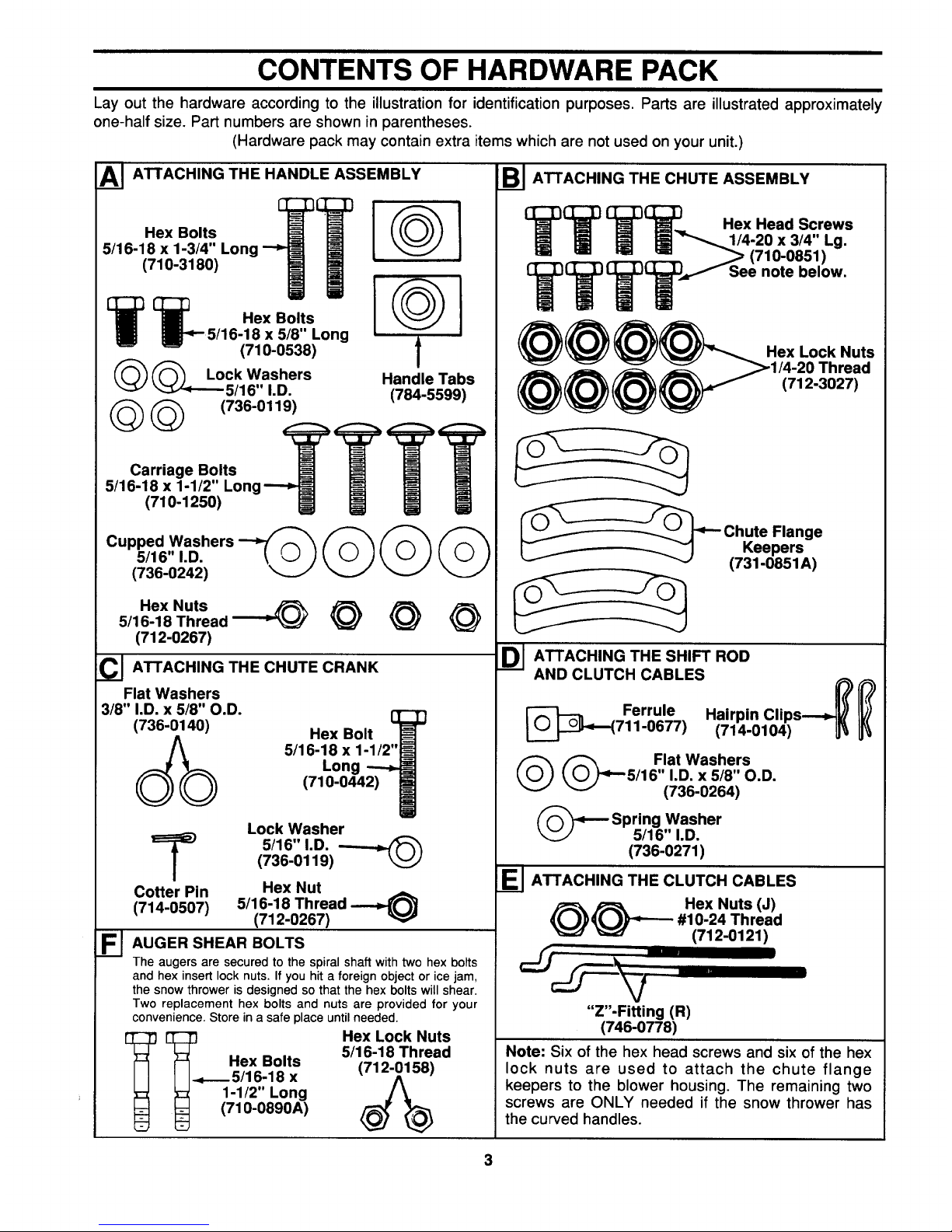
CONTENTS OF HARDWARE PACK
Lay out the hardware according to the illustration for identification purposes. Parts are illustrated approximately
one-half size. Part numbers are shown in parentheses.
(Hardware pack may contain extra items which are not used on your unit.)
AI ATTACHING THE HANDLE ASSEMBLY
Hex Bolts
5/16-18 x 1-3/4" Long
(710-3180)
@
1_{_ Hex Bolts
5/16-18 x 5/8" Long
(710-0538) t
(_(_ Lock Washers Handle Tabs
"--_!,J"_'-- 5/16" 1.D. (784-5599)
(_(_ (736-0119)
Carriage Bolts _TTT
5/16-18 x 1-1/2" Long
(710-1250)
Cupped Washers
5/16" I.D.
(736-0242)
©©
Hex Nuts
5/16-18 Thread _"_ _
(712-0267)
CI ATTACHING THE CHUTE CRANK
Flat Washers
3/8" I.D. x 5/8" O.D.
(736-0140)
&
Hex Bolt
5/16-18 x 1-1/2"
Long
(710-0442)
Lock Washer
T 5/16",.o.
(736-0119)
Cotter Pin Hex Nut
5/16-18 Thread
(714-0507)
(712-0267)
FI AUGER SHEAR BOLTS
The augers are secured to the spiral shaft with two hex bolts
and hex insert lock nuts. If you hit a foreign object or ice jam,
the snow thrower is designed so that the hex bolts will shear.
Two replacement hex bolts and nuts are provided for your
convenience. Store in a safe place until needed.
Hex Lock N(_ts
[3_ 5/16-18 Thread
Hex Bolts
I I-._.--5/16-18 x
1-1/2" Long
_ (710-0890A)
Sl ATTACHING THE CHUTE ASSEMBLY
(_ _C]_[} Hex Head Screws
[_] I_"_"-..,,, 1/4-20 x 3/4" Lg.
_,.,.__,.,_ _ (710-0851)
TT,_,/'f See note below.
@@ Hex Lock Nuts
(712-3027)
Chute Flange
Keepers
(731-0851 A)
DI ATTACHING THE SHIFT ROD
AND CLUTCH CABLES
[_}_i_( Ferrule Hairpin Clips-_) __)
711-0677) (714-0104) IJ_
_(_ Flat Washers
5/16" I.D. x 5/8" O.D.
(736-0264)
Spring Washer
5/16" I.D.
(736-0271)
_ ATTACHING THE CLUTCH CABLES
_)_ Hex Nuts (J)
#10-24 Thread
(712-0121)
"Z"-FitUng (R)
(746-0778)
Note: Six of the hex head screws and six of the hex
lock nuts are used to attach the chute flange
keepers to the blower housing. The remaining two
screws are ONLY needed if the snow thrower has
the curved handles.
3
Page 4
I I
ASSEMi3LY INSTRUCTIONS
IMPORTANT: This unit is shipped WITHOUT
GASOLINE or OIL. After assembly, see separate
engine manual for proper fuel and engine oil rec-
ommendations.
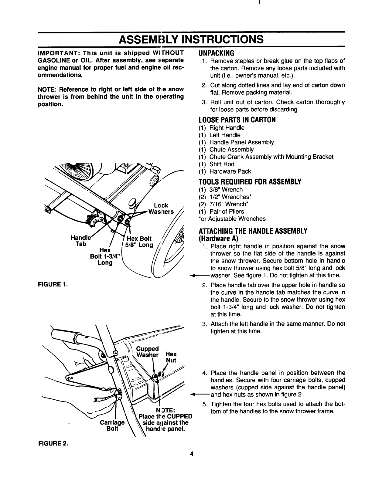
NOTE: Reference to right or left side of tl_e snow
thrower is from behind the unit in the ol)erating
position.
Hex Bolt
Tab 5/8" Long
Hex
Bolt 1-3/4"
Long
L©ck
/
FIGURE 1.
UNPACKING
1. Remove staples or break glue on the top flaps of
the carton. Remove any loose parts included with
unit (i.e., owner's manual, etc.).
2. Cut along dotted lines and lay end of carton down
flat. Remove packing material.
3. Roll unit out of carton. Check carton thoroughly
for loose parts before discarding.
LOOSEPARTSIN CARTON
(1) Right Handle
(1) Left Handle
(1) Handle Panel Assembly
(1) Chute Assembly
(1) Chute Crank Assembly with Mounting Bracket
(1) Shift Rod
(1) Hardware Pack
TOOLS REQUIRED FOR ASSEMBLY
(1) 3/8" Wrench
(2) 1/2" Wrenches*
(2) 7/16" Wrench*
(1) Pair of Pliers
*or Adjustable Wrenches
ATTACHINGTHE HANDLEASSEMBLY
(HardwareA)
1. Place right handle in position against the snow
thrower so the flat side of the handle is against
the snow thrower. Secure bottom hole in handle
to snow thrower using hex bolt 5/8" long and lock
-<--_washer. See figure 1. Do not tighten at this time.
2. Place handle tab over the upper hole in handle so
the curve in the handle tab matches the curve in
the handle. Secure to the snow thrower using hex
bolt 1-3/4" long and lock washer. Do not tighten
at this time.
.
Attach the left handle in the same manner. Do not
tighten at this time.
FIGURE 2.
Carriage
Bolt
Cupped
Washer Hex
Nut
N _TE:
Place tPe CUPPED
side a!|ainst the
hand lepanel.
4. Place the handle panel in position between the
handles. Secure with four carriage bolts, cupped
washers (cupped side against the handle panel)
-<_and hex nuts as shown in figure 2.
5. Tighten the four hex bolts used to attach the bot-
tom of the handles to the snow thrower frame.
4
Page 5
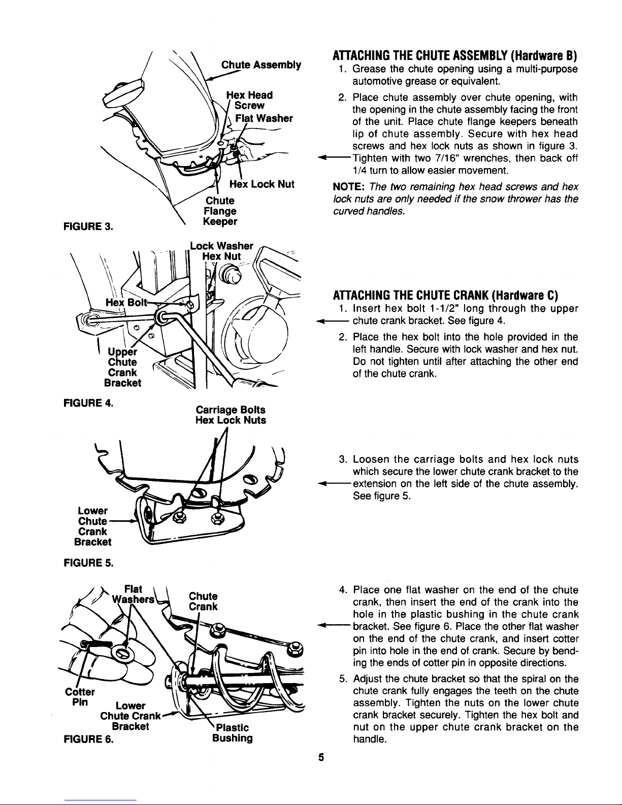
FIGURE3.
ChuteAssembly
HexHead
Screw
FlatWasher
HexLockNut
Chute
Flange
Keeper
Lock Washer
Hex Nut
ATTACHINGTHECHUTEASSEMBLY(HardwareB)
1. Grease the chute opening using a multi-purpose
automotive grease or equivalent.
2. Place chute assembly over chute opening, with
the opening in the chute assembly facing the front
of the unit. Place chute flange keepers beneath
lip of chute assembly. Secure with hex head
screws and hex lock nuts as shown in figure 3.
-<_Tighten with two 7/16" wrenches, then back off
1/4 turn to allow easier movement.
NOTE: The two remaining hex head screws and hex
lock nuts are only needed if the snow thrower has the
curved handles.
Hex
Upl
Chute
Crank
Bracket
FIGURE 4.
Carriage Bolts
Hex Lock Nuts
ATTACHINGTHECHUTECRANK(HardwareC)
1. Insert hex bolt 1-1/2" long through the upper
-<_ chute crank bracket. See figure 4.
2. Place the hex bolt into the hole provided in the
left handle. Secure with lock washer and hex nut.
Do not tighten until after attaching the other end
of the chute crank.
Lower
Crank
Bracket
FIGURE 5.
3. Loosen the carriage bolts and hex lock nuts
which secure the lower chute crank bracket to the
extension on the left side of the chute assembly.
See figure 5.
Flat
Cotter
Pin Lower
Chute Cra
Bracket
FIGURE 6.
Chute
Crank
'Plastic
Bushing
4. Place one flat washer on the end of the chute
crank, then insert the end of the crank into the
hole in the plastic bushing in the chute crank
-<----- bracket. See figure 6. Place the other flat washer
on the end of the chute crank, and insert cotter
pin into hole in the end of crank. Secure by bend-
ing the ends of cotter pin in opposite directions.
5. Adjust the chute bracket so that the spiral on the
chute crank fully engages the teeth on the chute
assembly. Tighten the nuts on the lower chute
crank bracket securely. Tighten the hex bolt and
nut on the upper chute crank bracket on the
handle.
5
Page 6

E I
IMPORTANT: Attach the shift rod and chltch cables as follows. THEN CHECK THE ADJUSTMENTS AS
INSTRUCTED, AND MAKE ANY FINAL ADJUSTMENTS NECESSARY BEFORE OPERATING YOUR
SNOW THROWER. Failure to follow the ivtstructions may cause damage to the snow thrower.
Hairp,n
Clip !
FIGURE 7.
Traction
Shift
Lever
Spring
Washer
it Washer
om
Hole
ATTACHINGTHE SHIFT ROD (Hardware D)
1. Insert the ferrule through the lower hole in the
shift lever (beneath the handle panel) from the left
side. Secure with flat washer and hairpin clip. See
figure 7.
Place the shift lever in the sixth (6) speed position
(all the way forward).
3. Start threading the shift rod into the ferrule. Push
down on the shift arm assembly as far as it will
go. Thread shift rod into the ferrule until the end
of the shift rod lines up with the hole in the shift
arm assembly. Secure with spring washer, flat
washer and hairpin clip.
Make certain to check for correct adjustment of the
shift rod as instructed in the Final Adjustment section
before operating the snow thrower.
ATTACHINGTHE CLUTCH CABLES
The "Z" end of the clutch cables are hooked into the
clutch grips on each handle. Attach cables as follows.
1. Thread the hex lock nuts (in hardware pack) all
the way up the threaded portion of the "Z" ends
of the clutch cables.
2. Make certain each cable is in groove of cable
roller guides. Place the clutch grip in the raised
(up) position.
3. Thread the cable onto the threaded portion of the
"Z" end until there is no slack in the cable, but the
cable is NOT tight. Do not overtighten cable.
See figure 8.
&
WARNING: If cable is tightened so there
is tension on the cable with the clutch
grip released, the safety features of the
snow thrower may be overridden.
4. When correct adjustment is reached, tighten the
hex nut against the bottom portion of the cable to
lock it in position.
FIGURE 8.
is Straight
/
6
FINAL ADJUSTMENTS
Auger Drive Clutch
To check the adjustment of the auger drive clutch,
push forward on the left hand clutch grip (depress the
rubber bumper). There should be slack in the cable.
Release the clutch grip. The cable should be straight.
Make certain you can depress the auger drive clutch
grip against the left handle completely.
Page 7

Ifnecessary,loosenthehexlocknutandthreadthe
cablein(forlessslack)orout(formoreslack)asnec-
essary.Referto figure8. Rechecktheadjustment.
Tightenthe locknut againstthe cablewhencorrect
adjustmentisreached.
Traction Drive Clutch and Shift Lever Adjustment
To check the adjustment of the traction drive clutch
and shift lever, tip the snow thrower forward so that it
rests on the auger housing. First move the shift lever
all the way forward to sixth (6) position. With the trac-
tion drive lever released, spin the snow thrower
wheels by hand. They should turn freely. Then
engage the traction drive clutch grip. The wheels
should stop turning.
Now release the traction drive clutch grip, and spin
the wheels again. Move the shift lever back to the fast
reverse position, then all the way forward again.
There should be no resistance in the shift lever, and
the wheels should keep turning.
If you have resistance when moving the shift lever or
the wheels stop when they should not, loosen the lock
nut on the traction drive cable and unthread the cable
one turn. If the wheels do not stop when you engage
the traction drive clutch grip, loosen the lock nut on
the traction drive cable and thread the cable in one
turn. Recheck the adjustment and repeat adjustment
as necessary. Tighten the lock nut to secure the cable
when correct adjustment is reached.
NOTE: If you are uncertain that you have reached the
correct adjustment, refer to the Adjustment section on
page 10.
ADJUSTING THE SKID SHOES
The space between the shave plate and the ground
can be adjusted. For close snow removal, place skid
shoes in the low position. Use middle or high position
when area to be cleared is uneven. See figure 9.
Adjust skid shoes by loosening the four hex nuts and
carriage bolts and moving skid shoes to desired posi-
tion. Make certain the entire bottom surface of skid
shoe is against the ground to avoid uneven wear on
the skid shoes. Retighten nuts and bolts securely.
It is not recommended that you operate this snow
thrower on gravel as loose gravel can be easily
picked up and thrown by the auger causing an injury
or damage to the snow thrower.
Skid
Shoe
FIGURE 9.
Hex Nuts
Carriage Bolts
OPTIONAL ELECTRICSTARTER
If your unit is equipped with an optional electric starter
which has not been installed at the factory, install at
this time. Follow the instructions packed with the elec-
tric starter for installation.
TIRE PRESSURE (Pneumatic Tires)
The tires are over-inflated for shipping purposes.
Check tire pressure and reduce to 15 to 20 psi.
NOTE: If the tire pressure is not equal in both tires,
the unit may pull to one side or the other.
Auger
Drive
Clutch
CONTROLS
Traction
Drive/
Auger
Clutch
Lock
SHIFT LEVER
(See figures 10 and 11)
The shift lever is located in the center
of the handle panel. The shift lever may
be moved into one of eight positions.
Run engine with throttle in the fast posi-
tion. Use the shift lever to determine
ground speed.
Forwardmone of six speeds. Position
number one (1) is the slowest. Position
number six (6) is the fastest.
FIGURE 10.
7
Reverse--two reverse (R) speeds. "R"
closest to the operator (all the way
back) is the faster of the two.
FIGURE 11.
Page 8

I I
AUGER DRIVE (See figure 10)
The auger drive clutch is located on the lef handle.
Squeeze the clutch grip to engage the augers.
Release to stop the snow throwing action. Traction
drive clutch must also be released.)
TRACTION DRIVE/AUGER CLUTCH LOCK
(See figure 10)
The traction drive clutch is located on the righc handle.
Squeeze the traction drive clutch to engage tile wheel
drive. Release to stop.
This same lever also locks the auger clutct_ so you
can turn the chute crank without interrupting 1he snow
throwing process. If the auger drive clutch is .=ngaged
with the traction drive clutch engaged, the _perator
can release the auger drive clutch (on the lef handle)
and the augers will remain engaged. Release the
traction drive clutch to stop both the augers atld wheel
drive (auger drive clutch must also be release J).
CHUTECRANK (See figure 10)
The chute crank is located on left hand sic e of the
snow thrower.
To change the direction in which snow is thrc,wn, turn
chute crank as follows:
1. Crank clockwise to discharge to the left.
2. Crank counterclockwise to discharge to ttne right.
THROTTLE CONTROL(See figure 12)
The throttle control is located on the engine. It regu-
lates the speed of the engine.
SAFETYIGNITION SWITCH (See figure 12)
The ignition key must be inserted in the switch before
the unit will start. Remove the ignition key when snow
thrower is not in use.
Choke
Primer
Rope
Ignit Starter
Key Throttle Handle
Control
FIGURE 12.--Model 610E Shown
13PERATION
GASAND OIL FILL-UP
Service the engine with gasoline anq! oil as
instructed in the separate engine manual packed with
your snow thrower. Read instructions carefi dly.
NOTE: Your snow thrower is shipped without oil;how-
ever, a small amount of oil may be present from the
factory. Do not overfill.
,_ WARNING: Never fill fuel tank indoors,
with engine running or while eulgine is
hot. Do not smoke when filling fu=:ltank.
ELECTRICSTARTER
WARNING: The optional electric starter is €_quipped
with a three-wire power cord and plug and is
designed to operate on 120 volt AC housel_old cur-
rent. It must be properly grounded at all times to avoid
the possibilityof electric shock which may be injurious
to the operator. Follow all instructions carefully.
Determine that your house wiring is a th'ee-wire
grounded system. Ask a licensed electrician i: you are
not certain. Ifyour house wiring system is no1 a three-
wire grounded system, do not use this electr c starter
under any conditions. If your system is grour ded and
a three-hole receptacle is not available at 1he point
your starter will normally be used, one should be
installed by a licensed electrician.
When connecting the power cord, always connect
cord to starter on engine first, then plug the other end
into a three-hole grounded receptacle.
When disconnecting the power cord, always unplug
the end from the three-hole grounded receptacle first.
TO START ENGINE
IMPORTANT: If unit shows any sign of motion (drive
or augers) with the clutch grips disengaged, shut
engine off immediately. Readjust as instructed in the
"Final Adjustments" section of the Assembly
Instructions.
1. Attach spark plug wire to spark plug.
2. Make certain the auger drive and traction
drive clutch grips are in the disengaged
(released) position.
3. Move throttle control up to FAST position. Insert
ignition key into slot. See figure 12. Be certain it
snaps into place. Do not turn key.
4. Rotate choke knob to FULL choke position (cold
engine start).
If engine is warm, place choke in OFF position
instead of FULL.
8
Page 9

5. Electric Start Only (Optional): Connect power
cord to switch box on engine. Plug the other end
of power cord into a three-hole, grounded 120
volt AC receptacle.
6. Push primer button t_vo or three times. See figure
12.
If engine is warm, push primer button once only.
NOTE: Always cover vent hole in primer button when
pushing. Additional priming may be necessary for first
start if temperature is below 15°F.
7. Recoil Start: Grasp starter handle (see figure 12)
and pull rope out slowly, until it pulls slightly hard-
er. Let rope rewind slowly. Pull starter handle
rapidly. Do not allow handle to snap back. Allow it
to rewind slowly while keeping a firm hold on the
starter handle.
.
9.
Electric Start (Optional): Push starter button on
top of the engine to crank the engine. When
engine starts, release starter button.
Repeat step 7 until engine starts. If engine fails to
start, repeat steps 6 and 7 until engine starts.
As engine warms up and begins to operate even-
ly, rotate choke knob slowly to OFF position. If
engine falters, return to FULL choke, then slowly
move to OFF position.
Recoil Starter: With engine running, pull starter rope
with a rapid, continuous full arm stroke three or four
times. Pulling the starter rope will produce a loud clat-
tering sound, which is not harmful to the engine or
starter.
3. To stop engine, remove the ignition key. Do not
turn key. Disconnect the spark plug wire from the
spark plug to prevent accidental starting while
equipment is unattended.
NOTE: Do not lose ignition key. Keep it in a safe
place. Engine will not start without the ignition key.
4. Wipe all snow and moisture from the carburetor
cover in the area of the control levers. Also, move
control levers back and forth several times. Leave
throttle control lever in the STOP or OFF position.
Leave choke control in the FULL choke position.
AVOIDINJURYFROM ROTATING
AUGERm KEEPHANDS,FEET
ANDCLOTHINGAWAY. ,_,
TO STOP ENGINE
1. Run engine for a few minutes before stopping to
help dry off any moisture on the engine.
2. To help prevent possible freeze-up of starter, pro-
ceed as follows.
Optional Electric Starter: Connect power cord to
switch box on engine, then to 120 volt AC receptacle.
With the engine running, push starter button and spin
the starter for several seconds. The unusual sound
made by spinning the starter will not harm engine or
starter. Disconnect the power cord from receptacle
first, and then from switch box.
TO ENGAGEDRIVE
1. With the engine running near top speed, move
shift lever into one of the six FORWARD positions
or two REVERSE positions. Select a speed
appropriate for the snow conditions that exist.
Use the slower speeds until you are familiar with
the operation of the snow thrower.
2. Squeeze the traction drive clutch grip against the
right handle and the snow thrower will move.
Release it and the drive motion will stop.
NOTE: NEVER move shift lever without first releasing
the drive clutch.
TIRE CHAINS (Optional Equipment)
Tire chains should be used whenever extra traction is
needed.
OPERATINGTIPS
NOTE: Allow the engine to warm up for a few minutes
as the engine will not develop full power until it reach-
es operating temperature.
&
WARNING: Temperature of muffler and
surrounding areas may exceed 150°F.
Avoid these areas.
Page 10

t I
1. For most efficient snow removal, remo_e snow
immediately after it falls.
2. Discharge snow downwind whenever Ic,ossible.
Slightly overlap each previous swath.
3. Set the skid shoes 1/4" below the scrap_ r bar for
normal usage. The skid shoes may be _djusted
upward for hard-packed snow. Adjust d(_wnward
when using on gravel or crushed rock.
4. Be certain to follow the precautions list_ d under
"To Stop Engine" on page 9 to prevent possible
freeze-up.
5. Clean the snow thrower thoroughly after each
use.
ADJUSTMENTS
WARNING: NEVER attempt t(, clean
chute or make any adjustments while
engine is running.
CHUTEASSEMBLYADJUSTMENT
The distance snow is thrown can be adjL,sted by
adjusting the angle of the chute assembly. Th_ sharp-
er the angle, the shorter the distance snow is thrown.
See figure 13.
To adjust chute assembly, loosen the hard knob.
Pivot the top of the chute assembly to )osition
desired. Retighten the hand knob.
TRACTIONDRIVECLUTCHADJUSTMENT
Refer to the Final Adjustment section of the Assembly
Instructions to adjust the traction drive clutch. If you
are uncertain that you have reached the correct
adjustment, the adjustment can be physically checked
as follows.
With the snow thrower tipped forward (be certain to
drain the gasoline or place plastic film under the gas
cap if the snow thrower has already been operated),
remove the frame cover underneath the snow thrower
by removing six self-tapping screws.
With the traction drive clutch released, there must be
clearance between the friction wheel and the drive
plate in all positions of the shift lever. With the traction
drive clutched engaged, the friction wheel must con-
tact the drive plate. See figure 14.
If adjustment is necessary, loosen the lock nut on the
traction drive cable and thread the cable in or out as
necessary. Tighten the lock nut to secure the cable
when correct adjustment is reached. Reassemble the
frame cover.
NOTE: If you placed plastic under the gas cap, be
certain to remove it.
Friction
Wheel
Gear Shaft
!
Drive
Pl_
FIGURE 14.
FIGURE 13.
SKID SHOE ADJUSTMENT
The space between the shave plate and th_ ground
can be adjusted. Refer to page 7 of the A ;sembly
Instructions.
AUGERCLUTCH ADJUSTMENT
To adjust the auger clutch, refer to Final Adjustment
section of Assembly Instructions.
10
SHIFT ROD ADJUSTMENT
To adjust the shift rod, remove the hairpin clip and flat
washer which secure the shift rod to the shift arm
assembly. Refer to figure 7. Adjust as specified in
Assembly Instructions.
Page 11

CARBURETORADJUSTMENT
&
WARNING: If any adjustments are made
to the engine while the engine is running
(e.g. carburetor), keep clear of all moving
parts. Be careful of heated surfaces and
muffler.
Minor carburetor adjustment may be required to com-
pensate for differences in fuel, temperature, altitude
and load.
Refer to the separate engine manual packed with
your unit for carburetor adjustment information.
DRIVE WHEELS
The wheels may be adjusted for two different meth-
ods of operation. The adjustment is made by placing
the klick pins in one of two different holes on the right
side of the unit. See figure 15.
1. One Wheel DrivingmPlace klick pin in the out-
side axle hole on the right side. This position
gives power drive to the left wheel only, making
the unit easier to maneuver.
,
Both Wheels Driving--Place klick pin in the hole
in the hub next to the rim on the right side. This
position is good for heavy snow as there is power
drive in both wheels.
IMPORTANT: Keep all grease and oil off of the
friction wheel and drive plate.
Shifting Mechanism
Lubricate the shifting mechanism and pivot points on
the shift rod with engine oil at least once a season or
after every 25 hours of operation,
Traction Drive/Auger Clutch Lock
The cams on the ends of the control rods which inter-
lock the traction drive and auger drive clutches must
be lubricated at least once a season or every twenty-
five hours of operation. The cams can be accessed
beneath the handle panel. Refer to page 16, refer-
ence 39. Use a multi-purpose automotive grease.
Gear Case
The gear case is lubricated with grease at the factory
and does not require checking. If disassembled for
any reason, lubricate with 2 ounces of Shell Alvania
grease, part number 737-0168.
Bearings
Lubricate the auger and wheel bearings once a sea-
son with lightoil.
AUGERS
The augers are secured to the spiral shaft with two
hex bolts and hex lock nuts. See figure 16. If you hit a
foreign object or ice jam, the snow thrower is
designed so that the hex bolts will shear.
If the augers will not turn, check to see if the hex bolts
have sheared. Two replacement hex bolts and hex
lock nuts have been provided with the snow thrower.
For future use, order part number 710-0890 (hex bolt
5/16-18 x 1.5" long) and 712-0429 (hex insert lock nut
5/16-18 thread).
Outside Hole
in Axle
FIGURE 15.
MAINTENANCE
WARNING: Disconnect the spark plug
wire and ground against the engine
before performing any repairs or mainte-
nance.
LUBRICATION
Gear Shaft
Lubricate the gear shaft with "Slick 50 Grease" at
least once a season or after every 25 hours of opera-
tion (available at automotive stores, or order part
number 737-0290). Refer to figure 14.
Au Bolts
FIGURE 16.
11
SHAVE PLATEAND SKID SHOES
The shave plate and skid shoes on the bottom of the
snow thrower are subject to wear. They should be
checked periodically and replaced when necessary.
Page 12

[ I
To remove skid shoes, remove the four carri_ ge bolts,
belleville washers and hex nuts which attacl" them to
the snow thrower. Reassemble new skid sl'oes with
the four carriage bolts, belleville washers (cupped
side goes against skid shoes) and hex nu s. Make
certain the skid shoes are adjusted to be leveI.
To remove shave plate, remove the carria;le bolts,
belleville washers and hex nuts which attact" it to the
snow thrower housing. Reassemble new sh_ve plate,
making sure heads of the carriage bolts a'e to the
inside of the housing. Tighten securely.
ENGINE
Refer to separate engine manual for al engine
maintenance procedures.
BELTREMOVALAND REPLACEMENT
WARNING: Disconnect the sp_rk plug
wire from the spark plug and grm,nd.
AUGER BELTS
NOTE: It is necessary to remove both belts h_order to
change either one. If changing just one beh, be cer-
tain to check the condition of the other be 't (model
610E has only one auger belt).
1. Remove the plastic belt cover on the fr(nt of the
engine by removing the two self-tappin( screws.
See figure 17.
5. Roll the front and rear auger belts off the engine
pulley. See figure 18.
Drive
Belt
Rear
Auger Engine
Front
er
Belt
Engine
Pulley
Idler Idler
Pulley Pulley
FIGURE 18.
6. Unhook the idler spring from the hex bolt on the
auger housing. See figure 19.
7. Unhook the support bracket spring from the
frame.
8.
.
Lift the front auger belt from the auger pulley, and
slip belt between the support bracket and the
auger pulley. See figure 19. Repeat this step for
rear auger belt (except model 610E).
Replace both auger drive belts by following
instructions in reverse order.
Belt Lpping
Cover €;crews
FIGURE 17.
2. Drain the gasoline from the snow thrower, or
place a piece of plastic under the gas cal).
3. Tip the snow thrower up and forward _;o that it
rests on the housing.
4. Remove six self-tapping screws from tile frame
cover underneath the snow thrower.
12
DRIVE BELT
1. Follow steps 1 through 4 of previous instructions.
2. Pull idler pulley up, and lift belt off engine pulley
and friction wheel disc. See figure 18.
3. Using a 7/16" wrench, loosen the nut on the stop
bolt until the support bracket rests on the auger
pulley. See figure 20.
4. Slip belt between friction wheel and friction wheel
disc. See figure 20. Remove and replace belt.
Reassemble following the instructions in reverse
order.
NOTE: The support bracket must rest on the stop bolt
after the new belt has been assembled. See figure 20.
Page 13

Friction
Wheel
Auger
Pulley Auger
Pulley
Idler Auger Support
Spring Housing Bracket
SpringFIGURE 19.
Bolt
Drive
Belt
,
Remove the klick pins which secure the wheels,
and remove the wheels from the axle,
5. Remove the gear shaft from the unit by removing
the bolts, lock washers and flat washers from
each side of the frame. See figure 21. Hold the
friction wheel assembly, and slide the gear shaft
out of the unit toward the right hand side. Refer to
figure 14.
6. Remove the six screws from the friction wheel
assembly (three from each side). Remove the
friction wheel rubber from between the friction
wheel plate.
7. Reassemble new friction wheel rubber to the fric-
tion wheel assembly, tightening the six screws in
rotation and with equal force.
8. Slide the friction wheel assembly up onto the shift
mechanism as shown in figure 14, and slide the
gear shaft back into the unit. Reassemble in
reverse order.
FIGURE 21.
Auger
FIGURE 20. Pulley
CHANGING THEFRICTION WHEEL RUBBER
The rubber on the friction wheel is subject to wear
and should be checked after 25 hours of operation,
and periodically thereafter. Replace the friction wheel
rubber if any signs of wear or cracking are found.
1. Drain the gasoline from the snow thrower, or
place a piece of plastic under the gas cap.
2. Tip the snow thrower up and forward, so that it
rests on the housing.
3. Remove six self-tapping screws from the frame
cover underneath the snow thrower.
OFF-SEASON STORAGE
13
WARNING: Never store engine with fuel
in tank indoors or in poorly ventilated
areas, where fuel fumes may reach an
open flame, spark or pilot light as on a
furnace, water heater, clothes dryer or
other gas appliance.
If unit is to be stored over 30 days, prepare for stor-
age as follows:
1. Remove all gasoline from carburetor and fuel
tank to prevent gum deposits from forming on
these parts and causing possible malfunction of
engine.
Page 14

I I
a. Run engine until fuel tank is empty anq| engine
stops due to lack of fuel.
b. Drain carburetor by pressing upward on bowl
drain, located below the carburetor cov,=r.
,_ WARNING: Drain fuel into approved con-
tainer outdoors, away from opelJ flame.
Be certain engine is cool. Do not .,;moke.
Fuel left in engine during warm Neather
deteriorates and will cause serioL_s start-
ing problems.
NOTE: Fuel stabilizer (such as STA-BIL) is ar accept-
able alternative in minimizing the formatioJ1 of fuel
gum deposits during storage. Add stabilizer to gaso-
line in fuel tank or storage container. Alwaj's follow
mix ratio found on stabilizer container. Run _ngine at
least 10 minutes after adding stabilizer to a,!ow it to
reach carburetor. Do not drain carburetor if u ring fuel
stabilizer.
2. Remove spark plug and pour one (1) ounce of
engine oil through spark plug hole into cylinder.
Crank engine several times to distribute oil.
Replace spark plug.
3. Remove all dirt from exterior of engine and equip-
ment.
4. Follow lubrication recommendations on page 11.
NOTE: When storing any type of power equipment in
an unventilated or metal storage shed, care should be
taken to rust proof the equipment. Using a light oil or
silicone, coat the equipment, especially any chains,
springs, bearings and cables.
14
Page 15

TROUBLE SHOOTING GUIDE
Possible Cause(s) Corrective Action
Trouble
Engine fails to start
Engine runs erratic
Loss of power
Engine overheats
Excessive vibration
Hard to shift, or will
not shift
Unit fails to propel itself
Unit fails to discharge
snow
1. Fuel tank empty, or stale fuel.
2. Blocked fuel line.
3. Key not in switch on engine.
4. Spark plug wire disconnected.
5. Faulty spark plug.
1. Unit running on CHOKE.
2. Blocked fuel line or stale fuel.
3. Water or dirt in fuel system.
4. Carburetor out of adjustment.
1. Spark plug wire loose.
2. Gas cap vent hole plugged.
1. Engine oil level low.
2. Carburetor not adjusted properly.
Loose parts or damaged impeller.
Shift rod misadjusted.
1. Incorrect adjustment of drive clutch.
2. Drive belt loose or damaged.
1. Auger shear bolt broken.
2. Discharge chute clogged.
3. Foreign object lodged in auger.
4. Incorrect adjustment of auger drive
clutch.
5. Auger drive belt loose or damaged.
1. Fill tank with clean, fresh gasoline.
2. Clean fuel line.
3. Insert key.
4. Connect wire to spark plug.
5. Clean, adjust gap or replace.
1. Turn choke knob to OFF position.
2. Clean fuel line; fill tank with clean
fresh gasoline.
3. Use carburetor bowl drain to drain
fuel tank. Refill with fresh fuel.
4. Adjust carburetor. See separate
engine manual.
1. Connect and tighten spark plug
wire.
2. Remove ice and snow from cap.
Be certain vent hole is clear.
1. Fill crankcase with proper oil.
2. Adjust carburetor. See separate
engine manual.
Stop engine immediately and
disconnect spark plug wire. Tighten
all bolts and nuts. Make all
necessary repairs. If vibration
continues, have unit serviced by
authorized service dealer.
Readjust shift rod. See Adjustment
section of this manual.
1. Adjust drive clutch. Refer to
Adjustment section.
2. Replace drive belt. Refer to
Maintenance section.
1. Replace auger shear bolt. Refer to
Maintenance section.
2. Stop engine immediately and
disconnect spark plug wire. Clean
discharge chute and inside of auger
housing.
3. Stop engine immediately and
disconnect spark plug wire.
Remove object from auger.
4. Adjust auger clutch. Refer to
Adjustment section.
5. Replace auger drive belt. Refer to
Maintenance section.
NOTE: For repairs beyond the minor adjustments listed above, please contact your nearest authorized service dealer.
15
Page 16

E I
Copy lh¢ information from
your model plate here:
NNN NNSN NNN
NNNNNNNN
1-11ZII-Ii-II-II-II-II-II-II-1FI
modelnumber
available
whenyoucall
Model Series
Shave Plate
Skid Shoe
Auger Belts
Drive Belt
Friction Wheel Rubber
Friction Wheel Ass'y. Comp.
SAE 5W30
Electric Start Kit
Tire Chains
ht Kit
Drift Cutter Kit
Snow Cab
Illustrated Parts List*
E610E
, '25-1660
7 34-5581A
84-5580
54-0430
E640F
725-1660
784-5579
784-5580
754-0430(2 _q'd.)
_'54-0343
;'35-0243
634-0042A
J-8C
730226
:;tandard
3c0-139-000
N/A
3_c0-679-000
3cO-674-000
770-96-9B
754-0346
735-0243
684-0042A
J-8C
730226
Standa_
390-991-000
390-255-000
390-679-000
390-674-000
770-96-9B
E660G
725-1660
784-5582A
784-5580
754-0430(2
754-0346
735-0243
684-0042A
J-8C
730226
Standard
390-655-000
390-255-000
390-679-000
390-674-000
770-96-9B
*Either use the order form attached to this manual or telephone 1 (800) 800-7310.
Wait for the message and then press _2) for literature. An operator will take your order.
For Parts, Acces;sorles or Service Information,
CALL NOW!
1f8oo) 8oo-y31o
8:00 AM to 8:00 PM Monday Through Saturday
12 Noo n to 6:00 PM Sunday
Eastern Tim • (winter hours may vary)
The only way to ensure the pe=/ormance of your product
is to use original equipmen: parts and accessories.
MTD designs and engineers quality parts to exacting
specifications. When you sub stitute, you take a chance
on quality, reliability, safety al=d performance. Use MTD
original equipment, the be.,;t buy on the American
Landscape---American Made _nd American Owned!
 Loading...